UT Design (14.11.05)
31
DESIGN OF DECK SLAB FOR BRIDGE Design of RCC Deck Slab for 5.0m clear span : Clear Span = 5.00 m Assumed thickness of slab = 400 mm Clear cover = 35 mm Main reinforcement = 16mm Φ HYSD bars Effective depth available = 400 - 35 - 16/2 = 357 mm The single lane road bridge is designed for IRC class 'A' loading. The RCC Deck Slab is proposed in M - 20 grade. Allowable stresses : [ RCC M-20] σcbc = 7 N/mm 2 σst = 190 N/mm 2 m = 13.33 k = 0.3872 j = 0.8709 Q = 1.1802 Unit weight of water = 10 KN/m3 Unit weight of concrete = 25 KN/m 3 Effective span will be least of the following : i) C/C of Support = 5.0 + 0.5 [bearing] = 5.5 m ii) Clear Span +Effective depth = 5.00 + 0.357 = 5.357 m Therefore Effective span = 5.357 m Clear Carriage way width = 4.25 m Width of slab = 4.25 + 2 x 0.225 + 2 x0.2 - 2 x 0.09 = 4.92 m [As per Clause 211.2 of IRC 6 - Pg.22] Impactor factor = 4.5/(6.0+Effective span) = 0.396 m Bending Moment due to Dead Load : Weight of Slab & Wearing Coat = (0.4 + 0.075) x 25 = 11.875 kN Bending Moment [Wl 2 /8] = 11.875 x 5.357^2/8 = 42.60 kN - m Bending Moment due to Live Load : [As per IRC code 21 -2000, section 305.16.2] B ef = α x a x (1-(a/L o)) + b w Where B ef = the eff ective wi dt h of slab on wh ich the road act s. L o = the effective span. A = b w = α = where b is the width of the sl ab. [b/L o ] = [4.92/5.357] = 0.918 For [b/L o ] of For [α] value 0.900 2.360 1.000 2.480 Difference 0.100 Difference 0.120 α = 2.36+[0.018x0.12]/0.10 = 2.382 the dist an ce of the cent re of gra vi ty of th e concent ra te d load fr om the nearest support. the br eadth of concentr ation ar ea of the load i.e the di mension of the type/ track contact areaover the road surface of the slab in a direction at right angles to the spanplus twice the thickness of wearing coat or surface finish above the structural slab and A constant having the following values depending upon the ration b/L o Road Bridge Design Page1
-
Upload
p-allen-samuel-ignatius -
Category
Documents
-
view
214 -
download
0
Transcript of UT Design (14.11.05)

8/11/2019 UT Design (14.11.05)
http://slidepdf.com/reader/full/ut-design-141105 1/31
DESIGN OF DECK SLAB FOR BRIDGE
Design of RCC Deck Slab for 5.0m clear span :
Clear Span = 5.00 m
Assumed thickness of slab = 400 mm
Clear cover = 35 mm
Main reinforcement = 16mm Φ HYSD barsEffective depth available = 400 - 35 - 16/2
= 357 mm
The single lane road bridge is designed for IRC class 'A' loading.
The RCC Deck Slab is proposed in M - 20 grade.
Allowable stresses : [ RCC M-20]
σcbc = 7 N/mm2
σst = 190 N/mm2
m = 13.33
k = 0.3872
j = 0.8709
Q = 1.1802
Unit weight of water = 10 KN/m3
Unit weight of concrete = 25 KN/m3
Effective span will be least of the following :
i) C/C of Support = 5.0 + 0.5 [bearing]= 5.5 m
ii) Clear Span +Effective depth = 5.00 + 0.357
= 5.357 m
Therefore Effective span = 5.357 m
Clear Carriage way width = 4.25 m
Width of slab = 4.25 + 2 x 0.225 + 2 x0.2 - 2 x 0.09
= 4.92 m
[As per Clause 211.2 of IRC 6 - Pg.22]
Impactor factor = 4.5/(6.0+Effective span)
= 0.396 m
Bending Moment due to Dead Load :
Weight of Slab & Wearing Coat = (0.4 + 0.075) x 25
= 11.875 kN
Bending Moment [Wl2
/8] = 11.875 x 5.357^2/8= 42.60 kN - m
Bending Moment due to Live Load : [As per IRC code 21 -2000, section 305.16.2]
Bef = α x a x (1-(a/Lo)) + bw
Where Bef = the effective width of slab on which the road acts.
Lo = the effective span.
A =
bw =
α =where b is the width of the slab.
[b/Lo] = [4.92/5.357]
= 0.918
For [b/Lo] of For [α] value
0.900 2.360
1.000 2.480
Difference 0.100 Difference 0.120
α = 2.36+[0.018x0.12]/0.10
= 2.382
the distance of the centre of gravity of the concentrated load from
the nearest support.
the breadth of concentration area of the load i.e the dimension of the
type/ track contact area over the road surface of the slab in a
direction at right angles to the span plus twice the thickness of
wearing coat or surface finish above the structural slab and
A constant having the following values depending upon the ration
b/Lo
Road Bridge Design Page1

8/11/2019 UT Design (14.11.05)
http://slidepdf.com/reader/full/ut-design-141105 2/31
Dispersion width under 'C' [11.40 t]
Bef = α x a x (1-(a/Lo)) + bw
= 2.382 x 2.379 x [1-2.379/5.357] +0.65
= 3.80 m
> 1.8 m
Hence dispersion width overlap.
Therefore, combined width of dispersion = 1.8 + [0.225+0.15+(0.5/2)]+3.8/2
= 4.325 m
Intensity of load = Load (impact factor)/combined dispersion width
= 3.68 t
= 36.8 kN
Dispersion width under 'D'
Bef = α x a x (1-(a/Lo)) + bw
= 2.382 x 1.778 x [1-1.778/5.357] +0.65
= 3.48 m
> 1.8 m
Hence dispersion width overlap.
Therefore, combined width of dispersion = 1.8 + 0.625+3.48/2
= 4.165 m
Intensity of load = Load (impact factor)/combined dispersion width
= 3.82 t
= 38.2 kN
For maximum bending moment the position of load system is as shown below:
3.677
2.379 0.3 0.3 0.6
A C D B
5.357
Taking moments about right support 'B'R A x 5.357 = 3.677 x 2.978 + 3.829 x 1.778
R A = 3.31 t
= 33.1 kN
Max.Bending Moment due to Live Load
= R A x 2.379
= 78.74 kN - m
Therefore totalB.M = Livel Load B.M + Dead Load B.M
= 121.34 kN - m
Effective depth required (d) = sqrt(B.M/Qb)
= sqrt((121.34x 10^6)/(1.1802 x 1000)
= 320.64 mm
Effective depth available = 320.64 mm
< 357.00 mm
Hence assumed depth of slab 400mm is O.K
Hence Safe.
1.778
2.679
3.829
For Maximum bending moment the two wheel loads of 11.40 t kept such that the resultant of two loads
and one of the loads should be kept equidistant from the centre of the span. The position of loads is
shown in the sketch.
Road Bridge Design Page2

8/11/2019 UT Design (14.11.05)
http://slidepdf.com/reader/full/ut-design-141105 3/31
Main Reinforcement Calculations:
Area of steel required (Ast) = BM/σst x j x d
= 2054.01 mm2
Therefore provide 20mm dia @
spacing = 314 x 1000/2054.01
= 152.8715 mm
Say 150 m c/c Area of steel provided = 2093.33 mm
2
Distribution steel: [ As per clause 305.18.1 of IRC code 21 - 2000, section III]
B.M considered for distribution steel.
= 0.3 x Live Load B.M + 0.2 Dead Load B.M
= 32.14 kN-m.
Area of steel [Ast] = 32.14 x 10^6/(190 x 0.8709 x 357)
= 544.10 mm2
But min. area to be provided is 0.12% of gross cross sectional area
= (0.12 x 400 x 1000)/100
= 48.00 mm2
Therefore provide 10mm dia bars @
Spacing = 78.53 x 1000/48
= 144.33 mm
say 140 mm c/c
Ast provided = 560.93 mm2
Check for shear:
Maximum shear due to dead load = WL/2
= 29.69 kN
Maximum shear due to live load, as per clause 305.16.5 of IRC 21 - 2000
Longitudinal dispersion = 0.25+2x(0.4+0.075)
= 1.2 m
Therefore the load of 11.4t may be kept at 1.2/2 = 0.6m from the support for maximum shear.
11.4 t 11.4 t
0.6
C D
A B
Dispersion under Load 'C':
Bef = α x a x (1-(a/Lo)) + bw
= 2.382 x 0.6 x [1-0.6/5.357] +0.65
= 1.92 m
> 1.8 m
Hence dispersion width overlap.
= 2.425 + 1.92/2
= 3.385 m
Intensity of Load = Load (Impact factor)/ combined dispersion width
= [11.4 x (1.396)/3.385
= 4.70 t
200
150 1800
225 250
225+150+1800+250 = 2425
1.2
5.357
Therefore, combined width of
dispersion
Road Bridge Design Page3

8/11/2019 UT Design (14.11.05)
http://slidepdf.com/reader/full/ut-design-141105 4/31
Dispersion under Load 'D':
Bef = α x a x (1-(a/Lo)) + bw
= 2.382 x [0.6+1.2] x [1-(0.6+1.2)/5.357] +0.65
= 3.50 m
> 1.8 m
Hence dispersion width overlap.
= 2.425 + 3.5/2
= 4.175 m
Intensity of Load = Load (Impact factor)/ combined dispersion width
= [11.4 x (1.396)/4.175
= 3.81 t
4.702 t 3.813 t
0.6 1.2
A B
Taking moments about 'B'
R A x 5.357 = (4.702 x 4.757) + (3.813 x 3.557)
R A = 6.71 t
= 67.07 kN
Total Shear = 67.07+29.69
= 96.76 kN
Shear stress = 96.76 x 1000/[1000 x 357]
= 0.27 N/mm2
As per clause 304.7.2 of IRC section - III, the maximum permissible shear stress
Tmax = 0.07 f ck
= 0.07 x 20
= 1.4 N/mm2
> 0.27 N/mm2
T<Tc where Tc = permissible shear stress
Tc = k1 x k2 x Tco
k1 = 1.14 - 0.7d > 0.5 [d in m]
k2 = 0.5 + 0.25p > 1Tco = basic values for different grades of concrete = 0.28 Mpa
= Longitudinal reinforcement ratio = As/bd
k1 = 1.14 - 0.7 x 35.7/[100]
= 0.89 > 0.5
k2 = 0.5+0.25 x [22.34/2] x 1/[100 x 35.7] > 1
= 0.50078 < 1
Hence take k2 = 1
Tc = 0.89 x 1 x 0.28
= 0.249 N/mm2
< 0.27 N/mm2
Hence Tc < T , shear reinforcement shall be provided to cater to ful l shear
V = Asw x [sigma]s x d x [sina+cosa]/spacing
= 0.5 x 2235 x 190 x 357 x [1.414] /180
= 595451.31 N= 595.45 kN
Tbd = 0.249 x 1000 x 357
= 88.89 kN
Balance shear = 96.76 - 88.89
= 7.87 kN
< 595.45 kN
Hence shear
5.357
Therefore, combined width of
dispersion
Road Bridge Design Page4

8/11/2019 UT Design (14.11.05)
http://slidepdf.com/reader/full/ut-design-141105 5/31
DESIGN
The design consist of 1) Design of slab spanning between the Kerb
2) Design of Kerb as beam.
Design of slab:
Loads:
a) Self weight of slab = 0.1 x1 x 24
= 2.4 kN/m
b) Weight of wearing coat = 0.075x24
= 1.8 kN/m
c) Live Load as per bridge code
[as per para 209.1 of IRC 6:1966] = 4 kN
= 8.2 kN/m
Width of slab in between kerbs = 1.50 m
Thickness of slab = 0.10 m
Size of Kerbs = 150 mm x 625 mm
Effective width of slab = 1.5+0.15/2+0.15/2
= 1.65 m
Max.B.M M = Wl2/8
= 2.791 kN-m
M15 grade and HYSD bars
Stresses:
σcbc = 7 N/mm2
σst = 190 N/mm2
m = 13.33
k = 0.332
j = 0.889
Q = 1.034
Unit weight of water = 10 KN/m3
Unit weight of concrete = 24 KN/m3
Effective depth required (d) = sqrt(M/Qxb)= 51.96 mm
Available effective depth = 0.10 - 0.025 - 0.006
0.069 m
> 0.0520 m( required)
Hence OK
Ast required Ast = M/σst x j x d
= 239.35 mm2
Spacing of 12mm ø bars @
Spacing = Area of 1 bar x 1000/ total area
= 472.11 mm
However the spacing should not exceed 3 x d i.e 3 x d
= 207.00 mm
Hence provide 12mm ø @200mm c/c
Ast provided = Area of 1 bar x 1000/spacing
= 565 mm
2
ΣO =
Distribution steel :
0.12% of the section [as per para 25.6.21 of IS : 456 - 2000]
= 0.12/100 x 100 x 1000
120.00 mm2
Spacing = 78.5 x 1000/120
= 654.1667 mm c/c
Spacing should not exceed = 5 x d
= 5 x 69
= 345.00 mm
Provide 10mm ø bars @ 300mm clc
DESIGN OF FOOT BRIDGE
Total load
Design of Foot Bridge Page5

8/11/2019 UT Design (14.11.05)
http://slidepdf.com/reader/full/ut-design-141105 6/31
Check for Shear :
Shear force [V] = 8.2 x 1.5/2
= 6.15 kN
Shear stress [ĩ V] = V/bd
= 6.15x 1000/1000x 69
= 0.089 N/mm2
Percentage of steel per metre run of slab[100 x As/(b x d)] = 100 x 565/(1000 x 69)
= 0.409 %
= kĩ c
= 1.3 x 0.265
= 0.345 N/mm2
> ĩ c
Hence no shear reinforcement required.
Design of beam:
Loads:
a) Self weight of slab = 0.5 x1.5 x 0.1 x 24= 1.80 kN/m
b) Weight of wearing coat = 0.5 x 1.5 x 0.075 x 24
= 1.35 kN/m
c) self weight of Kerb = 0.15 x 0.625 x 24
= 2.25 kN/m
d) Hand Railing = 0.358 kN/m
e) Live load as per bridge code = 0.5 x 4 x 1.5
= 3.00 kN/m
Total Load (W) = 8.758 kN/m
Clear span = 5.00 m providing 16 mm ø bars.
Effective depth = 625 - 25 - 16/2
= 592.00 mm
Effective span (l) :
i) Clear span + bearing = 5.0 + 0.45
= 5.45 m
ii) Clear span + effective depth = 5.0+0.592
= 5.592 m
Adopt least of the two, = 5.45 m
Maximum Bending Moment = Wl2/8
= 32.517 kN - m
Effective depth required = sqrt(32.517x10^6/1.034 x 150)
= 457.97 mm
< 592.00 mm Provided
Ast required = M/(σst xjxd)
= 325.07 mm2
Provide 2 Nos of 16mm ø bars @600mm clc
Spacing = 201 x 1000/325.07
= 618.33 mm
Area of steel provided = 201 x 1000/600
= 335.00 mm2
> 325.07 mm3
required
Hence OK
Minimum reinforcement:
Minimum reinforcement as per clause 26.5.1.1 of IS:456 - 2000
is As/bd = 0.85/f y
Ast = 0.85 x 150 x592 /415
= 192.02 mm2
As per B-5.2.1.1, the permissible shear
stress in conrete
From table 23 of IS: 456:2000 the permissible shear stress [ without shear reinforcement in slab] for 0.409% steel is 0.265 N/mm2
Design of Foot Bridge Page6

8/11/2019 UT Design (14.11.05)
http://slidepdf.com/reader/full/ut-design-141105 7/31
Design of Kerb for horizontal thrust of 7.5 kN/ run:
Horizontal load per metre run = 7.5 kN/m
Bending Moment due to this force = 7.5 x 0.625
= 4.6875 kN-m
Effective depth available = 150 - 25 - 16/2
= 117.00 mm
Ast required = 4.6875/(190 x 0.889 x 117)
= 237.11 mm2
Spacing of stirrups = [1000 x 50.26]/237.11
= 211.97 mm2
Provide 8mm dia bars as vertical links @200mm clc.
Side face reinforcement:
[As per IS: 456 - 2000 para 26.5.1.3 ] = 0.1% of beam area
= 0.1/100 x 625 x 150
= 93.75 mm2
Ast provided = 100.52 mm2
Provide 8mm dia bars @500mm c/c
Check for Shear:
Shear force [V] = 8.758 x 5/2
= 21.90 kN
Shear stress [ĩ V] = V/bd
= 21.90 x 1000/(150 x 592)
= 0.247 N/mm2
Percentage steel requirement = 100 x 335/(150 x 592)
= 0.377 %
= 0.26 N/mm2
> 0.247 N/mm2
Hence Ok
From table 23 of IS:456 - 2000 the permissible shear
stress without shear reinforcement
Design of Foot Bridge Page7

8/11/2019 UT Design (14.11.05)
http://slidepdf.com/reader/full/ut-design-141105 8/31
I
S.No Description Unit Particulars
1 Discharge Cumecs
2 Bed width m
3 Full Supply Level m
4 Bed fall --
5 Velocity m/sec
6 Free board m
7 Value of 'n' --
8 Side slopes (inner/outer)
9 Top width of banks (L/R) m
10 Canal bed level m
11 Full Supply depth m
12 Top of bank level m
II Particulars of Stream are :
a) Catchment area Km2
16.87
b) Max.flood discharge (as per
Dicken's formula) MFD Cumecs 139.02
c) Observed MFL at the Crossing
d) Stream bed level at the Crossing
e) Bed fall of stream from
400m.U/S to 1700m D/S
III Hydraulic Calculations:
Catchment area = 16.87 KM2
MFD as per Dicken's formula(Q) = CM3/4
( taking the value of C = 16.7 since the catchment area of stream is in between 2.5 to 75KM2)
Q = 139.012 Cumecs
Say 139.02 Cumecs
IV Vent Way:
Adopt 5 vents of 5m clear span for stream flow.
The C.B.L at the site of crossing = 18.26
Thickness of trough (assumed) = 0.36 m
The bottom of trough =
Barrel width at entry =
Barrel width at exit =
Floor level :
DESIGN OF BUTTRESS TYPE U.T
Hydraulic Particulars of Canal at the site of Crossing are:
Keeping in view the larger M.F.D and length of structure in canal flow direction a B.T.U.T is proposed.
A down ward gradient of 1 in 223 is given in the barrel floor (150mm fall in the entire length of barrel).

8/11/2019 UT Design (14.11.05)
http://slidepdf.com/reader/full/ut-design-141105 9/31
The floor level at the entry of barrel (at the end of u/s transition) =
The floor level at the centre =
The floor level at the starting of d/s transition or at the end of barrel =
The d/s stream transition level =
V Transitions :
a) U/S transition:Length of transition =
Length of transition upto the toe of drop wall =
Width of transition over drop wall =
b) D/S transition:
Length of transition =
Width of transition =
Length of transition upto the end of cut off wall =
VI Area of Flow
=
Depth of barrel at the centre =
Barrel width at the bottom =
Barrel at xx m depth =
Area of flow at the centre of barrel =
Velocity in the barrel =
Assume the depth of flow in the barrel as twice the differencebetween OMFL and floor level

8/11/2019 UT Design (14.11.05)
http://slidepdf.com/reader/full/ut-design-141105 10/31
I0.3
a) Bottom slab:- (Designed as simply supported)
0.75 free board
1.8
0.42
25
Clear span = 5.00 m
Adopt M20 grade
From IS 3370 (part -II) - 1965 & IS - 456- 2000
σcbc = 7 N/mm2
σst = 190 N/mm2
m = 13.33
k = 0.3321
j = 0.8893
Q = 1.0338
Unit weight of water = 10 KN/m3Unit weight of concrete = 25 KN/m
3
Unit weight of plain concrete = 24 KN/m3
Assume an overall thickness of slab = 420 mm
Using 20mm dia bars with 30m clear cover
effective depth = 420 - 20/2 -30
= 380 mm
effective span = Clear span + (end bearings/2)
or Clear span + effective depth
effective span = which ever is less
= 5.50 m
or 5.38 m
Hence effective span = 5.38 m
Loads per m span:Water Load = (1.8+0.75)x10
= 25.50 KN/m
Self weight of slab = (0.42+0.04)x25
= 11.5 KN/m
Total Loa = 37.00 KN/m
Max.BM = Wl2/8
= 133.87 KN-m
= sqrt(M/Qb)
= 359.85 mm
< 380.00 mm
Hence assumed depth is OK
Design of trough slab
effective depth
required (d)
40mm sealing coat
Design of Trough Slab page10

8/11/2019 UT Design (14.11.05)
http://slidepdf.com/reader/full/ut-design-141105 11/31
Area of steel required:
Ast = M/σst x jxd
= 2084.96 mm2
Provide 20mm dia Hysd bars @
Spacing = 150.67 mm Say 110 mm c/c
Ast provided = 2855.909 mm2
Distribution steel:
Ast = 672 mm2
Provide 16mm dia bars @
Spacing = 299.11
Say 250 mm c/c
Ast provided = 804 cm2
Hence OK
Check for shear :
Shear force at the face of supports (V) = Wl/2
= 92.50 KN
Shear stress = V/bd
ĩc = 0.24 N/mm2
% of reinforcement 100 As/bd = 0.7516
ĩc max = 0.268 N/mm2
ĩc < ĩc max
Hence safe
As per IS: 3370 - part - II, para 7.1.1 & 7.1.1.1 the minimum reiforcement thickness of section above 450mm is
0.16% of gross area
From table 23 of IS 456 - 2000 the allowable shear stress without shear reinforcement for 0.7516% of tensile
steel
Design of Trough Slab page11

8/11/2019 UT Design (14.11.05)
http://slidepdf.com/reader/full/ut-design-141105 12/31
II Design of side slab
Design of top segment:
Weight of water = (2.55 - 1.2 )x10 KN/m
= 13.5 KN/m
The thickness of slab at 1.2 m will be 360 mm using 20mm ø bars with 30mm clear cover,
effective depth of slab = 360 - 30 - 20/2
= 320 mm
effective span = 5.320 m
or 5.50 m
Hence effective span = 5.320 m
Using 20mm dia bars with 30mm clear cover the effective depth of slab
Wt. of water = (2.55 - 1.2 )x10
= 13.50 KN/m
Self wt. of slab = 0.55 x 1 x 25
= 13.75 KN/m
Total = 27.25 KN/m
Max. B.M = WL2/8
= 96.41 KN - m
Effective depth required = sqrt((145.73x10^6)/1.1802x1000)
= 305.37 mm
< 320 mm provided
Hence OK
Area of steel required :
Ast = 1783.017 mm2
Provide 20mm dia bars @Spacing = 176.1901
Say 130 mm c/c
Ast provided = 2416.538 mm2
Hence OK
Distirbution steel:
Ast = 512.00 mm2
Provide 16mm dia bars @
Spacing = 392.58 mm
Say 380.00 mm
Ast provided = 528.95 mm2
Hence OK
Check for shear :
Shear force at the face of supports (V) = 68.125 KN
Shear stress (Tc) = 0.2129 N/mm2
percentage of reinforcement = 0.755
from the table 23 Tc max = 0.28
Tc < Tc max
The thickness of slab is uniformly reduced from420mm at bottom to 300mm at top. In the first or bottom most
segment the thickness and reinforcement are same as bottom slab. For the remaining segments thickness ofslab and the reinforcement will be changed according to the requirement.
The side slab is designed in 2 segments from bottom. The two segments are 0 to 1.2m height and 1.2m to
2.55m height.
Design of Trough Slab page12

8/11/2019 UT Design (14.11.05)
http://slidepdf.com/reader/full/ut-design-141105 13/31
DESIGN OF RETURN WALLS
= kN
= kN
CALCULATION OF STRESSES IN CONCRETE :
+ C.B.L
W5 W1
W3
+
B
+
Taking moments about A (Stresses in concrete)
W1 x x
W2 x x
W3 x x x
W4 x x xW5 x x x
Pv x x
Ph x x
Lever arm = M / V = / = m
Eccentricity = - /2 = m
Permissible 'e' = = > HENCE OK
= x ( 1 + 6 ) = t/sq.m.
Min. Stress = x ( 1 - 6 ) = t/sq.m.
Taking moments about B (Stresses on soil)
1.200 1.200
1.200 1.200
58.48 x 0.139 14.864
1.20 / 6 0.200 0.139
Max. comp. Stress 58.48 x 0.139 82.607
26.966 58.48 0.461
0.461 1.20 0.139
0.968 84.591
∑ V 58.483
∑ M 26.966
0.134 5.856 21.0 50.113
0.179
0.0384 5.856 21.0 4.723 ---
0.145 2.420 21.0 0.5 3.68 0.048
0.897 11.848
0.145 2.420 24.0 0.5 4.21 0.097 0.408
0.455 2.420 24.0 0.5 13.21
0.445 0.962
0.60 2.420 21.0 30.49 0.445 13.569
ForceL.A. Moment
V H
0.600 0.150 24.0 2.160
1.2000.6
W7
1.800 15.240
Load Particulars
W4
0.30 0.145 0.600 0.455 15.840
0.6
18.260
W6 W2
unit wt of concrete 24.000
unit wt of earth 21.000
0.15

8/11/2019 UT Design (14.11.05)
http://slidepdf.com/reader/full/ut-design-141105 14/31
W1 x x
W2 x x
W3 x x x
W4 x x xW5 x x x
W6 x x
W7 x x
Pv x x
Ph x x
Lever arm = M / V = / = m
Eccentricity = - /2 = m
Permissible 'e' = = > HENCE OK
= x ( 1 + 6 ) = t/sq.m.
Min. Stress = x ( 1 - 6 ) = t/sq.m.102.961
0.00 0.000
0.00 0.000
73.37 x 0.049
1.80 / 6 0.300 0.049
Max. comp. Stress 73.37 x 0.049 122.453
670.079 73.37 1.749
1.749 1.800 0.049
∑ V 73.366
∑ M 670.079
--- ---
0.134 9.120 21.0 - 50.113 0.968 96.618
0.0384 9.120 21.0 7.355
2.287
1.80 0.60 24.0 25.920 0.900 23.328
0.30 2.420 21.0 15.246
8.422 0.39724.0 0.50
0.150
3.3410.145 2.420 21.0 0.50 7.369 0.348 2.5670.145 2.420
0.745 25.962
0.455 2.420 24.0 0.50 13.213 1.197 15.812
0.60 2.420 24.0 34.85
MomentV H
0.60 0.150 24.0 2.160 0.745 1.610
Load ParticularsForce (kN)
L.A.
8/11/2019 UT Design (14.11.05)
http://slidepdf.com/reader/full/ut-design-141105 15/31
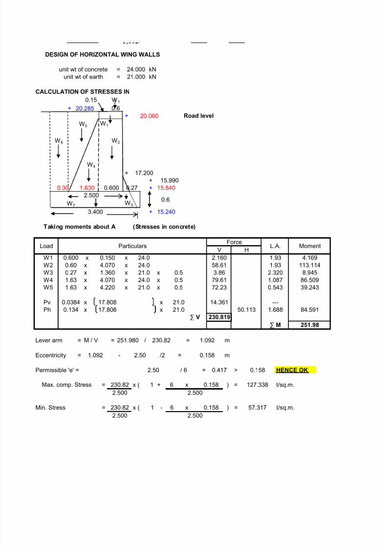
DESIGN OF HORIZONTAL WING WALLS
= kN
= kN
CALCULATION OF STRESSES IN
+
+ Road level
W1
+
++
W3
+
Taking moments about A (Stresses in concrete)
W1 x x
W2 x x
W3 x x xW4 x x x
W5 x x x
Pv x x
Ph x x
Lever arm = M / V = / = m
Eccentricity = - /2 = m
Permissible 'e' = = > HENCE OK
= x ( 1 + 6 ) = t/sq.m.
Min. Stress = x ( 1 - 6 ) = t/sq.m.
2.500 2.500
2.500 2.500
230.82 x 0.158 57.317
2.50 / 6 0.417 0.158
Max. comp. Stress 230.82 x 0.158 127.338
251.980 230.82 1.092
1.092 2.50 0.158
1.688 84.591
∑ V 230.819
∑ M 251.98
0.134 17.808 21.0 50.113
39.243
0.0384 17.808 21.0 14.361 ---
1.63 4.220 21.0 0.5 72.23 0.543
2.320 8.9451.63 4.070 24.0 0.5 79.61 1.087 86.5090.27 1.360 21.0 0.5 3.86
1.93 4.169
0.60 4.070 24.0 58.61 1.93 113.114
ForceL.A. Moment
V H
0.600 0.150 24.0 2.160
0.600 0.27
3.400 15.240
Load Particulars
W4
17.200
15.99015.840
2.5000.6
W7
0.30 1.630
20.285 0.6
20.060
W5
W6 W2
unit wt of concrete 24.000
unit wt of earth 21.000
0.15 W1

8/11/2019 UT Design (14.11.05)
http://slidepdf.com/reader/full/ut-design-141105 16/31
Taking moments about B (Stresses on soil)
W1 x x
W2 x x
W3 x x xW4 x x x
W5 x x
W6 x x
W7 x x
Pv x x
Ph x x
Lever arm = M / V = / = m
Eccentricity = - /2 = m
Permissible 'e' = = > HENCE OK
= x ( 1 + 6 ) = t/sq.m.
Min. Stress = x ( 1 - 6 ) = t/sq.m.102.961
3.40 3.400
3.40 3.400
383.20 x 0.049
3.40 / 6 0.567 0.049
Max. comp. Stress 383.20 x 0.049 122.453
670.079 383.20 1.749
1.749 3.400 0.049
∑ V 383.204
∑ M 670.079
---
0.134 17.808 21.0 - 50.113 1.928 96.618
0.0384 17.808 21.0 14.361
0.567
3.40 0.60 24.0 48.960 1.700 83.232
0.60 0.30 21.0 3.780
159.218 1.38724.0 0.50
0.150
220.783
1.63 4.22 21.0 144.451 0.843 121.821
1.63 4.070
2.23 130.696
0.27 1.360 24.0 0.50 4.406 2.620 11.545
0.60 4.070 24.0 58.61
MomentV H
0.60 0.150 24.0 2.160 2.23 4.817
Load ParticularsForce (kN)
L.A.

8/11/2019 UT Design (14.11.05)
http://slidepdf.com/reader/full/ut-design-141105 17/31
unit wt of concrete = 24.000 kN/m3
unit wt of earth = 21.000 kN/m3
unit wt of concrete = 25.000 kN/m3
The stability for the entire pier is examined for two different cases1) Canal full and stream full and
2) Canal empty but with crowd load and stream full
Case I Canal full and stream full
I. Determination of Longitudinal Moments:
Moments are reckoned about 'A' on the upstream end.
0.3 3.825
0.3
18.26
0.420 0.04
CBL 18.26
17.96
17.92
17.5017.20
25 mm dia Holding
Down Bolts at 2000 c/c
1
10
15.99
15.84
15.24
1000
PIER UNDER CANAL TROUGH
23.980
24.100
24.560
DESIGN OF PIER
The pier is subject to both longitudinal and transverse moments due to the Direct Loads, Live Loads on
water currents which determines the maximum and minimum stresses induced in the pier.
25.000
1.5 :1

8/11/2019 UT Design (14.11.05)
http://slidepdf.com/reader/full/ut-design-141105 18/31
a) Weight of bottom slab = [23.98+24.56] x 0.42 x 6
= 1529.01 kN
b) Weight of side slabs = 2 x [5.21+5.927] x [0.3+
= 603.56 kN
c) Weight of sealing coat = 0.04 x [24.1+23.98] x 6.
= 138.47 kN
d) Weight of earth cushion in the trough = 0.3 x [24.1+25] x 6.00 x
= 927.99 kN
e) Weight of water in the trough = [25+32.65] x 6.00 x 25/2
= 4323.75 kN
f) Weight of bed block under canal trough = 0.3 x 24.56 x 24
= 176.83 kN
g) Weight of rectangular portion of pier under road bridge = 5.01 x 1 x 3.485 x 24
= 370.94 kN
h)= 1.035 x 3.56 x 1 x 24
= 88.43 kN
i) Weight of triangular portion under canal trough = 2 x 4.51 x [20.06-17.50]
= 352.86 kN
j)= 2 x 4.51 x 0.3 x 1 x 24
= 64.944 kN
k)= 1.31 x [20.06-17.2] x 1 x
= 111.93 kN
l) Weight of Road Bridge: =
i) Slab : = 4.92 x 6 x 0.4 x 25
ii) Wearing coat : = 4.25 x 6 x 0.075 x 24
Weight of rectangular portion of pier between Canal trough
and foot bridge
Weight of rectangular portion [below triangular portion]under canal trou h
Weight of rectangular portion of pier between Road Bridge
and Canal Trough

8/11/2019 UT Design (14.11.05)
http://slidepdf.com/reader/full/ut-design-141105 19/31
iii) Kerbs : = 2 x 6 x 0.225 x 0.225 x
iV) Hand rails : = 2 x 6 x 120/1000
m) Weight of pier below foot bridge = 1.8 x 1 x [20.96-17.2] x
= 162.43 kN
n) Weight of pier in batter portion = 42.885 x [17.20 - 15.84]
= 1590.13 kN
o) Weight of foot bridge :
i) Slab: = 1.8 x 0.1 x 6 x 25
ii) Wearing coat : = 1.5 x 6 x 0.075 x 24
iii) Kerbs : = 2 x 0.15 x 0.225 x 6 x 2
iV) Beams : = 2 x 0.15 x 0.225 x 6 x 2
v) Haunches : = 2 x 0.5 x 0.1 x 0.1 x 6 x
vi) Crowd load : = 400 x 1.5 x 6/1000
Taking moments about 'A'

8/11/2019 UT Design (14.11.05)
http://slidepdf.com/reader/full/ut-design-141105 20/31
3.825 0.3
20.81
5.21
5.967
17.50
RCL 20.760
20.68520.285
19.985
17.20
15.99
15.84
15.24
1000
PIER UNDER ROAD BRIDGE
1272
the road, forces due to wind and

8/11/2019 UT Design (14.11.05)
http://slidepdf.com/reader/full/ut-design-141105 21/31
.00 x 25/2
.42] x 6 x 25/[2 x 2]
0 x24/2
21/2
x 1 x 24/2
24
= 295.20 kN
= 45.90 kN

8/11/2019 UT Design (14.11.05)
http://slidepdf.com/reader/full/ut-design-141105 22/31
= 15.19 kN
= 1.44 kN
4
x [1+1.272] x 24/2
= 27.00 kN
= 16.20 kN
= 10.13 kN
= 10.13 kN
= 1.50 kN
= 3.60 kN

8/11/2019 UT Design (14.11.05)
http://slidepdf.com/reader/full/ut-design-141105 23/31
I. Design of Abutment under canal trough:
[ with 50% of Hydrostatic Pressure]
Reaction of canal trough on to the abutment
= 1/2 x [(6x0.42 x 25) + (6 x 0.04 x 24) + ( 6 x 2.55 x 10)]
= 110.88 kN
18.2617.96
17.92
17.50
0.5
600
1730
1000
270 15.84
3000
15.24
3900
CALCULATIONS OF STRESSES IN CONCRETE:
Case - I with 50% hydrostatic pressure:
Taking moments about 'A', we have
Vertical (V) Horizontal (H)
1 R As calculated 110.88 - 2.23 247.26
2 W1 0.5 x 0.3 x 25 3.75 - 2.23 8.36
3 W2 0.5 x 1.36 x 24 16.32 - 2.23 36.39
4 W3 0.5 x 0.27 x 1.36 x 24 4.41 - 2.86 12.60
5 W4 0.5 x 0.46 x 24 5.52 - 1.98 10.93
6 W5 0.5 x 2.12 x 24 19.92 - 1.98 39.447 W6 0.5 x2.12 x 1.73 x 24 44.01 - 1.153 50.74
8 W7 2.23 x 2.55 x 10 56.86 - 1.115 63.40
9 W8 2.23x 0.3 x [21 - 10] 4.05 - 1.115 4.51
10 W9 0.5 x 1.73 x 2.12 x 11 20.17 - 0.577 11.64
11 Pv0.0384 x [3.11 - 0.3 ] x 11 13.58 - - -
12 Ph0.134 x [3.11 - 0.3 ] x 11 - 8.36 0.85 7.09
13 P1 0.5 x 2.35 x 24 - 28.20 2.97 83.70
14 P20.5 x 0.5 x 2.12 - 1.12 1.12 1.26
Σ V 299.473 Σ M 577.34
L.A = Σ M/ΣV
= 577.3/299.473 = 1.928
Ecentricity = 1.928 - 3/2 = 0.428
Allowable (e) 3/6 = 0.5
> 0.428
Hence no tension
Max and Min stresses = 325.997/3.0 x [1± (6 x 0.482)/3.0]
[Compressive] 110.62 kN/m2 (Max)
3.91 kN/m2 (Min)
CALCULATIONS OF STRESSES IN SOIL:
Taking moments about 'B'
Vertical (V) Horizontal (H)Sl.No Load Description
Sl.No Load Description
Lever arm
m
17.20
Lever Arm
(m)
Moment
kN-m
Force (kN) Moment
kN-m
Force (kN)
Design of Abutments page23

8/11/2019 UT Design (14.11.05)
http://slidepdf.com/reader/full/ut-design-141105 24/31
1 R As calculated 110.88 - 2.53 280.53
2 W1 0.5 x 0.3 x 25 3.75 - 2.53 9.49
3 W2 0.5 x 1.36 x 24 16.32 - 2.53 41.29
4 W3 0.5 x 0.27 x 1.36 x 24 4.41 - 3.16 13.92
5 W4 0.5 x 0.46 x 24 5.52 - 2.28 12.59
6 W5 0.5 x 1.66 x 24 19.92 - 2.28 45.42
7 W6 0.5 x 2.12 x 1.73 x 24 44.01 - 1.453 63.95
8 W7 2.23 x 2.55 x 10 56.87 - 1.415 80.469 W8 2.23x 0.3 x [21 - 10] 7.36 - 1.415 10.41
10 W9 0.5 x 1.73 x 2.12 x 11 20.17 - 0.877 17.69
11 W10 0.3 x 2.42 x11 + 0.3 x 2.8 x 10 18.81 - 0.15 2.82
12 W11 3.9 x 0.6 x 24 56.16 - 1.95 109.51
13 PV0.0384 x [3.02 - 0.3 ] x 11 3.81 - - -
14 Ph 0.134 x [3.022 - 0.3
2] x 11 - 14.12 1.088 15.37
15 P1 0.5 x 2.72 x 2.8 x 10 - 38.08 1.36 51.79
16 P2 0.5 x 0.5 x 2.722
- 1.85 1.85 3.42
ΣV 367.99 ΣM 758.66
Design of Abutments page24
8/11/2019 UT Design (14.11.05)
http://slidepdf.com/reader/full/ut-design-141105 25/31
L .A = 2.06
Ecentricity = 2.07 - 3.9/2
= 0.12 m
Allowable (e) 3.9/6.00 = 0.65 m
> 0.12 m
Hence no tension
Max and Min Stresses = 400.97/3.9 x [1± (6 x 0.12)/3.9][Compressive] = 121.79 kN/mm
2(Max)
= 83.83 kN/mm2(Min)
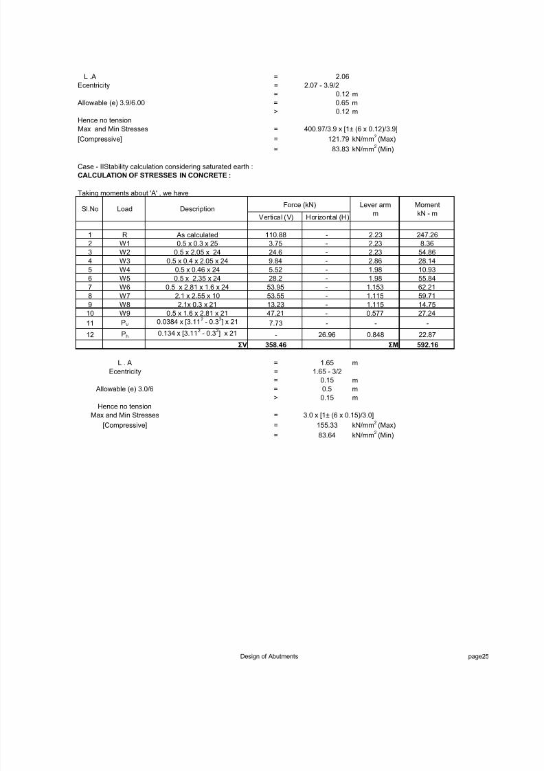
Case - IIStability calculation considering saturated earth :
CALCULATION OF STRESSES IN CONCRETE :
Taking moments about 'A' , we have
Vertical (V) Horizontal (H)
1 R As calculated 110.88 - 2.23 247.26
2 W1 0.5 x 0.3 x 25 3.75 - 2.23 8.36
3 W2 0.5 x 2.05 x 24 24.6 - 2.23 54.86
4 W3 0.5 x 0.4 x 2.05 x 24 9.84 - 2.86 28.14
5 W4 0.5 x 0.46 x 24 5.52 - 1.98 10.93
6 W5 0.5 x 2.35 x 24 28.2 - 1.98 55.84
7 W6 0.5 x 2.81 x 1.6 x 24 53.95 - 1.153 62.21
8 W7 2.1 x 2.55 x 10 53.55 - 1.115 59.71
9 W8 2.1x 0.3 x 21 13.23 - 1.115 14.75
10 W9 0.5 x 1.6 x 2.81 x 21 47.21 - 0.577 27.24
11 PV0.0384 x [3.11
2 - 0.3
2] x 21 7.73 - - -
12 Ph0.134 x [3.11
2 - 0.3
2] x 21 - 26.96 0.848 22.87
ΣV 358.46 ΣM 592.16
L . A = 1.65 m
Ecentricity = 1.65 - 3/2
= 0.15 m
Allowable (e) 3.0/6 = 0.5 m> 0.15 m
Hence no tension
Max and Min Stresses = 3.0 x [1± (6 x 0.15)/3.0]
[Compressive] = 155.33 kN/mm2(Max)
= 83.64 kN/mm2(Min)
Force (kN) Lever arm
m
Moment
kN - mSl.No Load Description
Design of Abutments page25

8/11/2019 UT Design (14.11.05)
http://slidepdf.com/reader/full/ut-design-141105 26/31
CALCULATION OF STRESSES IN SOIL :
Take moments about 'B'
Vertical (V) Horizontal (H)
1 R As calculated 110.88 - 2.53 280.532 W1 0.5 x 0.3 x 25 3.75 - 2.53 9.49
3 W2 0.5 x 2.05 x 24 24.6 - 2.53 62.24
4 W3 0.5 x 0.4 x 2.05 x 24 9.84 - 3.16 31.09
5 W4 0.5 x 0.46 x 24 5.52 - 2.28 12.59
6 W5 0.5 x 2.35 x 24 28.2 - 2.28 64.30
7 W6 0.5 x 2.81 x 1.6 x 24 53.95 - 3.16 170.49
8 W7 2.1 x 2.55 x 10 53.55 - 2.28 122.09
9 W8 2.1x 0.3 x [21 - 10] 6.93 - 2.28 15.80
10 W9 0.5 x 1.6 x 2.81 x 21 47.21 - 1.453 68.59
11 W10 0.3 x 3.11 x11 + 0.3 x 2.85 x 10 18.81 - 0.15 2.82
12 W11 3.9 x 0.6 x 24 56.16 - 1.95 109.51
13 PV 0.0384 x [3.11 - 0.3 ] x 21 7.73 - - -
14 Ph 0.134 x [3.112 - 0.3
2] x 21 - 26.96 1.088 29.34
ΣV 427.13 ΣM 978.87
L .A = 2.29
Ecentricity = 2.29 - 3.9/2
= 0.34 m
Allowable (e) 3.9/6.00 = 0.65 m
> 0.34 m
Hence no tension
Max and Min Stresses = 427.13/3.9 x [1± (6 x 0.34)/3.9]
[Compressive] = 156.59 kN/mm2(Max)
= 49.03 kN/mm2(Min)
Lever arm
( m)
Force (kN)DescriptionLoadSl.No Moment
kN-m
Design of Abutments page26

8/11/2019 UT Design (14.11.05)
http://slidepdf.com/reader/full/ut-design-141105 27/31
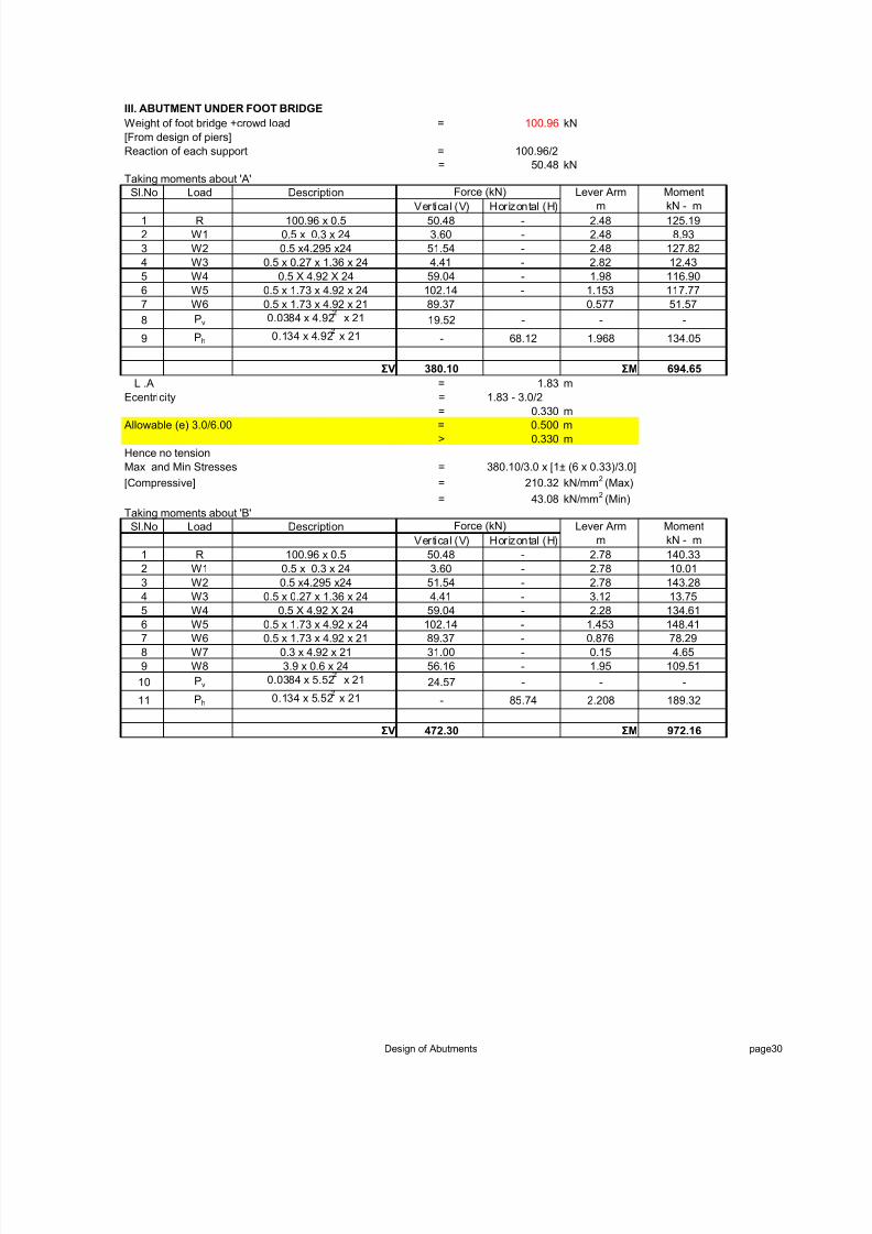
II. DESIGN OF ABUTMENT UNDER ROAD BRIDGE
.Reaction for clear span of 5.00m
a) Weight of slab = 6 x 4.92 x 0.4 x 25
= 295.20 kN
b) Weight of wearing coat = 6 x 4.25 x 0.075 x 24
= 45.9 kN
c) Weight of kerbs = 2 x 6 x 0.2875 x4.25 x 25= 366.56 kN
d) Weigth of Hand Rails =
(assuming 120 kg/m = 2 x 6 x 0.15
= 1.80 kN
Total Load = 524.95 kN
a) Dead load reaction = 663.56/2
= 262.48 kN/m
b) Change in live load reaction due to braking effect. The braking force will be acting at a height of 1.20m above Roa
Level arm = 1.2 + 0.475
= 1.675 m
Change in vertical direction = [20/100] x [11.4+11.4+2.7] x [1.675/5.357]
= 1.595 t
= 15.95 kN
Taking moments about 'B'
R A x 5.357 = 11.4 x 5.357 + 11.4 x 4.157 + 2.7 x 0.957
R A = 111.044/5.357
= 20.729 t
= 207.29 kN
Live Load reaction = 207.29 kN
c) Impact load reaction = 207.29 x 0.396 x [X]
Where [X] is the impact factor multiplying factor which depends upon the height of abutment.
Height of abutment below bed block = 17.2 - 15.15
2.05 m
As the height of the abutment below the bed block is more than 3.0m, hence the impact multying factor is zero.
Therefore there is no change in Live load reaction.
Total Reaction = 485.72 kN
Length of abutment = 1.92 mReaction per m run [R] = 252.98 kN/m
As the span is less than 8m, no frictional forces due to temperature variation are considered.
Horizontal force due to braking effect 'Bk'
Bk = [20/1000] x [11.4+11.4+2.7]
= 0.51 t
Braking force felt by each bearing = 0.51/2
= 0.26 kN
Force per m run = 0.26/4.92
= 0.052 t
= 0.52 kN
Design of Abutments page27

8/11/2019 UT Design (14.11.05)
http://slidepdf.com/reader/full/ut-design-141105 28/31
CALCULATION OF STRESSES IN CONCRETE:
Taking moments about 'A', i.e., + 17.20
Sl.No Load Description
Vertical (V) Horizontal (H)
1 R As calculated 252.98 - 2.645 669.13
2 W1 0.5 x 0.3 x 25 3.75 - 2.645 9.923 W2 0.5 x2.985 x24 35.82 - 2.645 94.74
4 W3 0.5 x 3.685 x 24 44.22 - 2.145 94.85
5 W4 0.5 x 1.895 x 3.685 x 24 83.80 - 1.263 105.84
6 W5 0.5 x 1.895 x 3.685 x 21 73.32 - 0.632 46.34
7 Pv0.0384 x 3.685 x 21 10.95 - - -
8 Ph0.134 x 3.685 x 21 - 38.21 1.424 54.41
9 Bt As calculated - 0.52 3.085 1.60
ΣV 504.84 ΣM 1076.83
L .A = 2.13 m
Ecentricity = 2.13 - 3.095/2
= 0.743 m
Allowable (e) 3.095/6.00 = 0.516 m
> 0.743 m
Hence no tensionMax and Min Stresses = 427.13/3.9 x [1± (6 x 0.34)/3.9]
[Compressive] = 156.59 kN/mm2(Max)
= 49.03 kN/mm2(Min)
Taking moments about 'A', i.e., + 15.84
Sl.No Load Description
Vertical (V) Horizontal (H)
1 R As calculated 252.98 - 3.48 880.36
2 W1 0.5 x 0.3 x 25 3.75 - 3.48 13.05
3 W2 0.5 x4.345 x24 52.14 - 3.48 181.45
4 W3 0.5 x 0.27 x 1.36 x 24 4.41 - 3.82 16.83
5 W4 0.5 x 5.12 x 24 61.44 - 2.98 183.09
6 W5 0.5 x 2.73 x 5.12 x 24 167.73 - 1.82 305.27
7 W6 0.5 x 2.73 x 5.12 x 21 146.76 0.91 133.56
8 Pv0.0384 x 5.12 x 21 21.14 - - -
9 Ph 0.134 x 5.12 x 21 - 73.77 1.968 145.17
10 Bt As calculated - 0.52 4.145 2.16
ΣV 710.35 ΣM 1860.94
Force (kN) Lever Arm
m
Moment
kN - m
Lever Arm
m
Moment
kN - m
Force (kN)
Design of Abutments page28

8/11/2019 UT Design (14.11.05)
http://slidepdf.com/reader/full/ut-design-141105 29/31
L .A = 2.62 m
Ecentricity = 2.62 - 4/2
= 0.620 m
Allowable (e) 4/6.00 = 0.667 m
> 0.620 m
Hence no tension
Max and Min Stresses = 710.35/4 x [1± (6 x 0.62)/4.0]
[Compressive] = 342.68 kN/mm2 (Max)
= 12.50 kN/mm2(Min)
CALCULATION OF STRESSES ON SOIL
Taking moments about 'C'
Sl.No Load Description
Vertical (V) Horizontal (H)
1 R As calculated 252.98 - 3.78 956.26
2 W1 0.5 x 0.3 x 25 3.75 - 3.78 14.18
3 W2 0.5 x4.345 x24 52.14 - 3.78 197.09
4 W3 0.5 x 0.27 x 1.36 x 24 4.41 - 4.12 18.15
5 W4 0.5 x 5.12 x 24 61.44 - 3.28 201.52
6 W5 0.5 x 2.73 x 5.12 x 24 167.73 - 2.12 355.59
7 W6 0.5 x 2.73 x 5.12 x 21 146.76 1.21 177.59
8 W7 0.3 x 5.12 x 21 32.26 0.15 4.84
9 W8 4.9 x 0.6 x 24 70.56 2.45 172.87
10 Pv0.0384 x 5.12 x 21 21.14 - - -
11 Ph0.134 x 5.12 x 21 - 73.77 1.968 145.17
12 Bt As calculated - 0.52 4.145 2.16
ΣV 813.17 ΣM 2245.41
L .A = 2.76 m
Ecentricity = 2.76 - 4.9/2
= 0.310 m
Allowable (e) 4.9/6.00 = 0.817 m
> 0.310 m
Hence no tension
Max and Min Stresses = 813.17/4.9 x [1± (6 x 0.31)/4.9]
[Compressive] = 228.95 kN/mm2(Max)
= 102.96 kN/mm
2
(Min)
Force (kN) Lever Arm
m
Moment
kN - m
Design of Abutments page29
8/11/2019 UT Design (14.11.05)
http://slidepdf.com/reader/full/ut-design-141105 30/31

8/11/2019 UT Design (14.11.05)
http://slidepdf.com/reader/full/ut-design-141105 31/31
L .A = 2.06 m
Ecentricity = 2.06 - 3.9/2
= 0.110 m
Allowable (e) 3.9/6.00 = 0.650 m
> 0.110 m
Hence no tension
Max and Min Stresses = 472.3/3.9 x [1± (6 x 0.11)/3.9]
[Compressive] = 141.60 kN/mm2 (Max)
= 100.61 kN/mm2(Min)