The use of replicas in the measurement of machine elements with … · topography analysis obtained...
3
MECHANIK NR 11/2018 How to cite this article: Authors: Marek Hawryluk, Marek Kuran, Jacek Ziemba Title of article: „Zastosowanie replik do kontroli części z wykorzystaniem stykowych pomiarów współrzędnościowych” (“The use of replicas in the measurement of machine elements with use of contact coordinate measurements”) Mechanik, Vol. 91, No. 11 (2018): pages 958–960 DOI: https://doi.org/10.17814/mechanik.2018.11.169 The use of replicas in the measurement of machine elements with use of contact coordinate measurements Zastosowanie replik do kontroli części z wykorzystaniem stykowych pomiarów współrzędnościowych MAREK HAWRYLUK MAREK KURAN JACEK ZIEMBA * Modern technology allows to design and manufacture machine elements with complex geometry that makes it difficult or even impossible to use coordinate measuring machines for verification of them. The article presents the possibility of using replicas of product geometry to control geometric features using contact measurements on a coordinate machine. KEYWORDS: coordinate masurements, replicas of geometric features The most time-consuming stage in the production process is verification of the correctness of the finished product. With the current tendency to accelerate production, one of the ways to shorten the control time of the geometry of the manufactured element is the use of coordinate measuring technique. In order to gain access to the geometry of the product hidden inside, it is possible to make a replica of this product and measure its geometry. This technique is used especially when measuring the geometric structure of the surface. This is also facilitated by the functions that the software of contemporary profilometers is equipped with, which offer the possibility of topography analysis obtained by measuring replicas of the geometric structure of the product surface. Materials used to make such replicas must be characterized by high stiffness, low deformability of the surface and slight changes in geometry during curing. Such properties are advantages when measuring, among others features of the surface structure of the product, but make it impossible to make replicas of the complex geometry of the product due to the inability to extract a replica from reconstructed e.g. holes, internal threads or spline without destroying it. It is then necessary to perform a partial re-files of the geometric element [1], not allowing for a complete verification of the correctness of its execution, or searching for materials allowing a significant distortion of the ready replica while removing it from the replicated element. Such possibilities are offered, among others two- component plastics chemically hardened Plastiform, depending on the intended use, characterized by a good filling of the reconstructed geometry, considerable elasticity allowing the removal of the replica from the measured element without its destruction and good replication of surface unevenness. The main purpose of these masses, however, is to use them in optical measurements, using microscopes and projectors [2], to measure selected features of the replica in its entirety or cross-sections made with a special double knife supplied by the mass producer. Scope of research Replicas made of Rivelec’s Plastiform were measured. For the tests, masses were selected that can be removed from the repaired elements even with considerably complicated geometry. Such capacity was defined by the manufacturer as the RC (removal constraint) value determined from the dependence: = (1 − ) ∙ 100% (1) where: D min – the smallest diameter of the hole through which the replica is to be removed, D max – the largest diameter of the replicated element. In order to be able to remove a replica from a complicated geometry hole, the RC value should be greater than 0%. This condition is met by the masses listed in the table. In addition, the manufacturer gives nominal hardness values of individual materials in the Shore A scale. In the case of contact measurements, it is advantageous to use a material with as high a hardness as possible, which translates into a lower susceptibility of the material surface to deformation during contact measurements. TABLE. Plastiform masses used in research Mass F20 D.A.V. F30 E.S.A.D. F40 B.R.A.D. P25 J.A.D. P35 S.O.F.T. RC, % 30 20 35 20 20 Shore A, Sh 20 20 40 25 35 * Dr hab. inż. Marek Hawryluk ([email protected]), dr inż. Marek Kuran ([email protected]), dr inż. Jacek Ziemba ([email protected]) – Katedra Obróbki Plastycznej i Metro- logii Politechniki Wrocławskiej
Transcript of The use of replicas in the measurement of machine elements with … · topography analysis obtained...
MECHANIK NR 11/2018
How to cite this article:
Authors: Marek Hawryluk, Marek Kuran, Jacek Ziemba
Title of article: „Zastosowanie replik do kontroli części z wykorzystaniem stykowych pomiarów współrzędnościowych” (“The use of replicas in the measurement of machine elements with use of contact coordinate measurements”)
Mechanik, Vol. 91, No. 11 (2018): pages 958–960
DOI: https://doi.org/10.17814/mechanik.2018.11.169
The use of replicas in the measurement of machine
elements with use of contact coordinate measurements
Zastosowanie replik do kontroli części z wykorzystaniem stykowych pomiarów współrzędnościowych
MAREK HAWRYLUK MAREK KURAN JACEK ZIEMBA *
Modern technology allows to design and manufacture machine elements with complex geometry that makes it difficult or even impossible to use coordinate measuring machines for verification of them. The article presents the possibility of using replicas of product geometry to control geometric features using contact measurements on a coordinate machine. KEYWORDS: coordinate masurements, replicas of geometric features
The most time-consuming stage in the production process is verification of the correctness of the finished product. With the current tendency to accelerate production, one of the ways to shorten the control time of the geometry of the manufactured element is the use of coordinate measuring technique. In order to gain access to the geometry of the product hidden inside, it is possible to make a replica of this product and measure its geometry.
This technique is used especially when measuring the geometric structure of the surface. This is also facilitated by the functions that the software of contemporary profilometers is equipped with, which offer the possibility of topography analysis obtained by measuring replicas of the geometric structure of the product surface.
Materials used to make such replicas must be characterized by high stiffness, low deformability of the surface and slight changes in geometry during curing. Such properties are advantages when measuring, among others features of the surface structure of the product, but make it impossible to make replicas of the complex geometry of the product due to the inability to extract a replica from reconstructed e.g. holes, internal threads or spline without destroying it. It is then necessary to perform a partial re-files of the geometric element [1], not allowing for a complete verification of the correctness of its execution, or searching for materials allowing a significant distortion of the ready replica while removing it from the replicated element.
Such possibilities are offered, among others two-component plastics chemically hardened Plastiform, depending on the intended use, characterized by a good filling of the reconstructed geometry, considerable elasticity allowing the removal of the replica from the measured element without its destruction and good replication of surface unevenness. The main purpose of these masses, however, is to use them in optical measurements, using microscopes and projectors [2], to measure selected features of the replica in its entirety or cross-sections made with a special double knife supplied by the mass producer.
Scope of research
Replicas made of Rivelec’s Plastiform were measured.
For the tests, masses were selected that can be removed from the repaired elements even with considerably complicated geometry. Such capacity was defined by the manufacturer as the RC (removal constraint) value determined from the dependence:
𝑅𝐶 = (1 −𝐷𝑚𝑖𝑛
𝐷𝑚𝑎𝑥) ∙ 100% (1)
where: Dmin – the smallest diameter of the hole through which the replica is to be removed, Dmax – the largest diameter of the replicated element.
In order to be able to remove a replica from a
complicated geometry hole, the RC value should be greater than 0%. This condition is met by the masses listed in the table. In addition, the manufacturer gives nominal hardness values of individual materials in the Shore A scale. In the case of contact measurements, it is advantageous to use a material with as high a hardness as possible, which translates into a lower susceptibility of the material surface to deformation during contact measurements.
TABLE. Plastiform masses used in research
Mass F20
D.A.V. F30
E.S.A.D. F40
B.R.A.D. P25
J.A.D. P35
S.O.F.T.
RC, %
30 20 35 20 20
Shore A,
Sh 20 20 40 25 35
* Dr hab. inż. Marek Hawryluk ([email protected]), dr
inż. Marek Kuran ([email protected]), dr inż. Jacek Ziemba
([email protected]) – Katedra Obróbki Plastycznej i Metro-
logii Politechniki Wrocławskiej
MECHANIK NR 11/2018
The Mitutoyo setting ring hole replicas with nominal diameter D = 19.997 mm were measured. The replicas were made on a ring placed on a flat surface of the measuring projector's mirror, in order to ensure the possibly similar straight-axis deviation of their axis in relation to the surface to be the base during further measurements.
Replica measurements were carried out on the Mitutoyo Crysta Plus-M544 co-ordinate machine. The outer diameter of the replica set directly on the measuring plate of the CMM machine was measured. The mean was determined for four types of approximation of the smallest squares LSCI (Gauss), minimal zone MZCI (Chebyshew), element described MICI and element inscribed MCCI, based on measured on the surface of the replica 12 points, evenly distributed on its circumference at a height of 5 mm from the base surface, which is half of its height. As a reference for the measurement results, the values obtained during the measurement of the standard ring were used, using the presented procedure diagram during the measurement.
A Renishaw TP20 probe was used, with a tip ending in a ball with a diameter of Ø3 mm, with a standard measuring force. In order to determine the possible influence of the measuring direction on the measuring force, this force was measured in the direction of the +X, -X and +Y, -Y axes as well as the +Z axis. The measurements were made with a digital AST force gauge, equipped with a strain gauge compressor of the range 0÷100 N and a digital step 0.01 N.
The hardness of the hardened masses was also measured using a Shore type A hardness tester to determine the possible differences in relation to the values given by the manufacturer and their effect on the measurement result of the replicas.
Test results
Preliminary examinations included measurement of the
pressure force and the hardness of the mass specimens used to make the replicas. Fig. 1 presents the results of the measurement of the TP20 probe's measuring force in different directions, consistent with the axis of the coordinate system of the measuring machine.
X
Y
Z
0,10,2
0,20,1
0,2
0,1
0,1
0,2
0,2
0,1
[N]
[N]
[N]
Fig. 1. Values of the TP20 probe measuring force with a standard measuring force, depending on the direction of measurement
The results presented are the average value from the
series of 10 measurements made for each direction of measurement of the coordinate measuring machine. As can be seen, the values of the measuring pressure – both in the direction of ±X and in the direction of ±Y – are close to and do not exceed the value of F±X ≈ F±Y = 0.1 N. They correspond to Renishaw data [3], which for the probe with standard measuring pressure gives the value of force F±XYnom = 0.08 N. in the measurement directions ±XY.
Additionally, pressure measurements in the +Z axis were made (it was not used in the tests). As you can see in fig. 1, the pressure in this direction is slightly higher than 0.2 N. This is a result less than specified by the manufacturer, which for this direction of measurement and for this probe gives the maximum pressure at F±Znom = 0.75 N. The
obtained results confirm that the measuring pressure of the TP20 probe in the directions of the machine axis of the coordinate system in the XY plane does not exceed the values declared by the manufacturer. It can therefore be concluded that in the case of measurements in other directions, this value will also not be exceeded, despite the triangularity of the contact force characteristic for this type of probes [4].
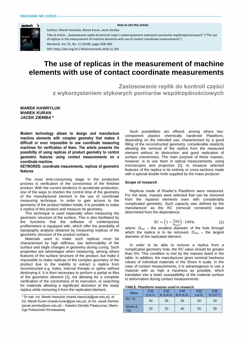
Fig. 2. shows the results of Shore type A replicas. The results were compared with the nominal values given by the mass producer, Rivelec.
Fig. 2. Shore A-type hardness test results of replicas depending on the mass used compared to nominal values
The results presented are an average value from a series
of 10 measurements made for each replica at various points on their surface. As you can see, the hardness of replicas made of F40 B.R.A.D. and P35 S.O.F.T. corresponds to nominal values [5] – they slightly exceed or slightly exceed the values given by the manufacturer; respectively:
38A °Sh to 40A °Sh for mass F40 B.R.A.D.,
36A °Sh to 35A °Sh for P35 S.O.F.T. In the case of masses with lower declared hardness, the
values measured for the samples were clearly greater than those declared by the manufacturer, respectively:
27A °Sh to 20A °Sh for mass F 20 D.A.V.,
24A °Sh to 20A °Sh for mass F30 E.S.A.D.,
33A °Sh to 25A °Sh for mass P25 J.A.D. The higher hardness of the samples in the case of
contact measurements is a favorable phenomenon.
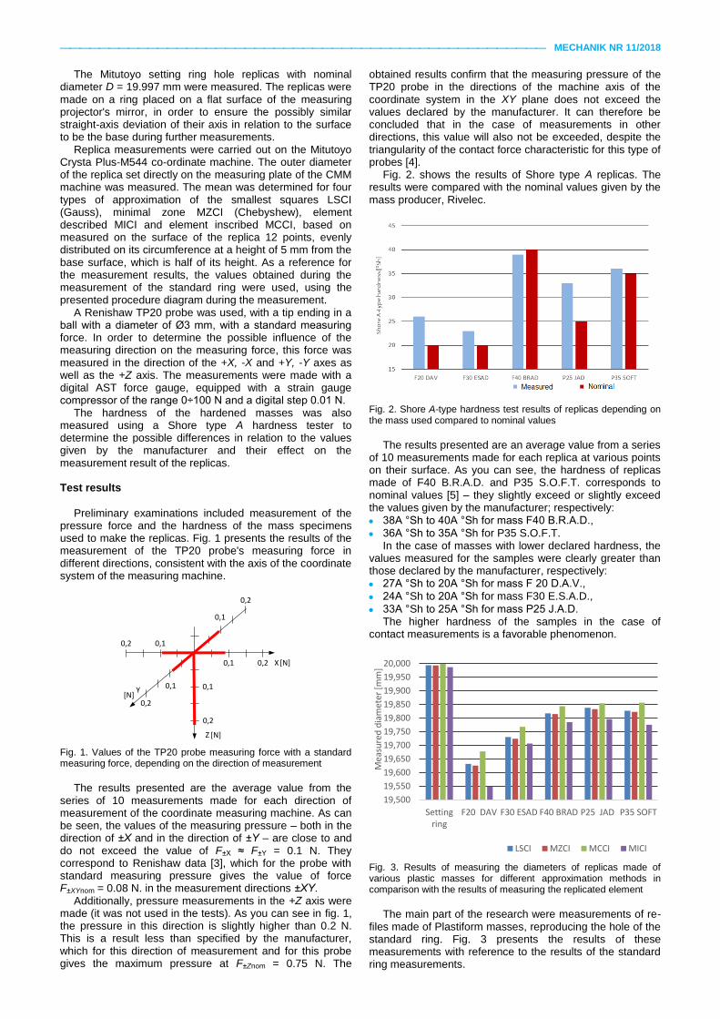
Fig. 3. Results of measuring the diameters of replicas made of various plastic masses for different approximation methods in comparison with the results of measuring the replicated element
The main part of the research were measurements of re-
files made of Plastiform masses, reproducing the hole of the standard ring. Fig. 3 presents the results of these measurements with reference to the results of the standard ring measurements.
19,500
19,550
19,600
19,650
19,700
19,750
19,800
19,850
19,900
19,950
20,000
Settingring
F20 DAV F30 ESAD F40 BRAD P25 JAD P35 SOFT
Mea
sure
d d
iam
eter
[m
m]
LSCI MZCI MCCI MICI
MECHANIK NR 11/2018
The results presented are an average value from a series of 10 measurements made for each replica and for each method of approximation of the cross-section outline. As can be seen, the measurement results of diameters measured for replicas differ from the measured value of the replicated hole. These differences depend on the approximation method used: 0.156÷0.176 mm for the LSCI circle, 0.155÷0.175 mm for the MZCI circle, 0.143÷0.155 mm for the MCCI circle and 0.191÷0.211 mm for the MICI circle for the F40 B.R.A.D., P25 J.A.D. and P35 S.O.F.T.
For F20 masses D.A.V. and F30 E.S.A.D. the differences are: 0.263÷0.362 mm for the LSCI circle, 0.269÷0.367 mm for the MZCI circle, 0.231÷0.321 mm for the MCCI circle and 0.280÷0.439 mm for the MICI circle. As can be seen, the differences in the measurement results change in a manner proportional to the measured values of the hardness of individual samples and are similar for the F40 mass B.R.A.D., P25 J.A.D. and P35 S.O.F.T., the Shore hardness of which is measured at a similar level and increases with decreasing measured hardness for F20 masses of D.A.V. and F30 E.S.A.D.
After comparing the results of measurements of the replicated element with the nominal value of its diameter, the differences amount to 0.002÷0.004 mm depending on the approximation used, which is in the error of the measurement used for the CMM, for which the manufacturer determined the maximum permissible value error at the MPE level = 0.0036 mm for the dimension corresponding to the nominal diameter of the measured element.
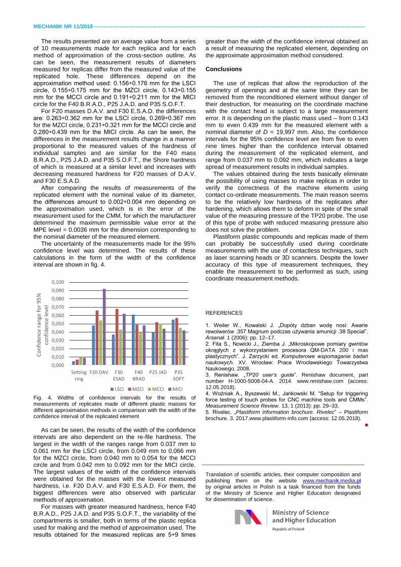
The uncertainty of the measurements made for the 95% confidence level was determined. The results of these calculations in the form of the width of the confidence interval are shown in fig. 4.
Fig. 4. Widths of confidence intervals for the results of measurements of replicates made of different plastic masses for different approximation methods in comparison with the width of the confidence interval of the replicated element
As can be seen, the results of the width of the confidence
intervals are also dependent on the re-file hardness. The largest in the width of the ranges range from 0.037 mm to 0.061 mm for the LSCI circle, from 0.049 mm to 0.066 mm for the MZCI circle, from 0.040 mm to 0.054 for the MCCI circle and from 0.042 mm to 0.092 mm for the MICI circle. The largest values of the width of the confidence intervals were obtained for the masses with the lowest measured hardness, i.e. F20 D.A.V. and F30 E.S.A.D. For them, the biggest differences were also observed with particular methods of approximation.
For masses with greater measured hardness, hence F40 B.R.A.D., P25 J.A.D. and P35 S.O.F.T., the variability of the compartments is smaller, both in terms of the plastic replica used for making and the method of approximation used. The results obtained for the measured replicas are 5÷9 times
greater than the width of the confidence interval obtained as a result of measuring the replicated element, depending on the approximate approximation method considered.
Conclusions
The use of replicas that allow the reproduction of the geometry of openings and at the same time they can be removed from the reconditioned element without danger of their destruction, for measuring on the coordinate machine with the contact head is subject to a large measurement error. It is depending on the plastic mass used – from 0.143 mm to even 0.439 mm for the measured element with a nominal diameter of D = 19,997 mm. Also, the confidence intervals for the 95% confidence level are from five to even nine times higher than the confidence interval obtained during the measurement of the replicated element, and range from 0.037 mm to 0.092 mm, which indicates a large spread of measurement results in individual samples.
The values obtained during the tests basically eliminate the possibility of using masses to make replicas in order to verify the correctness of the machine elements using contact co-ordinate measurements. The main reason seems to be the relatively low hardness of the replicates after hardening, which allows them to deform in spite of the small value of the measuring pressure of the TP20 probe. The use of this type of probe with reduced measuring pressure also does not solve the problem.
Plastiform plastic compounds and replicas made of them can probably be successfully used during coordinate measurements with the use of contactless techniques, such as laser scanning heads or 3D scanners. Despite the lower accuracy of this type of measurement techniques, they enable the measurement to be performed as such, using coordinate measurement methods.
REFERENCES 1. Weiler W., Kowalski J. „Dopóty dzban wodę nosi: Awarie rewolwerów .357 Magnum podczas używania amunicji .38 Special”. Arsenał. 1 (2006): pp. 12–17. 2. Fita S., Nowicki J., Ziemba J. „Mikroskopowe pomiary gwintów okrągłych z wykorzystaniem procesora QM-DATA 200 i mas plastycznych”. J. Zarzycki ed. Komputerowe wspomaganie badań naukowych. XV. Wrocław: Prace Wrocławskiego Towarzystwa Naukowego, 2008. 3. Renishaw. „TP20 user’s guide”. Renishaw document, part number H-1000-5008-04-A. 2014. www.renishaw.com (access: 12.05.2018). 4. Woźniak A., Byszewski M., Jankowski M. “Setup for triggering force testing of touch probes for CNC machine tools and CMMs”. Measurement Science Review. 13, 1 (2013): pp. 29–33. 5. Rivelec. „Plastiform information brochure. Rivelec” – Plastiform brochure. 3. 2017.www.plastiform-info.com (access: 12.05.2018).
■
Translation of scientific articles, their computer composition and publishing them on the website www.mechanik.media.pl by original articles in Polish is a task financed from the funds of the Ministry of Science and Higher Education designated for dissemination of science.
0,000
0,010
0,020
0,030
0,040
0,050
0,060
0,070
0,080
0,090
0,100
Settingring
F20 DAV F30ESAD
F40BRAD
P25 JAD P35SOFT
Co
nfi
den
ce r
ange
fo
r 9
5%
co
nfi
den
ce le
vel
LSCI MZCI MCCI MICI