Proposal of the new concept of the Stirling engine
6
32 Scientific Journals 35(107) Scientific Journals Zeszyty Naukowe Maritime University of Szczecin Akademia Morska w Szczecinie 2013, 35(107) pp. 32–37 2013, 35(107) s. 32–37 ISSN 1733-8670 Proposal of the new concept of the Stirling engine Marek Jaśkiewicz 1 , Wojciech Sadkowski 1 , Mateusz Marciniewski 1 , Krzysztof Olejnik 2 , Józef Stokłosa 2 1 Kielce University of Technology, Faculty of Mechatronics and Machine Building Department Vehicles and Transport 25-314 Kielce, aleja Tysiąclecia Państwa Polskiego 7 e-mail: {m.jaskiewicz; wsadkowski; mmarciniewski}@tu.kielce.pl 2 University of Economics and Innovation in Lublin 20-209 Lublin, ul. Projektowa 4, e-mail: {krzysztof.olejnik2; stoklosa.j}@gmail.com Key words: Stirling engine, displacer, cam mechanism, regenerator Abstract The article sets forth the new concept of structure of the Stirling engine. Specific realizations of that idea have been discussed. The modification consists in replacing the crank system with the cam mechanism. As a result, the stages of heating and cooling of working gas are longer and transitory stages are shorter. The aim is to obtain higher efficiency in relation to the already existing solutions and to simplify the engine structure. The visualisation of its structure and the principle of operation have been presented. The proper shaping of the cam mechanism allowed for the change of the significant parameters influencing its efficiency. The use of such type of engine allows for the use of heat energy lost in many technological processes and installations. Introduction Robert Stirling invented the first engine of such type and patented it in 1816. The name of the whole family of Stirling engines comes from his name [1]. The principle of operation of that engine consists in the increase of pressure of working gas placed in the heated zone, as a result of which, mechanical work is done connected with the relocation of the working piston. Then, the piston called displacer displaces the working gas to the cooling zone where the gas decreases its volume, and the work- ing piston moves back. Stirling engine is a reversi- ble machine. It means that it can process both ther- mal energy into mechanical energy, and work as a cooling or heating machine powered with me- chanical energy. The inventiveness of the new con- cept of the engine consists in the use of the cam mechanism instead of the crank system in a way increasing engine efficiency and simplifying its structure. Comparing the proposed engine with other Stirling engines In known varieties of Stirling engines, the crank system or a system working on a similar basis, cou- pling the movement of the piston with the move- ment of the displacer, occurs the most frequently. In Stirling engines the heat exchange is most in- tense when the displacer is in its extreme positions. In classic Stirling engines, such a situation occurs for short moments during the cycle of engine opera- tion [2]. The disadvantage limiting the efficiency of classic Stirling engines is a short time of intense heat exchange. Figure 1 presents the diagram of structure of the Stirling engine. In order to extend the time of intense heat exchange, the time during which the displacer is in extreme positions should be ex- tended. Achieving such an effect was possible thanks to the use in the proposed engine the cam mechanism instead of the crank system. Such a change creates the possibility of the better use of heat and the improvement of engine efficiency. It also allowed to simplify significantly its structure. In the simplest version, it has only one movable element. Another disadvantage of the majority of known varieties of Stirling engines is the necessity to seal many movable elements. In the proposed engine, there is only one such seal (piston seal). The simpler structure allows for: the improvement
Transcript of Proposal of the new concept of the Stirling engine
32 Scientific Journals 35(107)
Scientific Journals Zeszyty Naukowe Maritime University of Szczecin Akademia Morska w Szczecinie
2013, 35(107) pp. 32–37 2013, 35(107) s. 32–37 ISSN 1733-8670
Proposal of the new concept of the Stirling engine
Marek Jaśkiewicz1, Wojciech Sadkowski1, Mateusz Marciniewski1, Krzysztof Olejnik2, Józef Stokłosa2 1 Kielce University of Technology, Faculty of Mechatronics and Machine Building
Department Vehicles and Transport 25-314 Kielce, aleja Tysiąclecia Państwa Polskiego 7 e-mail: {m.jaskiewicz; wsadkowski; mmarciniewski}@tu.kielce.pl 2 University of Economics and Innovation in Lublin
20-209 Lublin, ul. Projektowa 4, e-mail: {krzysztof.olejnik2; stoklosa.j}@gmail.com
Key words: Stirling engine, displacer, cam mechanism, regenerator
Abstract The article sets forth the new concept of structure of the Stirling engine. Specific realizations of that idea have
been discussed. The modification consists in replacing the crank system with the cam mechanism. As a result,
the stages of heating and cooling of working gas are longer and transitory stages are shorter. The aim is to
obtain higher efficiency in relation to the already existing solutions and to simplify the engine structure. The
visualisation of its structure and the principle of operation have been presented. The proper shaping of the
cam mechanism allowed for the change of the significant parameters influencing its efficiency. The use of
such type of engine allows for the use of heat energy lost in many technological processes and installations.
Introduction
Robert Stirling invented the first engine of such
type and patented it in 1816. The name of the whole
family of Stirling engines comes from his name [1].
The principle of operation of that engine consists in
the increase of pressure of working gas placed in
the heated zone, as a result of which, mechanical
work is done connected with the relocation of the
working piston. Then, the piston called displacer
displaces the working gas to the cooling zone
where the gas decreases its volume, and the work-
ing piston moves back. Stirling engine is a reversi-
ble machine. It means that it can process both ther-
mal energy into mechanical energy, and work as
a cooling or heating machine powered with me-
chanical energy. The inventiveness of the new con-
cept of the engine consists in the use of the cam
mechanism instead of the crank system in a way
increasing engine efficiency and simplifying its
structure.
Comparing the proposed engine with other Stirling engines
In known varieties of Stirling engines, the crank
system or a system working on a similar basis, cou-
pling the movement of the piston with the move-
ment of the displacer, occurs the most frequently.
In Stirling engines the heat exchange is most in-
tense when the displacer is in its extreme positions.
In classic Stirling engines, such a situation occurs
for short moments during the cycle of engine opera-
tion [2]. The disadvantage limiting the efficiency of
classic Stirling engines is a short time of intense
heat exchange.
Figure 1 presents the diagram of structure of
the Stirling engine. In order to extend the time of
intense heat exchange, the time during which the
displacer is in extreme positions should be ex-
tended. Achieving such an effect was possible
thanks to the use in the proposed engine the cam
mechanism instead of the crank system. Such
a change creates the possibility of the better use of
heat and the improvement of engine efficiency. It
also allowed to simplify significantly its structure.
In the simplest version, it has only one movable
element. Another disadvantage of the majority of
known varieties of Stirling engines is the necessity
to seal many movable elements. In the proposed
engine, there is only one such seal (piston seal).
The simpler structure allows for: the improvement
Proposal of the new concept of the Stirling engine
Zeszyty Naukowe 35(107) 33
of operating parameters, the simplification of the
production of such engines, the decrease of costs.
The exact evaluation of mechanical losses and the
efficiency of the invented engine, as well as the
comparison of those parameters with the parame-
ters of other varieties of Stirling engines will be
possible after the creation of a mathematical model.
Creating the mathematical model, and then the pro-
totype, will be the next stage of works over the
proposed engine.
Advantages and uses of Stirling engines
At present, ecology is of primary concern. Look-
ing for savings is an equally important factor forc-
ing to implement innovative solutions. In many
industrial plants, devices and installations, heat
energy is lost. An innovative solution is the use of
Stirling engines for the use of heat energy. They
can operate with relatively small temperature dif-
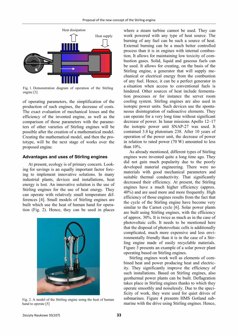
ferences [4]. Small models of Stirling engines are
built which use the heat of human hand for opera-
tion (Fig. 2). Hence, they can be used in places
where a steam turbine cannot be used. They can
work powered with any type of heat source. The
burning of any fuel can be such a source of heat.
External burning can be a much better controlled
process than it is in engines with internal combus-
tion. It allows for maintaining low toxicity of com-
bustion gases. Solid, liquid and gaseous fuels can
be used. It allows for creating, on the basis of the
Stirling engine, a generator that will supply me-
chanical or electrical energy from the combustion
of any fuel. Hence, it can be a perfect generator in
a situation when access to conventional fuels is
hindered. Other sources of heat include fermenta-
tion processes or for instance the server room
cooling system. Stirling engines are also used in
isotopic power units. Such devices use the sponta-
neous disintegration of radioactive elements. They
can operate for a very long time without significant
decrease of power. In lunar missions Apollo 12–17
the isotopic power unit SNAP-27 was used. It
contained 3.8 kg plutonium 238. After 10 years of
operation of the power unit, the decrease of power
in relation to rated power (70 W) amounted to less
than 10%.
As already mentioned, different types of Stirling
engines were invented quite a long time ago. They
did not gain much popularity due to the poorly
developed material engineering. There were no
materials with good mechanical parameters and
suitable thermal conductivity. That significantly
decreased their efficiency. At present, the Stirling
engines have a much higher efficiency (approx.
40%) and are used more and more frequently. High
efficiency of those engines results from the fact that
the cycle of the Stirling engine have become very
similar to the Carnot cycle [6]. Solar power plants
are built using Stirling engines, with the efficiency
of approx. 30%. It is twice as much as in the case of
photovoltaic cells. It needs to be mentioned here
that the disposal of photovoltaic cells is additionally
complicated, much more expensive and less envi-
ronmentally friendly than it is in the case of a Stir-
ling engine made of easily recyclable materials.
Figure 3 presents an example of a solar power plant
operating based on Stirling engines.
Stirling engines work well as elements of com-
bined heat and power producing heat and electric-
ity. They significantly improve the efficiency of
such installations. Based on Stirling engines, also
geothermal power plants can be built. Deflagration
takes place in Stirling engines thanks to which they
operate smoothly and noiselessly. Due to the speci-
ficity of work, they were used for quiet drives of
submarines. Figure 4 presents HMS Gotland sub-
marine with the drive using Stirling engines. Hence,
Heat supply
Heat dissipation
Fig. 1. Demonstration diagram of operation of the Stirling
engine [3]
Fig. 2. A model of the Stirling engine using the heat of human
hand to operate [5]
Marek Jaśkiewicz, Wojciech Sadkowski, Mateusz Marciniewski, Krzysztof Olejnik, Józef Stokłosa
34 Scientific Journals 35(107)
they can be used in places where a steam turbine
cannot be used. They can work powered with any
type of heat source. The burning of any type of fuel
can be such a source of heat. Such external burning
can be a much better controlled process than it is
in engines with internal combustion. It allows
for maintaining low toxicity of combustion gases.
Solid, liquid and gaseous fuels can be used. It
allows for creating, on the basis of the Stirling
engine, a generator that will supply mechanical
or electrical energy from the combustion of any
fuel [7].
In all mentioned uses the proposed engine can
be used. The engine can be used in high, as well as
in low power systems. In high power systems the
engine needs to have suitably large dimensions.
Discussion on structure and the principle of operation of the proposed engine
The cycle of operation of the proposed engine
consists of two stages: heating and cooling. During
the heating stage, the working gas is heated as
a result of what its volume is expanded and the
piston is pushed out. In the final phase of pushing
out the piston, the displacer rotates by 180 degrees,
and then the cooling stage occurs. Cooling of the
working gas causes the decrease of its volume and
the moving back of the piston. In the final phase of
the moving back of the piston, the displacer rotates
by 180 degrees and the heating stage occurs again.
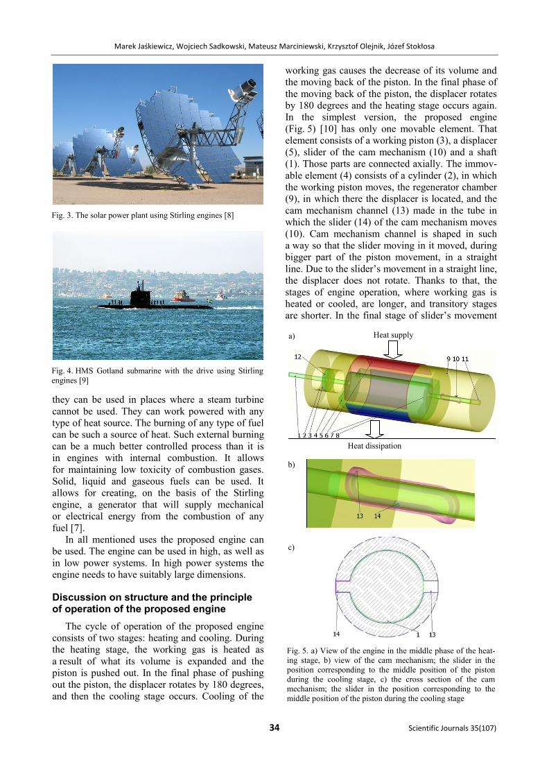
In the simplest version, the proposed engine
(Fig. 5) [10] has only one movable element. That
element consists of a working piston (3), a displacer
(5), slider of the cam mechanism (10) and a shaft
(1). Those parts are connected axially. The immov-
able element (4) consists of a cylinder (2), in which
the working piston moves, the regenerator chamber
(9), in which there the displacer is located, and the
cam mechanism channel (13) made in the tube in
which the slider (14) of the cam mechanism moves
(10). Cam mechanism channel is shaped in such
a way so that the slider moving in it moved, during
bigger part of the piston movement, in a straight
line. Due to the slider’s movement in a straight line,
the displacer does not rotate. Thanks to that, the
stages of engine operation, where working gas is
heated or cooled, are longer, and transitory stages
are shorter. In the final stage of slider’s movement
Fig. 3. The solar power plant using Stirling engines [8]
Fig. 4. HMS Gotland submarine with the drive using Stirling
engines [9]
Heat supply
Heat dissipation
Fig. 5. a) View of the engine in the middle phase of the heat-
ing stage, b) view of the cam mechanism; the slider in the
position corresponding to the middle position of the piston
during the cooling stage, c) the cross section of the cam
mechanism; the slider in the position corresponding to the
middle position of the piston during the cooling stage
a)
b)
c)
Proposal of the new concept of the Stirling engine
Zeszyty Naukowe 35(107) 35
in the cam mechanism channel, the displacer rotates
by 180 degrees and the engines proceeds to the next
stage of operation. Figure 5 presents the view of the
engine with numbered elements in the middle phase
of the cooling stage. The displacer covers the
cooled part of the regenerator (7), the gas inside the
engine is heated and expanded causing the pulling
out of the piston.
Description of elements (Fig. 5): 1 – engine
shaft, 2 – cylinder, 3 – piston, 4 – engine immov-
able element, 5 – displacer, 6 – heated part of the
regenerator, 7 – cooled part of the regenerator 8 –
balancing element, 9 – regenerator chamber, 10 –
cam mechanism, 11 – tube, 12 – O-ring, 13 – cam
mechanism channel, 14 – slider. During the heating
stage, the displacer completely covers the cooled
part during the bigger part of pulling out of the
piston when due to the operation of the cam
mechanism the shaft is set into rotary movement
and rotates by 180 degrees. This causes the rotation
of the displacer and the passing to the cooling
stage. Figure 6 presents the view of the engine dur-
ing the movement of rotation through the shaft with
the displacer. The piston is pulled out as much as
possible.
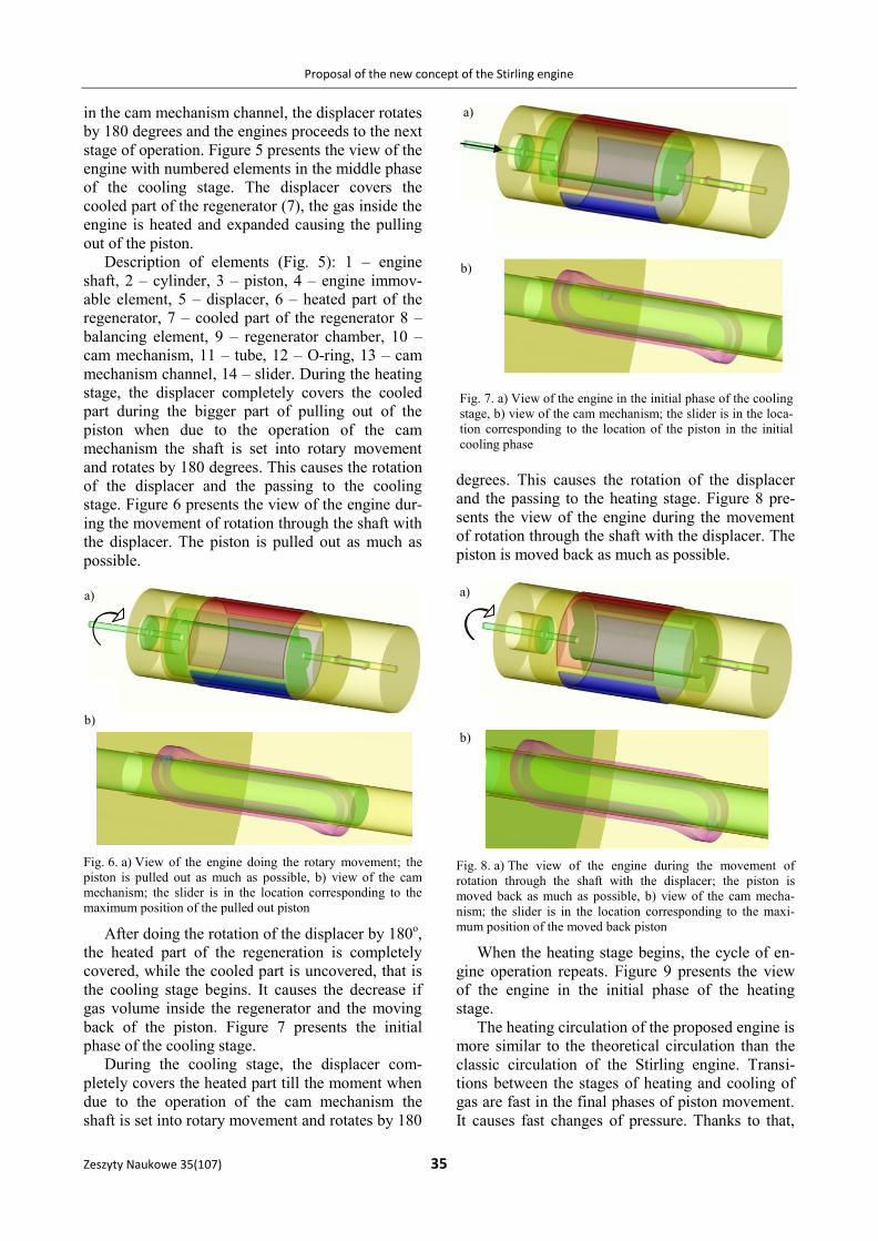
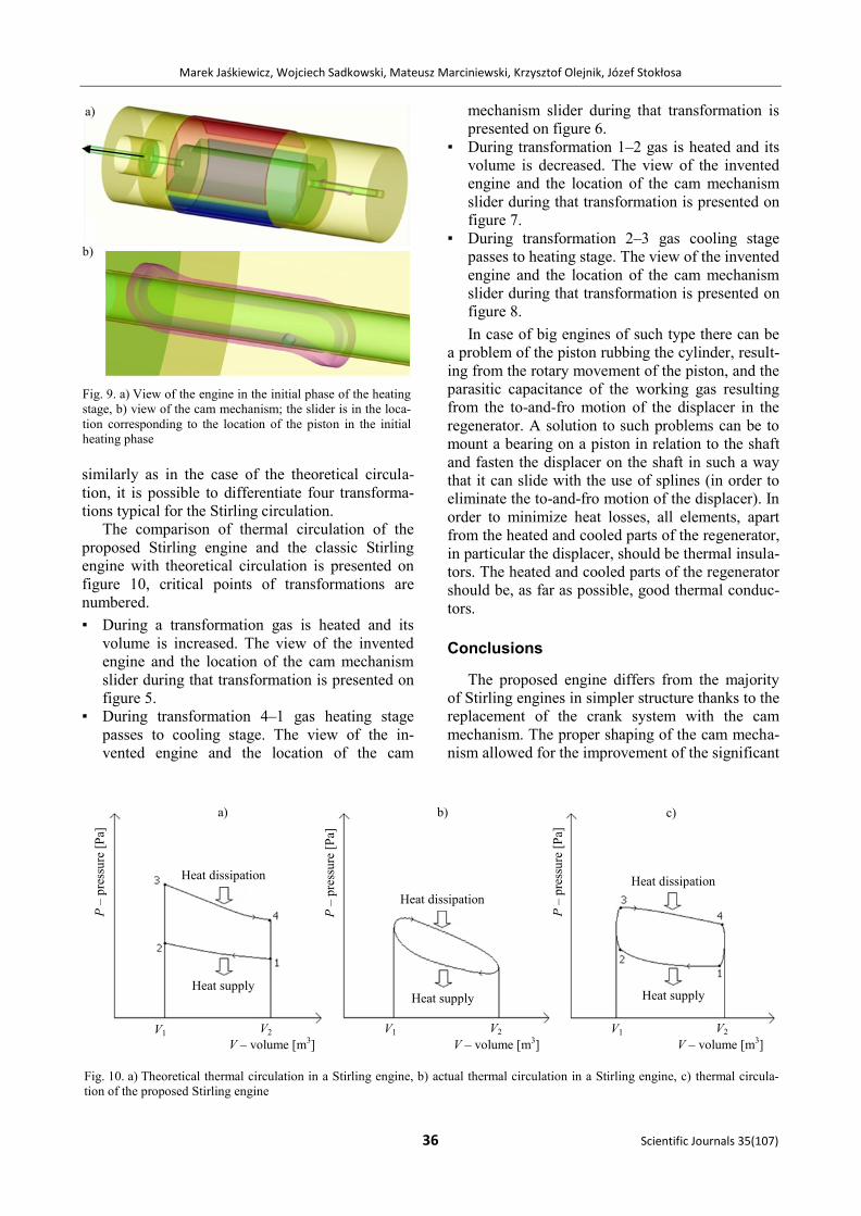
Fig. 6. a) View of the engine doing the rotary movement; the
piston is pulled out as much as possible, b) view of the cam
mechanism; the slider is in the location corresponding to the
maximum position of the pulled out piston
After doing the rotation of the displacer by 180o,
the heated part of the regeneration is completely
covered, while the cooled part is uncovered, that is
the cooling stage begins. It causes the decrease if
gas volume inside the regenerator and the moving
back of the piston. Figure 7 presents the initial
phase of the cooling stage.
During the cooling stage, the displacer com-
pletely covers the heated part till the moment when
due to the operation of the cam mechanism the
shaft is set into rotary movement and rotates by 180
degrees. This causes the rotation of the displacer
and the passing to the heating stage. Figure 8 pre-
sents the view of the engine during the movement
of rotation through the shaft with the displacer. The
piston is moved back as much as possible.
Fig. 8. a) The view of the engine during the movement of
rotation through the shaft with the displacer; the piston is
moved back as much as possible, b) view of the cam mecha-
nism; the slider is in the location corresponding to the maxi-
mum position of the moved back piston
When the heating stage begins, the cycle of en-
gine operation repeats. Figure 9 presents the view
of the engine in the initial phase of the heating
stage.
The heating circulation of the proposed engine is
more similar to the theoretical circulation than the
classic circulation of the Stirling engine. Transi-
tions between the stages of heating and cooling of
gas are fast in the final phases of piston movement.
It causes fast changes of pressure. Thanks to that,
a)
b)
Fig. 7. a) View of the engine in the initial phase of the cooling
stage, b) view of the cam mechanism; the slider is in the loca-
tion corresponding to the location of the piston in the initial
cooling phase
a)
b)
a)
b)
Marek Jaśkiewicz, Wojciech Sadkowski, Mateusz Marciniewski, Krzysztof Olejnik, Józef Stokłosa
36 Scientific Journals 35(107)
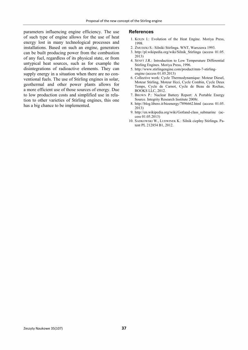
similarly as in the case of the theoretical circula-
tion, it is possible to differentiate four transforma-
tions typical for the Stirling circulation.
The comparison of thermal circulation of the
proposed Stirling engine and the classic Stirling
engine with theoretical circulation is presented on
figure 10, critical points of transformations are
numbered.
▪ During a transformation gas is heated and its
volume is increased. The view of the invented
engine and the location of the cam mechanism
slider during that transformation is presented on
figure 5.
▪ During transformation 4–1 gas heating stage
passes to cooling stage. The view of the in-
vented engine and the location of the cam
mechanism slider during that transformation is
presented on figure 6.
▪ During transformation 1–2 gas is heated and its
volume is decreased. The view of the invented
engine and the location of the cam mechanism
slider during that transformation is presented on
figure 7.
▪ During transformation 2–3 gas cooling stage
passes to heating stage. The view of the invented
engine and the location of the cam mechanism
slider during that transformation is presented on
figure 8.
In case of big engines of such type there can be
a problem of the piston rubbing the cylinder, result-
ing from the rotary movement of the piston, and the
parasitic capacitance of the working gas resulting
from the to-and-fro motion of the displacer in the
regenerator. A solution to such problems can be to
mount a bearing on a piston in relation to the shaft
and fasten the displacer on the shaft in such a way
that it can slide with the use of splines (in order to
eliminate the to-and-fro motion of the displacer). In
order to minimize heat losses, all elements, apart
from the heated and cooled parts of the regenerator,
in particular the displacer, should be thermal insula-
tors. The heated and cooled parts of the regenerator
should be, as far as possible, good thermal conduc-
tors.
Conclusions
The proposed engine differs from the majority
of Stirling engines in simpler structure thanks to the
replacement of the crank system with the cam
mechanism. The proper shaping of the cam mecha-
nism allowed for the improvement of the significant
a)
b)
Fig. 9. a) View of the engine in the initial phase of the heating
stage, b) view of the cam mechanism; the slider is in the loca-
tion corresponding to the location of the piston in the initial
heating phase
Fig. 10. a) Theoretical thermal circulation in a Stirling engine, b) actual thermal circulation in a Stirling engine, c) thermal circula-
tion of the proposed Stirling engine
b) a) c)
P –
pre
ssu
re [
Pa]
P –
pre
ssu
re [
Pa]
P –
pre
ssu
re [
Pa]
V – volume [m3] V – volume [m3] V – volume [m3]
Heat dissipation
Heat dissipation
Heat dissipation
Heat supply Heat supply Heat supply
V1 V2 V1 V2 V2 V1
Proposal of the new concept of the Stirling engine
Zeszyty Naukowe 35(107) 37
parameters influencing engine efficiency. The use
of such type of engine allows for the use of heat
energy lost in many technological processes and
installations. Based on such an engine, generators
can be built producing power from the combustion
of any fuel, regardless of its physical state, or from
untypical heat sources, such as for example the
disintegrations of radioactive elements. They can
supply energy in a situation when there are no con-
ventional fuels. The use of Stirling engines in solar,
geothermal and other power plants allows for
a more efficient use of those sources of energy. Due
to low production costs and simplified use in rela-
tion to other varieties of Stirling engines, this one
has a big chance to be implemented.
References
1. KOLIN I.: Evolution of the Heat Engine. Moriya Press,
1998.
2. ŻMUDZKI S.: Silniki Stirlinga. WNT, Warszawa 1993.
3. http://pl.wikipedia.org/wiki/Silnik_Stirlinga (access 01.05.
2013)
4. SENFT J.R.: Introduction to Low Temperature Differential
Stirling Engines. Moriya Press, 1996.
5. http://www.stirlingengine.com/product/mm-7-stirling-
engine (access 01.05.2013)
6. Collective work: Cycle Thermodynamique: Moteur Diesel,
Moteur Stirling, Moteur Hcci, Cycle Combin, Cycle Deux
Temps, Cycle de Carnot, Cycle de Beau de Rochas,
BOOKS LLC, 2012.
7. BROWN P.: Nuclear Battery Report: A Portable Energy
Source. Integrity Research Institute 2008r.
8. http://blog.libero.it/bioenergy/7896662.html (access 01.05.
2013)
9. http://en.wikipedia.org/wiki/Gotland-class_submarine (ac-
cess 01.05.2013)
10. SADKOWSKI W., LUDWINEK K.: Silnik cieplny Stirlinga. Pa-
tent PL 212854 B1, 2012.