THE DEPENDENCE OF THE INRUSH CURRENT OF A … IMEKO World Congress Fundamental and Applied Metrology...
4
XIX IMEKO World Congress Fundamental and Applied Metrology September 6−11, 2009, Lisbon, Portugal THE DEPENDENCE OF THE INRUSH CURRENT OF A TRANSFORMER UPON SWITCHING OFF/ON PHASES Andrzej Dobrogowski 1 , Przemyslaw Lisowski 2 1 Poznan University of Technology, Poznan, Poland, [email protected] 2 Poznan University of Technology, Poznan, Poland, [email protected] Abstract − The relation between the level of the inrush current of a single phase transformer and the phases of disconnecting the transformer from AC source and then connecting it to the same source is investigated. The measurement setup is presented. Results of the experiment are discussed. Keywords: inrush current, switching off/on, saturation. 1. INTRODUCTION The transient magnetizing current of a transformer flowing after connecting the transformer with AC source is called the inrush current [1, 2]. The inrush current is highly asymmetric. It results from saturation of a core of the transformer caused by excessive growth of a magnetic flux in one direction only. The first peak of an inrush current may exceed many times the value of a transformer’s nominal current [3]. Therefore the obvious goal is to limit the level and the duration of the inrush current [2-7]. The level of the inrush current depends on the design of a transformer and its circuit. It also depends on the instant (the phase of a source’s voltage) the transformer is switched on [4, 7], as well as the value of the remanence flux just before switching on. This paper deals with the relation between the level of the inrush current and the phases of disconnecting a single- phase transformer from AC source and then connecting it to the same source. This relation is recognized in the literature of the subject [1], but – to the authors’ best knowledge – not to the extent presented in this paper. Since the inrush current might be seriously disturbing (sometimes even devastating) phenomenon its extreme value should be assessed for a given transformer. As an indicator of the inrush current’s level serves the magnitude of its first peak. Thus for some transformer the investigated relation was measured using some specially designed apparatus of the measuring set. Then the procedure of calculation of the inrush current was developed. To this goal the remanence flux of the examined transformer’s core in a function of switching off phase of a 230 V AC voltage was determined. A mathematical model of the magnetizing characteristics of the examined transformer within the magnetic flux range widely enough has been established. Exploiting that knowledge and the well known relation between the voltage and the flux the magnitude of first peak of the inrush current for a set of pairs of switching off – switching on phases of the transformer was computed. 2. CIRCUITRY OF THE EXPERIMENT The 1000 VA transformer used in some uninterruptible power supply (UPS) unit has been examined. The measurement setup is shown in Fig. 1. A 230 V AC source is connected to the transformer examined (4) throughout PowerOff-2 (2) and DIIP-1 (3) units. PowerOff-2 enables switching off and on of the transformer at the predetermined phase. In the paper the phase is given in time unit within the period of AC source voltage. DIIP-1 provides necessary galvanic isolation between circuits. Oscilloscope measures the samples of current and voltage of the transformer’s primary winding. The measurement process is supported by PC, not shown in the Fig. 1. It is assumed that the time interval between switching off and switching on of the transformer is long enough for transient to vanish. In order to reach this goal the time elapsing between switching off instant and switching on one of a transformer encompasses some number of periods of AC source. Fig. 1. The measurement setup. 3. RESULTS OF MEASUREMENT Table 1 contains the measured values of the magnitude of the first peak of the inrush current of the transformer examined as function of switching off phase (the phase of disconnection of the transformer) and the phase difference to the next switching on (connection) of the transformer. The phase zero denotes an instant of negative-to-positive zero crossing of AC transformer’s supplying voltage (obviously the phase 10 ms corresponds to positive-to-negative zero crossing of the AC source voltage). The phase difference is
Transcript of THE DEPENDENCE OF THE INRUSH CURRENT OF A … IMEKO World Congress Fundamental and Applied Metrology...
XIX IMEKO World Congress Fundamental and Applied Metrology
September 6−11, 2009, Lisbon, Portugal
THE DEPENDENCE OF THE INRUSH CURRENT OF A TRANSFORMER UPON SWITCHING OFF/ON PHASES
Andrzej Dobrogowski 1, Przemyslaw Lisowski 2
1 Poznan University of Technology, Poznan, Poland, [email protected]
2 Poznan University of Technology, Poznan, Poland, [email protected] Abstract − The relation between the level of the inrush
current of a single phase transformer and the phases of disconnecting the transformer from AC source and then connecting it to the same source is investigated. The measurement setup is presented. Results of the experiment are discussed.
Keywords: inrush current, switching off/on, saturation.
1. INTRODUCTION
The transient magnetizing current of a transformer flowing after connecting the transformer with AC source is called the inrush current [1, 2]. The inrush current is highly asymmetric. It results from saturation of a core of the transformer caused by excessive growth of a magnetic flux in one direction only. The first peak of an inrush current may exceed many times the value of a transformer’s nominal current [3]. Therefore the obvious goal is to limit the level and the duration of the inrush current [2-7]. The level of the inrush current depends on the design of a transformer and its circuit. It also depends on the instant (the phase of a source’s voltage) the transformer is switched on [4, 7], as well as the value of the remanence flux just before switching on.
This paper deals with the relation between the level of the inrush current and the phases of disconnecting a single-phase transformer from AC source and then connecting it to the same source. This relation is recognized in the literature of the subject [1], but – to the authors’ best knowledge – not to the extent presented in this paper. Since the inrush current might be seriously disturbing (sometimes even devastating) phenomenon its extreme value should be assessed for a given transformer. As an indicator of the inrush current’s level serves the magnitude of its first peak. Thus for some transformer the investigated relation was measured using some specially designed apparatus of the measuring set. Then the procedure of calculation of the inrush current was developed. To this goal the remanence flux of the examined transformer’s core in a function of switching off phase of a 230 V AC voltage was determined. A mathematical model of the magnetizing characteristics of the examined transformer within the magnetic flux range widely enough has been established. Exploiting that knowledge and the well known relation between the voltage and the flux the magnitude of first peak of the inrush current for a set of
pairs of switching off – switching on phases of the transformer was computed.
2. CIRCUITRY OF THE EXPERIMENT
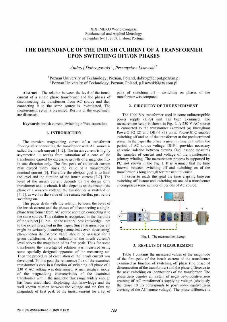
The 1000 VA transformer used in some uninterruptible power supply (UPS) unit has been examined. The measurement setup is shown in Fig. 1. A 230 V AC source is connected to the transformer examined (4) throughout PowerOff-2 (2) and DIIP-1 (3) units. PowerOff-2 enables switching off and on of the transformer at the predetermined phase. In the paper the phase is given in time unit within the period of AC source voltage. DIIP-1 provides necessary galvanic isolation between circuits. Oscilloscope measures the samples of current and voltage of the transformer’s primary winding. The measurement process is supported by PC, not shown in the Fig. 1. It is assumed that the time interval between switching off and switching on of the transformer is long enough for transient to vanish.
In order to reach this goal the time elapsing between switching off instant and switching on one of a transformer encompasses some number of periods of AC source.
Fig. 1. The measurement setup.
3. RESULTS OF MEASUREMENT
Table 1 contains the measured values of the magnitude of the first peak of the inrush current of the transformer examined as function of switching off phase (the phase of disconnection of the transformer) and the phase difference to the next switching on (connection) of the transformer. The phase zero denotes an instant of negative-to-positive zero crossing of AC transformer’s supplying voltage (obviously the phase 10 ms corresponds to positive-to-negative zero crossing of the AC source voltage). The phase difference is
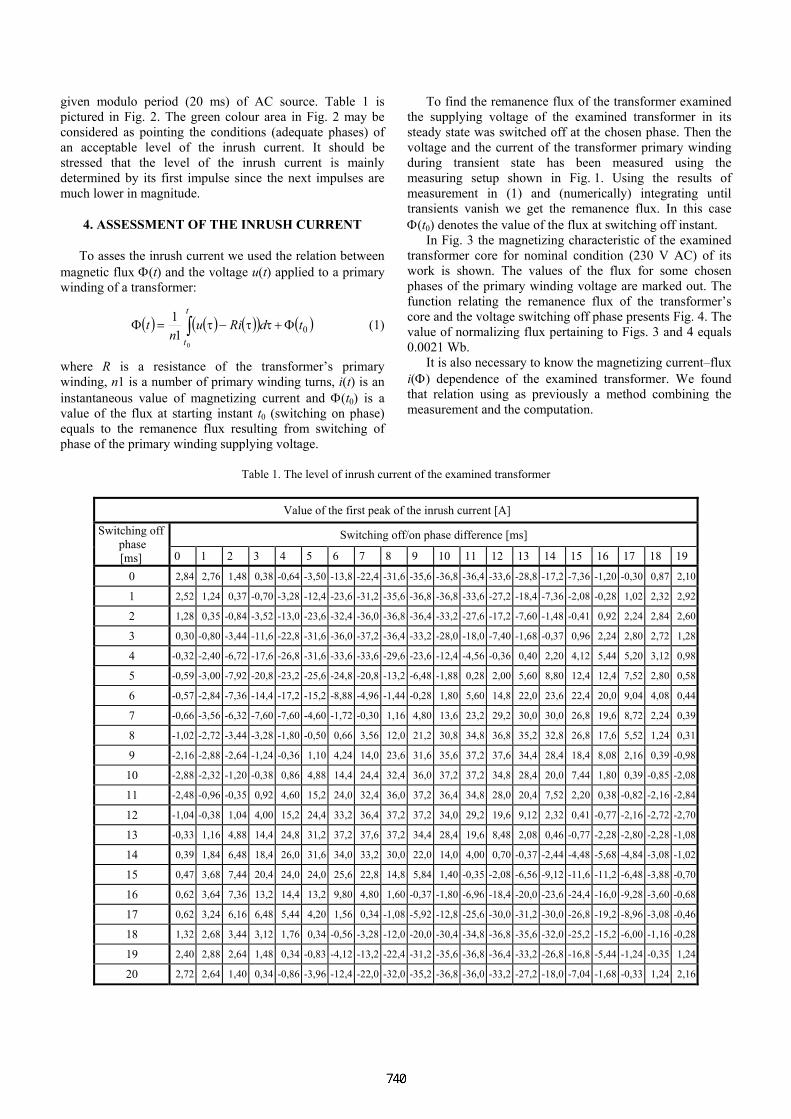
given modulo period (20 ms) of AC source. Table 1 is pictured in Fig. 2. The green colour area in Fig. 2 may be considered as pointing the conditions (adequate phases) of an acceptable level of the inrush current. It should be stressed that the level of the inrush current is mainly determined by its first impulse since the next impulses are much lower in magnitude.
4. ASSESSMENT OF THE INRUSH CURRENT
To asses the inrush current we used the relation between magnetic flux Φ(t) and the voltage u(t) applied to a primary winding of a transformer:
( ) ( ) ( )( ) ( )00
11 tdRiun
tt
t
Φ+ττ−τ=Φ ∫ (1)
where R is a resistance of the transformer’s primary winding, n1 is a number of primary winding turns, i(t) is an instantaneous value of magnetizing current and Φ(t0) is a value of the flux at starting instant t0 (switching on phase) equals to the remanence flux resulting from switching of phase of the primary winding supplying voltage.
To find the remanence flux of the transformer examined the supplying voltage of the examined transformer in its steady state was switched off at the chosen phase. Then the voltage and the current of the transformer primary winding during transient state has been measured using the measuring setup shown in Fig. 1. Using the results of measurement in (1) and (numerically) integrating until transients vanish we get the remanence flux. In this case Φ(t0) denotes the value of the flux at switching off instant.
In Fig. 3 the magnetizing characteristic of the examined transformer core for nominal condition (230 V AC) of its work is shown. The values of the flux for some chosen phases of the primary winding voltage are marked out. The function relating the remanence flux of the transformer’s core and the voltage switching off phase presents Fig. 4. The value of normalizing flux pertaining to Figs. 3 and 4 equals 0.0021 Wb.
It is also necessary to know the magnetizing current–flux i(Φ) dependence of the examined transformer. We found that relation using as previously a method combining the measurement and the computation.
Table 1. The level of inrush current of the examined transformer
Value of the first peak of the inrush current [A]
Switching off/on phase difference [ms] Switching off phase [ms] 0 1 2 3 4 5 6 7 8 9 10 11 12 13 14 15 16 17 18 19
0 2,84 2,76 1,48 0,38 -0,64 -3,50 -13,8 -22,4 -31,6 -35,6 -36,8 -36,4 -33,6 -28,8 -17,2 -7,36 -1,20 -0,30 0,87 2,10
1 2,52 1,24 0,37 -0,70 -3,28 -12,4 -23,6 -31,2 -35,6 -36,8 -36,8 -33,6 -27,2 -18,4 -7,36 -2,08 -0,28 1,02 2,32 2,92
2 1,28 0,35 -0,84 -3,52 -13,0 -23,6 -32,4 -36,0 -36,8 -36,4 -33,2 -27,6 -17,2 -7,60 -1,48 -0,41 0,92 2,24 2,84 2,60
3 0,30 -0,80 -3,44 -11,6 -22,8 -31,6 -36,0 -37,2 -36,4 -33,2 -28,0 -18,0 -7,40 -1,68 -0,37 0,96 2,24 2,80 2,72 1,28
4 -0,32 -2,40 -6,72 -17,6 -26,8 -31,6 -33,6 -33,6 -29,6 -23,6 -12,4 -4,56 -0,36 0,40 2,20 4,12 5,44 5,20 3,12 0,98
5 -0,59 -3,00 -7,92 -20,8 -23,2 -25,6 -24,8 -20,8 -13,2 -6,48 -1,88 0,28 2,00 5,60 8,80 12,4 12,4 7,52 2,80 0,58
6 -0,57 -2,84 -7,36 -14,4 -17,2 -15,2 -8,88 -4,96 -1,44 -0,28 1,80 5,60 14,8 22,0 23,6 22,4 20,0 9,04 4,08 0,44
7 -0,66 -3,56 -6,32 -7,60 -7,60 -4,60 -1,72 -0,30 1,16 4,80 13,6 23,2 29,2 30,0 30,0 26,8 19,6 8,72 2,24 0,39
8 -1,02 -2,72 -3,44 -3,28 -1,80 -0,50 0,66 3,56 12,0 21,2 30,8 34,8 36,8 35,2 32,8 26,8 17,6 5,52 1,24 0,31
9 -2,16 -2,88 -2,64 -1,24 -0,36 1,10 4,24 14,0 23,6 31,6 35,6 37,2 37,6 34,4 28,4 18,4 8,08 2,16 0,39 -0,98
10 -2,88 -2,32 -1,20 -0,38 0,86 4,88 14,4 24,4 32,4 36,0 37,2 37,2 34,8 28,4 20,0 7,44 1,80 0,39 -0,85 -2,08
11 -2,48 -0,96 -0,35 0,92 4,60 15,2 24,0 32,4 36,0 37,2 36,4 34,8 28,0 20,4 7,52 2,20 0,38 -0,82 -2,16 -2,84
12 -1,04 -0,38 1,04 4,00 15,2 24,4 33,2 36,4 37,2 37,2 34,0 29,2 19,6 9,12 2,32 0,41 -0,77 -2,16 -2,72 -2,70
13 -0,33 1,16 4,88 14,4 24,8 31,2 37,2 37,6 37,2 34,4 28,4 19,6 8,48 2,08 0,46 -0,77 -2,28 -2,80 -2,28 -1,08
14 0,39 1,84 6,48 18,4 26,0 31,6 34,0 33,2 30,0 22,0 14,0 4,00 0,70 -0,37 -2,44 -4,48 -5,68 -4,84 -3,08 -1,02
15 0,47 3,68 7,44 20,4 24,0 24,0 25,6 22,8 14,8 5,84 1,40 -0,35 -2,08 -6,56 -9,12 -11,6 -11,2 -6,48 -3,88 -0,70
16 0,62 3,64 7,36 13,2 14,4 13,2 9,80 4,80 1,60 -0,37 -1,80 -6,96 -18,4 -20,0 -23,6 -24,4 -16,0 -9,28 -3,60 -0,68
17 0,62 3,24 6,16 6,48 5,44 4,20 1,56 0,34 -1,08 -5,92 -12,8 -25,6 -30,0 -31,2 -30,0 -26,8 -19,2 -8,96 -3,08 -0,46
18 1,32 2,68 3,44 3,12 1,76 0,34 -0,56 -3,28 -12,0 -20,0 -30,4 -34,8 -36,8 -35,6 -32,0 -25,2 -15,2 -6,00 -1,16 -0,28
19 2,40 2,88 2,64 1,48 0,34 -0,83 -4,12 -13,2 -22,4 -31,2 -35,6 -36,8 -36,4 -33,2 -26,8 -16,8 -5,44 -1,24 -0,35 1,24
20 2,72 2,64 1,40 0,34 -0,86 -3,96 -12,4 -22,0 -32,0 -35,2 -36,8 -36,0 -33,2 -27,2 -18,0 -7,04 -1,68 -0,33 1,24 2,16
Fig. 2. The picture of Table 1.
Fig. 3. Magnetizing characteristic of the transformer’s core.
Fig. 4. The remanence flux of the transformer’s core as a function of switching off phase.
We interrupt the primary winding supplying voltage at a chosen phase and after some time (enough for transients to vanish) we switch on the supplying voltage again. Using the setup from Fig. 1 we measured the inrush current and using (1) we found the course of the flux. We repeated this procedure for different phases of switching off action. The time of voltage break was the same in every case. The magnitude of first peak of the inrush current and corresponding value of the flux pointed out consecutive points of the needed characteristic i(Φ). After least squares matching we modelled i(Φ) characteristic using an expression:
( )
>Φ≥Φ≥=Φ<Φ≤−
−<Φ
−Φ
−+Φ
=ΦΦ
Φ−
0034.000034.0000034.0
0034.0
81.122388820006.0
00006.0
81.12238882
2.2852
2.2852
e
ei (2)
The expression (2) features discontinuity at the vicinity of beginning of coordinate system. In our consideration this discontinuity is without consequences. We are allowed not to take into account the hysteresis loop, as in examined transformer its width is approx. 60 mA, and the values of magnitude of inrush current are much bigger. The i(Φ) characteristic is shown in Fig. 5.
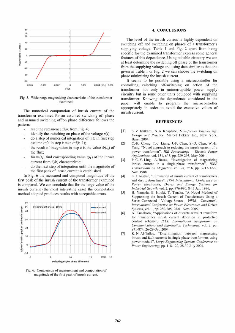
Fig. 5. Wide range magnetizing characteristic of the transformer examined.
The numerical computation of inrush current of the transformer examined for an assumed switching off phase and assumed switching off/on phase difference follows the pattern:
- read the remanence flux from Fig. 4; - identify the switching on phase of the voltage u(t); - do a step of numerical integration of (1); in first step
assume i=0, in step k take i=i(k–1); - the result of integration in step k is the value Φ(tk) of
the flux; - for Φ(tk) find corresponding value i(tk) of the inrush
current from i(Φ) characteristic; - do the next step of integration until the magnitude of
the first peak of inrush current is established. In Fig. 6 the measured and computed magnitude of the
first peak of the inrush current of the transformer examined is compared. We can conclude that for the large value of the inrush current (the most interesting case) the computation method adopted produces results with acceptable errors.
Fig. 6. Comparison of measurement and computation of magnitude of the first peak of inrush current.
4. CONCLUSIONS
The level of the inrush current is highly dependent on switching off and switching on phases of a transformer’s supplying voltage. Table 1 and Fig. 2 apart from being specific for the examined transformer express some general features of this dependence. Using suitable circuitry we can at least determine the switching off phase of the transformer from the supplying voltage and using data similar to that one given in Table 1 or Fig. 2 we can choose the switching on phase minimizing the inrush current.
It seems to be possible using a microcontroller for controlling switching off/switching on action of the transformer not only in uninterruptible power supply circuitry but in some other units equipped with supplying transformer. Knowing the dependence considered in the paper will enable to program the microcontroller appropriately in order to avoid the excessive values of inrush current.
REFERENCES
[1] S. V. Kulkarni, S. A. Khaparde, Transformer Engineering. Design and Practice, Marcel Dekker Inc., New York, Basel, 2004.
[2] C.-K. Cheng, T.-J. Liang, J.-F. Chen, S.-D. Chen, W.-H. Yang, “Novel approach to reducing the inrush current of a power transformer”, IEE Proceedings – Electric Power Applications, vol. 151, nº 3, pp. 289-295, May 2004.
[3] P. C. Y. Ling, A. Basak, “Investigation of magnetizing inrush current in a single-phase transformer”, IEEE Transactions on Magnetics, vol. 24, nº 6, pp. 3217-3222, Nov. 1988.
[4] S. J. Asghar, “Elimination of inrush current of transformers and distribution lines”, 1996 International Conference on Power Electronics, Drives and Energy Systems for Industrial Growth, vol. 2, pp. 976-980, 8-11 Jan. 1996.
[5] H. Yamada, E. Hiraki, T. Tanaka, “A Novel Method of Suppressing the Inrush Current of Transformers Using a Series-Connected Voltage-Source PWM Converter”, International Conference on Power Electronics and Drives Systems, vol. 1, pp. 280-285, 28-01 Nov. 2005.
[6] A. Kunakorn, “Applications of discrete wavelet transform for transformer inrush current detection in protective control scheme”, IEEE International Symposium on Communications and Information Technology, vol. 2, pp. 871-874, 26-29 Oct. 2004.
[7] K. N. Al-Tallaq, “Discrimination between magnetizing inrush and fault currents in single-phase transformers using power method”, Large Engineering Systems Conference on Power Engineering, pp. 118-122, 28-30 July 2004.


![THE EFFECT OF SECONDARY METALWORKING PROCESSES ON … · The general dependence of fracture toughness on yield strength. Based on [4] ... means that for the same crack growth resistance](https://static.fdocuments.pl/doc/165x107/5f672b842d17bd2398498312/the-effect-of-secondary-metalworking-processes-on-the-general-dependence-of-fracture.jpg)