MPEG-1 / MPEG-2 BC Audio - tu-ilmenau.de · Prof. Dr.-Ing. K. Brandenburg, [email protected]...
59
Prof. Dr.-Ing. K. Brandenburg, [email protected] Dr.-Ing. G. Schuller, [email protected] Page 1 MPEG-1 / MPEG-2 BC Audio
Transcript of MPEG-1 / MPEG-2 BC Audio - tu-ilmenau.de · Prof. Dr.-Ing. K. Brandenburg, [email protected]...
Prof. Dr.-Ing. K. Brandenburg, [email protected] Dr.-Ing. G. Schuller, [email protected] Page 1
MPEG-1 / MPEG-2 BC Audio
Prof. Dr.-Ing. K. Brandenburg, [email protected] Dr.-Ing. G. Schuller, [email protected] Page 2
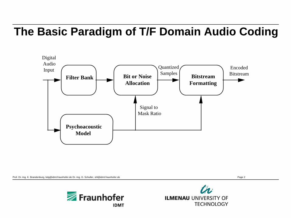
The Basic Paradigm of T/F Domain Audio Coding
Digital Audio Input
Filter Bank
Psychoacoustic Model
Bitstream Formatting
Signal to Mask Ratio
Quantized Samples
Encoded BitstreamBit or Noise
Allocation

Prof. Dr.-Ing. K. Brandenburg, [email protected] Dr.-Ing. G. Schuller, [email protected] Page 3
MPEG Audio Standardization Philosophy (1)• Definition of a complete transmission chain
consists of specification of– Encoding algorithm– Bitstream format– Decoding algorithm
• ITU-T standardizes all three parts ⇒ Encoder output predictable
• MPEG standardizes only bitstream format anddecoder, not the encoder (“informative part”)
ITU-T Approach
MPEG Approach
Prof. Dr.-Ing. K. Brandenburg, [email protected] Dr.-Ing. G. Schuller, [email protected] Page 4
MPEG Audio Standardization Philosophy (2)
• Motivation: open for further improvements, room for specific corporate know-how
• But: No sound quality guaranteed !

Prof. Dr.-Ing. K. Brandenburg, [email protected] Dr.-Ing. G. Schuller, [email protected] Page 5
MPEG-1/2 Audio
• MPEG-1 Audio– Audio coding 32 - 48 kHz, mono/stereo– Layer 1, 2, 3– Layer-3 (aka .mp3) optimized for lower bit-
rates– Copy protection via SCMS included
• MPEG-2 Audio– Low sampling frequencies audio
add 16 - 24 kHz to Layer 1, 2, 3– Multichannel audio, BC
Prof. Dr.-Ing. K. Brandenburg, [email protected] Dr.-Ing. G. Schuller, [email protected] Page 6
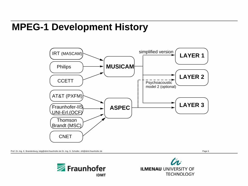
MPEG-1 Development History
IRT (MASCAM)
Philips
CCETT
Thomson Brandt (MSC)
AT&T (PXFM)
Fraunhofer-IIS UNI-Erl.(OCF)
MUSICAM
ASPEC
LAYER 1
LAYER 2
LAYER 3
Psychoacousticmodel 2 (optional)
simplified version
CNET
Prof. Dr.-Ing. K. Brandenburg, [email protected] Dr.-Ing. G. Schuller, [email protected] Page 7
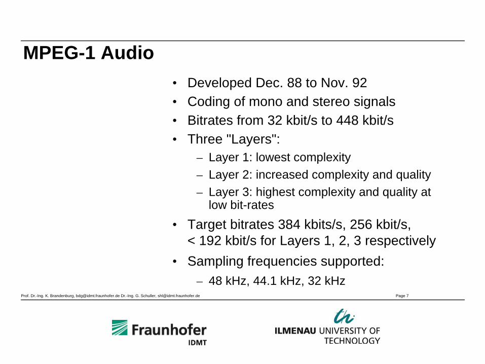
MPEG-1 Audio• Developed Dec. 88 to Nov. 92• Coding of mono and stereo signals• Bitrates from 32 kbit/s to 448 kbit/s• Three "Layers":
– Layer 1: lowest complexity– Layer 2: increased complexity and quality– Layer 3: highest complexity and quality at
low bit-rates• Target bitrates 384 kbits/s, 256 kbit/s,
< 192 kbit/s for Layers 1, 2, 3 respectively• Sampling frequencies supported:
– 48 kHz, 44.1 kHz, 32 kHz
Prof. Dr.-Ing. K. Brandenburg, [email protected] Dr.-Ing. G. Schuller, [email protected] Page 8
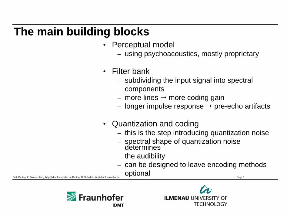
The main building blocks• Perceptual model
– using psychoacoustics, mostly proprietary
• Filter bank– subdividing the input signal into spectral
components– more lines more coding gain– longer impulse response pre-echo artifacts
• Quantization and coding– this is the step introducing quantization noise– spectral shape of quantization noise
determines the audibility
– can be designed to leave encoding methods optional
Prof. Dr.-Ing. K. Brandenburg, [email protected] Dr.-Ing. G. Schuller, [email protected] Page 9
MPEG Audio - Short Description of the Layers (1)
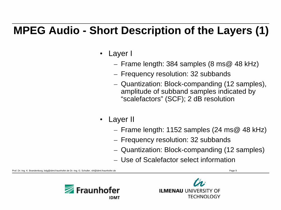
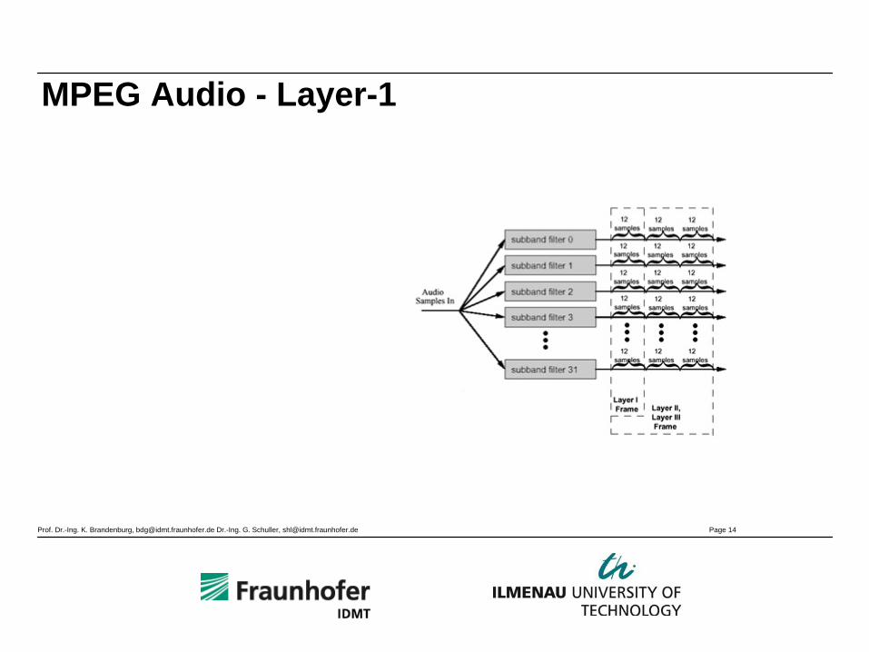
• Layer I– Frame length: 384 samples (8 ms@ 48 kHz)– Frequency resolution: 32 subbands– Quantization: Block-companding (12 samples),
amplitude of subband samples indicated by “scalefactors” (SCF); 2 dB resolution
• Layer II– Frame length: 1152 samples (24 ms@ 48 kHz)– Frequency resolution: 32 subbands– Quantization: Block-companding (12 samples)– Use of Scalefactor select information
Prof. Dr.-Ing. K. Brandenburg, [email protected] Dr.-Ing. G. Schuller, [email protected] Page 10
MPEG Audio - Short Description of the Layers (2)
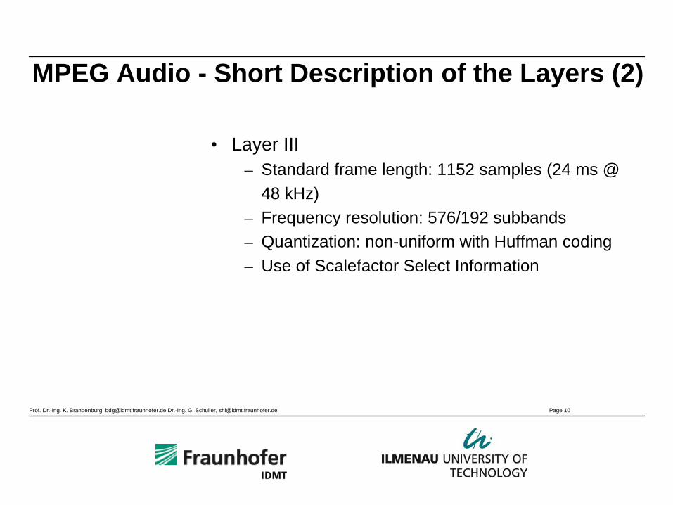
• Layer III– Standard frame length: 1152 samples (24 ms @
48 kHz)– Frequency resolution: 576/192 subbands– Quantization: non-uniform with Huffman coding– Use of Scalefactor Select Information
Prof. Dr.-Ing. K. Brandenburg, [email protected] Dr.-Ing. G. Schuller, [email protected] Page 11
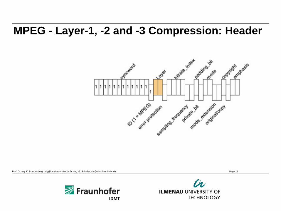
MPEG - Layer-1, -2 and -3 Compression: Header
Prof. Dr.-Ing. K. Brandenburg, [email protected] Dr.-Ing. G. Schuller, [email protected] Page 12
MPEG-1 Layer 1
Prof. Dr.-Ing. K. Brandenburg, [email protected] Dr.-Ing. G. Schuller, [email protected] Page 13
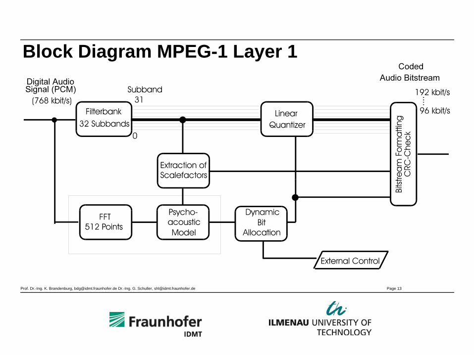
Block Diagram MPEG-1 Layer 1
Prof. Dr.-Ing. K. Brandenburg, [email protected] Dr.-Ing. G. Schuller, [email protected] Page 14
MPEG Audio - Layer-1

Prof. Dr.-Ing. K. Brandenburg, [email protected] Dr.-Ing. G. Schuller, [email protected] Page 15
MPEG Audio - Layer-1 (2)
Prof. Dr.-Ing. K. Brandenburg, [email protected] Dr.-Ing. G. Schuller, [email protected] Page 16
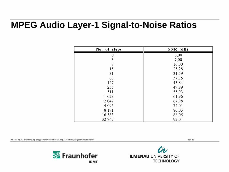
MPEG Audio Layer-1 Signal-to-Noise Ratios
Prof. Dr.-Ing. K. Brandenburg, [email protected] Dr.-Ing. G. Schuller, [email protected] Page 17
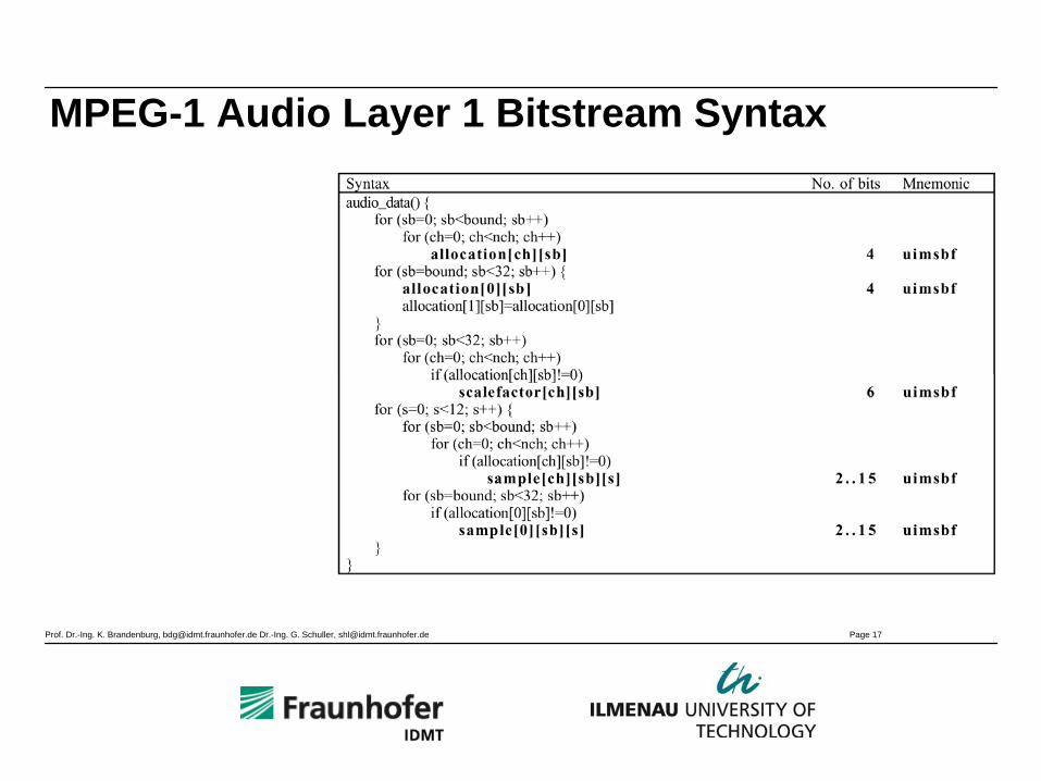
MPEG-1 Audio Layer 1 Bitstream Syntax
Prof. Dr.-Ing. K. Brandenburg, [email protected] Dr.-Ing. G. Schuller, [email protected] Page 18
MPEG-1 Layer 2
Prof. Dr.-Ing. K. Brandenburg, [email protected] Dr.-Ing. G. Schuller, [email protected] Page 19
MPEG Audio - Layer-2 (1)
• Processing of 1152 sample long frames• 32 Sub-bands used; grouping in 3 granules of
12 subband samples• Layer II additionally offers coding of bit
allocation, scalefactors and samples• The number of necessary scalefactors can vary• Use of different windows• Theoretically Minimum of the Coder-/Decoder-
Delays around 35 ms
Prof. Dr.-Ing. K. Brandenburg, [email protected] Dr.-Ing. G. Schuller, [email protected] Page 20
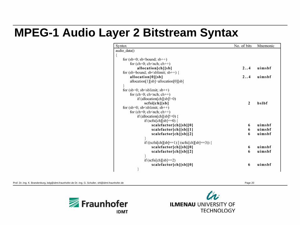
MPEG-1 Audio Layer 2 Bitstream Syntax

Prof. Dr.-Ing. K. Brandenburg, [email protected] Dr.-Ing. G. Schuller, [email protected] Page 21
MPEG-1 Audio Layer 2 Bitstream Syntax (2)

Prof. Dr.-Ing. K. Brandenburg, [email protected] Dr.-Ing. G. Schuller, [email protected] Page 22
MPEG-1 Layer 3

Prof. Dr.-Ing. K. Brandenburg, [email protected] Dr.-Ing. G. Schuller, [email protected] Page 23
MPEG Audio – Layer 3• MP3 is the nickname of the ISO/IEC-Standard
for audio compression described by ISO/IEC IS 11172-3 (MPEG-1 Layer-3) and 13818-3 (MPEG-2 Layer-3)
• The benefits of MP3-formats is that it is a headerless file format, which means that it is not necessary to have the header to play the music
• Allows MP3 streaming• Theoretic minimum delay of the Coder/Decoder
is around 59 ms

Prof. Dr.-Ing. K. Brandenburg, [email protected] Dr.-Ing. G. Schuller, [email protected] Page 24
Block diagram Layer-332 MDCT‘s

Prof. Dr.-Ing. K. Brandenburg, [email protected] Dr.-Ing. G. Schuller, [email protected] Page 25
MPEG Layer-3• Same basic configuration as Layer-2:
– Frame length 24 ms at 48 kHz– Polyphase filter bank
• Specifics of Layer-3:– Hybrid filter bank (32*18 = 576 subbands or
32*6=192 subbands)– nonuniform quantization (implicit noise
shaping) with a power law ( ^.75)
– Huffman coding– Analysis-by-Synthesis structure– Bitreservoir (short time buffer)– Support for variable bitrate (mandatory)

Prof. Dr.-Ing. K. Brandenburg, [email protected] Dr.-Ing. G. Schuller, [email protected] Page 26
Psychoacoustic mode
Block Size
Hybrid Filter bank
MPEG-1 Layer 3
• often used: “Psychoacoustic model 2”
• 1 Frame = 1152 samples = 36 samples per Polyphase filter bank subband
• Additional Modified Discrete Cosine Transform (MDCT), and aliasing reduction stage
Prof. Dr.-Ing. K. Brandenburg, [email protected] Dr.-Ing. G. Schuller, [email protected] Page 27
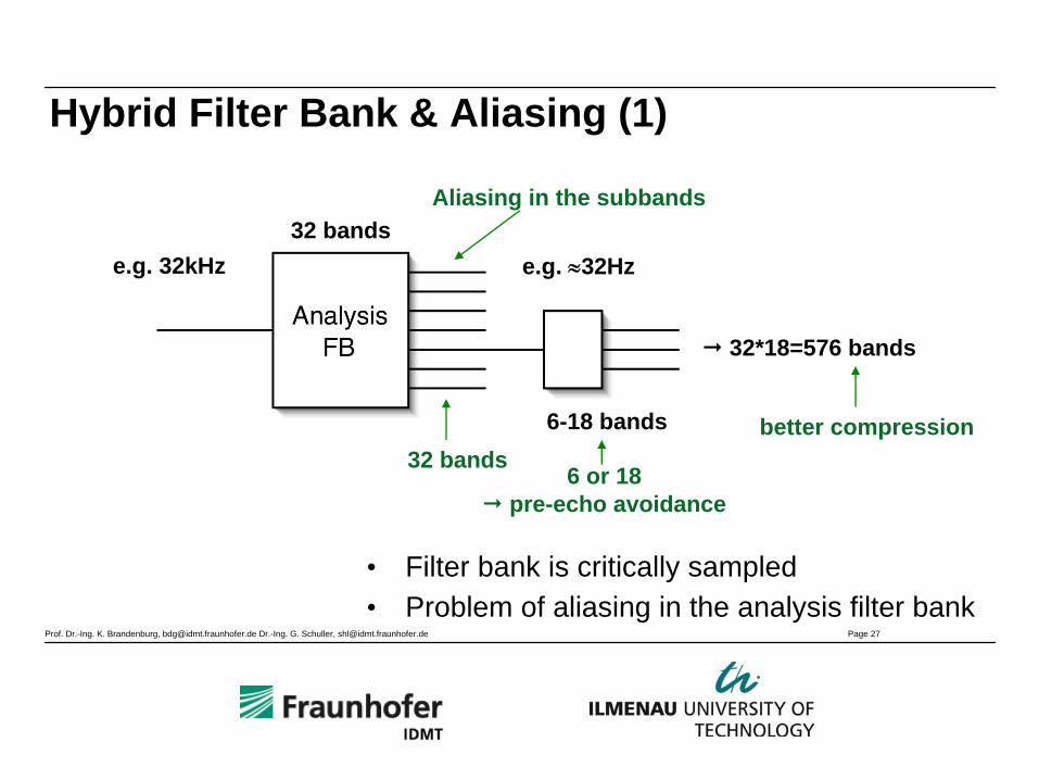
Hybrid Filter Bank & Aliasing (1)
e.g. 32kHz e.g. ≈32Hz32 bands
6-18 bands
32*18=576 bands
• Filter bank is critically sampled• Problem of aliasing in the analysis filter bank
Aliasing in the subbands
32 bands6 or 18
pre-echo avoidance
better compression

Prof. Dr.-Ing. K. Brandenburg, [email protected] Dr.-Ing. G. Schuller, [email protected] Page 28
Hybrid Filter Bank & Aliasing (2)
Nyquist frequencies/channel boundaries
ky
signal mirrored inside
3dB
aliasing cannot be neglected
Prof. Dr.-Ing. K. Brandenburg, [email protected] Dr.-Ing. G. Schuller, [email protected] Page 29
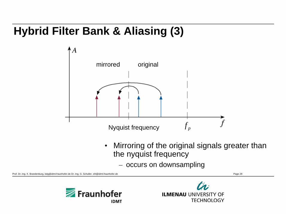
Hybrid Filter Bank & Aliasing (3)
• Mirroring of the original signals greater than the nyquist frequency
– occurs on downsampling
Nyquist frequency pf
mirrored original

Prof. Dr.-Ing. K. Brandenburg, [email protected] Dr.-Ing. G. Schuller, [email protected] Page 30
Problem of Aliasing in a Cascaded Filter Bank (1)• Result of cascading:
– Far off frequencies are aliased into the SB of the 2nd filter bank
Nyquist frequency
attenuation ofthe filter
subband of 1st FB
subbands of 2nd FB
signal aliased signal
first stagefilter bank
Observe:Aliasing spreadsover severalsubbands ofsecond stage!Not the case for only singlestage FB (practically)
Prof. Dr.-Ing. K. Brandenburg, [email protected] Dr.-Ing. G. Schuller, [email protected] Page 31
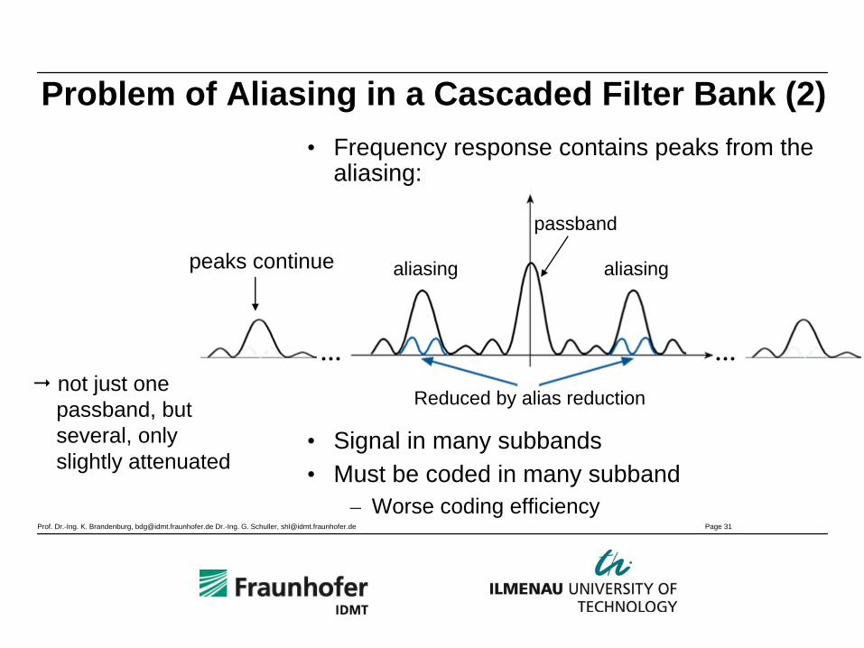
Problem of Aliasing in a Cascaded Filter Bank (2)• Frequency response contains peaks from the
aliasing:
• Signal in many subbands• Must be coded in many subband
– Worse coding efficiency
Reduced by alias reduction
passband
aliasing aliasing
not just onepassband, but several, onlyslightly attenuated
peaks continue
Prof. Dr.-Ing. K. Brandenburg, [email protected] Dr.-Ing. G. Schuller, [email protected] Page 32
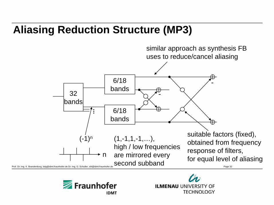
32bands
6/18bands
6/18bands
--
n
Aliasing Reduction Structure (MP3)similar approach as synthesis FBuses to reduce/cancel aliasing
(-1)n (1,-1,1,-1,…),high / low frequenciesare mirrored everysecond subband
suitable factors (fixed),obtained from frequency response of filters, for equal level of aliasing
Prof. Dr.-Ing. K. Brandenburg, [email protected] Dr.-Ing. G. Schuller, [email protected] Page 33
Problem of Aliasing in a Cascaded Filter Bank (3)
• Solution:– Less downsampling in first stage (non-critical
sampling)– better filter– Aliasing reduction with subtraction from
neighboring bands (e.g.MP3)– no cascaded filter bank (e.g. AAC)
Prof. Dr.-Ing. K. Brandenburg, [email protected] Dr.-Ing. G. Schuller, [email protected] Page 34
Huffman Coding Details• Vector coding
– One codeword for 2 or 4 subbands
• Escape sequence– Large words are coded as sum of
ESC-pointer + difference
• Adaptive table selection (signal table number)– Table selection according to maximum– Table selection according to local statistics
• Adaptive sectioning (4 sections)– Each section defines Huffman table
• Coding efficiency approaches theoretical limits !
Prof. Dr.-Ing. K. Brandenburg, [email protected] Dr.-Ing. G. Schuller, [email protected] Page 35
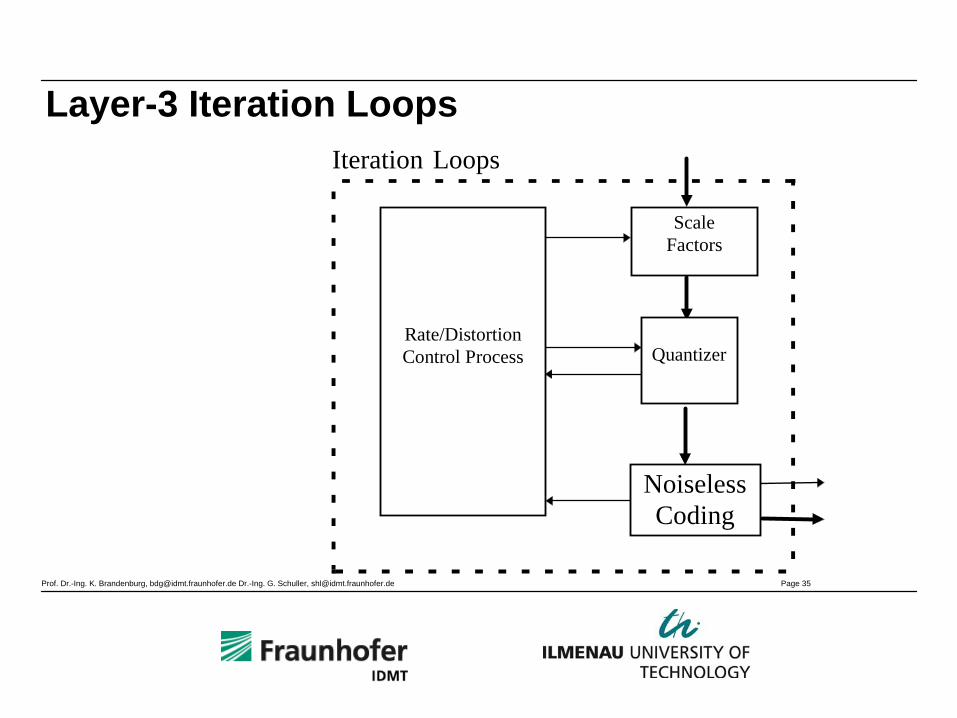
Layer-3 Iteration Loops
Rate/DistortionControl Process
ScaleFactors
Quantizer
NoiselessCoding
Iteration Loops

Prof. Dr.-Ing. K. Brandenburg, [email protected] Dr.-Ing. G. Schuller, [email protected] Page 36
Possibilities to control the Quantization
• Two basic ways– Bit Allocation– Noise Allocation
• Detailed possibilities:– Bit allocation between fixed „Worst-Case“ and
„Maximum-SNR“ situations– Bit allocation is calculated from the Threshold
Estimation– Direct calculation of the allowed noise (Noise
Allocation)– Simplified „Noise Allocation“
Prof. Dr.-Ing. K. Brandenburg, [email protected] Dr.-Ing. G. Schuller, [email protected] Page 37
Layer-3 : Outer Loop• Distortion Loop (control of the distortion)
• Saves the unquantized spectral values
• Compares the reconstructed values with the original
• Builds the actual distortion in the frequency domain
• Scaling by frequency groups with the amount of distortion
• Convergence of the iteration is not guaranteed
Prof. Dr.-Ing. K. Brandenburg, [email protected] Dr.-Ing. G. Schuller, [email protected] Page 38
Layer-3 : Inner Loop• Rate Loop (Data rate controller)
• Entropy coding: Data rate depends on actual data set
• Buffer Control: Controls the necessary bits
• Convergence through iterations: is always possible
• Beginning level: Calculated from SFM (Spectral Flatness Measure)
Prof. Dr.-Ing. K. Brandenburg, [email protected] Dr.-Ing. G. Schuller, [email protected] Page 39
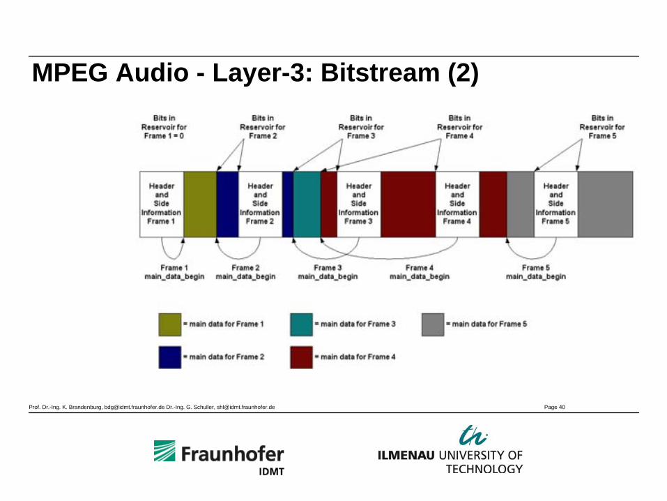
MPEG Audio - Layer-3: Bitstream• Organization of the bit streams• Fixed length of bytes: 17 at mono, 32 at
stereo, independent of the bitrate
• Constant Section– Header (ISO Standard, like with Layer-1 and -2)– Additional information for a frame (e.g. Pointer to the
variable section)– Additional information for each granule (e.g. Number
of the Huffman-Code table)• Variable Section
– Scalefactors– Huffman-coded frequency lines– Additional Data
Prof. Dr.-Ing. K. Brandenburg, [email protected] Dr.-Ing. G. Schuller, [email protected] Page 40
MPEG Audio - Layer-3: Bitstream (2)

Prof. Dr.-Ing. K. Brandenburg, [email protected] Dr.-Ing. G. Schuller, [email protected] Page 41
MPEG Audio - Layer-3: Bitstream (3)

Prof. Dr.-Ing. K. Brandenburg, [email protected] Dr.-Ing. G. Schuller, [email protected] Page 42
MPEG Audio - Layer-3: Bitstream (4)
Prof. Dr.-Ing. K. Brandenburg, [email protected] Dr.-Ing. G. Schuller, [email protected] Page 43
MPEG-1 Audio Decoder

Prof. Dr.-Ing. K. Brandenburg, [email protected] Dr.-Ing. G. Schuller, [email protected] Page 44
MPEG Audio – General Decoder Structure
Prof. Dr.-Ing. K. Brandenburg, [email protected] Dr.-Ing. G. Schuller, [email protected] Page 45
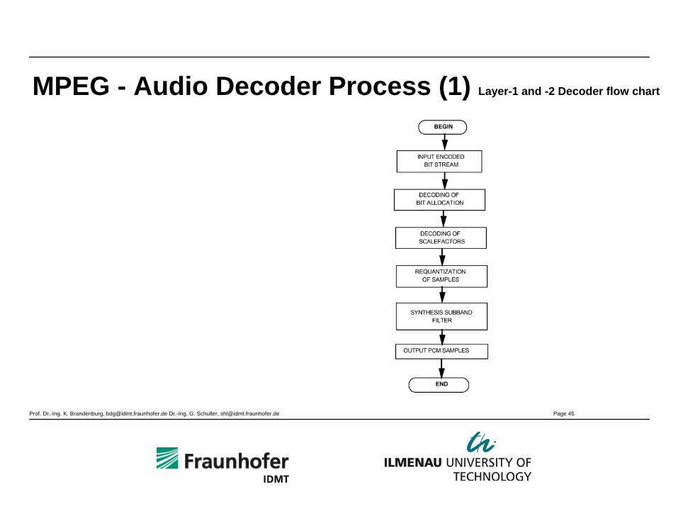
MPEG - Audio Decoder Process (1) Layer-1 and -2 Decoder flow chart

Prof. Dr.-Ing. K. Brandenburg, [email protected] Dr.-Ing. G. Schuller, [email protected] Page 46
MPEG - Audio Decoder Process (2) Layer-3 Decoder flow chart
Prof. Dr.-Ing. K. Brandenburg, [email protected] Dr.-Ing. G. Schuller, [email protected] Page 47
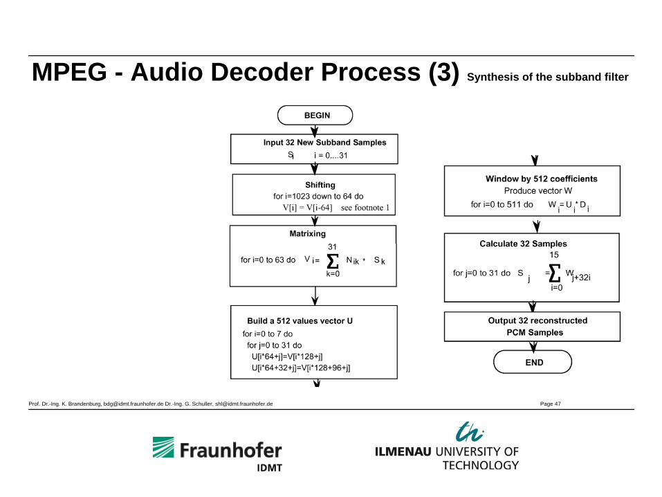
MPEG - Audio Decoder Process (3) Synthesis of the subband filter
Prof. Dr.-Ing. K. Brandenburg, [email protected] Dr.-Ing. G. Schuller, [email protected] Page 48
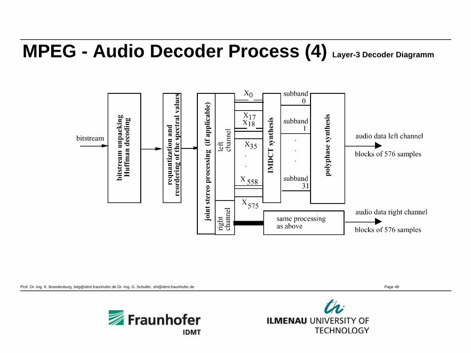
MPEG - Audio Decoder Process (4) Layer-3 Decoder Diagramm

Prof. Dr.-Ing. K. Brandenburg, [email protected] Dr.-Ing. G. Schuller, [email protected] Page 49
Stereo Coding in MPEG-1/-2
Prof. Dr.-Ing. K. Brandenburg, [email protected] Dr.-Ing. G. Schuller, [email protected] Page 50
MPEG Audio - Layer-1 and Layer-2
• For better stereo performance, Intensity Stereo (IS) can be applied
• With IS-Coding, a mono signal is transmitted in higher frequency bands and the decoder places it close to the original stereo position
Prof. Dr.-Ing. K. Brandenburg, [email protected] Dr.-Ing. G. Schuller, [email protected] Page 51
MPEG Audio - Layer-3 (3)
• "Joint Stereo"-Coding to additionally improve compression: Mid/Side coding (M/S) and Intensity Stereo (IS)
• M/S coding: two channels are coded where left is actually the sum of the original left and right and the right channel is the difference
• Either both channels are separately coded ("stereo"- mode) or "Intensity Stereo"-Coding is used

Prof. Dr.-Ing. K. Brandenburg, [email protected] Dr.-Ing. G. Schuller, [email protected] Page 52
MPEG-2 Audio
Prof. Dr.-Ing. K. Brandenburg, [email protected] Dr.-Ing. G. Schuller, [email protected] Page 53
MPEG-2 Audio LSR extensions:• Run coder at half the sampling rate• Only minor changes required (e.g. tables)⇒ Increased frequency resolution⇒Less bitrate for side information⇒Better coding efficiency⇒Only one half of the workload required
(SW implementations!)• But: Transparent coding not possible due
due restriction in bandwidth (max. 12 kHz)• All current MP3 decoders support this mode
Technical Background
Implications
Prof. Dr.-Ing. K. Brandenburg, [email protected] Dr.-Ing. G. Schuller, [email protected] Page 54
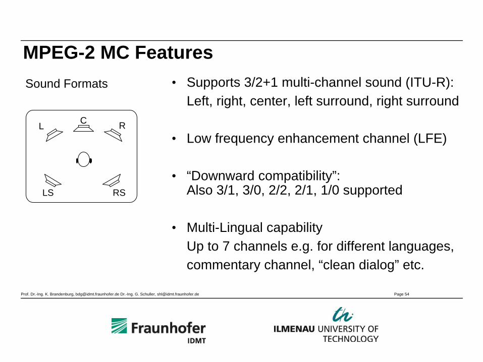
• Supports 3/2+1 multi-channel sound (ITU-R): Left, right, center, left surround, right surround
• Low frequency enhancement channel (LFE)
• “Downward compatibility”: Also 3/1, 3/0, 2/2, 2/1, 1/0 supported
• Multi-Lingual capabilityUp to 7 channels e.g. for different languages,commentary channel, “clean dialog” etc.
Sound Formats
L C R
LS RS
MPEG-2 MC Features
Prof. Dr.-Ing. K. Brandenburg, [email protected] Dr.-Ing. G. Schuller, [email protected] Page 55
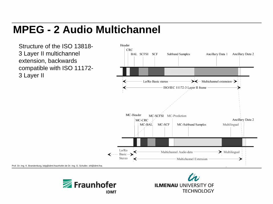
MPEG - 2 Audio MultichannelStructure of the ISO 13818- 3 Layer II multichannel extension, backwards compatible with ISO 11172- 3 Layer II

Prof. Dr.-Ing. K. Brandenburg, [email protected] Dr.-Ing. G. Schuller, [email protected] Page 56
Annex: Abbreviations and Companies

Prof. Dr.-Ing. K. Brandenburg, [email protected] Dr.-Ing. G. Schuller, [email protected] Page 57
Abbreviations and Companies (1)• AAC: Advanced Audio Coding• ASPEC: Adaptive Spectral Perceptual
Entropy Coding
• AT&T:American Telephone and Telegraph Company
• CCETT: Centre Commun d’Etudes de Télédiffusion et Télécommunication
• CNET: Research and Development Center of France Télécom
• FhG-IIS: Fraunhofer Gesellschaft/Institut fürIntegrierte Schaltungen (Erlangen)

Prof. Dr.-Ing. K. Brandenburg, [email protected] Dr.-Ing. G. Schuller, [email protected] Page 58
Abbreviations and Companies (2)• IRT: Institut für Rundfunktechnik GmbH,
München, Research and Development Instituteof ARD, ZDF, DLR, ORF and SRG
• ITU-R: International Telecommunication Union – Radio Communication Sector
• MASCAM: Masking-pattern Adapted SubbandCoding and Multiplexing AT&T:AmericanTelephone and Telegraph Company
• MUSICAM: Masking-pattern Universal Subband Integrated Coding and Multiplexing
Prof. Dr.-Ing. K. Brandenburg, [email protected] Dr.-Ing. G. Schuller, [email protected] Page 59
Abbreviations and Companies (3)
• NTT: Nippon Telegraph and Telephone Corp./Human Interface Laboratories
• Thomson: Thomson, Telefunken, Saba, RCA, GE, ProScan
• TwinVQ: Transform-domain Weighted Interleave Vector Quantization