
The analysis of thermal-oil heating systems with exhaust ...
8
Zeszyty Naukowe 24(96) 33 Scientific Journals Zeszyty Naukowe Maritime University of Szczecin Akademia Morska w Szczecinie 2010, 24(96) pp. 33–40 2010, 24(96) s. 33–40 The analysis of thermal-oil heating systems with exhaust gas heaters on motor ships Analiza olejowych systemów grzewczych z nagrzewnicami utylizacyjnymi na statkach motorowych Ryszard Michalski, Wojciech Zeńczak West Pomeranian University of Technology, Faculty of Maritime Technology Department of Heat Engines and Marine Power Plants Zachodniopomorski Uniwersytet Technologiczny, Wydział Techniki Morskiej Katedra Maszyn Cieplnych i Siłowni Okrętowych 71-065 Szczecin, al. Piastów 41, e-mail: [email protected], [email protected] Key words: ship’s heating system, thermal oil heater, exergetic analysis Abstract The article characterises the properties of steam and special thermal oils as the basic heating media on motor ships. The features of the heating installations have been presented with the particular attention drawn to thermal oil installations in which exhaust gas heaters have been employed. Also an example of the comparative exergetic analysis has been included demonstrating the comparison between steam generation in exhaust gas boiler and oil heating system in the heater, assuming the identical heat flux transferred in the boiler and the heater from the exhaust gas to the heating medium (steam and thermal oil) and assuming identical increase of exhaust gas entropy in the heat exchangers under examination. Słowa kluczowe: okrętowy system grzewczy, nagrzewnice olejowe, analiza egzergetyczna Abstrakt W referacie scharakteryzowane zostały własności pary wodnej i specjalnych olejów grzewczych jako pod- stawowych czynników grzewczych na statkach motorowych. Przedstawiono cechy instalacji grzewczych ze szczególnym uwzględnieniem instalacji olejowych, w których występują nagrzewnice utylizacyjne. Zamies z- czono także przykład porównawczej analizy egzergetycznej systemu wytwarzania pary w kotle utylizacyjnym oraz systemu podgrzewania oleju w nagrzewnicy przy założeniu jednakowego strumienia ciepła przekazywa- nego w kotle i nagrzewnicy od spalin do czynnika grzewczego (pary wodnej i oleju) oraz przy założeniu je d- nakowego przyrostu entropii spalin w rozpatrywanych wymiennikach ciepła. Introduction Mostly steam and special thermal oils have been applied as heating media on ships. Water or hot air have been used in a lesser degree and electric energy is used just occasionally. To obtain the high temperature of the heated media by using such media as water or steam it is necessary to apply sufficiently high pressure. The high pressure of steam is also necessary to make up for the pressure losses in the long cargo heating pipelines on some tankers. This fact increases the risk of the loss of tightness and steam leakages and its condensate to the heated working media as well as to the cargo. This is absolutely not allowed, in particular while heating the concentrated acids and bases or liquid sulphur. In such cases, as well as on many other ship types, the special thermal-oils have been used as heat carriers which are characterised by the relatively stable physical and chemical properties within the broad range of the changes of their working temperatures. Additionally the oil heating systems are significant for their higher efficiency values as compared to the steam systems, do not
Transcript of The analysis of thermal-oil heating systems with exhaust ...
Zeszyty Naukowe 24(96) 33
Scientific Journals Zeszyty Naukowe Maritime University of Szczecin Akademia Morska w Szczecinie
2010, 24(96) pp. 33–40 2010, 24(96) s. 33–40
The analysis of thermal-oil heating systems with exhaust gas heaters on motor ships
Analiza olejowych systemów grzewczych z nagrzewnicami utylizacyjnymi na statkach motorowych
Ryszard Michalski, Wojciech Zeńczak
West Pomeranian University of Technology, Faculty of Maritime Technology Department of Heat Engines and Marine Power Plants Zachodniopomorski Uniwersytet Technologiczny, Wydział Techniki Morskiej Katedra Maszyn Cieplnych i Siłowni Okrętowych 71-065 Szczecin, al. Piastów 41, e-mail: [email protected], [email protected]
Key words: ship’s heating system, thermal oil heater, exergetic analysis
Abstract The article characterises the properties of steam and special thermal oils as the basic heating media on motor
ships. The features of the heating installations have been presented with the particular attention drawn to
thermal oil installations in which exhaust gas heaters have been employed. Also an example of the
comparative exergetic analysis has been included demonstrating the comparison between steam generation in
exhaust gas boiler and oil heating system in the heater, assuming the identical heat flux transferred in the
boiler and the heater from the exhaust gas to the heating medium (steam and thermal oil) and assuming
identical increase of exhaust gas entropy in the heat exchangers under examination.
Słowa kluczowe: okrętowy system grzewczy, nagrzewnice olejowe, analiza egzergetyczna
Abstrakt W referacie scharakteryzowane zostały własności pary wodnej i specjalnych olejów grzewczych jako pod-
stawowych czynników grzewczych na statkach motorowych. Przedstawiono cechy instalacji grzewczych ze
szczególnym uwzględnieniem instalacji olejowych, w których występują nagrzewnice utylizacyjne. Zamiesz-
czono także przykład porównawczej analizy egzergetycznej systemu wytwarzania pary w kotle utylizacyjnym
oraz systemu podgrzewania oleju w nagrzewnicy przy założeniu jednakowego strumienia ciepła przekazywa-
nego w kotle i nagrzewnicy od spalin do czynnika grzewczego (pary wodnej i oleju) oraz przy założeniu jed-
nakowego przyrostu entropii spalin w rozpatrywanych wymiennikach ciepła.
Introduction
Mostly steam and special thermal oils have been
applied as heating media on ships. Water or hot air
have been used in a lesser degree and electric
energy is used just occasionally. To obtain the high
temperature of the heated media by using such
media as water or steam it is necessary to apply
sufficiently high pressure. The high pressure of
steam is also necessary to make up for the pressure
losses in the long cargo heating pipelines on some
tankers. This fact increases the risk of the loss of
tightness and steam leakages and its condensate to
the heated working media as well as to the cargo.
This is absolutely not allowed, in particular while
heating the concentrated acids and bases or liquid
sulphur. In such cases, as well as on many other
ship types, the special thermal-oils have been used
as heat carriers which are characterised by the
relatively stable physical and chemical properties
within the broad range of the changes of their
working temperatures. Additionally the oil heating
systems are significant for their higher efficiency
values as compared to the steam systems, do not

Ryszard Michalski, Wojciech Zeńczak
34 Scientific Journals 24(96)
post the corrosion danger, are suitable for the full
automation which allows their unmanned operation.
The heat source in the ship’s heating systems is the
energy coming from the combustion of fuels in the
steam boilers or oil heaters. On the motor ships in
high degree the waste heat energy is used in the
form of the heat contained in the main engines
exhaust gases.
Steam heating system
In the heating technology the saturated steam
(dry or humid) is generally used, less frequently
the slightly superheated steam. The advantage of
the steam in relation to the other heating media is
its constant temperature within the condensation
process. The significant parameters of steam, as the
heating medium, are the temperature and saturation
pressure. As generally known, these values are
closely interrelated. Thus the application of high
pressure steam requires adequately high pressure
values throughout the entire installation. The steam
working temperature determines indirectly the
required strength of the equipment used in the
steam installation.
Another important parameter is the water evapo-
ration specific enthalpy whose value decreases
together with the pressure rise and the increase
of the saturation temperature. It reaches the value
equivalent to zero in the critical conditions (pk =
22.1 MPa, Tk = 647.3 K). From this point of view in
the heating installations there should be used steam
of low pressure corresponding to the large value of
the evaporation enthalpy. Within the practically
used pressure range the value of the saturated steam
specific enthalpy increases together with the pres-
sure rise. The heating steam higher pressure values
correspond to its higher density which allows the
application of lower diameter pipelines. However,
it should be reminded that together with the pres-
sure increase the water evaporation specific en-
thalpy decreases which affects the heat exchange
surface of the heaters. The finally adopted working
parameters of the heating system are usually based
on compromise. However it should be emphasised
that the choice of the heating steam pressure chiefly
depends on the temperature values to which the
working media are to be heated in engine room.
In the engine rooms of the ships which do not carry
the heating requiring cargo the saturated steam
under 0.4–0.8 MPa is used which correspond to the
saturation temperature 416.75–443.57 K accord-
ingly. The steam pressure values on tankers reach
as high as 1.2 MPa (saturation temperature of
461.1 K). The reason to choose the higher pressure
values in such cases are inter alia larger pressure
drops of steam in the long pipelines, a possibility of
the reduction of the steam supply piping diameters,
the reduction of heat exchange surface resulting
from the higher temperatures and the ensuring of
the heating medium and condensate flow without
any additional equipment [1].
The condensate leaving the heaters is cooled
down to the temperature approximately 343 K in
the condensate cooler or in case of not excessively
high temperatures – in hotwell. This operation is
necessary to provide the protection for the boiler
feed pump against cavitation and water evaporation
in the suction stub pipe. However it causes some
significant heat losses in the steam-water installa-
tion thus visibly reducing the efficiency of the
steam heating system.
Oil heating systems
The heating oils can be divided on account of
their origin into the mineral and synthetic ones. The
mineral oils, of natural origin, consist the mixture
of many hydrocarbons, amongst which the satu-
rated paraffin hydrocarbons are of the biggest im-
portance. The chemical structure of mineral oils is
very much varied and depends to a large extent on
the origin of the raw material and the methods of its
processing in the refineries. In the effect the proper-
ties of the mineral oils are hardly reproducible and
keep on changing in various manners during the
use. The mineral oils may be used in the heating
systems where the temperature of the medium does
not exceed 593.15 K. In case of the necessity to use
higher working temperatures the synthetic oils are
applied which are the products of closely monitored
chemical synthesis. Their chemical composition is
more stabilised therefore they are easier reprodu-
cible in the production in various factories which
means keeping their properties as the same. Since
the majority of the motor ships has no need to heat
the working media up to very high temperatures,
and the heat supply to the thermal oil is effected
mainly in the exhaust gas heaters, the preferable
heat carriers are the mineral oils. At the same time
these are cheaper than the synthetic oils, easier
available and non-toxic.
The thermal oils of less density have better
thermal properties and provide better heat condu-
ctivity. In case of thermal oils an important parame-
ter is their viscosity because it influences the flow
rate and nature, thus the intensity of the heat ex-
change and provides the possibility of oil pumping
in low temperatures. The relatively low viscosity of
thermal oils and the large value of viscosity index
The analysis of thermal-oil heating systems with exhaust gas heaters on motor ships
Zeszyty Naukowe 24(96) 35
ensures the high coefficients of heat exchange and
the constant properties within the wide temperature
range as well we facilitates oil circulation while
starting the heating system in low temperatures.
Another significant parameter is also the solidifica-
tion temperature. This is used to evaluate the pos-
sibility of oil storage and transfer and its flow
capacity inside the gravity-supplied system in low
temperatures.
The mineral oils as opposed to the popular
synthetic oils are characterised by the vapour low
pressure (the less as the higher oil viscosity is).
At the maximum working temperature it is usually
lower than the atmospheric pressure owing to
which it is possible to use so called non-pressure
heating systems. In case it is necessary to use the
higher temperatures, the need arises to apply, eg
inside expansion tank, a minor overpressure of the
inert gas, usually nitrogen or the adoption of the
hermetic installations to prevent the formation of
the vapour-locks.
The minimum working temperature of the
heating system is determined by the oil capacity to
circulate through the heater prior to its starting. The
minimum temperature determinant is the corres-
ponding oil viscosity with which the pumps are still
capable of oil pumping (ca 300 cSt) [2].
Theoretically, in the oil heating installation the
oil may be heated below the temperature deter-
mining the beginning of its boiling (the temperature
where the oil vapour pressure is equal to the
ambient pressure). In practice the upper working
temperature is limited by the value where oil
thermal decomposition rapidly increases).
An important parameter is the specific heat ca-
pacity of the heating medium. It influences the in-
tensity of its heat transfer in the heating systems.
A strong relation of its value to the temperature
should be noted. For example at the temperature of
273.15 K the mineral oil heat capacity ranges
within 1.76–1.83 kJ/kgK), whereas at the tempera-
ture of 573.15 K it ranges within 2.83–3.02 kJ/kgK.
The heat capacity values of the synthetic oils are
less than those of the mineral oils [2]. As can be
seen these are values approximately twice less than
for the water. This means that the oils require twice
as big flow (larger energy consumption) or the
increase of the heat flux in oil heater (large and
expensive boilers).
The heat conductivity of the mineral oils which
is of major significance in the heat exchange, at the
temperature of 273.15 K ranges within 0.129–0.135
W/mK, whereas at the temperature of 573.15 K it is
within 0.11–0.114 W/mK [2]. This is higher than
the specific heat capacity of the synthetic oils.
Oil during the operation within the heating sys-
tem changes its chemical properties which is collo-
quially referred to as the oil deterioration. These
changes are mainly caused by the oxidation and
thermal cracking, particularly in higher tempera-
tures. The visible results of oil deterioration are the
collecting of harmful substances such as resins and
coal sediments. The sediments are partly suspended
in oil and partly precipitated and deposited on the
parts of the installation, and the additionally gene-
rated organic acids have a corroding effect on
metals. Also oil viscosity changes in a high degree
in the result of the generation of compounds of
larger molecular weight [3, 4].
Exergetic analysis [5] may become helpful for
the calculations of the thermal processes, particu-
larly effected within the relatively low temperatures
of the working media. For this purpose it is useful
to find the specific exergy of the working media
participating in the processes under investigation.
Assuming that the oil pressure does not exceed
0.3 MPa or is equal to the ambient pressure (in the
non-pressure systems) and that the specific heat
capacity value is constant, its specific exergy can be
calculated from the equation (1).
ot
ototpfTT
TTTTcb ln (1)
where: cp – oil specific heat capacity, T – oil tem-
perature, Tot – ambient temperature.
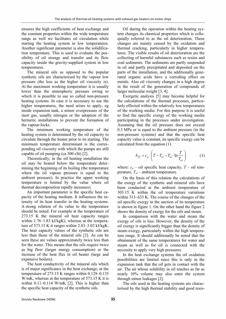
On the basis of this relation the calculations of
the exergy of the synthetic and mineral oils have
been conducted at the ambient temperature of
303.15 K within the oil temperature variations
within 313–633 K. The course of the changes of the
oil specific exergy in the unction of its temperature
is shown in figure 1. On the other hand the figure 2
shows the density of exergy for the oils and steam.
In comparison with the water and steam the
exergy of oils is less. However, the density of the
oil exergy is significantly bigger than the density of
steam exergy, particularly within the high tempera-
ture range. It should additionally be noted that the
obtainment of the same temperatures for water and
steam as well as for oil is connected with the
necessity to apply very high pressures.
In the heat exchange systems the oil oxidation
possibilities are limited since this is only in the
expansion tank that the oil gets in contact with the
air. The air whose solubility in oil reaches as far as
nearly 10% volume may also enter the system
through minor leakages [2].
The oils used in the heating systems are charac-
terised by the high thermal stability and good resis-
Ryszard Michalski, Wojciech Zeńczak
36 Scientific Journals 24(96)
tance to oxidation within the temperature ranges
occurring in service. Owing to that the rate of their
decomposition and oxidation is small which en-
sures long period of oil usability without formation
of sludge and sediments which are likely to be the
cause of the disturbances in the operation of the
heating system. It should be noted that the synthetic
thermal oils ensure better thermal stability and
higher resistance to oxidation as compared to the
mineral oils.
The most important feature thanks to which the
thermal oils tend to substitute the steam as the
heating medium is the possibility of their appli-
cation at the low values of the working pressures
whose value depends almost entirely on the flow
resistance in the heating installations. Thermal oil
installation is either the installation of the open
type, “non-pressure” (the oil compensation tank is
connected with the atmosphere), or the closed type,
low-pressure with pressure values not exceeding
0.1–0.3 MPa [6]. This enables to obtain the
temperatures up to 593.15 K for mineral oils or
up to 633.15 K for the synthetic oils remaining in
the liquid stage. The achieving of such high tempe-
ratures of the heating steam would require the
application of significantly more expensive, high-
-pressure steam installation. Therefore the first
ships where the oil heating system has been applied
have been the tankers designed to carry heavy
petroleum products, eg bitumen, asphalt where the
required heating up temperatures are in the order of
493.15 K (the application of the steam system
would necessitate the used of steam under 4 MPa).
In case of the application of the cargo thermal oil
heating, the system generally is used also to cover
the remaining heating needs of a ship.
In the open type installations oils of large
viscosity are used which are characterised by the
high flashpoint ensuring better work safety. The
closed type installations with oil of low viscosity
are, however, more efficient [2].
In case the heating installation is put out of
operation, the application of oil to heat up the
petroleum product cargoes eliminates the possibi-
lity of the petroleum products entering the heating
medium which might take place in the steam
heating systems. This phenomenon is prevented by
placing the oil expansion tank at the highest point
of the entire installation [7].
If on ship’s board there is a need of steam, eg to
conduct the technological processes (on fish factory
trawlers, for tank cleaning, ice removal etc), it can
be additionally produced in the steam generators
heated with thermal oil.
The overall thermal efficiency of the thermal oil
installation, reaching the value within 0.75–0.85, is
higher than the efficiency of the steam installation
(0.55–0.65) owing to the elimination of the heat
losses occurring in the steam installations at the
condensate side. Also the working medium losses
in the thermal oil installations are smaller than the
medium losses in the steam heating installations
[7].
Owing to the possibility to apply the higher
temperatures of the working medium in the thermal
oil installations, there is no need to increase the
heat exchange surface, and the low pressure pre-
vailing in these installations causes that the invest-
ment costs of such installations do not increase in
comparison to the conventional steam installations.
An opportunity to reduce the heat exchange surface
within the oil heating process is the application of
the fluidised-bed heaters, both for exhaust gas as
well as the independent, oil-fired ones.
Fig. 1. The physical specific exergy values for the synthetic
and mineral oils and dry saturated steam in the function of the
temperature Tot = 303.15 K
Rys. 1. Egzergie fizyczne właściwe olejów: syntetycznego
i mineralnego oraz pary wodnej nasyconej suchej w temepera-turze Tot = 303,15 K
Fig. 2. The density of the physical exergy values of synthetic
and mineral oils and dry saturated steam in the function of the
temperature Tot = 303.15 K
Rys. 2. Gęstość egzergii fizycznych olejów: syntetycznego
i mineralnego oraz pary wodnej nasyconej suchej w funkcji
temperatury Tot = 303,15 K
Sp
ecif
ic e
xer
gy,
kJ/
kg
E
xer
gy d
ensi
ty, k
J/m
3
Temperature, K
Temperature, K
Min. oil Synth. oil Steam
Min. oil Synth. oil Steam
The analysis of thermal-oil heating systems with exhaust gas heaters on motor ships
Zeszyty Naukowe 24(96) 37
The basic arrangements of the thermal oil heating installations with the exhaust gas heaters
In order to increase the general efficiency of
ship’s engine room / power plant there are used the
combined systems of thermal oil heating of the
heating medium in the independent heater and in
the exhaust gas heater utilising the main engines’
and at times also auxiliary engines’ exhaust gases.
Both heaters can operate separately and / or jointly,
ie in the parallel or series set-up. In the series
operation as first the low temperature exhaust gas
heater is applied. The parallel connection is applied
in case when the large heat amounts are necessary
for the cargo heating in cargo tanks of the ship. The
oil-fired heater is automatically started, if the heat
needs exceeds the exhaust gas heater production
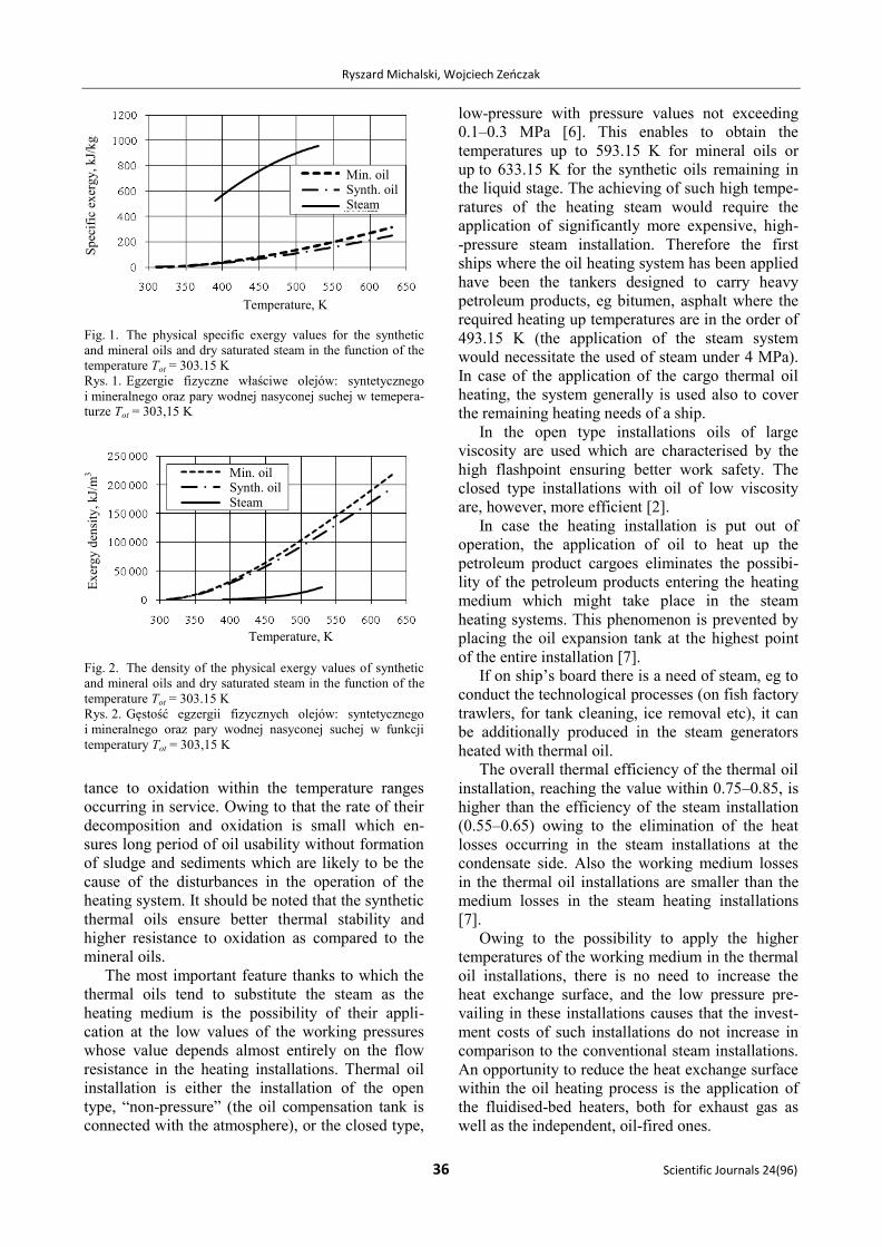
capacity. The figure 3 shows for instance the instal-
lation with the exhaust gas heater operating in the
series set-up with the independent heater.
Thermal oil heating installations with the inde-
pendent and exhaust gas heater can totally replace
the steam installations on the majority of ships.
Most frequently they are employed on: tankers for
the carriage of high viscosity petroleum products,
container ships, fish factory trawlers operating in
Arctic waters, chemical tankers, ice-breakers.
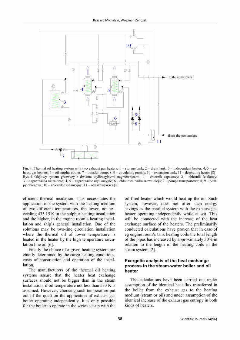
In case of ship’s indirect propulsion with two
medium-speed Diesel engines it is possible to apply
two exhaust gas oil heaters which may operate in
the parallel system or the series system (Fig. 4).
Operation in the series system with the independent
heater is also possible. Such arrangement provides
possibilities of the heating system operation with
various connection versions. This enables rational
generation and use of energy [8].
More complex thermal oil installations are ap-
plied on tanker used for the carriage of molten sul-
phur. The sulphur during the transport should be
stored at the temperature within 408.15–423.15 K
when it shows the smallest viscosity and does not
change its properties. The temperature increase
above this value causes that the sulphur viscosity
increases and it densifies around heating coils stick-
ing to the pipes, which in effect creates their
Fig. 3. Oil heating installations by means of the independent and exhaust gas heaters operating in the series set-up; 1 – independent
heater; 2 – exhaust gas heater; 3 – expansion tank; 4, 5 – circulating pumps; 6 – drain tank; 7 – storage tank; 8 – topping-up
pump / replenish pump; 9 – oil cooler; 10 – deaerating heater [2]
Rys. 3. Instalacja podgrzewania oleju nagrzewnicą niezależną i utylizacyjną w układzie szeregowym; 1 – nagrzewnica niezależna;
2 – nagrzewnica utylizacyjna; 3 – zbiornik wyrównawczy; 4, 5 – pompy cyrkulacyjne; 6 – zbiornik ściekowy; 7 – zbiornik zapaso-
wy; 8 – pompa uzupełniająca; 9 – chłodnica oleju; 10 – podgrzewacz [2]
to the consumers
from the consumers
Ryszard Michalski, Wojciech Zeńczak
38 Scientific Journals 24(96)
efficient thermal insulation. This necessitates the
application of the system with the heating medium
of two different temperatures, the lower, not ex-
ceeding 433.15 K in the sulphur heating installation
and the higher, in the engine room’s heating instal-
lation and ship’s general installation. One of the
solutions may be two-line circulation installation
where the thermal oil of lower temperature is
heated in the heater by the high temperature circu-
lation line oil [6].
Finally the choice of a given heating system are
chiefly determined by the cargo heating conditions,
costs of construction and operation of the instal-
lation.
The manufacturers of the thermal oil heating
systems assure that the heater heat exchange
surfaces should not be bigger than in the steam
installation, if oil temperature not less than 533 K is
assumed. However, choosing such temperature put
out of the question the application of exhaust gas
boiler operating independently. It is only possible
for the boiler to operate in the series set-up with the
oil-fired heater which would heat up the oil. Such
system, however, does not offer such energy
savings as the parallel system with the exhaust gas
heater operating independently while at sea. This
will be connected with the increase of the heat
exchange surface of the heaters. The preliminarily
conducted calculations have proven that in case of
eg engine room’s tank heating coils the total length
of the pipes has increased by approximately 30% in
relation to the length of the heating coils in the
steam system [2].
Exergetic analysis of the heat exchange process in the steam-water boiler and oil heater
The calculations have been carried out under
assumption of the identical heat flux transferred in
the boiler from the exhaust gas to the heating
medium (steam or oil) and under assumption of the
identical increase of the exhaust gas entropy in both
kinds of heaters.
Do odbiorników
Z odbiorników
3
6 8
9
11
4 5
7
10
to the consumers
from the consumers
Fig. 4: Thermal oil heating system with two exhaust gas heaters; 1 – storage tank; 2 – drain tank; 3 – independent heater; 4, 5 – ex-
haust gas heaters; 6 – oil surplus cooler; 7 – transfer pump; 8, 9 – circulating pumps; 10 – expansion tank; 11 – deaerating heater [8]
Rys. 4. Olejowy system grzewczy z dwiema utylizacyjnymi nagrzewnicami; 1 – zbiornik zapasowy; 2 – zbiornik ściekowy;
3 – nagrzewnica niezależna; 4, 5 – nagrzewnice utylizacyjne; 6 – chłodnica nadmiarowa oleju; 7 – pompa transportowa; 8, 9 – pom-
py obiegowe; 10 – zbiornik ekspansyjny; 11 – odgazowywacz [8]

The analysis of thermal-oil heating systems with exhaust gas heaters on motor ships
Zeszyty Naukowe 24(96) 39
The ratio of the increase of the entropy of the
heating media (steam and oil) has been determined
as:
wzpp
ol
olpolol
p
ol
ssm
T
Tcm
S
S
ln
(2)
ololpol
wzpp
olTTc
iimm
(3)
thus:
ololwzp
ol
olwzp
p
ol
TTss
T
Tii
S
S
ln
(4)
where: pol mm , – stream of oil or generated steam;
pp is , – entropy and specific enthalpy of the steam
at the saturation line; wzw is , – entropy and specific
enthalpy of the boiler feed pump; olol TT , – thermal
oil temperature at the heater outlet and inlet; polc –
thermal oil specific heat capacity (constant value
assumed).
For the purposes of comparison of the steam and
oil systems the constant value of the oil temperature
has been assumed at the return to the heater (Tol1 =
303.15 K). On the other hand, the temperatures of
boiler feed water (Tw1) have been changed within
323.15–343.15 K. As displayed by the calculations
performed, the increase of the temperature of both
media at the outlet from the heat exchangers, with
the assumed identical exhaust gas entropy incre-
ases, bigger increases of the entropy of the thermal
oil do occur than the increases in water and steam
entropy. This leads to the bigger increase of entropy
within the process of oil heating as compared to the
water and steam heating. This is the result of the
faster drop in entropy increase in the steam
generation process in relation to the thermal oil
heating system. However, it should be noted that
the higher temperatures of steam correspond to
higher saturation pressures and lower evaporation
enthalpy. The courses of the changes in the entropy
increases are illustrated by the curves in figure 5.
It should be noted that the increase in the boiler
feed water temperature is accompanied by the
growth of the ratio of the increase of the oil entropy
to the increase of water and steam entropy. Similar
as in figure 5 is the nature of the course of the
curves in figure 6, illustrating the ratio of the in-
crease of the entropy of oil to the increase of the
entropy of water and steam in the function of the
heating media temperature for the various tempera-
tures of oil at the heater inlets with the boiler feed
water constant temperature (Tw1 = 303.15 K).
1.08
1.09
1.10
1.11
1.12
1.13
1.14
1.15
1.16
425 435 445 455 465 475 485 495 505 515 525 535 545 555 565 575
Rat
io o
fth
e en
tro
py
in
crea
ses
of
ther
m.
oil
an
d w
ate
r an
d s
team
Temperature, K
Tw1 = 323.15 K
Tw1 = 333.15 K
Tw1 = 343.15 K
Fig. 5. The ratio of the increase of the oil entropy to the
increase of the water and steam entropy in the function of the
temperature of the heating media for various temperatures of
boiler feed water Tw1. Oil temperature at the heater inlet Tol1 =
343.15 K
Rys. 5. Stosunek przyrostu entropii oleju do przyrostu entropii
wody i pary w funkcji temperatury czynników grzewczych dla
różnych temperatur wody zasilającej kocioł Tw1. Temperatura
oleju na wejściu do nagrzewnicy Tol1 = 343,15 K
0.97
0.98
0.99
1.00
1.01
1.02
1.03
1.04
1.05
1.06
1.07
445 455 465 475 485 495 505 515 525 535 545 555 565 575
Rat
io o
fth
e en
tro
py
in
crea
ses
of
ther
m.
oil
an
d w
ate
r an
d s
team
Temperature, K
Tol1 = 400.15 K
Tol1 = 423.15 K
Tol1 = 443.15 K
Fig. 6. The ratio of the increase of oil entropy to the increase
of water and steam entropy in the function of the heating media
temperature for the various temperatures of thermal oil Tol1.
The temperature of boiler feed water Tw1 = 303.15 K.
Rys. 6. Stosunek przyrostu entropii oleju i pary w funkcji
temperatury czynników grzewczych dla różnych temperatur
oleju grzewczego Tol1.Temperatura wody zasilającej kocioł
Tw1 = 303,15 K
The increase in the working media temperature
causes that the ratio of the entropy increase of the
oil in oil exhaust gas heater in relation to the entro-
py increase of the water and steam in exhaust gas
boiler grows. With the lower temperature range the
increases of entropy in the oil boiler may be lower
than in the steam boiler. The increase of the oil
Tw1 Tw1 Tw1
Tol1
Tol1
Tol1
Rat
io o
f th
e en
tro
py
incr
ease
s o
f th
em.
oil
and
wat
er a
nd
ste
am
Rat
io o
f th
e en
tro
py
incr
ease
s o
f th
em.
oil
and
wat
er a
nd
ste
am
Ryszard Michalski, Wojciech Zeńczak
40 Scientific Journals 24(96)
temperature on the return line to the heaters causes
that entropy increases get less, thus the ratio of the
increase of entropy of the oil system in relation to
the steam system gets smaller for the same values
of oil and water temperatures at the outlets of the
boilers. This is the case in the actual systems where
the thermal oil temperature at the return to the hea-
ter is significantly higher than the boiler feed water
temperature.
The analysis conducted covered only one link in
the entire chain of transformations related with the
heating process on a ship. Similarly conducted
analysis for the remaining elements of the whole
heating system will allow to fully evaluate their
efficiency. The outline of such analysis has been
presented in [8].
Conclusions
The analysis of the thermal oil systems pre-
sented in the article shows that they might form
a good alternative for the steam system which is
nowadays commonly used on the majority of ships.
The advantages of the thermal oil system have been
observed and appreciated already long ago, inter
alia in the German shipyards where ships are very
often equipped with the installations of such type.
The shipowners reluctance to the application of
such solutions may result from the limited know-
ledge of the thermal oil systems. The smaller heat
exchange surfaces in the steam-water installations
in comparison to the oil systems are accompanied
by the high costs of the high pressure installation
and the steam boiler itself as well as the additional
equipment such as boiler water treatment plant,
inspection tanks, condensate cooler, dehydrators
etc. as well as their lower efficiency. The economic
advantages to be achieved through the application
of the thermal oil systems include amongst others
fuel savings and the savings of the ship’s mainte-
nance costs owing to their longer life and unat-
tended / unmanned operation.
References
1. MICHALSKI R., ZEŃCZAK W.: Ocena efektywności okręto-
wych systemów grzewczych. Marine Technology 2000,
Międzynarodowa XIX Sesja Naukowa Okrętowców,
Szczecin–Dziwnówek 2000, 201–210.
2. MICHALSKI R., ZEŃCZAK W.: Porównanie olejowego sys-
temu grzewczego z parowym na przykładzie jednostki
B-578. Explo-Ship’99, WSM, Szczecin 1999, 99–107.
3. MICHAŁOWSKA J.: Paliwa, oleje, smary. WKiŁ, Warszawa
1983.
4. OETINGER J.: Preventing Fires in Thermal Oil Heat-
Transfer Systems. Evaluating fire risks effectively, Chemi-
cal Processing, July 2001.
5. MICHALSKI R.: Wybrane zagadnienia analizy termodyna-
micznej parowych i olejowych systemów grzewczych na
statku. XXII Sympozjum Siłowni Okrętowych SymSO
2001. Wyd. Politechniki Szczecińskiej, Szczecin 2001,
183–188.
6. PEREPECZKO A.: Instalacje eksploatacyjne zbiornikowców.
WSM, Gdynia 1991.
7. URBAŃSKI P.: Paliwa i smary. Wyd. Politechniki Gdań-
skiej, Gdańsk 1997.
8. MICHALSKI R., ZEŃCZAK W.: Okrętowe olejowe systemy
grzewcze przysposobione do odzyskiwania energii odpa-
dowej, Zagadnienia Eksploatacji Maszyn, Radom 2003,
1(133), 38, 107–127.
The study financed from the means for
the education within 2009–2012 as own research
project No. N N509 404536.
Recenzent:
dr hab. inż. Andrzej Adamkiewicz, prof. AM
Akademia Morska w Szczecinie