![INSTYTUT PODSTAWOWYCH PROBLEMÓW TECHNIKIprace.ippt.gov.pl/IFTR_Reports_2_2001.pdf · 2013-08-01 · Chaotic vibrations, an introduction for applied scientists and engineers [1],](https://static.fdocuments.pl/doc/165x107/5f0d15797e708231d438995f/instytut-podstawowych-problemw-2013-08-01-chaotic-vibrations-an-introduction.jpg)
THERMAL FATIGUE OF THE SELECTED TOOL STEEL APPLIED … · THERMAL FATIGUE OF THE SELECTED TOOL...
5
A R C H I V E S O F M E T A L L U R G Y A N D M A T E R I A L S Volume 58 2013 Issue 3 DOI: 10.2478/amm-2013-0067 J. ZYCH * THERMAL FATIGUE OF THE SELECTED TOOL STEEL APPLIED FOR METAL MOULDS ELEMENTS IN DIE CASTING OF METALS ZMĘCZENIE CIEPLNE WYBRANYCH STALI NARZĘDZIOWYCH STOSOWANYCH NA ELEMENTY FORM METALOWYCH W ODLEWNICTWIE CIŚNIENIOWYM The work presents the results of research on thermal fatigue resistance of four steel grades used in the production of metal moulds for pressure diecasting. Thermal fatigue tests were performed on an original test bench using the L.F Coffin method – resistance heated samples. The steels additionally contained alloy additives in the following proportions: Cr = 5.0÷5.3%, Mo = 1.30÷3.0%, and V = 0.50÷1.0%. The thermal fatigue was analyzed using the temperature cycle: T min = 200 ◦ C; T max = 700÷750 ◦ C. The samples endured between few to few dozens of thousands of temperature cycles in the above temperature range. Steel with maximum vanadium content exhibited the highest level of resistance. Keywords: thermal fatigue, alloy steel, metal moulds, pressure diecasting W pracy prezentowane są wyniki badań odporności na zmęczenie cieplne czterech gatunków stali stopowych stosowanych na elementy form ciśnieniowych. Badania zmęczenia cieplnego wykonano na oryginalnym stanowisku badawczym stosując metodą L.F. Coffina – oporowe nagrzewanie próbek. Stale zawierają dodatki stopowe w ilości: Cr = 5.0÷5.3%, Mo = 1,30÷3,0% oraz V = 0,50 ÷1,0%. Zmęczenie cieplne badano przy cyklu temperatury: T min = 200 ◦ C; T max = 700÷750 ◦ C. W opisanym zakresie temperatury próbki wytrzymywaly od kilku do kilkunastu tysięcy cykli cieplnych. Największą odporność wykazywala stal z maksymalną zawartością wanadu. 1. Introduction Pressure casting dies are the most often a very complex structures and their production requires a high labour input. Therefore attempts are undertaken to obtain their long working time, determined by the number of the die mould pouring with liquid metal. Several processes and effects are taking part in the mould wear. Die moulds undergo influences of cyclically changing mechanical and thermal stresses, of abrasive wear effects (casting knocking out), and of corrosion processes ac- celerated by high temperatures. Relatively high temperatures of near-surface mould layers, being in contact with hot metal, leads – in many cases – to phase transformations of materials, and thus to changes of their mechanical properties. Mould plugs, cores, slides and gate elements operate under the most difficult conditions. External indications of material wearing are micro and – later – macro-cracks occurring on the mould surface, making castings knocking out, without their deforma- tions or other damages, impossible. The effect of material thermal fatigue plays the most im- portant part in the complex process of wear and tear of metal moulds, made of steel. Under the thermal fatigue name, the process of not isothermal low-cyclic fatigue, during which elastic and hot deformations are accompanied by the max- imum temperature, is understood in the scientific literature [1-8]. Such combination of thermal and shock load cycles, causes an occurrence of several specific effects in the thermal fatigue process, changing the state of stress. During the initial period of the cyclic heating the compressive stresses dominate but as the number of heat cycles increases the tensile stresses start to overbalance. A thermal fatigue resistance is one of the most important property of material used for making metal moulds. Since production costs of metal moulds are high (decrement treat- ment on automates CNC), it is important to select the proper material. Hot work tool steels are the most often applied for metal moulds (WCL, WCLV, WLV, WWV) containing car- bide forming and/or alloying components increasing heat re- sistance, such as: Cr, W, V, Mo and Co [12, 13, 14]. These steels, after a heat treatment, have the most often the trans- formed martensite matrix or bainite with carbide precipitates. In dependence of the steel chemical composition and its heat treatment, carbides are of various compositions, shapes, sizes and distributions. They decide, to a large measure, on physi- cal and mechanical properties of steel or cast steel, including thermal fatigue resistance. Thermal fatigue resistance measurements of a few steel grades, intended for ‘hot’ works, were performed within this study (in the temperature range: 200 – (700÷750 ◦ C). * AGH UNIVERSITY OF SCIENCE AND TECHNOLOGY, FACULTY OF FOUNDRY ENGINEERING, 30-059 KRAKÓW, REYMONTA ST. 23, POLAND
Transcript of THERMAL FATIGUE OF THE SELECTED TOOL STEEL APPLIED … · THERMAL FATIGUE OF THE SELECTED TOOL...

A R C H I V E S O F M E T A L L U R G Y A N D M A T E R I A L S
Volume 58 2013 Issue 3
DOI: 10.2478/amm-2013-0067
J. ZYCH∗
THERMAL FATIGUE OF THE SELECTED TOOL STEEL APPLIED FOR METAL MOULDS ELEMENTSIN DIE CASTING OF METALS
ZMĘCZENIE CIEPLNE WYBRANYCH STALI NARZĘDZIOWYCH STOSOWANYCH NA ELEMENTYFORM METALOWYCH W ODLEWNICTWIE CIŚNIENIOWYM
The work presents the results of research on thermal fatigue resistance of four steel grades used in the production of metalmoulds for pressure diecasting. Thermal fatigue tests were performed on an original test bench using the L.F Coffin method– resistance heated samples. The steels additionally contained alloy additives in the following proportions: Cr = 5.0÷5.3%,Mo = 1.30÷3.0%, and V = 0.50÷1.0%. The thermal fatigue was analyzed using the temperature cycle: Tmin = 200◦C; Tmax =
700÷750◦C. The samples endured between few to few dozens of thousands of temperature cycles in the above temperaturerange. Steel with maximum vanadium content exhibited the highest level of resistance.
Keywords: thermal fatigue, alloy steel, metal moulds, pressure diecasting
W pracy prezentowane są wyniki badań odporności na zmęczenie cieplne czterech gatunków stali stopowych stosowanychna elementy form ciśnieniowych. Badania zmęczenia cieplnego wykonano na oryginalnym stanowisku badawczym stosującmetodą L.F. Coffina – oporowe nagrzewanie próbek. Stale zawierają dodatki stopowe w ilości: Cr = 5.0÷5.3%, Mo = 1,30÷3,0%oraz V = 0,50 ÷1,0%. Zmęczenie cieplne badano przy cyklu temperatury: Tmin = 200◦C; Tmax = 700÷750◦C. W opisanymzakresie temperatury próbki wytrzymywały od kilku do kilkunastu tysięcy cykli cieplnych. Największą odporność wykazywałastal z maksymalną zawartością wanadu.
1. Introduction
Pressure casting dies are the most often a very complexstructures and their production requires a high labour input.Therefore attempts are undertaken to obtain their long workingtime, determined by the number of the die mould pouring withliquid metal. Several processes and effects are taking part inthe mould wear. Die moulds undergo influences of cyclicallychanging mechanical and thermal stresses, of abrasive weareffects (casting knocking out), and of corrosion processes ac-celerated by high temperatures. Relatively high temperaturesof near-surface mould layers, being in contact with hot metal,leads – in many cases – to phase transformations of materials,and thus to changes of their mechanical properties. Mouldplugs, cores, slides and gate elements operate under the mostdifficult conditions. External indications of material wearingare micro and – later – macro-cracks occurring on the mouldsurface, making castings knocking out, without their deforma-tions or other damages, impossible.
The effect of material thermal fatigue plays the most im-portant part in the complex process of wear and tear of metalmoulds, made of steel. Under the thermal fatigue name, theprocess of not isothermal low-cyclic fatigue, during whichelastic and hot deformations are accompanied by the max-imum temperature, is understood in the scientific literature
[1-8]. Such combination of thermal and shock load cycles,causes an occurrence of several specific effects in the thermalfatigue process, changing the state of stress. During the initialperiod of the cyclic heating the compressive stresses dominatebut as the number of heat cycles increases the tensile stressesstart to overbalance.
A thermal fatigue resistance is one of the most importantproperty of material used for making metal moulds. Sinceproduction costs of metal moulds are high (decrement treat-ment on automates CNC), it is important to select the propermaterial. Hot work tool steels are the most often applied formetal moulds (WCL, WCLV, WLV, WWV) containing car-bide forming and/or alloying components increasing heat re-sistance, such as: Cr, W, V, Mo and Co [12, 13, 14]. Thesesteels, after a heat treatment, have the most often the trans-formed martensite matrix or bainite with carbide precipitates.In dependence of the steel chemical composition and its heattreatment, carbides are of various compositions, shapes, sizesand distributions. They decide, to a large measure, on physi-cal and mechanical properties of steel or cast steel, includingthermal fatigue resistance.
Thermal fatigue resistance measurements of a few steelgrades, intended for ‘hot’ works, were performed within thisstudy (in the temperature range: 200 – (700÷750◦C).
∗ AGH UNIVERSITY OF SCIENCE AND TECHNOLOGY, FACULTY OF FOUNDRY ENGINEERING, 30-059 KRAKÓW, REYMONTA ST. 23, POLAND
758
2. Author’s own studies
2.1. Materials and methodology of thermal fatigueinvestigations
Hot work tool steels belong to low-alloy steels with ad-ditions of carbide-forming elements, mainly: Cr, V, W andelements improving strength at increased temperature: Mo andCo. Four, typical materials, applied in the production of metalmoulds for pressure die casting were selected for investiga-tions. Chemical compositions of materials are given in Table1. They have a similar carbon content (0.35÷0.40%) and astabilised content of the carbide-forming element, which ischromium (5.0÷5.3%). They differ in the molybdenum con-tent (∼1.35% or 3.0%) and in vanadium content maintainedat three levels (0.40, 0.60 or 1.0%). This combination of thealloying elements content provides various ability of the heattreatment of individual steels. It also provides different func-tional properties, including thermal fatigue resistance – thebasic property of hot-working materials.
TABLE 1Chemical composition of investigated steels applied as materials for
die moulds elements
Chemical composition [%]
Lp.Nr
materials C Si Cr Mo V Mn S
1 2 3 4 5 6 7 8 9
1 1 0,38 1,00 5,30 1,30 0,40 -
2 2 0,37 - 5,00 3,00 0,60
3 3 0,35 0,30 5,00 1,35 0,45 0,35 <0,003
4 4 0,40 1,00 5,30 1,40 1,00
The thermal fatigue resistance is – from one side – adifficult for estimation property and – from the other and inthe majority of cases – the most important property of ma-terials used for structures working under conditions of cycli-cally changing temperatures and stresses. Stresses which arecyclically loading the heated elements are mostly of a ther-mal character, however they can occur in combination withmechanical stresses. In case of metal moulds used for gravitycastings thermal stresses are dominating, while in case of diemoulds the thermal and mechanical stresses prevail.
Multiplicity of methods of assessments of the thermalfatigue resistance of metal alloys [1-8] developed in the lastseveral dozen of years, renders difficult the results compari-son. In addition, the assessment criteria of this resistance havevarious dimensions (physical dimensions). In one method: thisis the number of cracks occurring after the selected numberof thermal cycles, in another: it is the length of micro andmacro-cracks and in still other: it is the number of cracks inthe selected segment (cracks intensity).
The L. F. Coffin [1] method, in which the sample in abar shape is resistance heated, was applied in investigationsof tool steels. A high intensity current flowing through thesample causes its fast heating. The sample, fixed stiffly in thedevice holders, relatively well represents thermal stresses ofthe upper mould layers contacting with liquid metal. Expan-sions of the upper layers intensively heated by liquid metal
are hampered by less heated deeper layers. Similar situationsoccur in testing the thermal fatigue of a bar sample fixed fromboth sides in device holders. It is shown in Fig. 1.a. A cyclicheating of the sample – according to the scheme in Fig. 1.b– leads to creation of uniaxial state of stresses and deforma-tions, which can be seen in Fig. 1.c. As the thermal cyclesnumber increases the hysteresis loop in the system: stress –deformation stabilizes, with regard to the range and values ofstresses and deformations.
Fig. 1. Model of the thermal stress loading of material in the thermalfatigue process (L.F. Coffin model – bar sample); a – Scheme of thesample heated with hampering the possibility of a free thermal elon-gation, b – Typical changes of the sample temperature, c – Typicalpathways of stresses and deformations of the sample in the first andin successive thermal cycles [2]
Cyclically repeated thermal and stress loading of mater-ial leads to its fatigue and to sample breaking (through andthrough). The number of thermal cycles, which the samplewithstands before breaking is the measure of the testedmaterial thermal fatigue resistance. Generally, the numberof thermal cycles depends on: a kind of material, temperaturechanges range in each cycle and stress values occurring in thesample during each heating. The level of stresses depends onthe temperature range and on the so-called degree of defor-mation input, the idea of which is presented in Figure 1a. Thehigher ‘stiffness’ of the elastic element, the higher degree ofthe deformation input, the higher stresses during each thermalcycle and the lower number of thermal cycles withstood beforethe sample breaking.
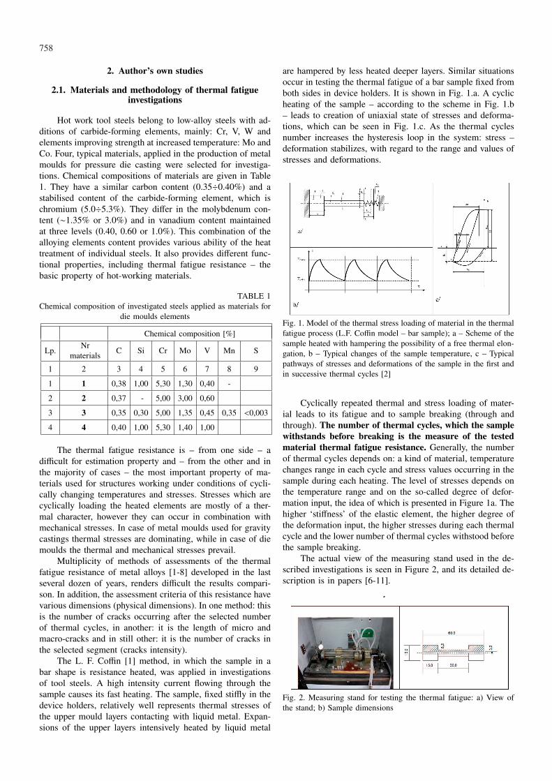
The actual view of the measuring stand used in the de-scribed investigations is seen in Figure 2, and its detailed de-scription is in papers [6-11].
Fig. 2. Measuring stand for testing the thermal fatigue: a) View ofthe stand; b) Sample dimensions

759
2.2. Results of investigations
The thermal fatigue resistance of four steels intended forhot working, which chemical compositions are given in Ta-ble 1, were measured. Investigations were carried out underconstant conditions of the so-called stiffness of the samplefixing system (constant degree of the deformation input). Theresistance of these materials was determined at the constantminimum temperature of the cycle (Tmin = 200◦C). Three val-ues of the maximum cycle temperature were applied (Tmax =
700; 725 and 750◦C). The lower temperature of the cyclecorresponds with the work temperature of metal moulds forthe majority of metal moulds, die moulds and gravity dies.The upper value of the cycle range, which is similar to themould heating range at casting copper or ferrous alloys, wasrather caused by limiting long-lasting experiments. The testedmaterials sustain, at the described above temperature ranges,a few thousands of cycles, which – when approximately halfa minute is needed for one cycle – means that the individualmeasurement lasts several dozen of hours.
The recorded pathways of temperature and stresses insuccessive thermal cycles are presented in Figures 3-5. Thecontrol thermo-couple, welded to the sample, allows to recordtemperature changes in the middle of the sample length, thatis in places where these changes are the largest. Stresses arecalculated on the basis of the constant stiffness of the sam-ple fixing system (schematically marked as a spring in Fig.1) and on the measured deformations (displacement of barends – seen in Fig. 2.a). This displacement is controlled in acontact-less way – by means of the laser sensor and the resultsare saved in computer in a real time.
Fig. 3. Typical pathways of sample temperature changes recorded inthermal fatigue investigations of alloyed steels, applied for die moulds
The analysis of the recorded pathways allows to notice ahigh stability in maintaining temperature ranges of the thermalcycles similar to those, which take place in the mould rhythmi-cally poured with liquid metal. Analysing the states of stress,it can be noticed that already the first cycle causes large plasticdeformations. Deformations are caused by the influence of ap-propriately large compressive stresses, exceeding yield pointsof the tested material. As the result of these deformations thesample shortening occurs, which – in turn – causes the tensilestresses occurrence during the sample cooling. In the furtherthermal fatigue process the tensile stresses dominate. They are
more disadvantageous for the material durability and becomethe basic reason of micro and macrocracks formation and ofthe material continuity gaps.
Fig. 4. Changes of thermal stresses in the sample subjected to thermalfatigue investigations (No. 4 steel, temperature range: Tmin = 200◦C,Tmax = 725◦C)
Fig. 5. Relationship between the instantaneous temperature of theheated (and cooled) sample and the thermal stresses occurring in it(No. 4 steel, temperature range: Tmin = 200◦C, Tmax = 725◦C)
The performed investigations of the thermal fatigue undersimilar thermal and stress conditions allowed to carry out thecomparative estimation of the selected alloyed steels, Fig. 6.Out of the examined group of materials the highest resistancecharacterises chromium – molybdenum – vanadium steel ofan increased content of vanadium and silicon (No. 4). A goodresistance has also steel of an increased content of silicon anda content of molybdenum and vanadium kept at a middle level.
The influence of the maximum cycle temperature on thealloyed steels thermal fatigue is similar to the one, which isobserved for several alloys applied for hot works. It can be de-scribed by an exponential equation, which causes that in thelogarithmic diagram points are in the straight line. It is shownin Figure 7. Describing the maximum temperature influenceby the regression equation allows to forecast the resistance ofthe investigated material (steel) under different conditions e.g.at lower or higher maximum temperatures of the cycle. This isimportant, since it enables to forecast the metal moulds dura-

760
bility on the grounds of knowing the temperature, to whichthe inner mould surface was heated.
Fig. 6. Thermal fatigue resistance of alloyed steels (Table 1), inves-tigations within the temperature range: Tmin = 200◦C, Tmax = 725◦C
Fig. 7. Typical character of the influence of the maximum temperatureof the thermal cycle on the steel thermal fatigue (on the example ofNo.1 steel)
2.3. Microstructure changes in the thermal fatigueprocess
Comparative investigations of the thermal fatigue resis-tance were performed for the alloyed steels without quench-ing and tempering (after soft annealing). Then, the structurewas built of alloyed ferrite and spheroidal carbide precipitates,mainly Cr and V carbides. The structure was tested in sam-ples which were previously subjected to a thermal fatigue. Thestructure was analysed in the zone of the highest heating ofsamples (their length middle) and in places which were notheavily warmed – in samples heads. In the zone of the max-imum sample temperature a grouping and growth of carbideprecipitates is observed as well as occurrence of oxides – seenas dark fields on polished sections. The ferritic matrix does notchange, in practice. The intensity of this structure rebuildingprocess is different for each investigated material. The largestchanges are observed in No. 1 steel, which contains the small-est amount of alloying elements: molybdenum and vanadium.Oxidizing processes always intensify the structure degradationand contribute to the micro-cracks development.
Generally, within the zone of the highest temperaturesand plastic deformations, the formation of clearly visible grainboundaries are seen. Processes of oxidation, movements of
structural defects and segregation of fine carbide precipitatesoccur more intensively on grain boundaries. An extensiveanalysis of structure transformations requires additional, inves-tigations – being currently under way – which will constitutethe separate paper.
TABLE 2Alloyed steel structure in the state of ‘after testing’ thermal fatigue
Nrsamples
Zone of the highesttemperatures – 725◦C
Zone not heavily warmed– in samples heads
1
2
3
4
3. Conclusions
Investigations of four steel grades for ‘hot working’, ap-plied as a material for die moulds elements indicate quite largedifferences in their thermal fatigue resistance. Those are steelscontaining 5.0% of Cr and variable contents of Mo, V andSi. The highest resistance characterises steel of an increasedcontent of vanadium (1.0%) and silicon (1.0%).
Cast steels of compositions given in Table 1 withstandfrom 2.000 to approximately 10.000 thermal cycles, at themaximum temperature of a cycle from the range: Tmax =
700÷750◦C.The influence of the maximum cycle temperature can be
described by the exponential equation (Fig. 7) and applyingthe developed equation the number of thermal cycles beforeoccurrence the macro-crack can be forecasted for other para-meters of the thermal cycle (lower or higher Tmax).
The thermal fatigue process at Tmax = 700÷750◦C leadsto microstructure changes, to accumulation of carbides ongrain boundaries and to matrix oxidations.

761
REFERENCES
[1] L.F C o f f i n, inni, Trans. Amer. Socjety of Mech. Engineers.TASMA. v. 76, 1954.
[2] P.A. D u l n i e w, P.I. K o t o w, Termiczeskaja ustałost mi-etałłow, Moskwa, Masinostrojenie (1980).
[3] A. W e r o ń s k i, Zmęczenie cieplne metali, WNT, Warszawa1983.
[4] R.B. G u n d l a c h, Giesserei -Praxis 4, 43-49 (1977).[5] K. R o h r i n g, Giesserei -Praxis 23, 375-392 (1978).[6] J. Z y c h, Zmęczenie cieplne żeliwa przeznaczonego na
formy metalowe, Prace Komisji Metal. Odlew. Metalurgia 38,107-116 (1988) PAN Katowice.
[7] J. Z y c h, The Impact of Some Selected Factors on CastIron Thermal Fatigue, Zeszyty Naukowe AGH, Metalurgia iOdlewnictwo, Tom 15, 1, 131-145 (1988).
[8] J. Z y c h, D. J ę d r z e j c z y k, Badania odporności nazmęczenie cieplne żeliwa z grafitem wermikularnym, PrzeglądOdlewnictwa 6, 215-218 (1991).
[9] J. Z y c h, Wpływ molibdenu na odporność na zmęczeniecieplne żeliwa szarego z grafitem płatkowym, wermikularnymi sferoidalnym, XX. Konf. Wydziału Odlewnictwa AGH, 93-99Kraków, 1995.
[10] J. Z y c h, Ocena odporności na zmęczenie cieplne żeli-wa szarego, wermikularnego i sferoidalnego, KonferencjaNaukowa z Okazji Dnia Odlewnika’ 96, Wydział OdlewnictwaAGH, 35-42, 21-22 listopad (1996).
[11] J. Z y c h, J. W r ó b e l, Influence of thermal fatigue of ductileiron GJS(Ni1,5MoCu) – base for producing ADI – on structureand tensile strength, Archives of Foundry Engineering; 2010vol. 10 spec. iss. 2 s. 177-181. Nogowizin B., Theorie undPraxis der Druckgusses; Schiele &Schon, Berlin 2011.
[12] E. H a b e r l i n g, K. R a s c h e, F. W e n d l, K.-D. W u p -p e r, Fortschrichtte und Entwicklungstendenzen auf dem Ge-biet der Werkzeugstahle, Thyssen Technische Berichte, Heft 1,93, 87-95.
[13] L. D o b r z a ń s k i, E. H a j d u c z e k, J. M a r c i n i a k, R.N o w o s i e l s k i, Metaloznawstwo i obróbka cieplna materi-ałów narzędziowych, WNT, Warszawa 1990.
Received: 15 February 2013.


![Analiza efektów zużywania się wybranych obręczy kół ... text.pdf2015/06/08 · zumianego tocznego zużywania zmęczeniowego, tzw. RCF (rolling contact fatigue) [2]. W literaturze](https://static.fdocuments.pl/doc/165x107/60d9767fa2770855f755ab33/analiza-efektw-zuywania-si-wybranych-obrczy-k-textpdf-20150608.jpg)