Textural properties of silica-based organic-inorganic ... · PDF fileMaterials Science-Poland,...
12
Materials Science-Poland, Vol. 23, No. 1, 2005 Textural properties of silica-based organic-inorganic polymer hybrid xerogels IWONA ZAR BA-GROD 1 , WLODZIMIERZ MI TA 2 , ANDRZEJ SIKORA 3 , TEODOR GOTSZALK 3 , WIESLAW STR K 2 , KRZYSZTOF HERMANOWICZ 2 , KRZYSZTOF MARUSZEWSKI 1* 1 Institute of Materials Science and Applied Mechanics, Wroclaw University of Technology, Smoluchowskiego 25, 50-370 Wroclaw, Poland 2 Institute for Low Temperature and Structure Research, Polish Academy of Sciences, Okólna 2, 50-950 Wroclaw, Poland 3 Laboratory of Near Field Microscopy, Nanometrics and Nanostructures, Wroclaw University of Technology, Janiszewskiego 11/17, 50-372 Wroclaw, Poland Samples of xerogels containing organic polymers were prepared by the sol-gel method via the reac- tion of tetraethoxysilane (TEOS) and organic monomers with an acidic catalyst. These materials were obtained as transparent and homogeneous bulk materials. The samples were characterized by Raman and IR spectroscopies, N 2 -adsorption (77 K), and atomic force microscopy (AFM). Specific surface areas and porosities of the samples were estimated from nitrogen adsorption-desorption isotherms at 77 K. Textural properties such as specific surface areas (S BET ), pore volume (V p ), average pore sizes (R p ), and micropore volume (V DR ) were obtained. The complete adsorption-desorption isotherms and pore size distributions were analysed following the Dollimore–Heal method. Atomic force microscopy was used to investigate the morphology and roughness of the samples. Key words: organic–inorganic polymer hybrid materials, sol-gel process, photo-polymerisation, organi- cally modified silicates, porosity, roughness 1. Introduction Organic-inorganic polymer hybrids are a new type of composite materials, in which the organic and inorganic components are combined at the molecular level [1]. There has been much research on the applications of these hybrid materials as func- tional coatings on glass, ITO (indium-tin oxide), and polymer substrates (bulks, pow- _________ * Corresponding author, e-mail: [email protected].
-
Upload
truongkien -
Category
Documents
-
view
213 -
download
0
Transcript of Textural properties of silica-based organic-inorganic ... · PDF fileMaterials Science-Poland,...

Materials Science-Poland, Vol. 23, No. 1, 2005
Textural properties of silica-based organic-inorganic polymer hybrid xerogels
IWONA ZARĘBA-GRODŹ1, WŁODZIMIERZ MIŚTA
2, ANDRZEJ SIKORA3,
TEODOR GOTSZALK3, WIESŁAW STRĘK
2, KRZYSZTOF HERMANOWICZ
2, KRZYSZTOF MARUSZEWSKI1*
1Institute of Materials Science and Applied Mechanics, Wrocław University of Technology, Smoluchowskiego 25, 50-370 Wrocław, Poland
2Institute for Low Temperature and Structure Research, Polish Academy of Sciences, Okólna 2, 50-950 Wrocław, Poland
3Laboratory of Near Field Microscopy, Nanometrics and Nanostructures, Wrocław University of Technology, Janiszewskiego 11/17, 50-372 Wrocław, Poland
Samples of xerogels containing organic polymers were prepared by the sol-gel method via the reac-tion of tetraethoxysilane (TEOS) and organic monomers with an acidic catalyst. These materials were obtained as transparent and homogeneous bulk materials. The samples were characterized by Raman and IR spectroscopies, N2-adsorption (77 K), and atomic force microscopy (AFM). Specific surface areas and porosities of the samples were estimated from nitrogen adsorption-desorption isotherms at 77 K. Textural properties such as specific surface areas (SBET), pore volume (Vp), average pore sizes (Rp), and micropore volume (VDR) were obtained. The complete adsorption-desorption isotherms and pore size distributions were analysed following the Dollimore–Heal method. Atomic force microscopy was used to investigate the morphology and roughness of the samples.
Key words: organic–inorganic polymer hybrid materials, sol-gel process, photo-polymerisation, organi-cally modified silicates, porosity, roughness
1. Introduction
Organic-inorganic polymer hybrids are a new type of composite materials, in which the organic and inorganic components are combined at the molecular level [1]. There has been much research on the applications of these hybrid materials as func-tional coatings on glass, ITO (indium-tin oxide), and polymer substrates (bulks, pow-_________
*Corresponding author, e-mail: [email protected].

I. ZARĘBA-GRODŹ et al. 148
ders, and fibres). In particular, these organic-inorganic polymer hybrids could poten-tially yield transparent, abrasion-resistant materials. They possess interesting proper-ties such as molecular homogeneity, transparency, flexibility, and durability. Such materials could be employed in various applications, e.g. solid state lasers (optical components), replacements for silicon dioxide as an insulating material in the micro-electronic industry, anti-corrosion coatings, scratch resistant coatings, contact lenses, host materials for chemical sensors, and membrane materials [2–7].
In these organic-inorganic polymer networks, formation of an inorganic network occurs through sol-gel processes [8]. The organic phase of the organic-inorganic polymer hybrid is synthesized “in situ” in liquid hydrolysed silica. The sol-gel method is widely used to prepare hybrid materials, since it has the advantage of being a low-temperature process and potentially giving highly homogeneous nanomaterials. The chemical reactions involved in the sol-gel process are as follows:
Si
Si
Si
OR
OH
OH
+
+
+
HOHhydrolysis
Si OH
Si OR
hydrolysis
alcoholysis
water condensation
alcohol condensation
Si OH + ROH
Si O Si + HOH
Si O Si + ROH
esterification
During these reactions, the hydrolysis and condensation of metal alkoxides (based on, e.g., Si, Ti, V, or Zr) such as tetraethoxysilane (TEOS) takes place and a network is formed in the process. During the build-up of the inorganic network, appropriately functionalised organic (or organic-inorganic) moieties can also be incorporated. This method can lead to either an alloy-like material (if a molecular dispersion is obtained) or a system with a morphology defined by the presence of several microphases [1].
Mechanical durability and reliability belong to the most important features of these materials. Thus, it is practically important to characterize and, if possible, con-trol and improve these properties. The relevant mechanical parameters are: hardness, elastic modulus, residual stress, fracture toughness, and interfacial fracture toughness (or adhesion energy) [9]. For certain materials it is also possible to measure such properties as surface roughness and porosity.
Surface roughness is of crucial importance for applications in many fields [10–12]. Multilayer coatings prepared from sol-gel films over polymeric substrates have found use in areas such as photography, radiography, holography, reprography (materials for printers and photocopiers), and optical or protective coatings [8]. Most of these materials must have a specific surface roughness in order to guarantee optimal adherence for retaining various active agents (e.g., inks) [13].
Organic-inorganic polymer hybrid xerogels
149
Porous materials with controlled porosity in the micropore (<2 nm) and mesopore (2–50 nm) ranges have received great attention due to their potential use as filters and sorbents in separation systems, catalytic supports in full cell electrodes, as well as double layer supercapacitors for energy storage. Numerous techniques for preparing micro- and mesoporous materials can be found in literature [14–18]. The preparation of micro- and mesoporous silica using organic agents as templates is a good example. By means of this technique, it is possible to obtain porous materials with large surface areas, high porosities, and controlled narrow pore size distributions (PSDs) in the micro-and mesopore ranges.
The preparation of these materials consists of three stages: (1) the infiltration of the porous structure of inorganic materials (templates) by organic components, (2) the polymerisation of the infiltrated materials, (3) the elimination of templates [19]. The procedure of core/template removal by calcinations was first introduced by Kawaha-shi and Mitijevi during their search to produce hollow spheres from yttrium com-pounds [20]. There exist many examples of templates employed in inorganic materi-als, which are usually SiO2, TiO2, or other common oxides. Synthetic polymers, surfactants, organogels, carbon nanotubes, or organic crystals and biomaterials have been used successfully as templates [21].
In this work, following our preliminary reports [22], we present hybrid organic -inorganic materials of the interpenetrated network (IPN) character. The relationships between the synthetic process and the textural properties of the sol-gel materials are discussed as well. The obtained materials have been investigated by spectroscopic (IR, Raman), microscopic (AFM), and nitrogen adsorption-desorption techniques.
2. Experimental
2.1. Synthesis
The syntheses of silica-based organic-inorganic polymer hybrid xerogels were car-ried out in ethanol solutions by combining the sol-gel [8] and organic photo-polymerisation [24] methods [22]. TEOS (tetraethoxysilane, Si(OC2H5)4, Sigma -Aldrich) was mixed with distilled water with hydrochloric acid (HClaq, Polish Chemi-cal Reagents) as a catalyst. The reagent molar ratio TEOS:H2O was 1:16. The solution was stirred for 1 hour at room temperature. The organic monomers, acrylamide (C3H5NO) or 2-hydroxy-ethylmethacrylate (C6H10O3, HEMA), and the photo-initiator, benzil (C14H10O2), were purchased from Sigma-Aldrich. The monomers and the initia-tor were introduced to the liquid hydrolysed silicate solutions. The molar ratios of the components are presented in Table 1. The compositions of silica/organic monomers were irradiated by UV light (a Hg lamp, OPTEL Opole, Poland) at room temperature for 5 h [24].

I. ZARĘBA-GRODŹ et al. 150
Table 1. Molar ratios of the components
Molar ratio No.
TEOS Acrylamide HEMA Benzil
1 1 – – – 2 1 – 0.3 0.0025 3 1 0.3 – 0.0025 4 1 0.15 0.15 0.0025
2.2. Characterisation
Raman spectra were measured on a Bruker RFS100/S FT-Raman spectrophotome-ter. IR spectra were measured on a FT IR Biorad FTS 575C spectrophotometer. The morphologies and structures of the materials were characterized by an Atomic Force Microscope (DME Rasterscope 3000). The roughness of the organic-inorganic poly-mer hybrid samples were calculated using the European/Polish Norm ISO 4287:1997 [25]. The roughness scaling characteristics were determined by statistical analysis of the AFM surface images using homemade scaling analysis software. The specific surface areas and porosities of the samples were obtained from nitrogen adsorption -desorption isotherms measured on a Sorptomatic 1900 FISONS system at 77 K. The samples were evacuated at 200 °C (using a rotary pump) in order to remove the liquid from the pores. The pore size distributions were analysed following the Dollimore –Heal method [26]. For microporous materials, the specific surface areas and micro-pore volumes (VDR) were calculated by the Dubinin method [27]. Pore volume (Vp) was calculated from the adsorbed volumes at p/p0 = 0.95. Pyrolysis of the organic -inorganic polymer hybrid samples was performed at 600 °C under oxygen flow (heat-ing rate = 5 °C/min). In order to remove residual water, alcohol and all organic com-ponents from the silica glass, the inorganic silica sol-gel polymers were heat-treated at 600 °C, 750 °C, 900 °C, or 1050 °C under oxygen flow (heating rate was 5 °C/1min). The porosities of all the organic-inorganic polymer hybrid samples and the inorganic silica polymer were also measured before and after calcinations.
3. Results and discusion
FT-IR and FT-Raman spectra of the SiO2/acrylamide polymer hybrid (a), the SiO2/HEMA polymer hybrid (b), and the SiO2/acrylamide–HEMA copolymer hybrid (c) are presented in Figs. 1 and 2, respectively. FT-IR and FT-Raman spectra (not shown) were obtained and compared for the pure SiO2 sample and the independently made organic polymers and copolymers as well as for the free organic monomers. The analysis of these spectra is described in [22].

Organic-inorganic polymer hybrid xerogels
151
Fig. 1. FT-IR spectra of SiO2/acrylamide polymer
hybrid (a), SiO2/HEMA polymer hybrid (b), and SiO2/acrylamide-HEMA copolymer hybrid (c)
Fig. 2. FT-Raman spectra of SiO2/acrylamide polymer hybrid (a), SiO2/HEMA polymer hybrid (b), and SiO2/acrylamide-HEMA copolymer hybrid (c)
The surface texture is defined as the local deviation of a surface from its ideal shape. The deviations may be repetitive or random and may result from roughness, waviness, lay, and defects. Roughness comes from the finer irregularities of the sur-face, usually including those that result from the inherent action of the production process [28, 29]. Porosity is defined as the ratio of the void space volume to the bulk volume of a sample (expressed as a fraction or percentage) [27].
AFM was used to measure the surface roughness of the organic-inorganic polymer hybrid samples. Parameters such as the roughness average (Ra), root mean square roughness (Rq), maximum profile peak height (Rp), maximum profile valley depth (Rv), and average maximum height of the profile (Rz), obtained from these images, are listed in Table 2. Ra and Rq are two of the most often used parameters concerning surface roughness [30, 31].
The average roughness Ra is defined as:
( )0
1L
aR Y x dxL
= ∫ (1)
where: Ra is the arithmetic average deviation from the mean line, L – the sampling length, Y – the ordinate of the profile curve.

I. ZARĘBA-GRODŹ et al. 152
Table 2. Roughness parameters
Name SiO2
/polyacrylamide SiO2
/polyHEMA
SiO2
/poly(acrylamide -co-HEMA)
Average roughness, Ra (nm) 0.707 4.002 4.442 Root mean square roughness, Rq (nm) 0.956 5.122 5.555 Maximum profile peak height, Rp (nm) 4.649 17.055 22.235 Maximum profile valley depth, Rv (nm) 3.335 14.858 13.329 Average maximum height of the profile, Rz (nm) 7.984 31.914 35.564 Percentage distribution of the height, P (%) 38.2 26.2 26.4 Material ratio of the profile Rmr[cr], (%) 100 100 100
Fig. 3. AFM image (a), height distribution profile of surface roughness (b), and Abbott–Firestone curve (bearing ratio analysis) (c) of a sample
silica/acrylamide polymer hybrid
The parameter Rq is defined as:
a) b)
c)
1,3 µm
1,3 µm
1,3 µm 6,9 µm
1,3 µm 0,0 µm

Organic-inorganic polymer hybrid xerogels
153
2
0
1( )
L
qR Y x dxL
= ∫ (2)
Rq is the root mean square average of the measured height deviations, taken within the evaluation length or area and measured from the mean linear surface. Rq represents the standard deviation of the profile heights and is used in the computation of skew and kurtosis.
Fig. 4. AFM image (a), height distribution profile of surface roughness (b), and Abbott-Firestone curve
(bearing ratio analysis) (c) of a sample silica/HEMA polymer hybrid
Figures 3a–5a show the topographies of synthetic organic-inorganic polymer hy-brids obtained by the sol-gel method. It can be seen that the AFM images of polysilica/polyHEMA and polysilica/poly(acrylamide-co-HEMA) are a little different from that of polysilica/polyacrylamide. The AFM pictures demonstrate that the crea-tion of polyacrylamide “in situ” in the silica matrix results in a surface less rough than that obtained by adding other organic polymers.
a) b)
c)
1,3 µm 1,3 µm
1,3 µm
1,3 µm
33,7 µm
0,0 µm

I. ZARĘBA-GRODŹ et al. 154
Figures 3b–5b show the height distribution profiles of surfaces roughness. The histograms of the surface height distribution profiles, obtained from AFM images, show that all of the organic-inorganic polymer hybrid samples have surfaces with irregularities of quite small height. In the cases of polysilica/polyHEMA and polysilica/poly(acrylamide-co-HEMA), the largest observed heights were 15 nm and 11 nm, respectively. The sample of polysilica/acrylamide displays an even smaller amplitude of the irregularities – 3,5 nm. This trend is also followed by the widths of irregularity height distribution peaks. The sample of polysilica/acrylamide displays a distribution peak much narrower than that of polysilica/polyHEMA and polysilica /poly(acrylamide-co-HEMA) samples.
Fig. 5. AFM image (a), height distribution profile of surface roughness (b), and Abbott-Firestone curve
(bearing ratio analysis) (c) of a sample sil-ica/acrylamide-HEMA copolymer hybrid
Figures 3c–5c show bearing ratio analyses. A bearing ratio analysis indicates the percentage of a surface that falls above/below a particular depth. The material ratio Rmr[cr] is the ratio expressed in percent of the material-filled length to the evaluation length lm at the profile section level c:
( )[ ] 1 21
... 100%mr cr nm
R L L Ll
= + + + × (3)
a) b)
c)
0,8 µm 0,8 µm
1,3 µm
35,1 µm
0,8 µm
0,0 µm
Organic-inorganic polymer hybrid xerogels
155
The material ratio curve (the Abbott–Firestone curve – AFC) shows Rmr[cr] as a function of the profile section level c. The Abbot–Firestone curve plays an impor-tant role in contact mechanics and wet friction applications. Based on Figs. 3c–5c, it has been found that about 50% of the material in each sample resides in medium-sized surface irregularities.
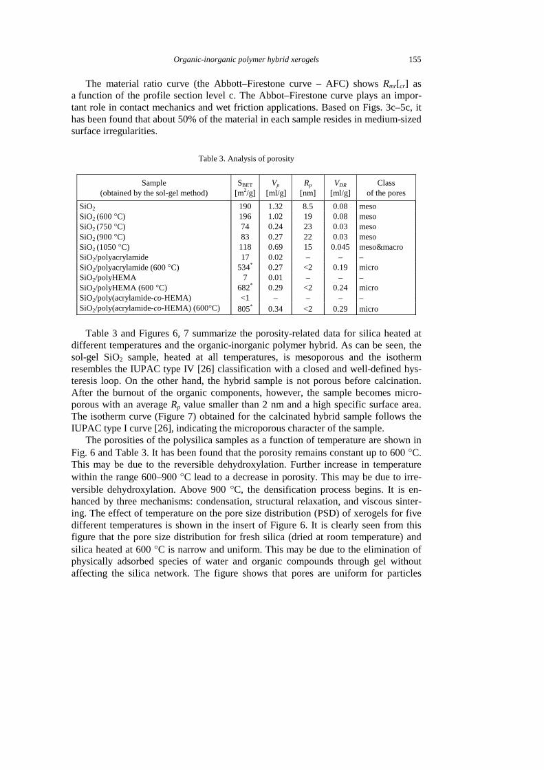
Table 3. Analysis of porosity
Sample (obtained by the sol-gel method)
SBET [m2/g]
Vp
[ml/g] Rp
[nm] VDR
[ml/g] Class
of the pores
SiO2 190 1.32 8.5 0.08 meso SiO2 (600 °C) 196 1.02 19 0.08 meso SiO2 (750 °C) 74 0.24 23 0.03 meso SiO2 (900 °C) 83 0.27 22 0.03 meso SiO2 (1050 °C) 118 0.69 15 0.045 meso¯o SiO2/polyacrylamide 17 0.02 – – – SiO2/polyacrylamide (600 °C) 534* 0.27 <2 0.19 micro SiO2/polyHEMA 7 0.01 – – – SiO2/polyHEMA (600 °C) 682* 0.29 <2 0.24 micro SiO2/poly(acrylamide-co-HEMA) <1 – – – – SiO2/poly(acrylamide-co-HEMA) (600°C) 805* 0.34 <2 0.29 micro
Table 3 and Figures 6, 7 summarize the porosity-related data for silica heated at
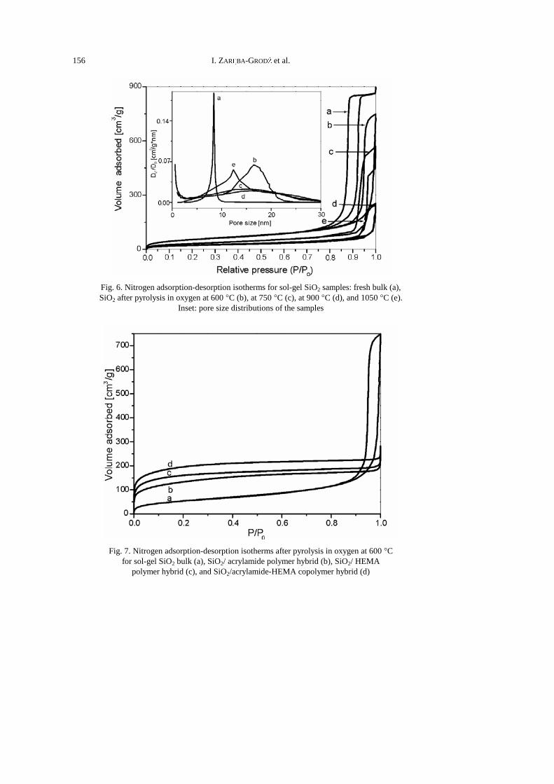
different temperatures and the organic-inorganic polymer hybrid. As can be seen, the sol-gel SiO2 sample, heated at all temperatures, is mesoporous and the isotherm resembles the IUPAC type IV [26] classification with a closed and well-defined hys-teresis loop. On the other hand, the hybrid sample is not porous before calcination. After the burnout of the organic components, however, the sample becomes micro-porous with an average Rp value smaller than 2 nm and a high specific surface area. The isotherm curve (Figure 7) obtained for the calcinated hybrid sample follows the IUPAC type I curve [26], indicating the microporous character of the sample.
The porosities of the polysilica samples as a function of temperature are shown in Fig. 6 and Table 3. It has been found that the porosity remains constant up to 600 °C. This may be due to the reversible dehydroxylation. Further increase in temperature within the range 600–900 °C lead to a decrease in porosity. This may be due to irre-versible dehydroxylation. Above 900 °C, the densification process begins. It is en-hanced by three mechanisms: condensation, structural relaxation, and viscous sinter-ing. The effect of temperature on the pore size distribution (PSD) of xerogels for five different temperatures is shown in the insert of Figure 6. It is clearly seen from this figure that the pore size distribution for fresh silica (dried at room temperature) and silica heated at 600 °C is narrow and uniform. This may be due to the elimination of physically adsorbed species of water and organic compounds through gel without affecting the silica network. The figure shows that pores are uniform for particles
I. ZARĘBA-GRODŹ et al. 156
Fig. 6. Nitrogen adsorption-desorption isotherms for sol-gel SiO2 samples: fresh bulk (a), SiO2 after pyrolysis in oxygen at 600 °C (b), at 750 °C (c), at 900 °C (d), and 1050 °C (e).
Inset: pore size distributions of the samples
Fig. 7. Nitrogen adsorption-desorption isotherms after pyrolysis in oxygen at 600 °C
for sol-gel SiO2 bulk (a), SiO2/ acrylamide polymer hybrid (b), SiO2/ HEMA polymer hybrid (c), and SiO2/acrylamide-HEMA copolymer hybrid (d)
Organic-inorganic polymer hybrid xerogels
157
heated at both temperatures. At medium temperatures (750 °C and 900 °C), the pore size distributions are wide and shifted towards larger pore sizes. At a higher tempera-ture (1050 °C), the PSD is uniform and narrow compared to the PSD at a lower tem-perature (600 °C). It is interesting to note that the narrow PSD at the higher tempera-ture is shifted towards smaller pore sizes. This is due to the formation of a continuous network, attributed to the condensation of the silanol groups and leading to a com-plete formation of Si–O–Si bonds. Heating xerogels above 1050 °C led to the forma-tion of a continuous SiO2 network without any porosity.
4. Conclusions
Organic-inorganic polymer hybrids were investigated by FT-IR, FT-Raman, AFM, and N2-adsorption (77K) methods. AFM micrographs of the organic-inorganic polymer hybrid samples show that the obtained materials are homogenous. Based on the AFM micrographs and the Polish Standards definitions [25], it has been established that the sample surfaces are randomly isotropic and do not exhibit periodicity or any other regu-larity. The height distribution profile of surface roughness indicates that the greatest contribution to roughness comes from profiles with medium heights. The pore size of the inorganic silica polymers can be controlled by varying the heating temperatures. The template method can be used to prepare microporous silica of various specific surface areas and pore sizes.
Acknowledgements
This work has been partially funded by the Polish State Committee for Scientific Research (grant KBN 3 T09 008 26).
References
[1] SPERLING L.H., Interpenetrating Polymer Networks and Related Materials, Plenum Press, New York, 1981, Ch. 1.
[2] JUDEINSTEIN P., SANCHEZ C., J. Mater. Chem., 6 (1996), 511. [3] MACKENZIE J.D., BESCHER E.P., J. Sol-Gel Sci. Tech., 13 (1998), 371. [4] KLUKOWSKA A., POSSET U., SCHOTTNER G., WIS M.L., SALEMI -DELVAUX C., MALATESTA V., Mat.
Sci., 20 (2001), 95. [5] GIGANT K., POSSET U., SCHOTTNER G., Appl. Spectr., 56 (2002), 762. [6] SANCHEZ C., LEBEAU B., CHAPUT F., BOILOT J-P., Adv. Mater., 15, (2003), 1969. [7] CASTELVETRO V., DE VITA C., Adv. Colloid Interface Sci., 108-109 (2004). [8] BRINKER C.J., SCHERER G.W., Sol-Gel Science, Academic Press, San Diego, 1990. [9] MALZBENDER J., DEN TOONDER J.M.J., BALKENENDE A.R., DE WITH G., Mater. Sci. Eng., R36 (2002), 47.
[10] HERMANN H., PITSCHE W., MATTERN N., Phys. Stat. Sol. (a) 132 (1992), 103. [11] SMITH P.F., CHUN I., LIU G., DIMITRIEVICH D., RASBURN J., VACSO G.J., Polym. Eng. Sci., 36 (1996), 2129. [12] CASTRO-RODRIGUEZ R., OLIVA A.I., SOSA V., CABALLERO-BRIONES F., PEÑA J.L., Appl. Surf. Sci.,
161 (2000), 340.
I. ZARĘBA-GRODŹ et al. 158
[13] LARENA A., MILLAN F., VERDU M., PINTO G., Appl. Surf. Sci. 174 (2001), 217. [14] FUERTES A.B., Mater. Lett. 58 (2004), 1494. [15] WANG X., LI W., ZHU G., QIU S., ZHAO D., ZHONG B., Microporous and Mesoporous Mater., 71
(2004), 87. [16] ALVAREZ S., FUERTES A.B., Carbon, 42 (2004), 423. [17] CHOMA J., KLOSKE M., JARONIEC M., J. Colloid Interface Sci., 266 (2003), 168. [18] OGAWA M., J. Photochem. Photobiol., C: Photochem. Rew., 3 (2002), 129. [19] FUERTES A.B., NEVSKAIA D.M., Microporous and Mesoporous Mater., 62 (2003), 177. [20] KAWAHASHI N., MATIJEVIĆ E., J. Colloid Interface Sci., 143 (1991), 103. [21] KJELD VAN BOMMEL J.C., FRIGGERI A., SHINKAI S., Angew. Chem. Int. Ed., 9 (2003), 42. [22] ZARĘBA-GRODŹ I., MIŚTA W., STRĘK W., BUKOWSKA E., HERMANOWICZ K., MARUSZEWSKI K., Opt.
Mater., 26 (2004), 207. [23] NOVIKOVA E., KOLENDO A., SYROMYATNIKOV V., AVRAMENKO L., PROT T., GOLEC K., Polimery 46
(2001), 6 (in Polish). [24] MATSUURA Y., MATSUKAWA K., KAWABATA R., HIGASHI N., NIWA M., INOUE H., Polymer, 43 (2002),
1549. [25] Polish Norm ISO 4287:1998. [26] SING K.S. (Ed.), Pure & Appl. Chem., 57, (1985), 603. [27] GREGG S.J., SING K.S.W., Adsorption, Surface Area and Porosity, Academic Press, second Ed.,
London, 1982. [28] LOU M.S., CHEN J.C., LI C.M., J. Ind. Technolog., 15 (1999), No. 1. [29] SUNG J.N., HU Y., FRIEZE W.E., CHEN W., GIDLEY D.W., J. Electrochem. Soc., 150 (2003), F97–F101. [30] YANG J.L., CHEN J.C., J. Ind. Technolog., 17 (1999), No. 2. [31] OCZOŚ K.E., LIUBIMOV V., Geometrical surface structure, OWPRz, Rzeszów, 2003 (in Polish).
Received 20 October 2004 Revised 8 December 2004