PN 1200-5.1 D-GB/F/I/ESP/RUS
11
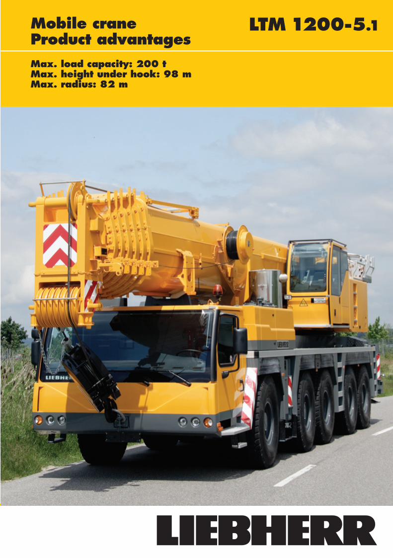
LTM 1200-5.1 Mobile crane Product advantages Max. load capacity: 200 t Max. height under hook: 98 m Max. radius: 82 m
Transcript of PN 1200-5.1 D-GB/F/I/ESP/RUS
PN 1200-5.1_D-GB/F/I/ESP/RUS 03.07.2007 10:09 Uhr Seite 1
Probedruck
C M Y CM MY CY CMY K
Liebherr-Werk Ehingen GmbHPostfach 1361, D-89582 Ehingen� +49 7391 5 02-0, Fax +49 7391 5 02-33 99www.liebherr.com, E-Mail: [email protected]
LTM 1200-5.1Mobile craneProduct advantagesMax. load capacity: 200 tMax. height under hook: 98 mMax. radius: 82 m
Subject to modifications. PN 155.01.E07.2007
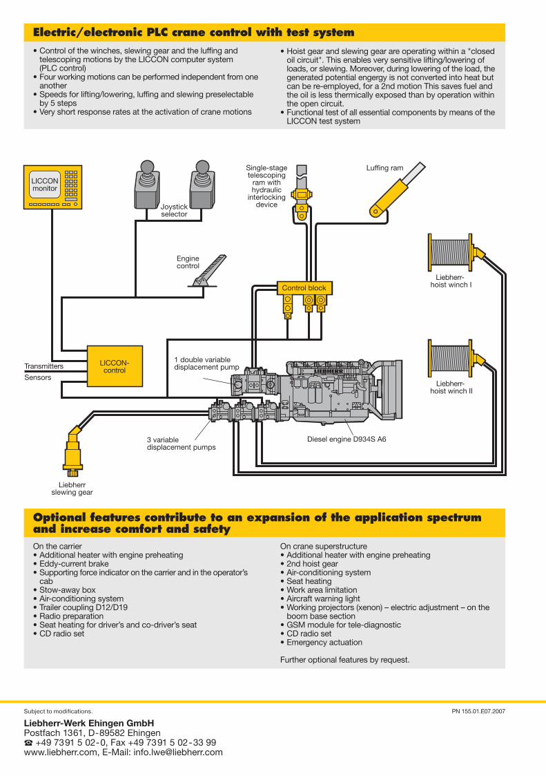
Electric/electronic PLC crane control with test system• Control of the winches, slewing gear and the luffing and
telescoping motions by the LICCON computer system(PLC control)
• Four working motions can be performed independent from oneanother
• Speeds for lifting/lowering, luffing and slewing preselectableby 5 steps
• Very short response rates at the activation of crane motions
• Hoist gear and slewing gear are operating within a "closedoil circuit". This enables very sensitive lifting/lowering ofloads, or slewing. Moreover, during lowering of the load, thegenerated potential engergy is not converted into heat butcan be re-employed, for a 2nd motion This saves fuel andthe oil is less thermically exposed than by operation withinthe open circuit.
• Functional test of all essential components by means of theLICCON test system
On the carrier• Additional heater with engine preheating• Eddy-current brake• Supporting force indicator on the carrier and in the operator’s
cab• Stow-away box• Air-conditioning system• Trailer coupling D12/D19• Radio preparation• Seat heating for driver’s and co-driver’s seat• CD radio set
On crane superstructure• Additional heater with engine preheating• 2nd hoist gear• Air-conditioning system• Seat heating• Work area limitation• Aircraft warning light• Working projectors (xenon) – electric adjustment – on the
boom base section• GSM module for tele-diagnostic• CD radio set• Emergency actuation
Further optional features by request.
Optional features contribute to an expansion of the application spectrumand increase comfort and safety
Luffing ram
Liebherr- hoist winch I
Single-stagetelescoping
ram withhydraulic
interlockingdeviceJoystick
selector
Enginecontrol
Control block
LICCONmonitor
3 variabledisplacement pumps
Diesel engine D934S A6
Transmitters1 double variabledisplacement pump
SensorsLiebherr-
hoist winch II
LICCON-control
Liebherrslewing gear
PN 1200-5.1_D-GB/F/I/ESP/RUS 03.07.2007 10:09 Uhr Seite 2
Probedruck
C M Y CM MY CY CMY K
112 LTM 1200-5.1 LTM 1200-5.1
4000
13298
15282
60
386550348899
34835396
R = 5450
R = 11010R = 11850
5500
6230
8300R = 4850 3000
20° 17°
12 t 12 t 12 t 12 t 12 t16.00 R 25
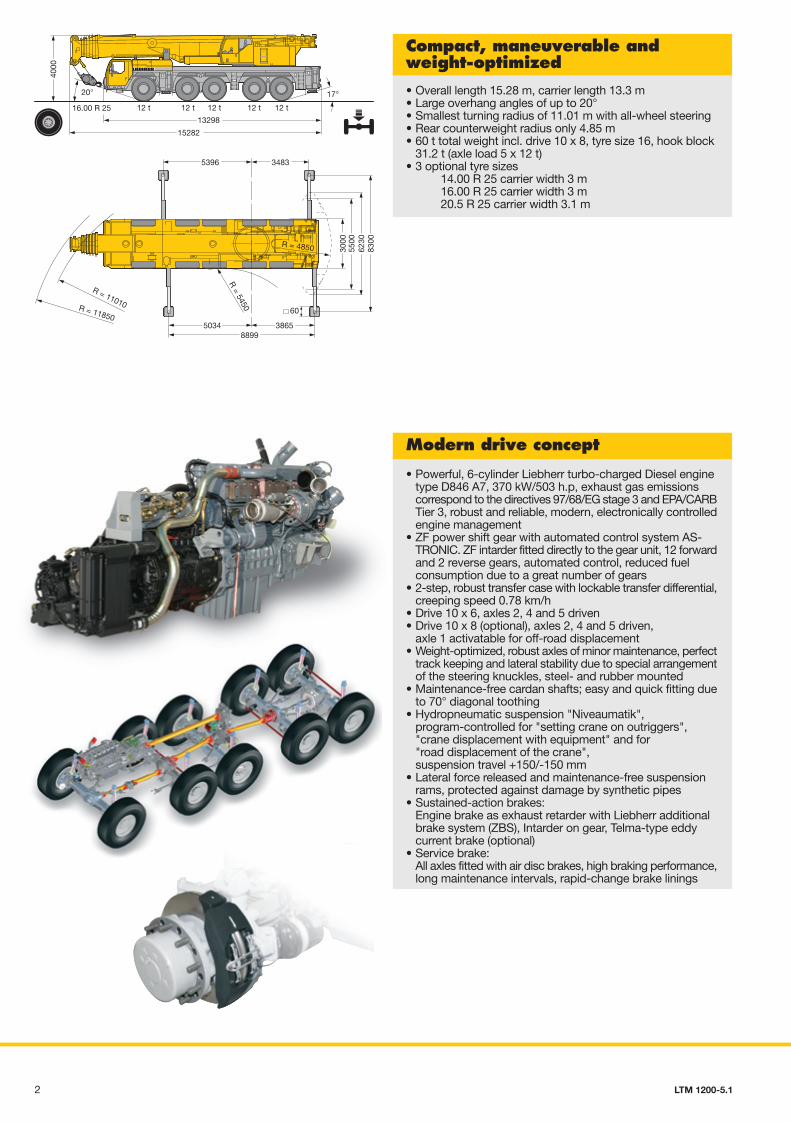
Compact, maneuverable andweight-optimized
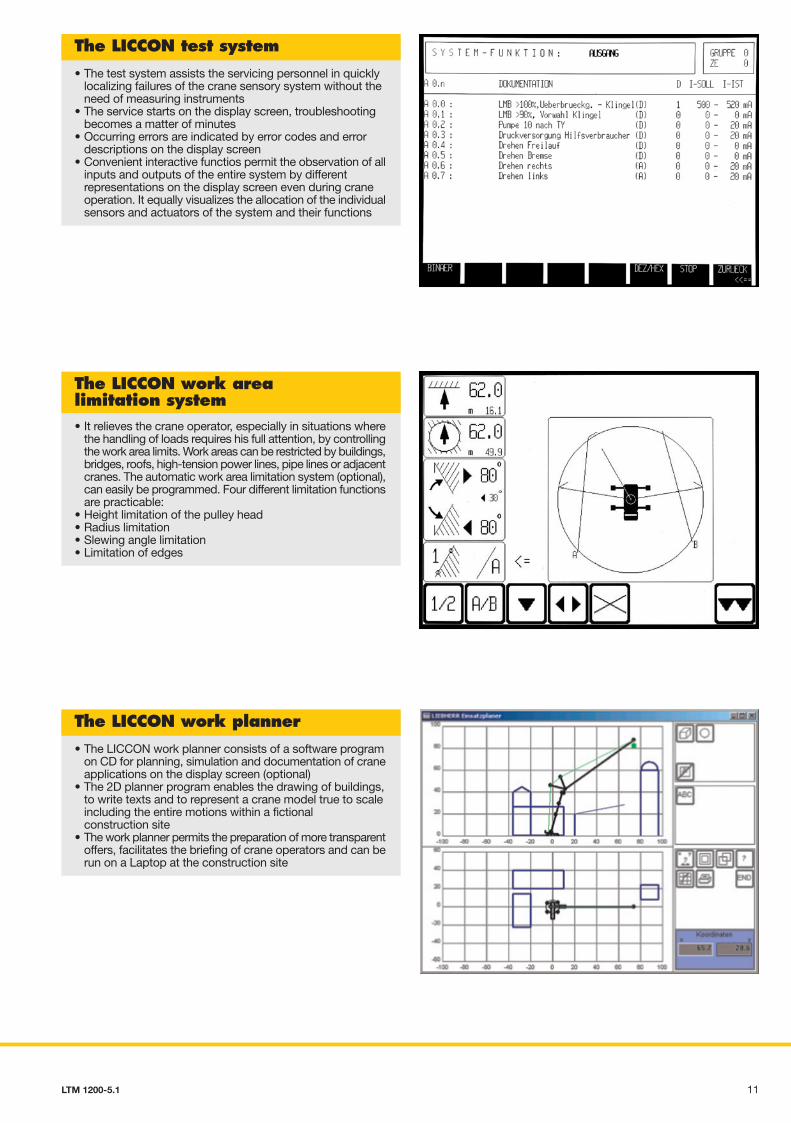
The LICCON test system
• The test system assists the servicing personnel in quicklylocalizing failures of the crane sensory system without theneed of measuring instruments
• The service starts on the display screen, troubleshootingbecomes a matter of minutes
• Occurring errors are indicated by error codes and errordescriptions on the display screen
• Convenient interactive functios permit the observation of allinputs and outputs of the entire system by differentrepresentations on the display screen even during craneoperation. It equally visualizes the allocation of the individualsensors and actuators of the system and their functions
The LICCON work arealimitation system• It relieves the crane operator, especially in situations where
the handling of loads requires his full attention, by controllingthe work area limits. Work areas can be restricted by buildings,bridges, roofs, high-tension power lines, pipe lines or adjacentcranes. The automatic work area limitation system (optional),can easily be programmed. Four different limitation functionsare practicable:
• Height limitation of the pulley head• Radius limitation• Slewing angle limitation• Limitation of edges
The LICCON work planner
• The LICCON work planner consists of a software programon CD for planning, simulation and documentation of craneapplications on the display screen (optional)
• The 2D planner program enables the drawing of buildings,to write texts and to represent a crane model true to scaleincluding the entire motions within a fictionalconstruction site
• The work planner permits the preparation of more transparentoffers, facilitates the briefing of crane operators and can berun on a Laptop at the construction site
• Powerful, 6-cylinder Liebherr turbo-charged Diesel enginetype D846 A7, 370 kW/503 h.p, exhaust gas emissionscorrespond to the directives 97/68/EG stage 3 and EPA/CARBTier 3, robust and reliable, modern, electronically controlledengine management
• ZF power shift gear with automated control system AS-TRONIC. ZF intarder fitted directly to the gear unit, 12 forwardand 2 reverse gears, automated control, reduced fuelconsumption due to a great number of gears
• 2-step, robust transfer case with lockable transfer differential,creeping speed 0.78 km/h
• Drive 10 x 6, axles 2, 4 and 5 driven• Drive 10 x 8 (optional), axles 2, 4 and 5 driven,
axle 1 activatable for off-road displacement• Weight-optimized, robust axles of minor maintenance, perfect
track keeping and lateral stability due to special arrangementof the steering knuckles, steel- and rubber mounted
• Maintenance-free cardan shafts; easy and quick fitting dueto 70° diagonal toothing
• Hydropneumatic suspension "Niveaumatik",program-controlled for "setting crane on outriggers","crane displacement with equipment" and for"road displacement of the crane",suspension travel +150/-150 mm
• Lateral force released and maintenance-free suspensionrams, protected against damage by synthetic pipes
• Sustained-action brakes:Engine brake as exhaust retarder with Liebherr additionalbrake system (ZBS), Intarder on gear, Telma-type eddycurrent brake (optional)
• Service brake:All axles fitted with air disc brakes, high braking performance,long maintenance intervals, rapid-change brake linings
Modern drive concept
• Overall length 15.28 m, carrier length 13.3 m• Large overhang angles of up to 20°• Smallest turning radius of 11.01 m with all-wheel steering• Rear counterweight radius only 4.85 m• 60 t total weight incl. drive 10 x 8, tyre size 16, hook block
31.2 t (axle load 5 x 12 t)• 3 optional tyre sizes
14.00 R 25 carrier width 3 m16.00 R 25 carrier width 3 m20.5 R 25 carrier width 3.1 m
PN 1200-5.1_D-GB/F/I/ESP/RUS 03.07.2007 10:09 Uhr Seite 3
Probedruck
C M Y CM MY CY CMY K
310 LTM 1200-5.1 LTM 1200-5.1
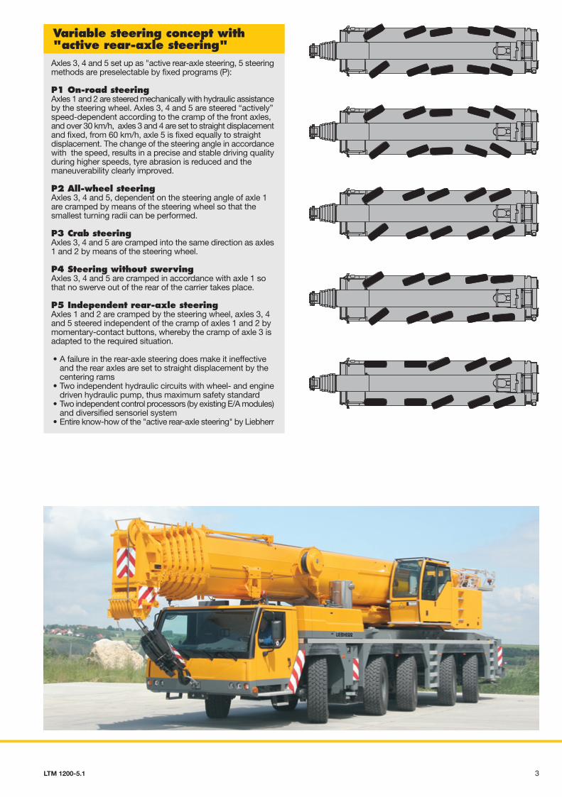
Axles 3, 4 and 5 set up as "active rear-axle steering, 5 steeringmethods are preselectable by fixed programs (P):
P1 On-road steeringAxles 1 and 2 are steered mechanically with hydraulic assistanceby the steering wheel. Axles 3, 4 and 5 are steered “actively”speed-dependent according to the cramp of the front axles,and over 30 km/h, axles 3 and 4 are set to straight displacementand fixed, from 60 km/h, axle 5 is fixed equally to straightdisplacement. The change of the steering angle in accordancewith the speed, results in a precise and stable driving qualityduring higher speeds, tyre abrasion is reduced and themaneuverability clearly improved.
P2 All-wheel steeringAxles 3, 4 and 5, dependent on the steering angle of axle 1are cramped by means of the steering wheel so that thesmallest turning radii can be performed.
P3 Crab steeringAxles 3, 4 and 5 are cramped into the same direction as axles1 and 2 by means of the steering wheel.
P4 Steering without swervingAxles 3, 4 and 5 are cramped in accordance with axle 1 sothat no swerve out of the rear of the carrier takes place.
P5 Independent rear-axle steeringAxles 1 and 2 are cramped by the steering wheel, axles 3, 4and 5 steered independent of the cramp of axles 1 and 2 bymomentary-contact buttons, whereby the cramp of axle 3 isadapted to the required situation.
• A failure in the rear-axle steering does make it ineffectiveand the rear axles are set to straight displacement by thecentering rams
• Two independent hydraulic circuits with wheel- and enginedriven hydraulic pump, thus maximum safety standard
• Two independent control processors (by existing E/A modules)and diversified sensoriel system
• Entire know-how of the "active rear-axle steering" by Liebherr
Variable steering concept with"active rear-axle steering"
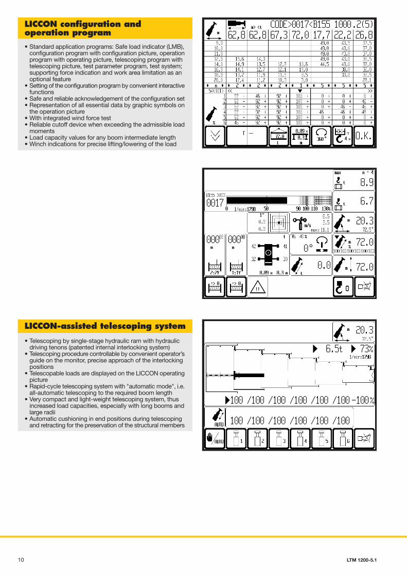
• Standard application programs: Safe load indicator (LMB),configuration program with configuration picture, operationprogram with operating picture, telescoping program withtelescoping picture, test parameter program, test system;supporting force indication and work area limitation as anoptional feature
• Setting of the configuration program by convenient interactivefunctions
• Safe and reliable acknowledgement of the configuration set• Representation of all essential data by graphic symbols on
the operation picture• With integrated wind force test• Reliable cutoff device when exceeding the admissible load
moments• Load capacity values for any boom intermediate length• Winch indications for precise lifting/lowering of the load
LICCON configuration andoperation program
• Telescoping by single-stage hydraulic ram with hydraulicdriving tenons (patented internal interlocking system)
• Telescoping procedure controllable by convenient operator’sguide on the monitor, precise approach of the interlockingpositions
• Telescopable loads are displayed on the LICCON operatingpicture
• Rapid-cycle telescoping system with "automatic mode", i.e.all-automatic telescoping to the required boom length
• Very compact and light-weight telescoping system, thusincreased load capacities, especially with long booms andlarge radii
• Automatic cushioning in end positions during telescopingand retracting for the preservation of the structural members
LICCON-assisted telescoping system
PN 1200-5.1_D-GB/F/I/ESP/RUS 03.07.2007 10:09 Uhr Seite 4
Probedruck
C M Y CM MY CY CMY K
94 LTM 1200-5.1 LTM 1200-5.1
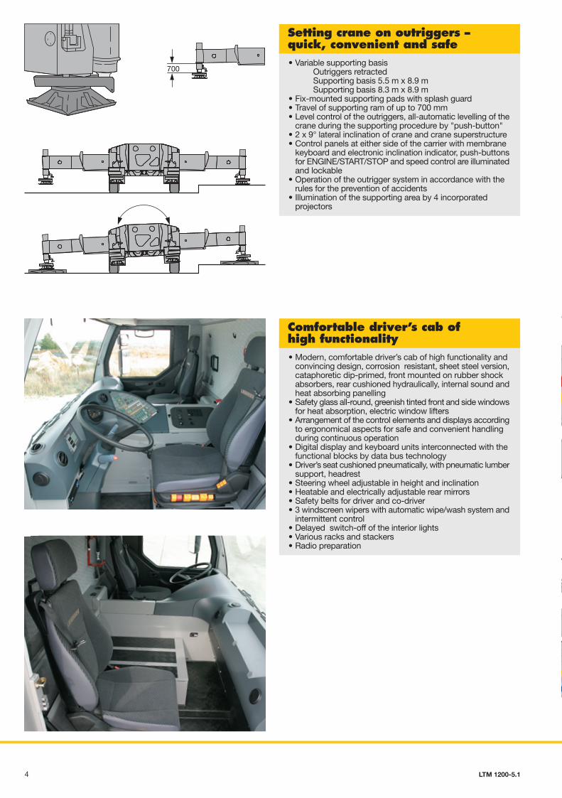
700
LSB -LSB -LSB -CAN -SCI -
• Variable supporting basisOutriggers retractedSupporting basis 5.5 m x 8.9 mSupporting basis 8.3 m x 8.9 m
• Fix-mounted supporting pads with splash guard• Travel of supporting ram of up to 700 mm• Level control of the outriggers, all-automatic levelling of the
crane during the supporting procedure by "push-button"• 2 x 9° lateral inclination of crane and crane superstructure• Control panels at either side of the carrier with membrane
keyboard and electronic inclination indicator, push-buttonsfor ENGINE/START/STOP and speed control are illuminatedand lockable
• Operation of the outrigger system in accordance with therules for the prevention of accidents
• Illumination of the supporting area by 4 incorporatedprojectors
Setting crane on outriggers –quick, convenient and safe
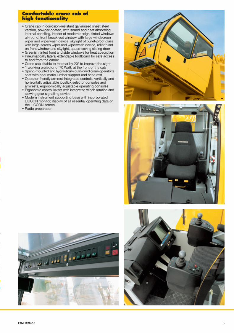
• Modern, comfortable driver’s cab of high functionality andconvincing design, corrosion resistant, sheet steel version,cataphoretic dip-primed, front mounted on rubber shockabsorbers, rear cushioned hydraulically, internal sound andheat absorbing panelling
• Safety glass all-round, greenish tinted front and side windowsfor heat absorption, electric window lifters
• Arrangement of the control elements and displays accordingto ergonomical aspects for safe and convenient handlingduring continuous operation
• Digital display and keyboard units interconnected with thefunctional blocks by data bus technology
• Driver’s seat cushioned pneumatically, with pneumatic lumbersupport, headrest
• Steering wheel adjustable in height and inclination• Heatable and electrically adjustable rear mirrors• Safety belts for driver and co-driver• 3 windscreen wipers with automatic wipe/wash system and
intermittent control• Delayed switch-off of the interior lights• Various racks and stackers• Radio preparation
Comfortable driver’s cab ofhigh functionality
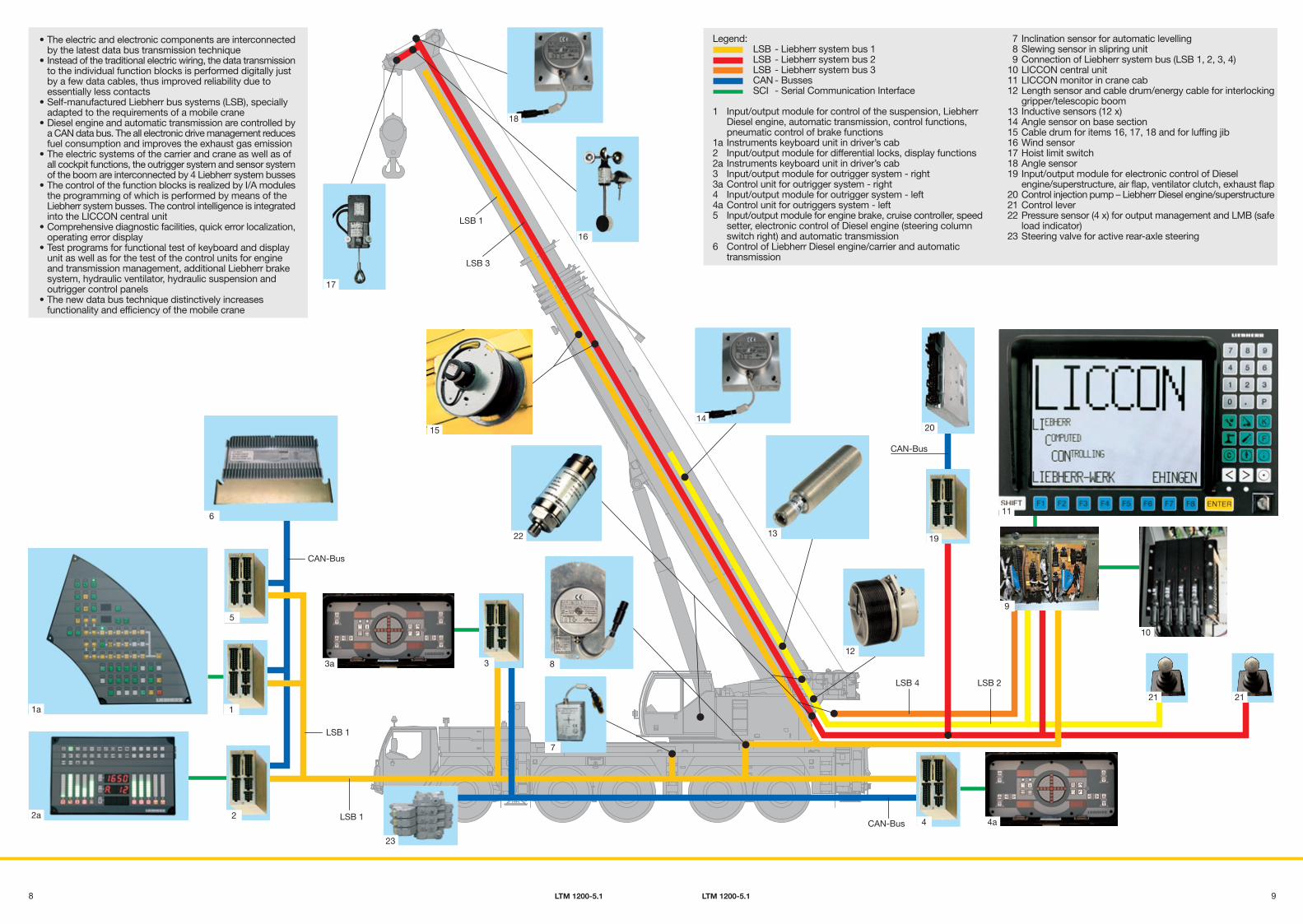
Legend:LSB - Liebherr system bus 1LSB - Liebherr system bus 2LSB - Liebherr system bus 3CAN - BussesSCI - Serial Communication Interface
1 Input/output module for control of the suspension, LiebherrDiesel engine, automatic transmission, control functions,pneumatic control of brake functions
1a Instruments keyboard unit in driver’s cab2 Input/output module for differential locks, display functions2a Instruments keyboard unit in driver’s cab3 Input/output module for outrigger system - right3a Control unit for outrigger system - right4 Input/output module for outrigger system - left4a Control unit for outriggers system - left5 Input/output module for engine brake, cruise controller, speed
setter, electronic control of Diesel engine (steering columnswitch right) and automatic transmission
6 Control of Liebherr Diesel engine/carrier and automatictransmission
7 Inclination sensor for automatic levelling 8 Slewing sensor in slipring unit 9 Connection of Liebherr system bus (LSB 1, 2, 3, 4)10 LICCON central unit11 LICCON monitor in crane cab12 Length sensor and cable drum/energy cable for interlocking
gripper/telescopic boom13 Inductive sensors (12 x)14 Angle sensor on base section15 Cable drum for items 16, 17, 18 and for luffing jib16 Wind sensor17 Hoist limit switch18 Angle sensor19 Input/output module for electronic control of Diesel
engine/superstructure, air flap, ventilator clutch, exhaust flap20 Control injection pump – Liebherr Diesel engine/superstructure21 Control lever22 Pressure sensor (4 x) for output management and LMB (safe
load indicator)23 Steering valve for active rear-axle steering
LSB 2
CAN-Bus
9
20
2121
12
14
19
11
10
13
4CAN-Bus
LSB 4
4a
PN 1200-5.1_D-GB/F/I/ESP/RUS 03.07.2007 10:09 Uhr Seite 5
Probedruck
C M Y CM MY CY CMY K
58 LTM 1200-5.1 LTM 1200-5.1
• Crane cab in corrosion-resistant galvanized sheet steelversion, powder-coated, with sound and heat absorbinginternal panelling, interior of modern design, tinted windowsall-round, front knock-out window with large windscreenwiper and wipe/wash device, skylight of bullet-proof glasswith large screen wiper and wipe/wash device, roller blindon front window and skylight, space-saving sliding door
• Greenish tinted front and side windows for heat absorption• Pneumatically lateral extendable footboard for safe access
to and from the carrier• Crane cab tiltable to the rear by 20° to improve the sight• 1 working projector of 70 Watt, at the front of the cab• Spring-mounted and hydraulically cushioned crane operator’s
seat with pneumatic lumber support and head rest• Operator-friendly armrest-integrated controls, vertically and
horizontally adjustable joystick selector consoles andarmrests, ergonomically adjustable operating consoles
• Ergonomic control levers with integrated winch rotation andslewing gear signalling device
• Modern instrument supporting base with incorporatedLICCON monitor, display of all essential operating data onthe LICCON screen
• Radio preparation
Comfortable crane cab ofhigh functionality
• The electric and electronic components are interconnectedby the latest data bus transmission technique
• Instead of the traditional electric wiring, the data transmissionto the individual function blocks is performed digitally justby a few data cables, thus improved reliability due toessentially less contacts
• Self-manufactured Liebherr bus systems (LSB), speciallyadapted to the requirements of a mobile crane
• Diesel engine and automatic transmission are controlled bya CAN data bus. The all electronic drive management reducesfuel consumption and improves the exhaust gas emission
• The electric systems of the carrier and crane as well as ofall cockpit functions, the outrigger system and sensor systemof the boom are interconnected by 4 Liebherr system busses
• The control of the function blocks is realized by I/A modulesthe programming of which is performed by means of theLiebherr system busses. The control intelligence is integratedinto the LICCON central unit
• Comprehensive diagnostic facilities, quick error localization,operating error display
• Test programs for functional test of keyboard and displayunit as well as for the test of the control units for engineand transmission management, additional Liebherr brakesystem, hydraulic ventilator, hydraulic suspension andoutrigger control panels
• The new data bus technique distinctively increasesfunctionality and efficiency of the mobile crane
LSB 3
LSB 1
CAN-Bus
3a 8
1
22a
1a
22
LSB 1
15
6
5
LSB 1
18
16
17
7
23
3
PN 1200-5.1_D-GB/F/I/ESP/RUS 03.07.2007 10:09 Uhr Seite 6
Probedruck
C M Y CM MY CY CMY K
76 LTM 1200-5.1 LTM 1200-5.1
80 m
70 m
60 m
50 m
40 m
30 m
20 m
10 m
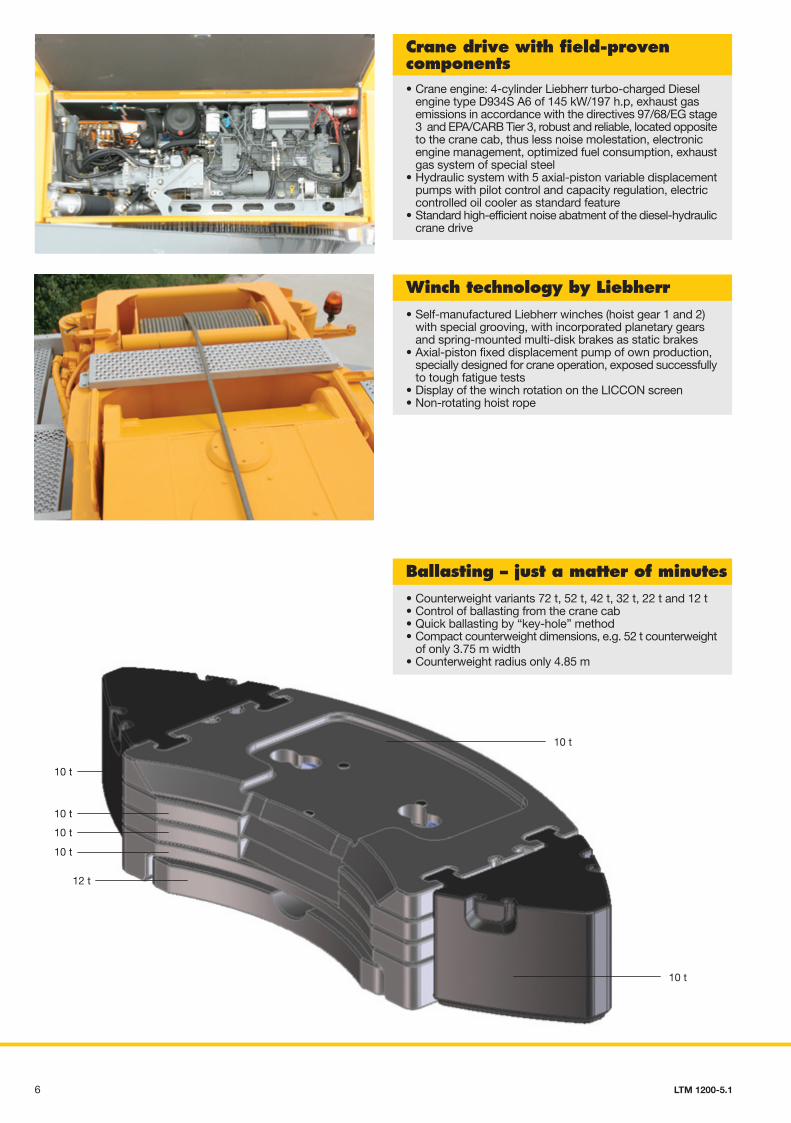
• Crane engine: 4-cylinder Liebherr turbo-charged Dieselengine type D934S A6 of 145 kW/197 h.p, exhaust gasemissions in accordance with the directives 97/68/EG stage3 and EPA/CARB Tier 3, robust and reliable, located oppositeto the crane cab, thus less noise molestation, electronicengine management, optimized fuel consumption, exhaustgas system of special steel
• Hydraulic system with 5 axial-piston variable displacementpumps with pilot control and capacity regulation, electriccontrolled oil cooler as standard feature
• Standard high-efficient noise abatment of the diesel-hydrauliccrane drive
Crane drive with field-provencomponents
• Self-manufactured Liebherr winches (hoist gear 1 and 2)with special grooving, with incorporated planetary gearsand spring-mounted multi-disk brakes as static brakes
• Axial-piston fixed displacement pump of own production,specially designed for crane operation, exposed successfullyto tough fatigue tests
• Display of the winch rotation on the LICCON screen• Non-rotating hoist rope
Winch technology by Liebherr
• Counterweight variants 72 t, 52 t, 42 t, 32 t, 22 t and 12 t• Control of ballasting from the crane cab• Quick ballasting by “key-hole” method• Compact counterweight dimensions, e.g. 52 t counterweight
of only 3.75 m width• Counterweight radius only 4.85 m
Ballasting – just a matter of minutes
10 t
10 t
10 t
10 t
10 t
12 t
10 t
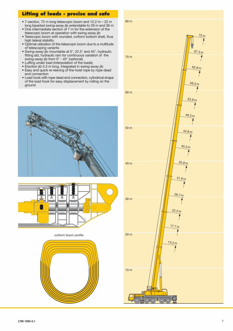
oviform boom profile
• 7-section, 72 m long telescopic boom and 12.2 m – 22 mlong biparted swing-away jib extendable to 29 m and 36 m
• One intermediate section of 7 m for the extension of thetelescopic boom at operation with swing-away jib
• Telescopic boom with rounded, oviform bottom shell, thushigh lateral stability
• Optimal utilization of the telescopic boom due to a multitudeof telescoping variants
• Swing-away jib mountable at 0°, 22.5° and 45°, hydraulicfitting aid, hydraulic ram for continuous variation of theswing-away jib from 0° - 45° (optional)
• Luffing under load (interpolation of the loads)• Erection jib 5.3 m long, integrated in swing-away jib• Easy and quick re-reeving of the hoist rope by rope dead
end connection• Load hook with rope dead end connection, cylindrical shape
of the load hook for easy displacement by rolling on theground
Lifting of loads - precise and safe
13.2 m
22.2 m
17.7 m
35.8 m
31.8 m
26.7 m
49.3 m
44.8 m
40.3 m
62.8 m
58.3 m
53.8 m
72 m
67.3 m
PN 1200-5.1_D-GB/F/I/ESP/RUS 03.07.2007 10:09 Uhr Seite 6
Probedruck
C M Y CM MY CY CMY K
76 LTM 1200-5.1 LTM 1200-5.1
80 m
70 m
60 m
50 m
40 m
30 m
20 m
10 m
• Crane engine: 4-cylinder Liebherr turbo-charged Dieselengine type D934S A6 of 145 kW/197 h.p, exhaust gasemissions in accordance with the directives 97/68/EG stage3 and EPA/CARB Tier 3, robust and reliable, located oppositeto the crane cab, thus less noise molestation, electronicengine management, optimized fuel consumption, exhaustgas system of special steel
• Hydraulic system with 5 axial-piston variable displacementpumps with pilot control and capacity regulation, electriccontrolled oil cooler as standard feature
• Standard high-efficient noise abatment of the diesel-hydrauliccrane drive
Crane drive with field-provencomponents
• Self-manufactured Liebherr winches (hoist gear 1 and 2)with special grooving, with incorporated planetary gearsand spring-mounted multi-disk brakes as static brakes
• Axial-piston fixed displacement pump of own production,specially designed for crane operation, exposed successfullyto tough fatigue tests
• Display of the winch rotation on the LICCON screen• Non-rotating hoist rope
Winch technology by Liebherr
• Counterweight variants 72 t, 52 t, 42 t, 32 t, 22 t and 12 t• Control of ballasting from the crane cab• Quick ballasting by “key-hole” method• Compact counterweight dimensions, e.g. 52 t counterweight
of only 3.75 m width• Counterweight radius only 4.85 m
Ballasting – just a matter of minutes
10 t
10 t
10 t
10 t
10 t
12 t
10 t
oviform boom profile
• 7-section, 72 m long telescopic boom and 12.2 m – 22 mlong biparted swing-away jib extendable to 29 m and 36 m
• One intermediate section of 7 m for the extension of thetelescopic boom at operation with swing-away jib
• Telescopic boom with rounded, oviform bottom shell, thushigh lateral stability
• Optimal utilization of the telescopic boom due to a multitudeof telescoping variants
• Swing-away jib mountable at 0°, 22.5° and 45°, hydraulicfitting aid, hydraulic ram for continuous variation of theswing-away jib from 0° - 45° (optional)
• Luffing under load (interpolation of the loads)• Erection jib 5.3 m long, integrated in swing-away jib• Easy and quick re-reeving of the hoist rope by rope dead
end connection• Load hook with rope dead end connection, cylindrical shape
of the load hook for easy displacement by rolling on theground
Lifting of loads - precise and safe
13.2 m
22.2 m
17.7 m
35.8 m
31.8 m
26.7 m
49.3 m
44.8 m
40.3 m
62.8 m
58.3 m
53.8 m
72 m
67.3 m
PN 1200-5.1_D-GB/F/I/ESP/RUS 04.07.2007 11:23 Uhr Seite 7
Probedruck
C M Y CM MY CY CMY K
98 LTM 1200-5.1 LTM 1200-5.1
• The electric and electronic components are interconnectedby the latest data bus transmission technique
• Instead of the traditional electric wiring, the data transmissionto the individual function blocks is performed digitally justby a few data cables, thus improved reliability due toessentially less contacts
• Self-manufactured Liebherr bus systems (LSB), speciallyadapted to the requirements of a mobile crane
• Diesel engine and automatic transmission are controlled bya CAN data bus. The all electronic drive management reducesfuel consumption and improves the exhaust gas emission
• The electric systems of the carrier and crane as well as ofall cockpit functions, the outrigger system and sensor systemof the boom are interconnected by 4 Liebherr system busses
• The control of the function blocks is realized by I/A modulesthe programming of which is performed by means of theLiebherr system busses. The control intelligence is integratedinto the LICCON central unit
• Comprehensive diagnostic facilities, quick error localization,operating error display
• Test programs for functional test of keyboard and displayunit as well as for the test of the control units for engineand transmission management, additional Liebherr brakesystem, hydraulic ventilator, hydraulic suspension andoutrigger control panels
• The new data bus technique distinctively increasesfunctionality and efficiency of the mobile crane
LSB -LSB -LSB -CAN -SCI -
Legend:LSB - Liebherr system bus 1LSB - Liebherr system bus 2LSB - Liebherr system bus 3CAN - BussesSCI - Serial Communication Interface
1 Input/output module for control of the suspension, LiebherrDiesel engine, automatic transmission, control functions,pneumatic control of brake functions
1a Instruments keyboard unit in driver’s cab2 Input/output module for differential locks, display functions2a Instruments keyboard unit in driver’s cab3 Input/output module for outrigger system - right3a Control unit for outrigger system - right4 Input/output module for outrigger system - left4a Control unit for outriggers system - left5 Input/output module for engine brake, cruise controller, speed
setter, electronic control of Diesel engine (steering columnswitch right) and automatic transmission
6 Control of Liebherr Diesel engine/carrier and automatictransmission
7 Inclination sensor for automatic levelling 8 Slewing sensor in slipring unit 9 Connection of Liebherr system bus (LSB 1, 2, 3, 4)10 LICCON central unit11 LICCON monitor in crane cab12 Length sensor and cable drum/energy cable for interlocking
gripper/telescopic boom13 Inductive sensors (12 x)14 Angle sensor on base section15 Cable drum for items 16, 17, 18 and for luffing jib16 Wind sensor17 Hoist limit switch18 Angle sensor19 Input/output module for electronic control of Diesel
engine/superstructure, air flap, ventilator clutch, exhaust flap20 Control injection pump – Liebherr Diesel engine/superstructure21 Control lever22 Pressure sensor (4 x) for output management and LMB (safe
load indicator)23 Steering valve for active rear-axle steering
LSB 3
LSB 1
CAN-Bus
3a 8
1
22a
1a
22
LSB 1
15
6
5
LSB 1
18
16
17
7
23
3
CAN-Bus
LSB 4
CAN-Bus
20
19
4
11
LSB 2
4a
14
13
12
9
21 21
10
PN 1200-5.1_D-GB/F/I/ESP/RUS 03.07.2007 10:09 Uhr Seite 3
Probedruck
C M Y CM MY CY CMY K
310 LTM 1200-5.1 LTM 1200-5.1
Axles 3, 4 and 5 set up as "active rear-axle steering, 5 steeringmethods are preselectable by fixed programs (P):
P1 On-road steeringAxles 1 and 2 are steered mechanically with hydraulic assistanceby the steering wheel. Axles 3, 4 and 5 are steered “actively”speed-dependent according to the cramp of the front axles,and over 30 km/h, axles 3 and 4 are set to straight displacementand fixed, from 60 km/h, axle 5 is fixed equally to straightdisplacement. The change of the steering angle in accordancewith the speed, results in a precise and stable driving qualityduring higher speeds, tyre abrasion is reduced and themaneuverability clearly improved.
P2 All-wheel steeringAxles 3, 4 and 5, dependent on the steering angle of axle 1are cramped by means of the steering wheel so that thesmallest turning radii can be performed.
P3 Crab steeringAxles 3, 4 and 5 are cramped into the same direction as axles1 and 2 by means of the steering wheel.
P4 Steering without swervingAxles 3, 4 and 5 are cramped in accordance with axle 1 sothat no swerve out of the rear of the carrier takes place.
P5 Independent rear-axle steeringAxles 1 and 2 are cramped by the steering wheel, axles 3, 4and 5 steered independent of the cramp of axles 1 and 2 bymomentary-contact buttons, whereby the cramp of axle 3 isadapted to the required situation.
• A failure in the rear-axle steering does make it ineffectiveand the rear axles are set to straight displacement by thecentering rams
• Two independent hydraulic circuits with wheel- and enginedriven hydraulic pump, thus maximum safety standard
• Two independent control processors (by existing E/A modules)and diversified sensoriel system
• Entire know-how of the "active rear-axle steering" by Liebherr
Variable steering concept with"active rear-axle steering"
• Standard application programs: Safe load indicator (LMB),configuration program with configuration picture, operationprogram with operating picture, telescoping program withtelescoping picture, test parameter program, test system;supporting force indication and work area limitation as anoptional feature
• Setting of the configuration program by convenient interactivefunctions
• Safe and reliable acknowledgement of the configuration set• Representation of all essential data by graphic symbols on
the operation picture• With integrated wind force test• Reliable cutoff device when exceeding the admissible load
moments• Load capacity values for any boom intermediate length• Winch indications for precise lifting/lowering of the load
LICCON configuration andoperation program
• Telescoping by single-stage hydraulic ram with hydraulicdriving tenons (patented internal interlocking system)
• Telescoping procedure controllable by convenient operator’sguide on the monitor, precise approach of the interlockingpositions
• Telescopable loads are displayed on the LICCON operatingpicture
• Rapid-cycle telescoping system with "automatic mode", i.e.all-automatic telescoping to the required boom length
• Very compact and light-weight telescoping system, thusincreased load capacities, especially with long booms andlarge radii
• Automatic cushioning in end positions during telescopingand retracting for the preservation of the structural members
LICCON-assisted telescoping system
PN 1200-5.1_D-GB/F/I/ESP/RUS 03.07.2007 10:09 Uhr Seite 2
Probedruck
C M Y CM MY CY CMY K
112 LTM 1200-5.1 LTM 1200-5.1
4000
13298
15282
60
386550348899
34835396
R = 5450
R = 11010R = 11850
5500
6230
8300R = 4850 3000
20° 17°
12 t 12 t 12 t 12 t 12 t16.00 R 25
Compact, maneuverable andweight-optimized
The LICCON test system
• The test system assists the servicing personnel in quicklylocalizing failures of the crane sensory system without theneed of measuring instruments
• The service starts on the display screen, troubleshootingbecomes a matter of minutes
• Occurring errors are indicated by error codes and errordescriptions on the display screen
• Convenient interactive functios permit the observation of allinputs and outputs of the entire system by differentrepresentations on the display screen even during craneoperation. It equally visualizes the allocation of the individualsensors and actuators of the system and their functions
The LICCON work arealimitation system• It relieves the crane operator, especially in situations where
the handling of loads requires his full attention, by controllingthe work area limits. Work areas can be restricted by buildings,bridges, roofs, high-tension power lines, pipe lines or adjacentcranes. The automatic work area limitation system (optional),can easily be programmed. Four different limitation functionsare practicable:
• Height limitation of the pulley head• Radius limitation• Slewing angle limitation• Limitation of edges
The LICCON work planner
• The LICCON work planner consists of a software programon CD for planning, simulation and documentation of craneapplications on the display screen (optional)
• The 2D planner program enables the drawing of buildings,to write texts and to represent a crane model true to scaleincluding the entire motions within a fictionalconstruction site
• The work planner permits the preparation of more transparentoffers, facilitates the briefing of crane operators and can berun on a Laptop at the construction site
• Powerful, 6-cylinder Liebherr turbo-charged Diesel enginetype D846 A7, 370 kW/503 h.p, exhaust gas emissionscorrespond to the directives 97/68/EG stage 3 and EPA/CARBTier 3, robust and reliable, modern, electronically controlledengine management
• ZF power shift gear with automated control system AS-TRONIC. ZF intarder fitted directly to the gear unit, 12 forwardand 2 reverse gears, automated control, reduced fuelconsumption due to a great number of gears
• 2-step, robust transfer case with lockable transfer differential,creeping speed 0.78 km/h
• Drive 10 x 6, axles 2, 4 and 5 driven• Drive 10 x 8 (optional), axles 2, 4 and 5 driven,
axle 1 activatable for off-road displacement• Weight-optimized, robust axles of minor maintenance, perfect
track keeping and lateral stability due to special arrangementof the steering knuckles, steel- and rubber mounted
• Maintenance-free cardan shafts; easy and quick fitting dueto 70° diagonal toothing
• Hydropneumatic suspension "Niveaumatik",program-controlled for "setting crane on outriggers","crane displacement with equipment" and for"road displacement of the crane",suspension travel +150/-150 mm
• Lateral force released and maintenance-free suspensionrams, protected against damage by synthetic pipes
• Sustained-action brakes:Engine brake as exhaust retarder with Liebherr additionalbrake system (ZBS), Intarder on gear, Telma-type eddycurrent brake (optional)
• Service brake:All axles fitted with air disc brakes, high braking performance,long maintenance intervals, rapid-change brake linings
Modern drive concept
• Overall length 15.28 m, carrier length 13.3 m• Large overhang angles of up to 20°• Smallest turning radius of 11.01 m with all-wheel steering• Rear counterweight radius only 4.85 m• 60 t total weight incl. drive 10 x 8, tyre size 16, hook block
31.2 t (axle load 5 x 12 t)• 3 optional tyre sizes
14.00 R 25 carrier width 3 m16.00 R 25 carrier width 3 m20.5 R 25 carrier width 3.1 m
PN 1200-5.1_D-GB/F/I/ESP/RUS 03.07.2007 10:09 Uhr Seite 1
Probedruck
C M Y CM MY CY CMY K
Liebherr-Werk Ehingen GmbHPostfach 1361, D-89582 Ehingen� +49 7391 5 02-0, Fax +49 7391 5 02-33 99www.liebherr.com, E-Mail: [email protected]
LTM 1200-5.1Mobile craneProduct advantagesMax. load capacity: 200 tMax. height under hook: 98 mMax. radius: 82 m
Subject to modifications. PN 155.01.E07.2007
Electric/electronic PLC crane control with test system• Control of the winches, slewing gear and the luffing and
telescoping motions by the LICCON computer system(PLC control)
• Four working motions can be performed independent from oneanother
• Speeds for lifting/lowering, luffing and slewing preselectableby 5 steps
• Very short response rates at the activation of crane motions
• Hoist gear and slewing gear are operating within a "closedoil circuit". This enables very sensitive lifting/lowering ofloads, or slewing. Moreover, during lowering of the load, thegenerated potential engergy is not converted into heat butcan be re-employed, for a 2nd motion This saves fuel andthe oil is less thermically exposed than by operation withinthe open circuit.
• Functional test of all essential components by means of theLICCON test system
On the carrier• Additional heater with engine preheating• Eddy-current brake• Supporting force indicator on the carrier and in the operator’s
cab• Stow-away box• Air-conditioning system• Trailer coupling D12/D19• Radio preparation• Seat heating for driver’s and co-driver’s seat• CD radio set
On crane superstructure• Additional heater with engine preheating• 2nd hoist gear• Air-conditioning system• Seat heating• Work area limitation• Aircraft warning light• Working projectors (xenon) – electric adjustment – on the
boom base section• GSM module for tele-diagnostic• CD radio set• Emergency actuation
Further optional features by request.
Optional features contribute to an expansion of the application spectrumand increase comfort and safety
Luffing ram
Liebherr- hoist winch I
Single-stagetelescoping
ram withhydraulic
interlockingdeviceJoystick
selector
Enginecontrol
Control block
LICCONmonitor
3 variabledisplacement pumps
Diesel engine D934S A6
Transmitters1 double variabledisplacement pump
SensorsLiebherr-
hoist winch II
LICCON-control
Liebherrslewing gear