Vue js na poważnie - jak budować aplikacje w oparciu o bibliotekę vuex
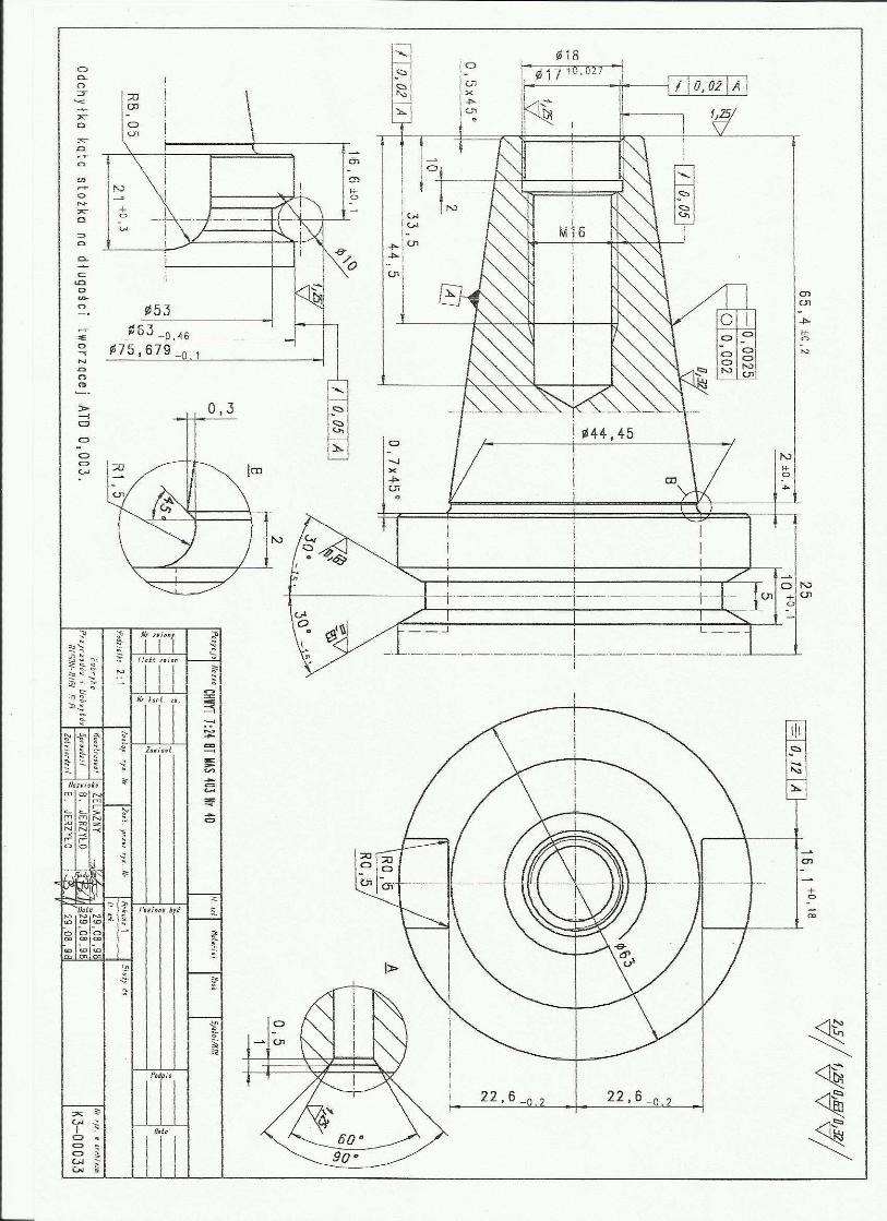
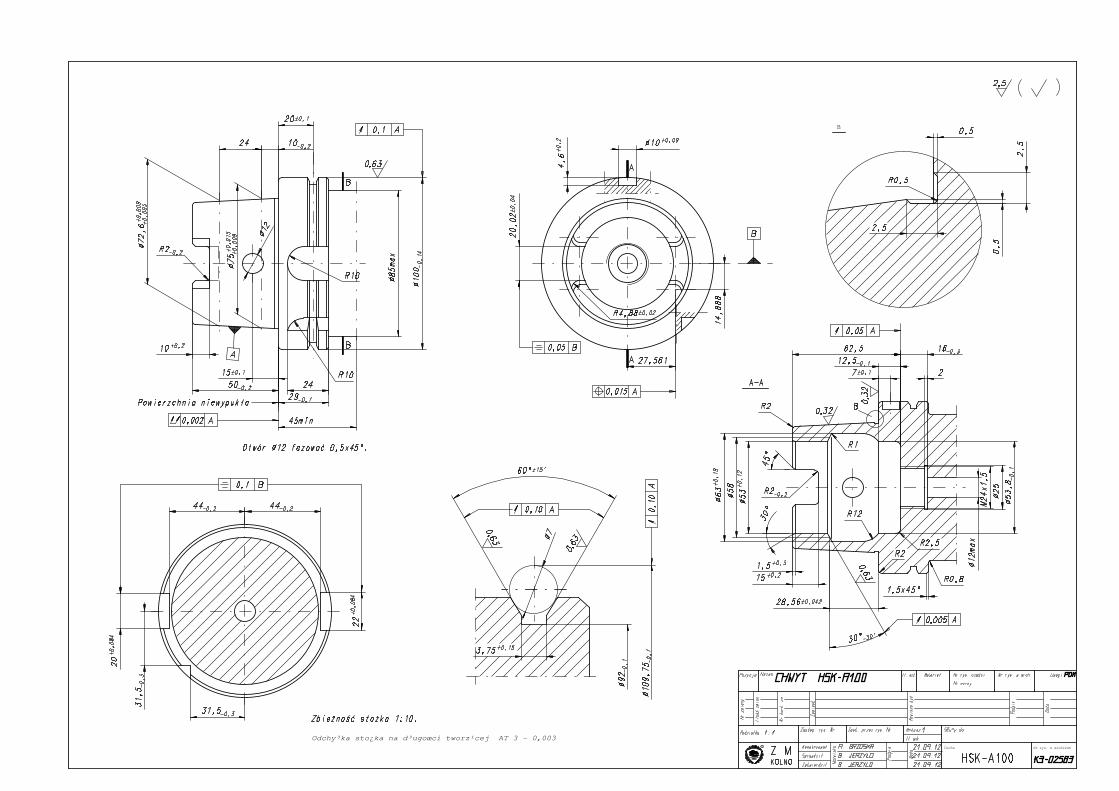
Odchy³ka k¹ta sto¿ka na d³ugoœci tworz¹cej ATD 0,003.
B
90°
60°
A
B
0,002
0,0025
2:1
29,08,98
29,08,98
29,08,98B. JERZY£O
B. JERZY£O
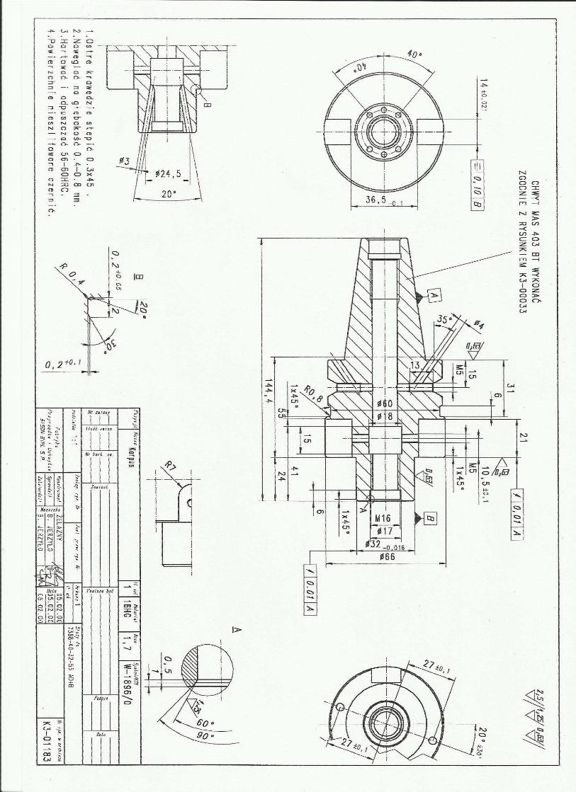
¯ELAZNY Nr rys.
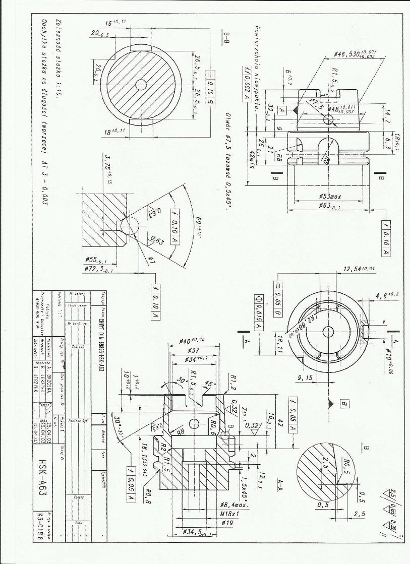
CHWYT 7:24 BT MAS 403 Nr 40
1
K3-00033
Cecha
1x45°
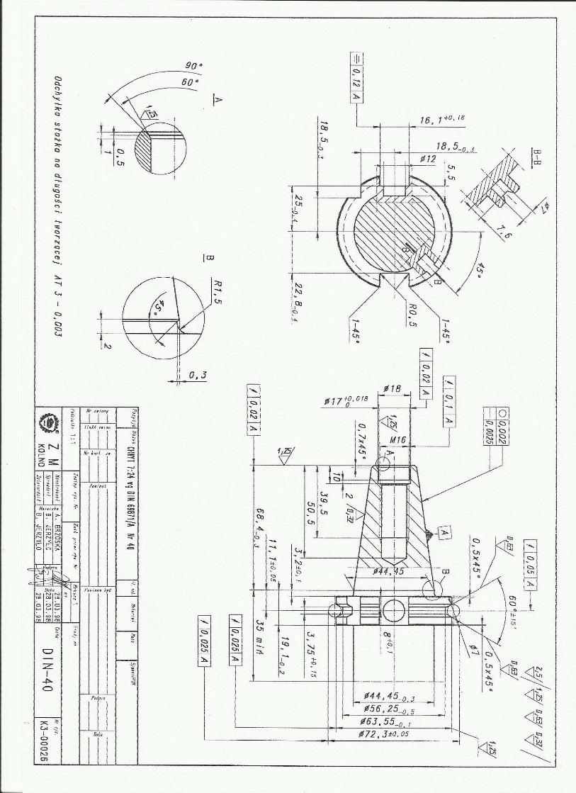
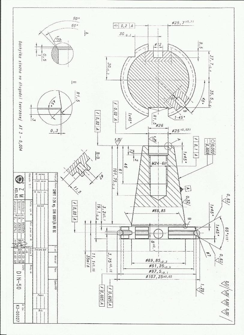
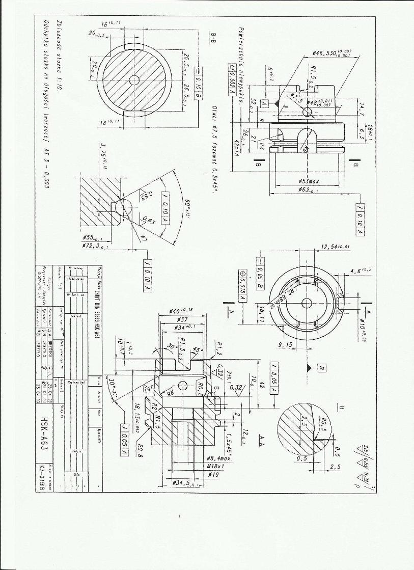
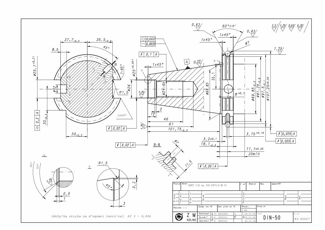
Odchy³ka sto¿ka na d³ugoœci tworz¹cej AT 3 - 0,004
A
B
B
60°
90°
A
1:1
28.03.98
28.03.98
28.03.98B. JERZY£O
B. JERZY£O
A. BRZÓSKA Nr rys.
CHWYT 7:24 wg. DIN 69871/A NR 50
1
K3-00027
Cecha
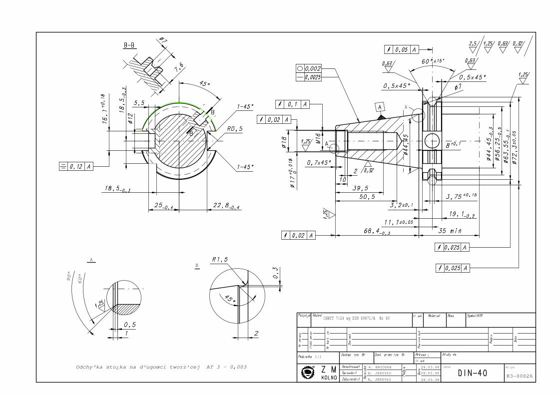
Odchy³ka sto¿ka na d³ugoœci tworz¹cej AT 3 - 0,003
B
B
60°
90°
A
1:1
28.03.98
28.03.98
28.03.98B, JERZY£O
B. JERZY£O
A. BRZÓSKA Nr rys.
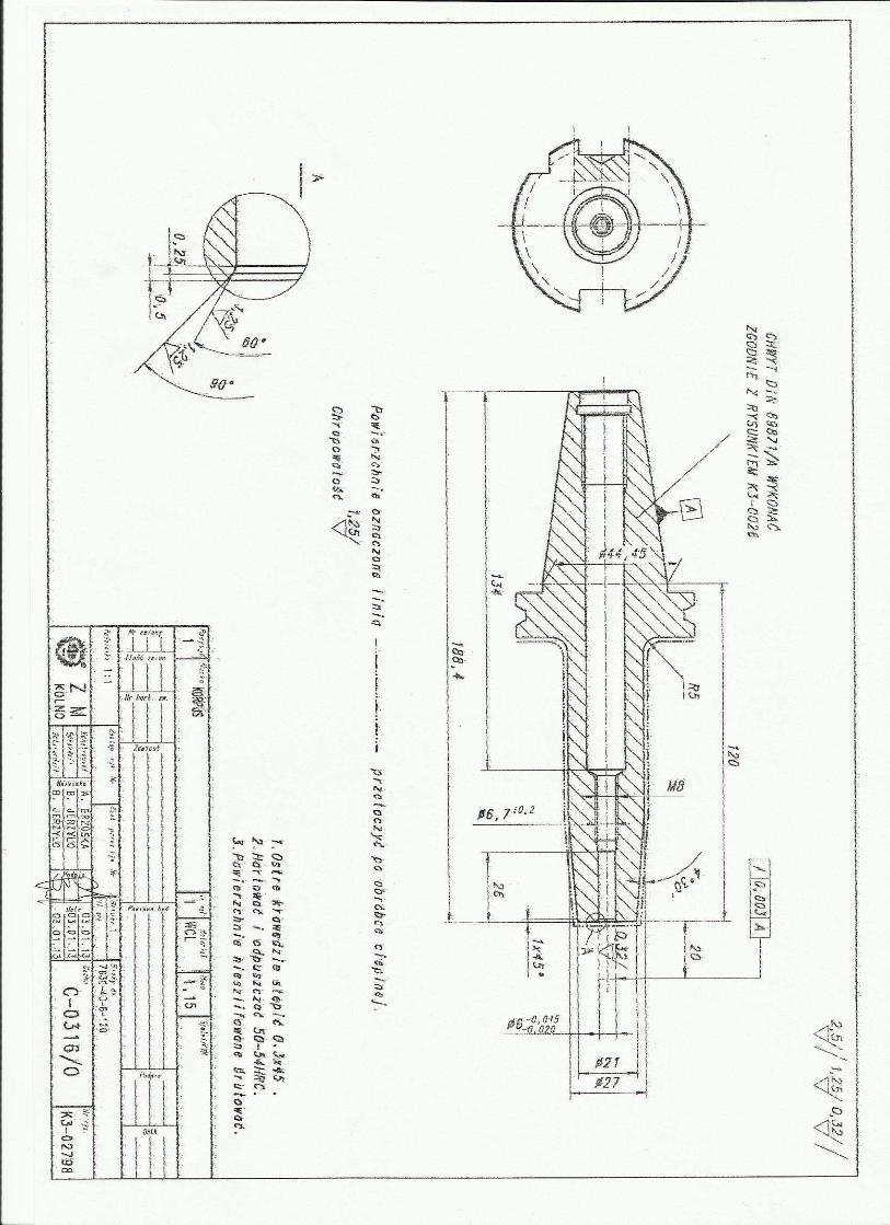
CHWYT 7:24 wg DIN 69871/A Nr 40
1
K3-00026
Cecha
B
Odchy³ka sto¿ka na d³ugoœci tworz¹cej AT 3 - 0,003
Cecha Nr rys. w archiwum
B
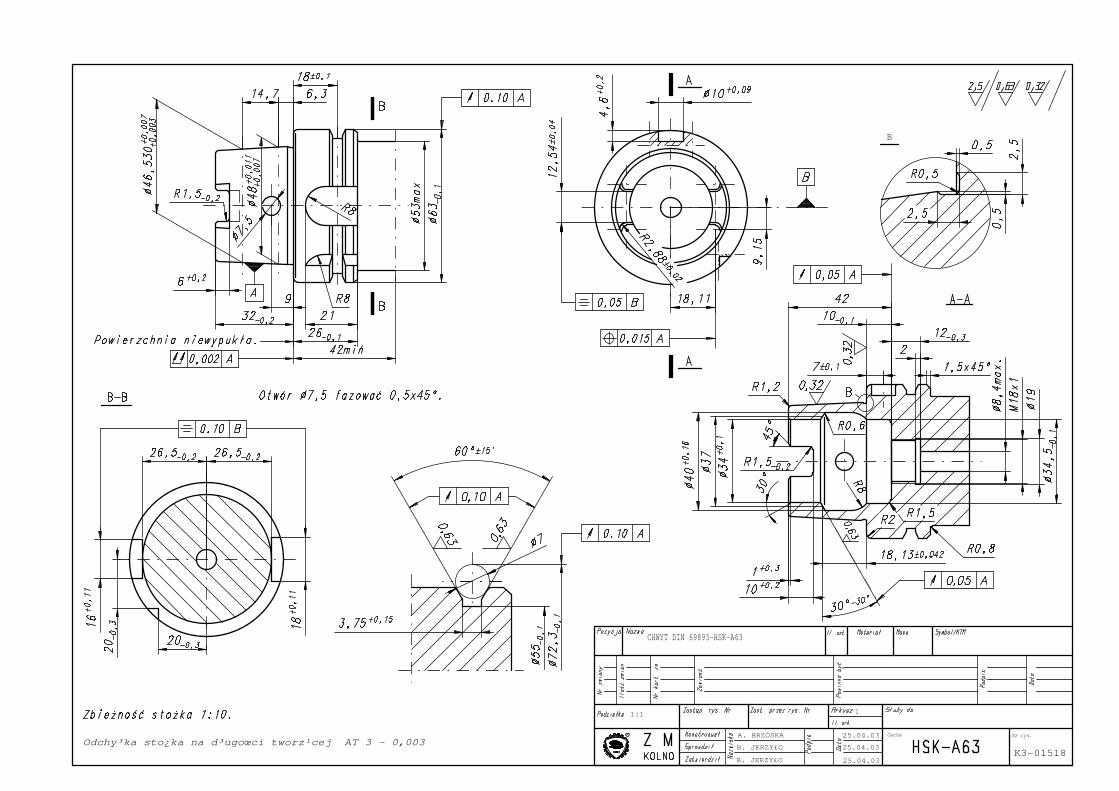
Odchy³ka sto¿ka na d³ugoœci tworz¹cej AT 3 - 0,003
1:1
25.04.03
25.04.03
25.04.03B. JERZY£O
B. JERZY£O
A. BRZÓSKA Nr rys.
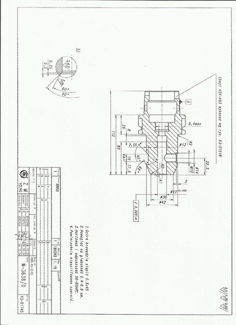
CHWYT DIN 69893-HSK-A63
1
K3-01518
Cecha
Reference numberISO 26623-1:2008(E)
© ISO 2008
INTERNATIONAL STANDARD
ISO26623-1
First edition2008-11-15
Polygonal taper interface with flange contact surface —
Part 1: Dimensions and designation of shanks
Interfaces à cône polygonal avec face d'appui —
Partie 1: Dimensions et désignation des queues
Copyright International Organization for Standardization
Provided by IHS under license with ISO
Not for ResaleNo reproduction or networking permitted without license from IHS
--`,,```,,,,````-`-`,,`,,`,`,,`---
ISO 26623-1:2008(E)
PDF disclaimer
This PDF file may contain embedded typefaces. In accordance with Adobe's licensing policy, this file may be printed or viewed but
shall not be edited unless the typefaces which are embedded are licensed to and installed on the computer performing the editing. In
downloading this file, parties accept therein the responsibility of not infringing Adobe's licensing policy. The ISO Central Secretariat
accepts no liability in this area.
Adobe is a trademark of Adobe Systems Incorporated.
Details of the software products used to create this PDF file can be found in the General Info relative to the file; the PDF-creation
parameters were optimized for printing. Every care has been taken to ensure that the file is suitable for use by ISO member bodies. In the unlikely event that a problem relating to it is found, please inform the Central Secretariat at the address given below.
COPYRIGHT PROTECTED DOCUMENT © ISO 2008
All rights reserved. Unless otherwise specified, no part of this publication may be reproduced or utilized in any form or by any means,
electronic or mechanical, including photocopying and microfilm, without permission in writing from either ISO at the address below or
ISO's member body in the country of the requester.
ISO copyright office
Case postale 56 • CH-1211 Geneva 20
Tel. + 41 22 749 01 11
Fax + 41 22 749 09 47
E-mail [email protected]
Web www.iso.org
Published in Switzerland
ii © ISO 2008 – All rights reserved
Copyright International Organization for Standardization
Provided by IHS under license with ISO
Not for ResaleNo reproduction or networking permitted without license from IHS
--`,,```,,,,````-`-`,,`,,`,`,,`---

ISO 26623-1:2008(E)
© ISO 2008 – All rights reserved iii
Foreword
ISO (the International Organization for Standardization) is a worldwide federation of national standards bodies (ISO member bodies). The work of preparing International Standards is normally carried out through ISO technical committees. Each member body interested in a subject for which a technical committee has been established has the right to be represented on that committee. International organizations, governmental and non-governmental, in liaison with ISO, also take part in the work. ISO collaborates closely with the International Electrotechnical Commission (IEC) on all matters of electrotechnical standardization.
International Standards are drafted in accordance with the rules given in the ISO/IEC Directives, Part 2.
The main task of technical committees is to prepare International Standards. Draft International Standards adopted by the technical committees are circulated to the member bodies for voting. Publication as an International Standard requires approval by at least 75 % of the member bodies casting a vote.
ISO 26623-1 was prepared by Technical Committee ISO/TC 29, Small tools.
ISO 26623 consists of the following parts, under the general title Polygonal taper interface with flange contact surface:
⎯ Part 1: Dimensions and designation of shanks
⎯ Part 2: Dimensions and designation of receivers
Copyright International Organization for Standardization
Provided by IHS under license with ISO
Not for ResaleNo reproduction or networking permitted without license from IHS
--`,,```,,,,````-`-`,,`,,`,`,,`---
ISO 26623-1:2008(E)
iv © ISO 2008 – All rights reserved
Introduction
The International Organization for Standardization (ISO) draws attention to the fact that it is claimed that compliance with this document may involve the use of a patent concerning the modular taper with ball track system.
ISO takes no position concerning the evidence, validity and scope of this patent right.
The holder of this patent right has assured ISO that he/she is willing to waive the exercise of this patent right throughout the world. In this respect, the statement of the holder of this patent right is registered with ISO. Information may be obtained from:
ISO Central Secretariat International Organization for Standardization (ISO) 1, chemin de la Voie-Creuse, Case postale 56 CH-1211 Geneva 20, Switzerland
Attention is drawn to the possibility that some of the elements in this document may be the subject of patent rights other than that identified above. ISO shall not be held responsible for identifying any or all such patent rights.
Copyright International Organization for Standardization
Provided by IHS under license with ISO
Not for ResaleNo reproduction or networking permitted without license from IHS
--`,,```,,,,````-`-`,,`,,`,`,,`---
INTERNATIONAL STANDARD ISO 26623-1:2008(E)
© ISO 2008 – All rights reserved 1
Polygonal taper interface with flange contact surface —
Part 1: Dimensions and designation of shanks
1 Scope
This part of ISO 26623 specifies the dimensions for polygonal taper interface with flange contact surface: polygon-shanks for automatic and manual tool exchange to be applied on machine tools (e.g. turning machines, drilling machines, milling machines and turn/milling centres, as well as grinding machines). A range of shank sizes is specified.
These shanks incorporate a grooved flange to enable automatic tool exchange. The clamping can be realized by a circular groove using clamping segments or internal screw threads using centre-bolts.
The torque is transmitted by form lock (polygon).
2 Normative references
The following referenced documents are indispensable for the application of this document. For dated references, only the edition cited applies. For undated references, the latest edition of the referenced document (including any amendments) applies.
ISO 965-2, ISO general purpose metric screw threads — Tolerances — Part 2: Limits of sizes for general purpose external and internal screw threads — Medium quality
ISO 2768-1, General tolerances — Part 1: Tolerances for linear and angular dimensions without individual tolerance indications
3 Dimensions
3.1 General
Tolerancing of linear and angular dimensions not specified shall be of tolerance class “m” in accordance with ISO 2768-1. Tolerances for threads where the tolerance is not stated shall be in accordance with ISO 965-2.
Copyright International Organization for Standardization
Provided by IHS under license with ISO
Not for ResaleNo reproduction or networking permitted without license from IHS
--`,,```,,,,````-`-`,,`,,`,`,,`---
ISO 26623-1:2008(E)
2 © ISO 2008 – All rights reserved
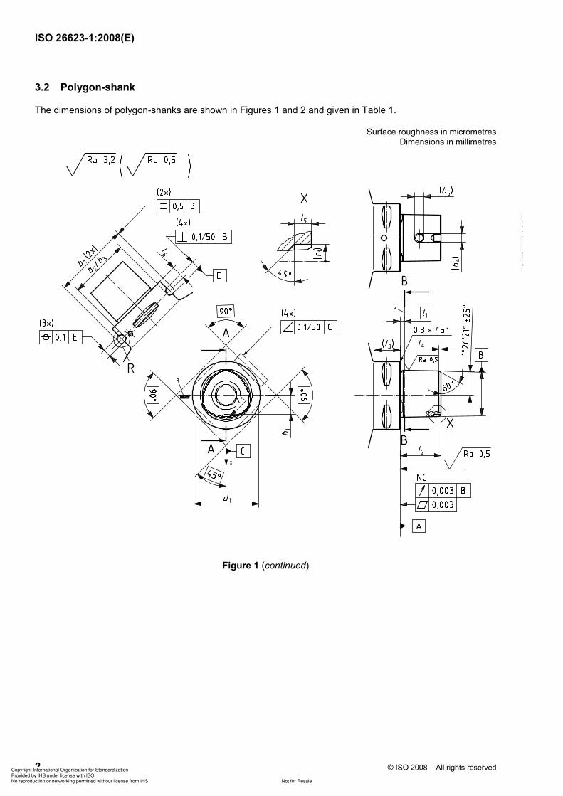
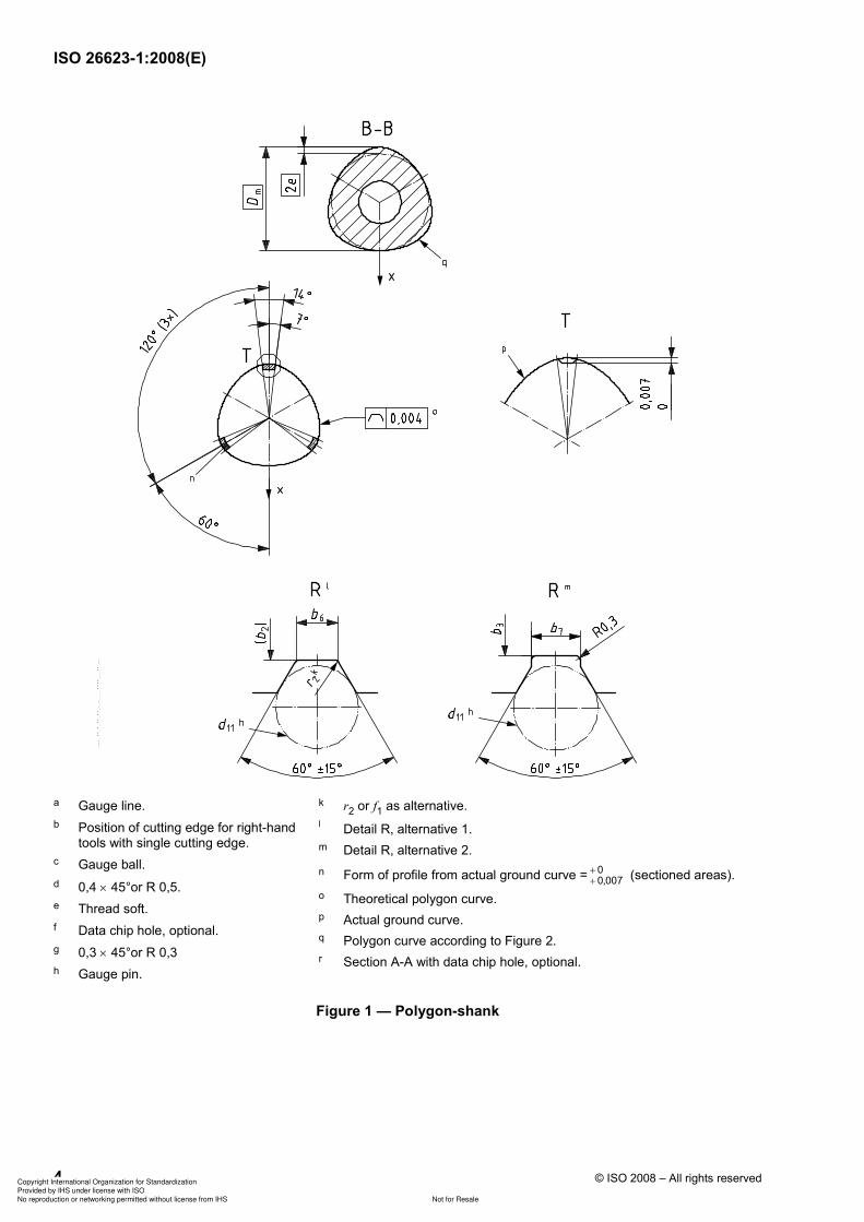
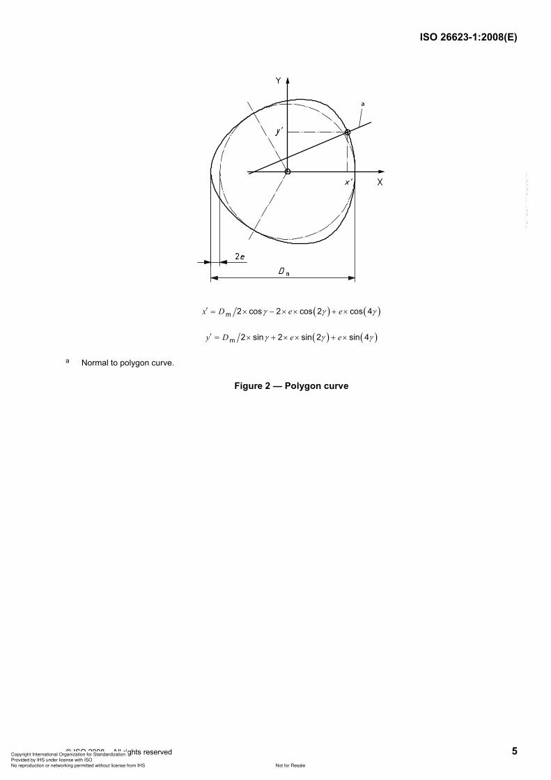
3.2 Polygon-shank
The dimensions of polygon-shanks are shown in Figures 1 and 2 and given in Table 1.
Surface roughness in micrometres Dimensions in millimetres
Figure 1 (continued)
Copyright International Organization for Standardization
Provided by IHS under license with ISO
Not for ResaleNo reproduction or networking permitted without license from IHS
--`,,```,,,,````-`-`,,`,,`,`,,`---
ISO 26623-1:2008(E)
© ISO 2008 – All rights reserved 3
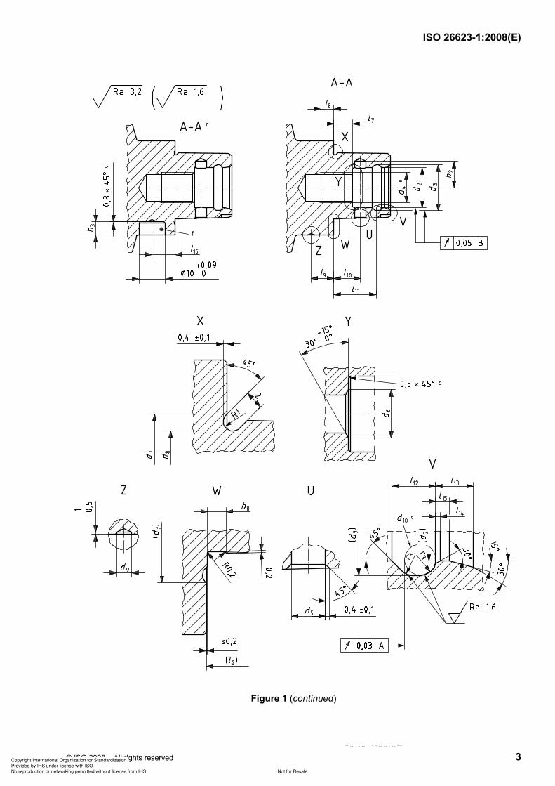
Figure 1 (continued)
Copyright International Organization for Standardization
Provided by IHS under license with ISO
Not for ResaleNo reproduction or networking permitted without license from IHS
--`,,```,,,,````-`-`,,`,,`,`,,`---
ISO 26623-1:2008(E)
4 © ISO 2008 – All rights reserved
a Gauge line.
b Position of cutting edge for right-hand tools with single cutting edge.
c Gauge ball.
d 0,4 × 45°or R 0,5.
e Thread soft.
f Data chip hole, optional.
g 0,3 × 45°or R 0,3
h Gauge pin.
k r2 or f1 as alternative.
l Detail R, alternative 1.
m Detail R, alternative 2.
n Form of profile from actual ground curve = 0
0,007++ (sectioned areas).
o Theoretical polygon curve.
p Actual ground curve.
q Polygon curve according to Figure 2.
r Section A-A with data chip hole, optional.
Figure 1 — Polygon-shank
Copyright International Organization for Standardization
Provided by IHS under license with ISO
Not for ResaleNo reproduction or networking permitted without license from IHS
--`,,```,,,,````-`-`,,`,,`,`,,`---
ISO 26623-1:2008(E)
© ISO 2008 – All rights reserved 5
( ) ( )m 2 cos 2 cos 2 cos 4x D e e′ = × − × × + ×γ γ γ
( ) ( )m 2 sin 2 sin 2 sin 4y D e e′ = × + × × + ×γ γ γ
a Normal to polygon curve.
Figure 2 — Polygon curve
Copyright International Organization for Standardization
Provided by IHS under license with ISO
Not for ResaleNo reproduction or networking permitted without license from IHS
--`,,```,,,,````-`-`,,`,,`,`,,`---
ISO 26623-1:2008(E)
6 © ISO 2008 – All rights reserved
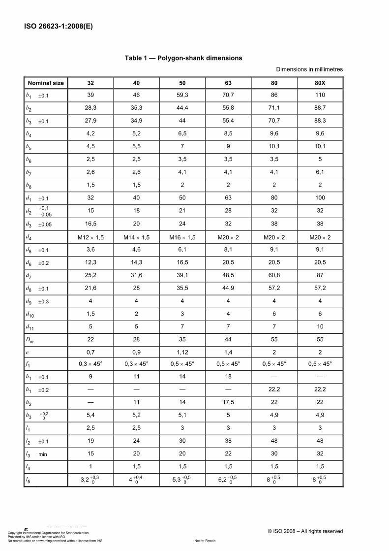
Table 1 — Polygon-shank dimensions
Dimensions in millimetres
Nominal size 32 40 50 63 80 80X
b1 ±0,1 39 46 59,3 70,7 86 110
b2 28,3 35,3 44,4 55,8 71,1 88,7
b3 ±0,1 27,9 34,9 44 55,4 70,7 88,3
b4 4,2 5,2 6,5 8,5 9,6 9,6
b5 4,5 5,5 7 9 10,1 10,1
b6 2,5 2,5 3,5 3,5 3,5 5
b7 2,6 2,6 4,1 4,1 4,1 6,1
b8 1,5 1,5 2 2 2 2
d1 ±0,1 32 40 50 63 80 100
d2 +0,1
−0,05 15 18 21 28 32 32
d3 ±0,05 16,5 20 24 32 38 38
d4 M12 × 1,5 M14 × 1,5 M16 × 1,5 M20 × 2 M20 × 2 M20 × 2
d5 ±0,1 3,6 4,6 6,1 8,1 9,1 9,1
d6 ±0,2 12,3 14,3 16,5 20,5 20,5 20,5
d7 25,2 31,6 39,1 48,5 60,8 87
d8 ±0,1 21,6 28 35,5 44,9 57,2 57,2
d9 ±0,3 4 4 4 4 4 4
d10 1,5 2 3 4 6 6
d11 5 5 7 7 7 10
Dm 22 28 35 44 55 55
e 0,7 0,9 1,12 1,4 2 2
f1 0,3 × 45° 0,3 × 45° 0,5 × 45° 0,5 × 45° 0,5 × 45° 0,5 × 45°
h1 ±0,1 9 11 14 18 — —
h1 ±0,2 — — — — 22,2 22,2
h2 — 11 14 17,5 22 22
h3 0,20
+ 5,4 5,2 5,1 5 4,9 4,9
l1 2,5 2,5 3 3 3 3
l2 ±0,1 19 24 30 38 48 48
l3 min 15 20 20 22 30 32
l4 1 1,5 1,5 1,5 1,5 1,5
l5 3,2 0,30+ 4 0,4
0+ 5,3 0,5
0+ 6,2 0,5
0+ 8 0,5
0+ 8 0,5
0+
Copyright International Organization for Standardization
Provided by IHS under license with ISO
Not for ResaleNo reproduction or networking permitted without license from IHS
--`,,```,,,,````-`-`,,`,,`,`,,`---
ISO 26623-1:2008(E)
© ISO 2008 – All rights reserved 7
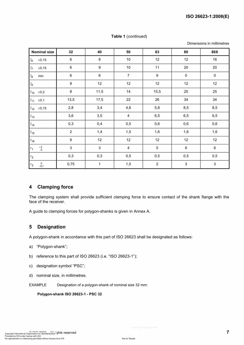
Table 1 (continued)
Dimensions in millimetres
Nominal size 32 40 50 63 80 80X
l6 ±0,15 6 8 10 12 12 16
l7 ±0,15 6 9 10 11 20 20
l8 min 6 6 7 9 0 0
l9 9 12 12 12 12 12
l10 ±0,2 8 11,5 14 15,5 25 25
l11 ±0,1 13,5 17,5 22 26 34 34
l12 ±0,15 2,8 3,4 4,6 5,8 8,5 8,5
l13 3,6 3,5 4 6,5 6,5 6,5
l14 0,3 0,4 0,5 0,6 0,6 0,6
l15 2 1,4 1,5 1,6 1,6 1,6
l16 9 12 12 12 12 12
r1 20
+ 3 3 4 5 6 6
r2 0,3 0,3 0,5 0,5 0,5 0,5
r3 00,1− 0,75 1 1,5 2 3 3
4 Clamping force
The clamping system shall provide sufficient clamping force to ensure contact of the shank flange with the face of the receiver.
A guide to clamping forces for polygon-shanks is given in Annex A.
5 Designation
A polygon-shank in accordance with this part of ISO 26623 shall be designated as follows:
a) “Polygon-shank”;
b) reference to this part of ISO 26623 (i.e. “ISO 26623-1”);
c) designation symbol “PSC”;
d) nominal size, in millimetres.
EXAMPLE Designation of a polygon-shank of nominal size 32 mm:
Polygon-shank ISO 26623-1 - PSC 32
Copyright International Organization for Standardization
Provided by IHS under license with ISO
Not for ResaleNo reproduction or networking permitted without license from IHS
--`,,```,,,,````-`-`,,`,,`,`,,`---

ISO 26623-1:2008(E)
8 © ISO 2008 – All rights reserved
Annex A (informative)
Recommendations for use and application
A.1 Clamping forces
Variations of taper shank and receiver size within the specified limits of tolerances will cause the portion of the clamping force acting on the flange surface to vary. The flange contact surface is decisive for the stiffness of the polygon taper surface. However, the clamping forces given in Table A.1 will ensure that the portion acting on the flange surface is never less than 80 % of the total.
Table A.1 — Range of clamping forces
Nominal size 32 40 50 63 80 80X
Clamping force, kN 15 20 25 30 40 40
Lower clamping forces can be sufficient when operational loads are low (e.g. cutting and feed forces in finish machining).
Conversely, higher clamping forces can be required when high operational loads are encountered (e.g. cutting and feed forces in heavy machining).
A.2 Information about speeds, torques, bending loads and stiffness
The manufacturer should provide information regarding permissible speeds, torque-transmitting capacities, bending loads and stiffness.
A.3 Material and heat treatment
Material and heat-treatment specifications for polygon taper shanks should be selected considering strength, hardness, case depth (if not through-hardened), as well as toughness and wear requirements.
It is recommended that coupling be either through-hardened or surface-hardened, depending on which is suitable for the range of application.
A.4 General surface hardness recommendations
Tapered polygon, internal clamping groove and axial contact surface: HRC 42 minimum.
External gripper groove area: HRC 51 minimum.
A.5 Balancing
If the polygonal taper shank requires balancing before tools or equipment are assembled onto it, the shank may be balanced with a hole located as shown in Figure A.1 and in accordance with Table A.2.
NOTE The balancing hole is used exclusively for compensation of coolant hole and orientation recess on the polygonal taper (balanced by design). The data chip hole is not taken into consideration.
Copyright International Organization for Standardization
Provided by IHS under license with ISO
Not for ResaleNo reproduction or networking permitted without license from IHS
--`,,```,,,,````-`-`,,`,,`,`,,`---
ISO 26623-1:2008(E)
© ISO 2008 – All rights reserved 9
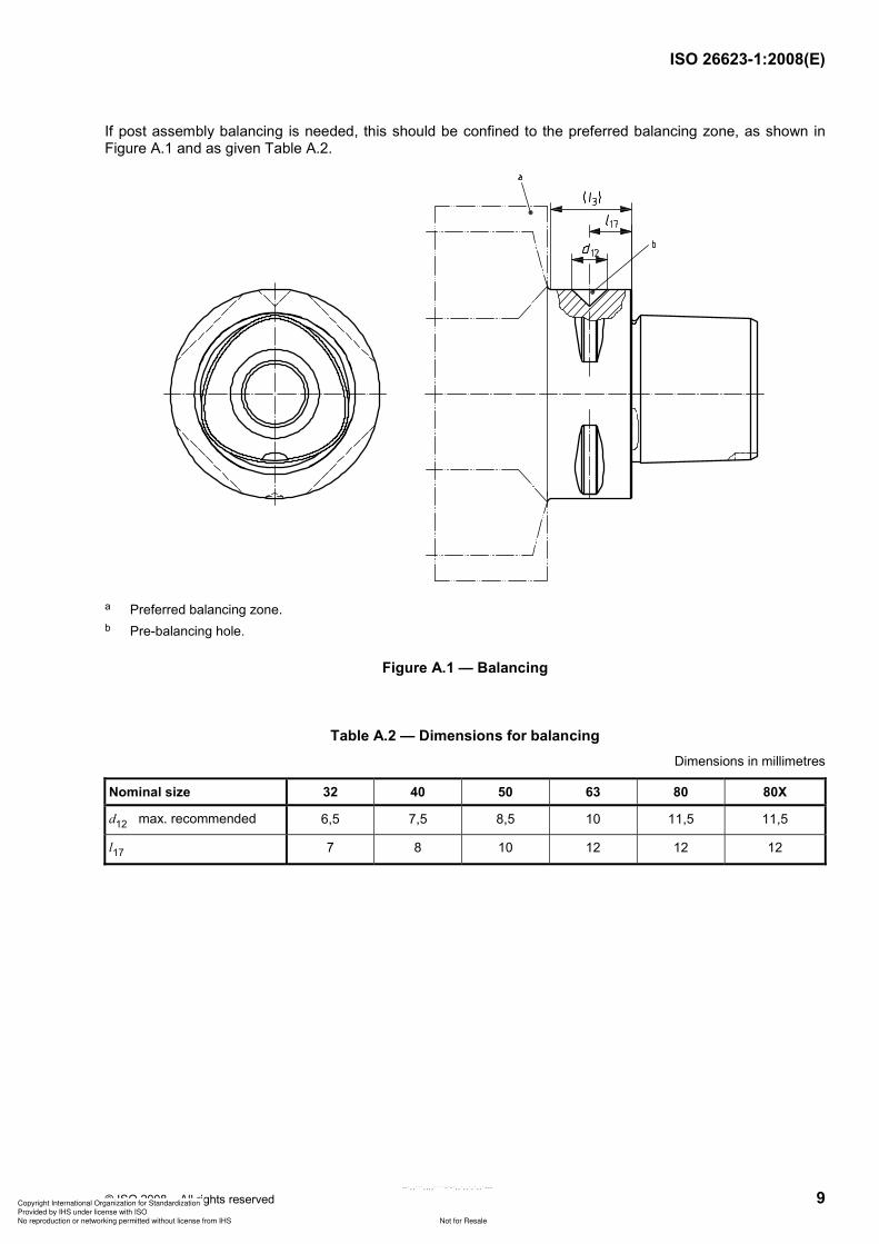
If post assembly balancing is needed, this should be confined to the preferred balancing zone, as shown in Figure A.1 and as given Table A.2.
a Preferred balancing zone.
b Pre-balancing hole.
Figure A.1 — Balancing
Table A.2 — Dimensions for balancing
Dimensions in millimetres
Nominal size 32 40 50 63 80 80X
d12 max. recommended 6,5 7,5 8,5 10 11,5 11,5
l17 7 8 10 12 12 12
Copyright International Organization for Standardization
Provided by IHS under license with ISO
Not for ResaleNo reproduction or networking permitted without license from IHS
--`,,```,,,,````-`-`,,`,,`,`,,`---

ISO 26623-1:2008(E)
ICS 25.060.20
Price based on 9 pages
© ISO 2008 – All rights reserved
Copyright International Organization for Standardization
Provided by IHS under license with ISO
Not for ResaleNo reproduction or networking permitted without license from IHS
--`,,```,,,,````-`-`,,`,,`,`,,`---
A
A 5,6 1x45
0,5x45
4
0,7
138
43 4,5
68 83
63
M30
x1,5
LH
1°2
5'31
"
48
,5
100 2,8
A
B
B
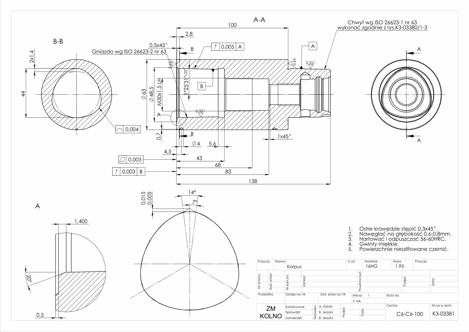
A-A Chwyt wg ISO 26623-1 nr 63wykonać zgodnie z rys.K3-03380/1-3
Gniazdo wg ISO 26623-2 nr 63
0,32
0,32
0,63 0,
63
0,003
0,003 B
0,005 A A
B
1,400
0,5
20°
A
44
2x1
,4
B-B
0,004
14°
0,01
50,
005
7°
25"
Korpus
1
A. Górski
B. Jerzyło
B. Jerzyło
1.95 16HG
Nr rys w arch.Cecha
Zatwierdził
Sprawdził
Konstruował
Da
ta
Pod
pis
Na
zwisk
o
Da
ta
Pod
pis
Pow
inno
być
Zam
iast
Nr k
art
zm.
ilość
zm
ian
Nr z
mia
ny
Służy do
il. ark.
ArkuszZast. przez rys. NrZastęp rys. Nr
PozycjaMasaMateriałil. szt.NazwaPozycja
Podziałka
ZMKOLNO C6-C6-100
Ostre krawędzie stępić 0,3x45 .1.Nawęglać na głębokość 0,6-0,8mm.2.Hartować i odpuszczać 56-60HRC.3.Gwinty miękkie.4.Powierzchnie nieszlifowane czernić.5.
K3-03381
18
±0,1
R6
A
A
17,
50
28
32
9
15,60
11
12 4 ±0,30
0,7
0 ±0
,20 M
20x2
0,5 X 45°
20
,50 30°
8,10 ±0,10
0,4 X 45°
AB
cD
A-A
0,05
A
A
6,30 + 0,200
45°
ASKALA 5 : 1
0,10
0,2
0
2
BSKALA 5 : 1
R0,2R0,2
0,63
0,30 + 0,100
2
R1
cSKALA 5 : 1
44,9
0,1
48,5
30°
1
5°
30°
0,60
1,60
6,50 5,80
45°
R2 R2
4
D
SKALA 5 : 1 0,63
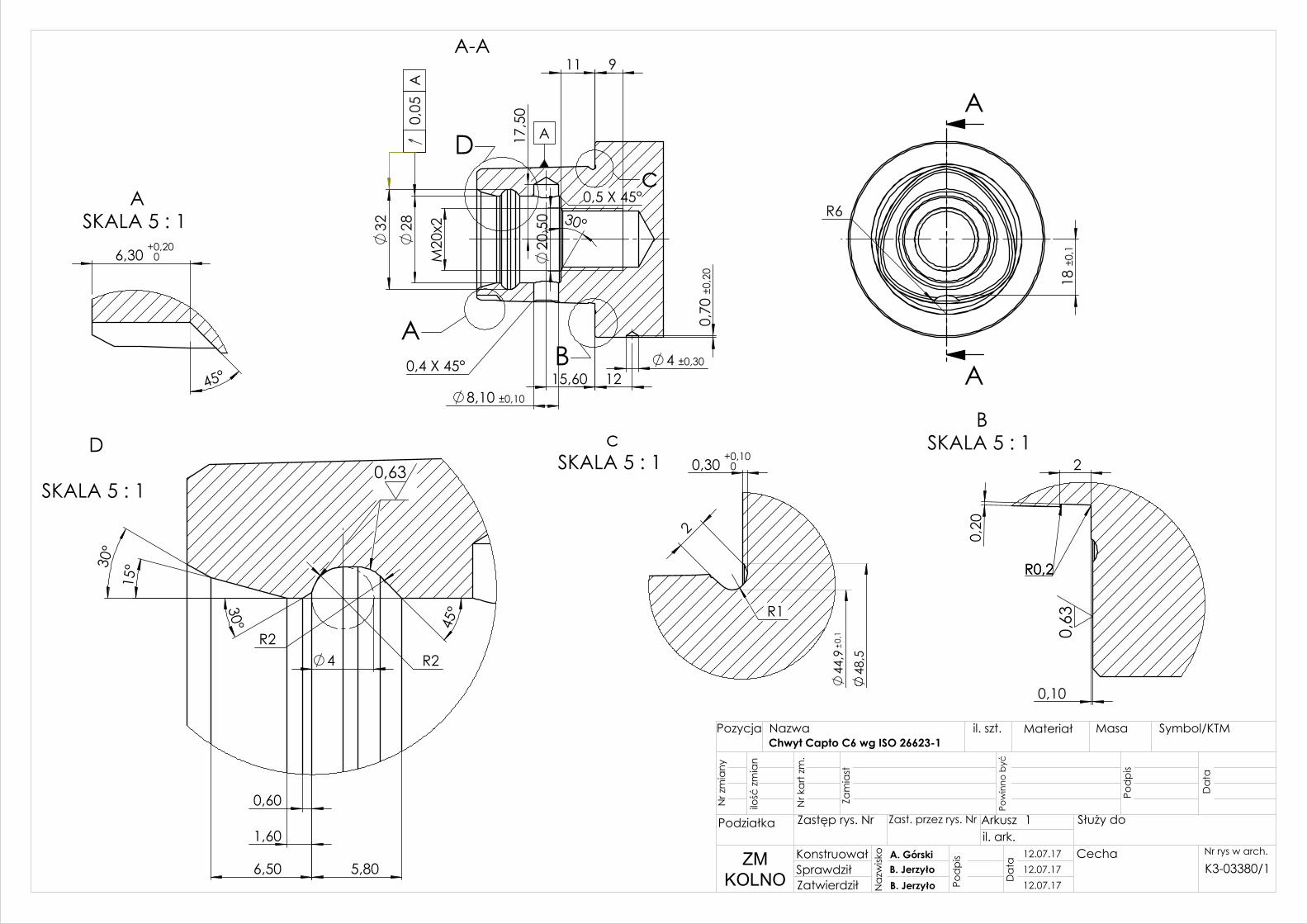
Chwyt Capto C6 wg ISO 26623-1
1
A. GórskiB. JerzyłoB. Jerzyło
Nr rys w arch. Cecha
ZatwierdziłSprawdziłKonstruował
Da
ta
Pod
pis
Na
zwisk
o
Da
ta
Pod
pis
Pow
inno
być
Zam
iast
Nr k
art
zm.
ilość
zm
ian
Nr z
mia
ny
Służy doil. ark.ArkuszZast. przez rys. NrZastęp rys. Nr
Symbol/KTMMasaMateriałil. szt.NazwaPozycja
Podziałka
ZMKOLNO
12.07.1712.07.1712.07.17
K3-03380/1
3
A
A
B
B
90°
90°
90°
45°
A-A 0,1/50 B
B
Dm=44 ±0,002
2e=2,8
B-BSKALA 2 : 1
x'
y'
120
°
120°
7°
14°
0 0,00
70,004
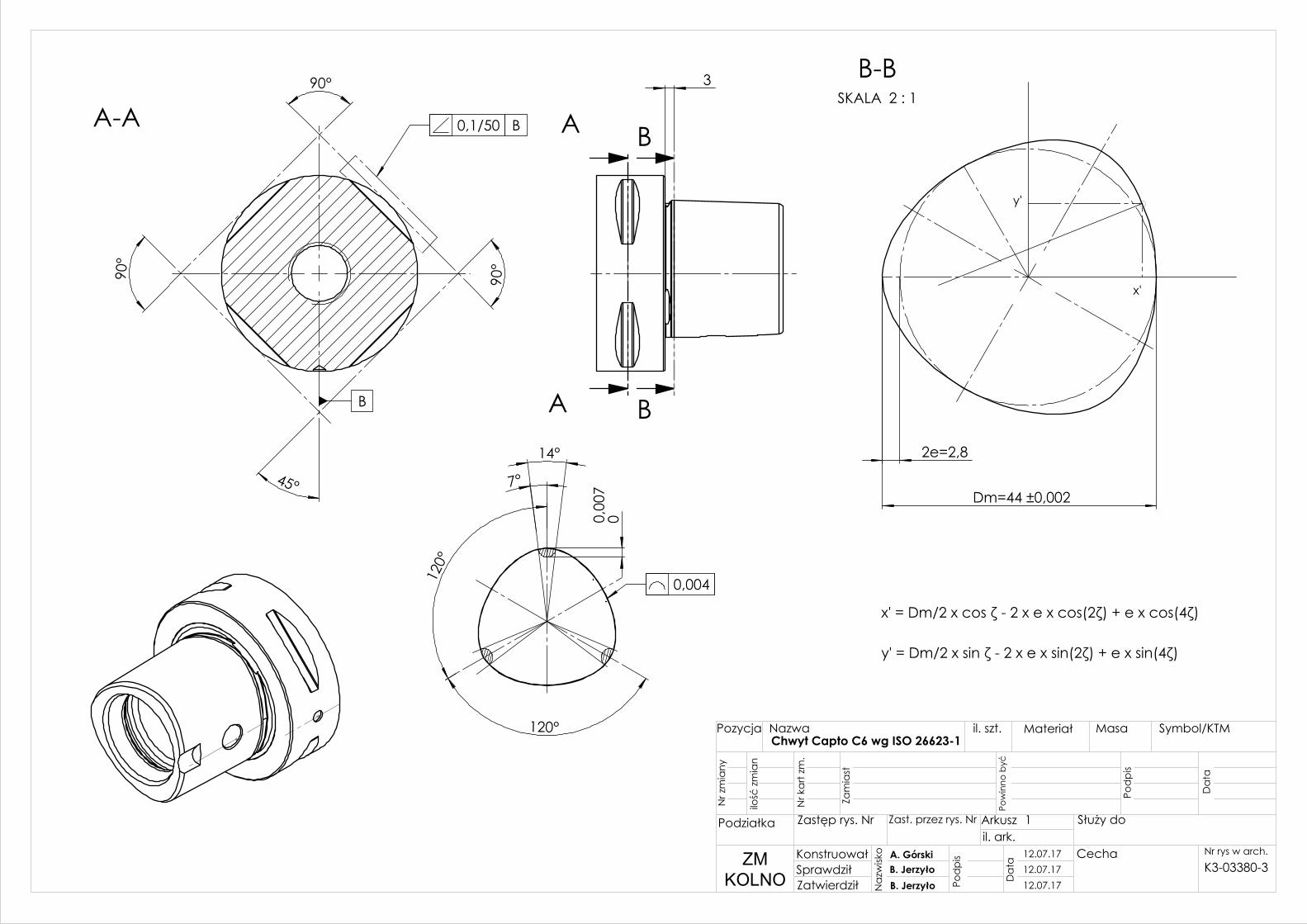
x' = Dm/2 x cos ζ - 2 x e x cos(2ζ) + e x cos(4ζ)
y' = Dm/2 x sin ζ - 2 x e x sin(2ζ) + e x sin(4ζ)
Chwyt Capto C6 wg ISO 26623-1
1
A. GórskiB. JerzyłoB. Jerzyło
Nr rys w arch. Cecha
ZatwierdziłSprawdziłKonstruował
Da
ta
Pod
pis
Na
zwisk
o
Da
ta
Pod
pis
Pow
inno
być
Zam
iast
Nr k
art
zm.
ilość
zm
ian
Nr z
mia
ny
Służy doil. ark.ArkuszZast. przez rys. NrZastęp rys. Nr
Symbol/KTMMasaMateriałil. szt.NazwaPozycja
Podziałka
ZMKOLNO
12.07.1712.07.1712.07.17
K3-03380-3
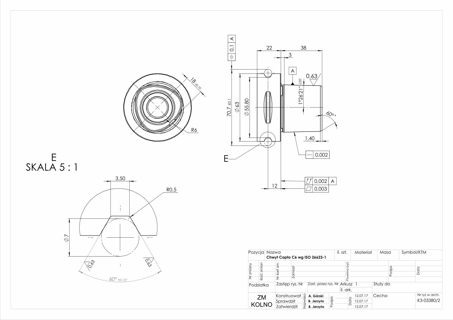
R6
18 ±0,10
12
55
,80
63
1°2
6'21
"
22 3
1,40
60°
38
70,
7 ±0
,1
E
25" 0,63
0,1
A
0,002 A
0,002
0.003
A
60° ±0,15°
R0,5
3,50
7
ESKALA 5 : 1
0,63
0,63
Chwyt Capto C6 wg ISO 26623-1
1
A. GórskiB. JerzyłoB. Jerzyło
Nr rys w arch. Cecha
ZatwierdziłSprawdziłKonstruował
Da
ta
Pod
pis
Na
zwisk
o
Da
ta
Pod
pis
Pow
inno
być
Zam
iast
Nr k
art
zm.
ilość
zm
ian
Nr z
mia
ny
Służy doil. ark.ArkuszZast. przez rys. NrZastęp rys. Nr
Symbol/KTMMasaMateriałil. szt.NazwaPozycja
Podziałka
ZMKOLNO
12.07.1712.07.1712.07.17
K3-03380/2
A1
1
0,5
60°
90°
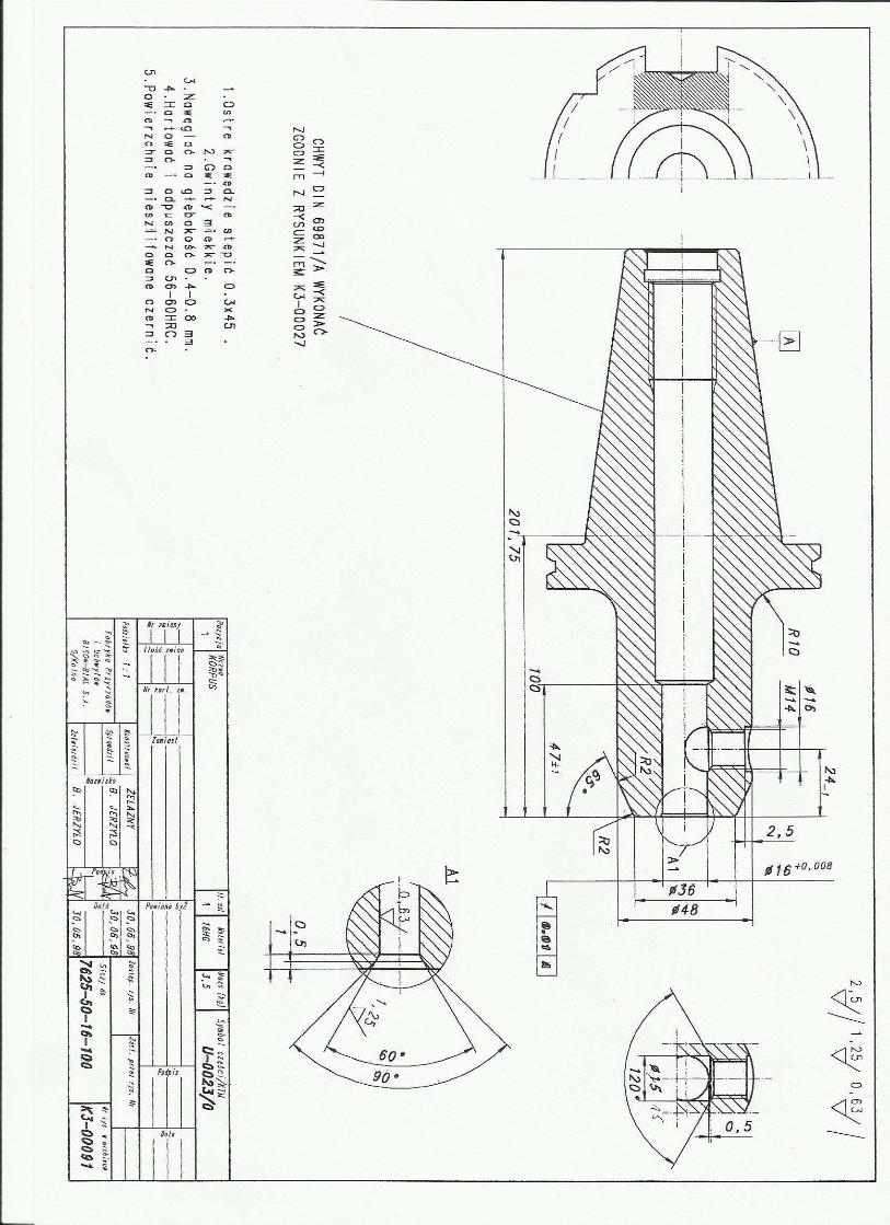
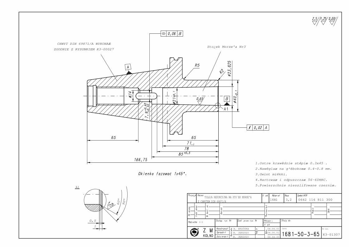
CHWYT DIN 69871/A WYKONAÆ
ZGODNIE Z RYSUNKIEM K3-00027Sto¿ek Morse'a Nr3
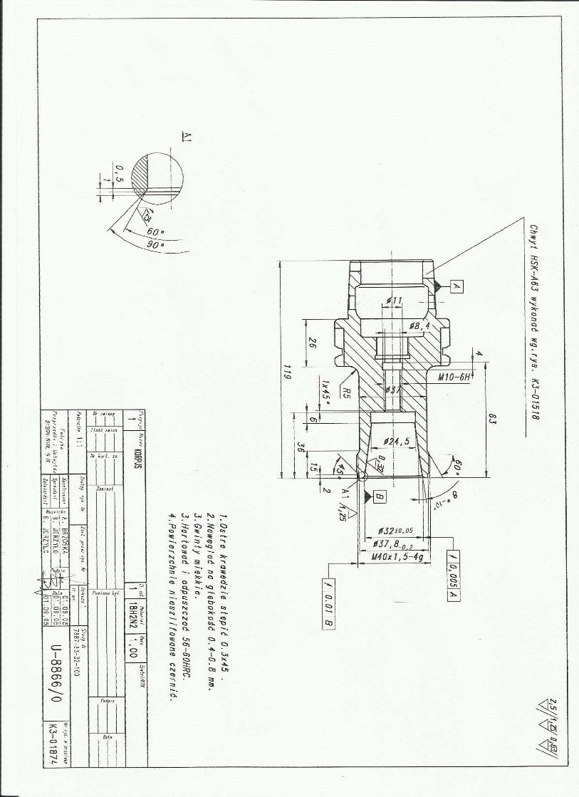
1.Ostre krawêdzie stêpiæ 0.3x45 .
2.Nawêglaæ na g³êbokoœæ 0.4-0.8 mm.
3.Gwint miêkki.
4.Hartowaæ i odpuszczaæ 56-60HRC.
5.Powierzchnie nieszlifowane czerniæ.
1:1
04.06.01
04.06.01
04.06.01B. JERZY£O
B. JERZY£O
A. BRZÓSKA Nr rys.
TULEJA REDUKCYJNA NA STO¯EK MORSE'A
Z CHWYTEM DIN 69871/A
1
K3-01307
3,216HG
Cecha
0642 116 811 300