
Design and performance study of a small-scale waste … · stator outflow angle which is about 4.5...
18
TRANSACTIONS OF THE INSTITUTE OF FLUID-FLOW MACHINERY No. 133, 2016, 145–162 Roman Rusanov a∗ , Łukasz Jędrzejewski a , Piotr Klonowicz a , Grzegorz Żywica a Piotr Lampart a , A. Rusanov b Design and performance study of a small-scale waste heat recovery turbine a Institute of Fluid Flow Machinery, Polish Academy of Sciences, 80-231 Gdańsk, Fiszera 14, Poland b A.N. Podgorny Institute of Mechanical Engineering Problems National Academy of Sciences of Ukraine, Kharkov, Ukraine Abstract The paper presents the design process of a radial-axial turbine working with SES36 working fluid. First, the mean-line design process is performed and then the geometry is developed. In the next stage the numerical verification is performed taking into account the real properties of the working fluid. The properties are implemented via a look-up table and by a modified Benedict-Webb-Rubin equation of state. The presented turbine is characterized by a very small stator outflow angle which is about 4.5 ◦ but despite this small value, the efficiency of the machine is relatively high and equal to about 88%. The influence of internal leakages has also been investigated. Keywords: Cogeneration unit; Low-boiling working media; Numerical method; Turbine; Radial- axial stage 1 Introduction A promising direction of development of energy-saving technologies for Europe is application of small power cogeneration plants operating with the low-boiling working media organic Rankine cycle (ORC), [1–4]. Such systems can also be used to utilize low-temperature waste heat, and work with renewable fuels – various ∗ Corresponding Author. Email adress: [email protected] ISSN 0079-3205 Transactions IFFM 133(2016) 145–162
Transcript of Design and performance study of a small-scale waste … · stator outflow angle which is about 4.5...
TRANSACTIONS OF THE INSTITUTE OF FLUID-FLOW MACHINERY
No. 133, 2016, 145–162
Roman Rusanova∗, Łukasz Jędrzejewskia, Piotr Klonowicza, Grzegorz Żywicaa
Piotr Lamparta, A. Rusanovb
Design and performance study of a small-scale wasteheat recovery turbine
a Institute of Fluid Flow Machinery, Polish Academy of Sciences,80-231 Gdańsk, Fiszera 14, Poland
b A.N. Podgorny Institute of Mechanical Engineering ProblemsNational Academy of Sciences of Ukraine, Kharkov, Ukraine
AbstractThe paper presents the design process of a radial-axial turbine working with SES36 workingfluid. First, the mean-line design process is performed and then the geometry is developed. Inthe next stage the numerical verification is performed taking into account the real propertiesof the working fluid. The properties are implemented via a look-up table and by a modifiedBenedict-Webb-Rubin equation of state. The presented turbine is characterized by a very smallstator outflow angle which is about 4.5◦ but despite this small value, the efficiency of themachine is relatively high and equal to about 88%. The influence of internal leakages has alsobeen investigated.
Keywords: Cogeneration unit; Low-boiling working media; Numerical method; Turbine; Radial-axial stage
1 Introduction
A promising direction of development of energy-saving technologies for Europeis application of small power cogeneration plants operating with the low-boilingworking media organic Rankine cycle (ORC), [1–4]. Such systems can also be usedto utilize low-temperature waste heat, and work with renewable fuels – various
∗Corresponding Author. Email adress: [email protected]
ISSN 0079-3205 Transactions IFFM 133(2016) 145–162
146 R. Rusanov et al.
types of biomass. The turbine is an important element of such cogenerationplants. The peculiarity of these turbines is their usually relatively small size, whichcomplicates the task of achieving an acceptable level of gas-dynamic efficiency.
2 Plant layout. The initial data for the creation of
a turbine
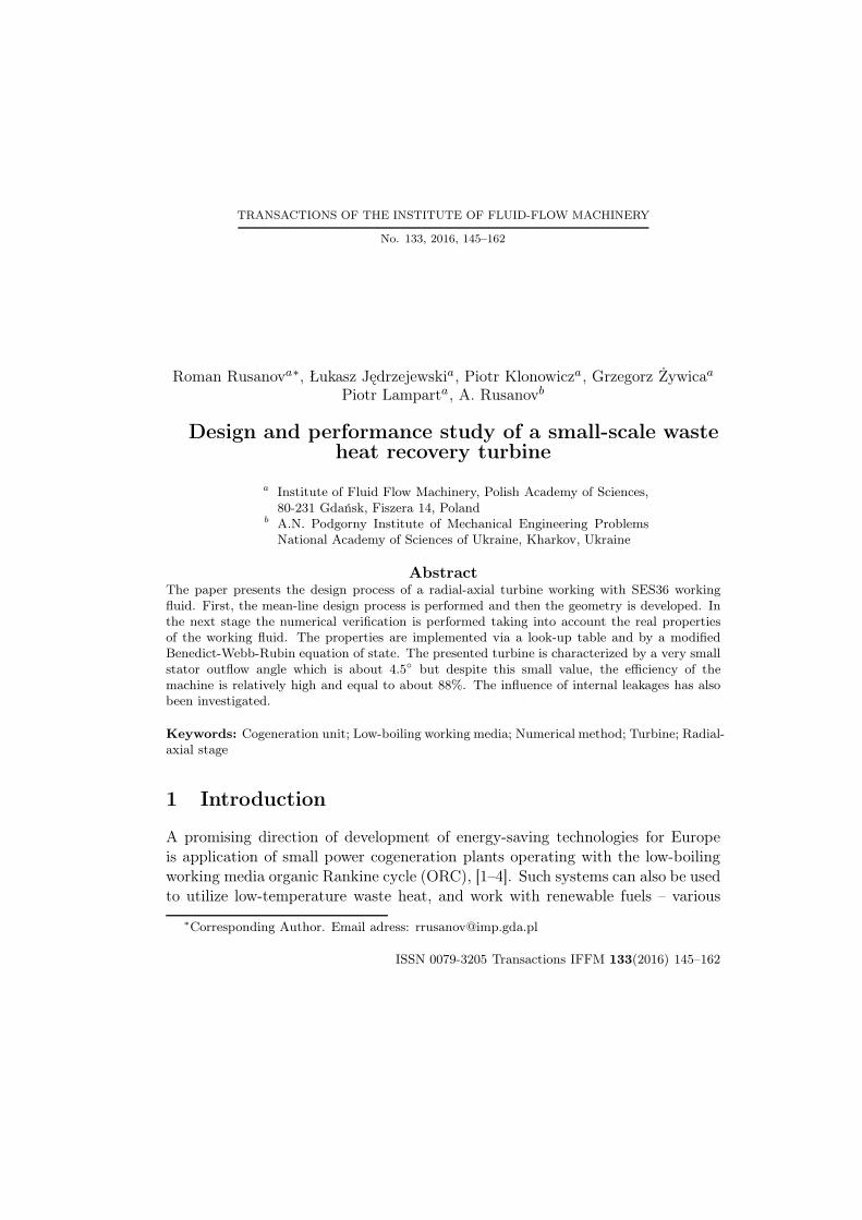
The ORC systems are similar to the steam cycles used in the large power industry.The fields of application of both technologies are roughly shown in Fig. 1 [5].
Figure 1: Fields of application of ORC systems and traditional steam systems [5].
The Institute of Fluid Flow Machinery, Polish Academy of Sciencies (IMP PAN)has built a combined gas-vapour cycle with the nominal power of about 400 kWand a high electrical efficiency. The primary generation unit is an internal com-bustion engine fuelled by natural gas which can also be fuelled by biogas andsyngas in real applications and distributed cogeneration. At least two variantsof such a system can be considered. For example, the ORC itself can work forcogeneration and accept both the exhaust heat and heat from the engine coolingloop. Alternatively, the ORC can work to produce only electrical power while theheat from the engine’s cooling loop can directly be used for heating.
The system build at IMP PAN makes use of the second option. The schematicof the cogeneration plant and its photographs are shown in Figs. 2 and 3. Asa working fluid, the substance SES36 has been used. The medium delivering
ISSN 0079-3205 Transactions IFFM 133(2016) 145–162

Design and performance study of a small-scale waste. . . 147147
the heat from the engine exhaust to the ORC is a high temperature thermal oilVeco 5HT. The heat from the engine is transferred to the oil in a heat exchangerand then delivered to the preheater and the evaporator. The working fluid isevaporated and directed to the expansion unit coupled with the electrical genera-tor. After the expansion process and transferring heat in the regenerator the fluidis directed to the condenser. The condenser transfers the remaining working fluidheat to the mixture of the water and glycol.
Figure 2: Schematic of the cogeneration plant with a combustion engine topped by an ORCcycle (D – combustion engine, M – valve control.)
3 Justification of the radial-axial turbine choice
The turbines characterized by the radial-axial direction of flow in many cases seemto be an attractive design solution. One of the main reason of using this type ofturbine stages is their high efficiency for small specific speed values. Small valuesof this parameter result from small volume flow rate flowing through a device.Such situation takes place for example in small gas turbines or turbochargers [6].The ORC systems are an alternative for traditional Rankine cycles but in factORC becomes really competitive for small power applications where the efficiencyis not the most important factor and other characteristics such as simplicity, com-pact size and low investment costs are desirable. Small volume flow rates result
ISSN 0079-3205 Transactions IFFM 133(2016) 145–162
148 R. Rusanov et al.
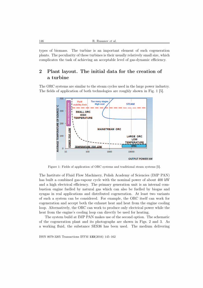
Figure 3: The combined gas/vapour (ORC) power plant: internal combustion engine from MAN(top left), heat recovery boiler (bottom left), 40 kW ORC system (right).
not only from the small scales of the systems. The fluids used in ORC plants havelarge particles which leads to large densities. Large density means small specificvolume hence small volume flow rates. The tendency of using turbines of radial-axial direction of the flow in ORC systems can be found in many publications. Allof them underline relatively high efficiencies of the small power machines [7–11].
A well described example of a 30 kW turbogenerator with a radial-axial tur-bine has been presented by Kang [7]. Figures 4 and 5 show the 3D model anda photograph of the device. The measured power and efficiency near the designpoint were found at 32.7 kW and 78.7%, respectively. It must be noted that thisis the electrical efficiency of the turbogenerator which besides the turbine internallosses takes into account the shaft and disc friction losses, mechanical losses andelectrical losses. In comparison with other small ORC turbines described in theliterature this value is considered high [12,13].
Good parameters of radial-axial stages were one of the reasons why this kindof design was applied in the case of a turbogenerator working with the SolkathermSES36 fluid at IMP PAN. This fluid is an azeotropic mixture [14], its thermody-namic parameters – both in 0D and computational fluid dynamics (CFD) sim-ulations – have been acquired from the CoolProp thermodynamic properties li-brary [15].
ISSN 0079-3205 Transactions IFFM 133(2016) 145–162

Design and performance study of a small-scale waste. . . 149149
Figure 4: A 3D model of the tur-bogenerator designed forR245fa fluid [7].
Figure 5: A photograph of the R245fa turbogen-erator [7].
4 Radial-axial single stream turbine
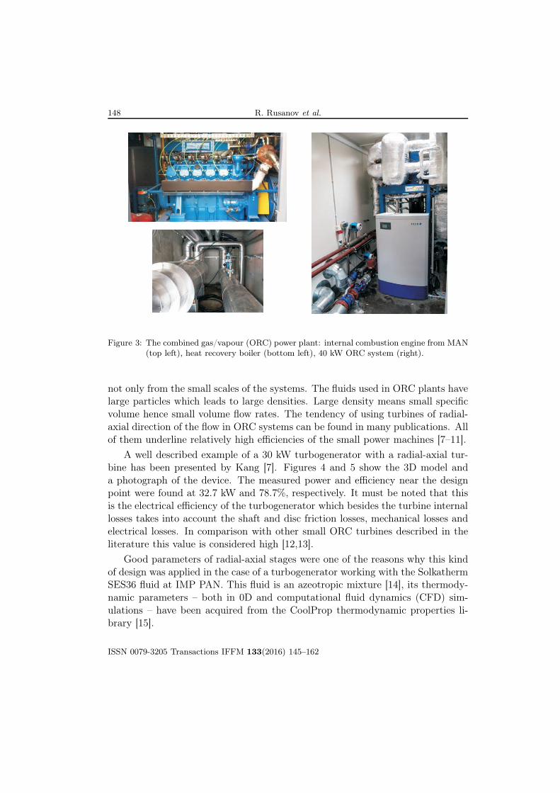
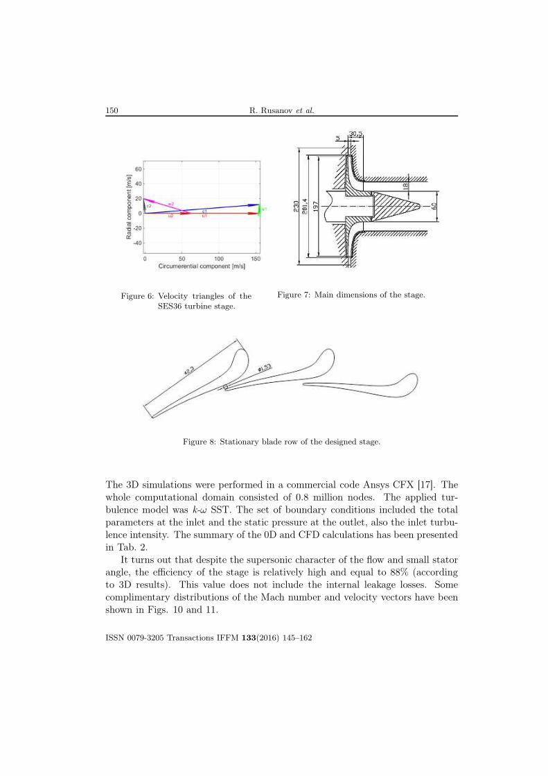
The most important design parameters of the turbine are shown in Tab. 1. Inorder to obtain a satisfying blade height at the stator a very small nozzle outflowangle α1 was set equal to 4.4 ◦. The velocity triangles for the stage have beenpresented in Fig. 6 and the main dimensions of the stage can be found in Fig. 7.The flowpath geometry was designed in the BladeGen software which belongs tothe Ansys software package [17]. The designed nozzle (Fig. 8) has a convergentgeometry despite supersonic character of the flow at the outlet. The reason forthat is a relatively low Mach number which is equal to 1.33. For these conditionsa convergent-divergent nozzle gives negligible efficiency benefit [16]. The statorand rotor assembly as a 3D model has been shown in Fig. 9.
Table 1: SES36 turbine design parameters.
Inlet pressure 1.464 MPa(abs)
Inlet temperature 414.15 K
Outlet pressure 0.22 MPa(abs)
Mass flow rate 1.22 kg/s
Rotational speed 15000 rpm
ISSN 0079-3205 Transactions IFFM 133(2016) 145–162
150 R. Rusanov et al.
Figure 6: Velocity triangles of theSES36 turbine stage.
Figure 7: Main dimensions of the stage.
Figure 8: Stationary blade row of the designed stage.
The 3D simulations were performed in a commercial code Ansys CFX [17]. Thewhole computational domain consisted of 0.8 million nodes. The applied tur-bulence model was k-ω SST. The set of boundary conditions included the totalparameters at the inlet and the static pressure at the outlet, also the inlet turbu-lence intensity. The summary of the 0D and CFD calculations has been presentedin Tab. 2.
It turns out that despite the supersonic character of the flow and small statorangle, the efficiency of the stage is relatively high and equal to 88% (accordingto 3D results). This value does not include the internal leakage losses. Somecomplimentary distributions of the Mach number and velocity vectors have beenshown in Figs. 10 and 11.
ISSN 0079-3205 Transactions IFFM 133(2016) 145–162

Design and performance study of a small-scale waste. . . 151151
Figure 9: 3D model of the rotor and stator assembly.
Table 2: Results of the performed computations, part I.
Model 0D Model 3D Number of blades Torque Rotational speed
P [kW] η [-] P [kW] η [-] stator rotor T [Nm] n [rpm]
29.4 0.86 30.2 0.88 22 15 19.23 15 000
Table 3: Results of the performed computations, part II.
Inlet Pressure Outlet Inlet Temperature Outletpressure between the pressure temperature between the temperature
blade rows blade rows
p0 [kPa] p1 [kPa] p2 [kPa] T0 [K] T1 [K] T2 [K]
1464 492 220 414.15 386.45 370.1
5 Radial-axial double stream turbine
The main disadvantage of the single stream radial-axial construction is a signif-icant axial thrust. This shortcoming is absent in the double stream turbine, inwhich the flow starting from the radial section is divided into two symmetricalaxial flows (in different directions). This kind of design can be realized in twovariants – back-to-back rotor wheels and front-to-front rotor wheels (this variant
ISSN 0079-3205 Transactions IFFM 133(2016) 145–162

152 R. Rusanov et al.
Figure 10: Relative Mach number (50% of span; left – stator, right – rotor.
Figure 11: Velocity vectors in the rotor averaged at meridional surface.
is axially longer as there must be space between the rotors to form the outlets).
Figure 12 presents a view of the flow part and Tab. 4 shows the main charac-teristics of the double stream radial-axial turbine (single side). 3D calculations ofthe designed flow part were performed using the software package IPMFlow [12].The calculation is performed on the grid with a total number of more than 1 mil-lion cells (about 500 thousand of cells in one row) using the Benedict-Webb-Rubinequation of state with 32 members [18].
Figures 13 and 14 show a visualization of the flow path, whereas Tab. 5 gathersmain integral characteristics obtained from 3D calculations. Despite the fact thatthe flow part consists of a single stage, which operates at a high thermal gradient,there is a favorable flow pattern. The maximum value of the Mach number inthe whole of the flow part is less than 2, there are no strong shocks and flowseparations. The proposed flow part has a high gas-dynamic efficiency, its internalefficiency is 88.5 %. Despite the advantageous properties of the double stream
ISSN 0079-3205 Transactions IFFM 133(2016) 145–162

Design and performance study of a small-scale waste. . . 153153
Table 4: The geometrical characteristics of the radial-axial flow part.
rin, stator rout, stator lin, stator lout, stator z, stator
100 mm 86.0 mm 3 mm 3 mm 41
rin, rotor rmid.out, rotor lin, rotor lout, rotor z, rotor
81 mm 36.3 mm 3 mm 16 mm 16
where rin – inlet radius, rout – outlet radius, rmid.out – outlet mid radius, lin – blade inlet height, lout– blade outlet height, z – number of blades.
Figure 12: Relative Mach number (x/l = 0.5); left – stator, right – rotor.
geometry the single stream variant has been selected for actual manufacturing asit is a cheaper and simpler solution.
Table 5: The main integral characteristics of the flow part.
Inlet Inlet Temperature Rotor inlet Outlet Rotor inlet Outlet Stage Stagepressure temperature between absolute absolute relative relative power efficiency
blade rows velocity velocity velocity velocity
p1 [kPa] T 1 [K] T 2 [K] c1 [m/s] c2 [m/s] w1 [m/s] w2 [m/s] P [kW] η [-]
440.5 394.67 379.77 152.1 29.9 26.7 72.8 30.1 0.885
ISSN 0079-3205 Transactions IFFM 133(2016) 145–162

154 R. Rusanov et al.
a b
Figure 13: Velocity vector and pressure contours in the average meridional section: a – stator;b – rotor.
a b
Figure 14: Velocity vector and pressure contours in the middle tangential section: a – stator;b – rotor.
6 Mechanical design
High rotational speed and significant axial thrust (reaction turbine) require anadequate bearing system [19,20]. One of the best choice would be to use oil lubri-cated slide bearings. Unfortunately, one of the design condition was a hermeticcasing in order to minimize the working fluid loss. Lubrication with oil would also
ISSN 0079-3205 Transactions IFFM 133(2016) 145–162
Design and performance study of a small-scale waste. . . 155155
require a special mechanical sealing and oil separation.Using magnetic bearings would be an option but this kind of bearing system
is the most expensive and does not pay off in a small machine. Another optionwould be to use static or dynamic (e.g. foil) bearings but the drawback of thissolution is its relatively small capacity, which in the case of a reaction turbine(significant axial thrust) requires a balancing piston. A balancing piston is a de-vice that increases the internal leakage loss and requires a longer rotor (shaft)which is particularly undesirable in an overhang design.
Some companies apply slide bearings lubricated by a liquid fraction of theworking fluid (greater capacity) but they require an additional cooling cycle inorder to avoid local boiling in the lubrication film.
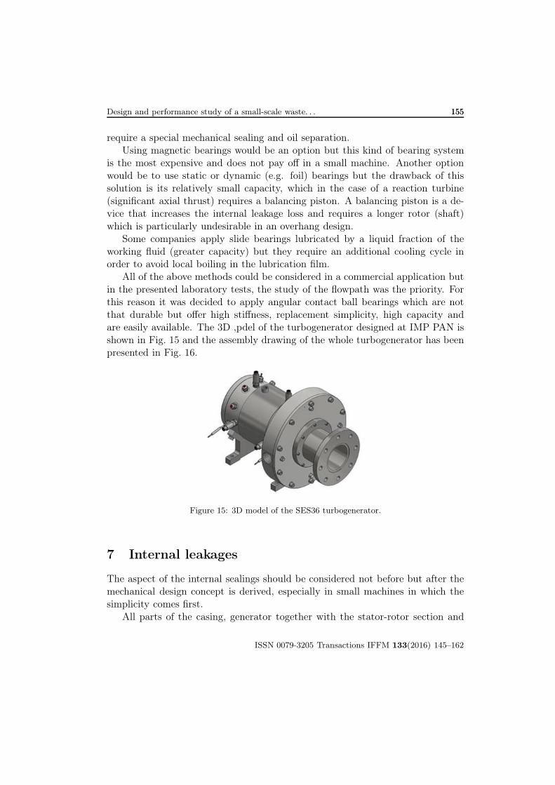
All of the above methods could be considered in a commercial application butin the presented laboratory tests, the study of the flowpath was the priority. Forthis reason it was decided to apply angular contact ball bearings which are notthat durable but offer high stiffness, replacement simplicity, high capacity andare easily available. The 3D ,pdel of the turbogenerator designed at IMP PAN isshown in Fig. 15 and the assembly drawing of the whole turbogenerator has beenpresented in Fig. 16.
Figure 15: 3D model of the SES36 turbogenerator.
7 Internal leakages
The aspect of the internal sealings should be considered not before but after themechanical design concept is derived, especially in small machines in which thesimplicity comes first.
All parts of the casing, generator together with the stator-rotor section and
ISSN 0079-3205 Transactions IFFM 133(2016) 145–162

156 R. Rusanov et al.
Figure 16: Assembly drawing of the SES 36 turbogenerator.
outlet part, were designed as a vertical split case. This type of design is more tightbut it has some limitations for sealing solution application. The axial assemblycauses that the full labyrinth sealing cannot be applied. A serial labyrinth mustbe used instead. This type of sealing with one wall smooth is much less efficientthan the full labyrinth because of the fact that kinetic energy of flow passing thegap is not fully decreased within one single sealing chamber [21].
Several variants of a serial labyrinth seal of the rotor were analysed. Moresophisticated solutions like coal sealing, abradable sealing or brush sealing werenot analysed. The outlet part of rotor shroud was specially shaped to be ableto work with labyrinth sealing. The sealing section was designed as a removablepart, mounted directly to the outlet pipe, Fig. 17. This solution gives more pos-sibilities for making any changes in the sealing method by replacing the wholeunit. All analysed variants of the rotor sealing are presented in Fig. 18.
The gap thickness was established as 0.25 mm (a radial clearance). The sin-gle labyrinth thickness is equal to 0.5 mm. A fully theoretical solution for thistype of sealing in not possible [21], therefore there are several methods that usecorrelations and data from experimental works. In general the flow through the
ISSN 0079-3205 Transactions IFFM 133(2016) 145–162

Design and performance study of a small-scale waste. . . 157157
sealing gland can be described as follows:
mn = AnΦ
√p1η1
, (1)
where: mn – steam mass flow rate through the sealing, An – effective profile ofthe gap, p1 – static pressure before the sealing section, η1 – specific volume ofsteam before the sealing section, and z – number of seals. Effective profile of thegap is defined as
An = απds , Φ = Φ
(p2p1, z
), (2)
where α – coefficient of flow in gap, d – shaft diameter, s - -nominal gap clearance.
Figure 17: Rotor serial labyrinth sealing mounted to the outlet section.
The function of pressure drop p2/p1 (p2 – pressure at the sealing outlet) includesthe information about the α coefficient of flow and it is dependent on the shapeof the labyrinth seal and the a/s ratio, where a is the distance between theseals. Figure 19 shows a chart with the flow function shapes for serial labyrinth
ISSN 0079-3205 Transactions IFFM 133(2016) 145–162

158 R. Rusanov et al.
Figure 18: Geometry of the proposed sealing rings, 3 considered variants.
Figure 19: Function of flow for the serial labyrinth sealing.
sealings, data comes from experimental research [21]. The values assumed in thecalculations and the results for different variants of seals are summarised in Tab. 6.
ISSN 0079-3205 Transactions IFFM 133(2016) 145–162

Design and performance study of a small-scale waste. . . 159159
Table 6: Parameters and values assumed during sealing calculations.
No. Value Symbol Units Variant 1 Variant 2 Variant 3 Example
1 Number of blades z – 5 11 6 12
2 Gap clearance s m 0.00025 0.00025 0.00025 0.00025
3 Distance betweenblades
a m 0.002 0.001 0.002 0.003
4 a/s ratio a/s – 8 4 8 12
5 Flow coefficient ingap
α – 0.7 0.7 0.7 0.7
6 Shaft diameter d m 0.106 0.106 0.106 0.106
7 Effective area of flow An m2 5.83×10⁻⁵ 5.83×10⁻⁵ 5.83×10⁻⁵ 5.83×10⁻⁵
8 Pressure at the seal-ing inlet
p1 Pa 492 000 492 000 492 000 492 000
9 Pressure at the seal-ing outlet
p2 Pa 220 000 220 000 220 000 220 000
10 Speciffic volumebefore sealing
ν m3/kg 0.0312 0.0312 0.0312 0.0312
11 Pressure ratio p2/p1 – 0.447 0.447 0.447 0.447
12 Square of the flowfunction value
Φ2 – 0.19 0.16 0.17 0.08
13 Flow function value Φ – 0.436 0.4 0.412 0.283
14 Mass flow of the leak mn kg/s 0.101 0.093 0.095 0.065
In each sealing geometry seals were assumed sharp. Results show similar valuesof leak. It is possible to obtain better results, to decrease the flow rate of leakbut the number of seals and the distance between them should be increased, orthe gap clearance should be decreased. More seals means that the sealing moduleand the rotor shroud would be longer. This scenario is limited by strength anddynamic conditions. It is important to realise that this method can introducesome errors into the values of flow because this algorithm is not dependent on therotor rotational speed and the real shape of the labyrinth sealing. The calculationswere verified by another method, where leakage mass flow rate is extracted directlylike for full labyrinth sealing, than a correction coefficient is introduced, suitablefor proper seal geometry [22]. The formula
G= 0.933αµγFp
√p1ν1
, (3)
takes into account geometry of the seal where: α – relative flow through thesealing, function of number of seals and inlet-outlet pressure ratio, µ – coefficient
ISSN 0079-3205 Transactions IFFM 133(2016) 145–162
160 R. Rusanov et al.
of leakage through the gap, dependent on the geometry of the seal (experimentaldata), ν – correction factor for half labyrinth sealing, function of number of sealsand the coefficient of kinetic energy utilization by steam passing through followingspaces between seals, Fp – geometrical area of the sealing gap.
The results from this algorithm are slightly different compared to the previousone and the mass flow rate is higher in each analysed case, Tab. 7. It is importantto underline that both methods are based on empirically derived factors andaveraged experimental data thus errors can be expected.
Table 7: Results from second algorithm.
Value Symbol Units Variant 1 Variant 2 Variant 3 Example
Mass flow rate mn kg/s 0.13 0.132 0.125 0.090
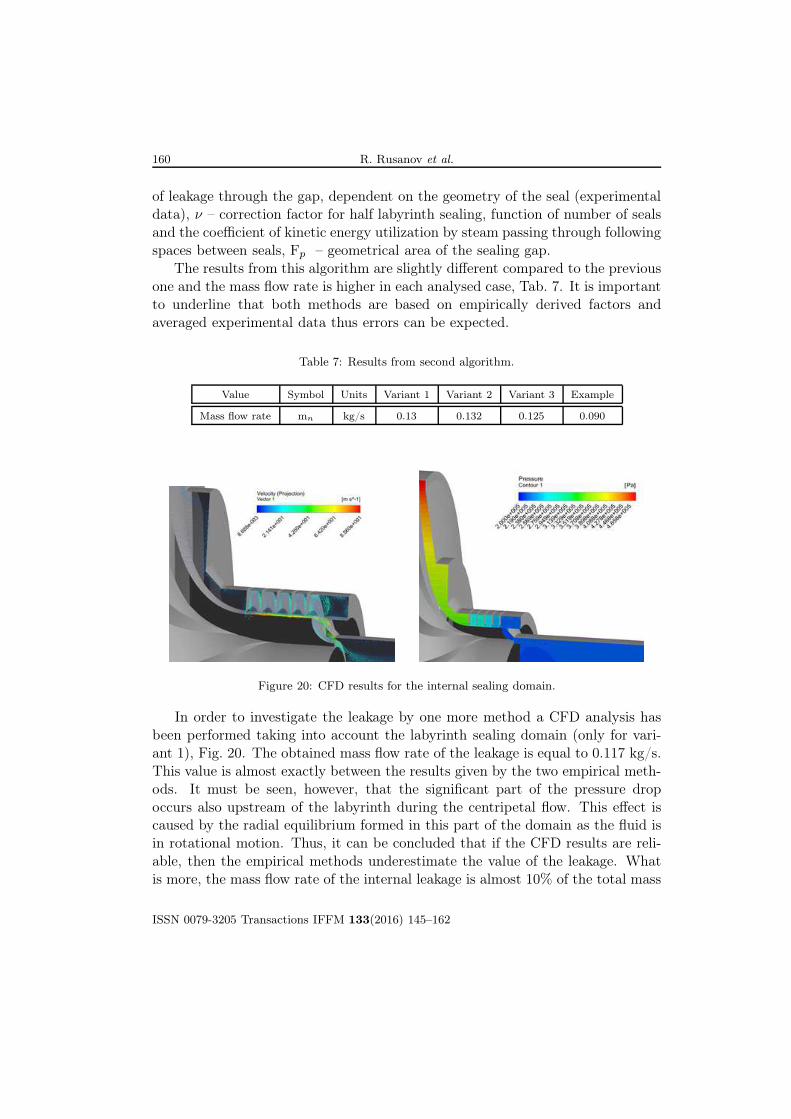
Figure 20: CFD results for the internal sealing domain.
In order to investigate the leakage by one more method a CFD analysis hasbeen performed taking into account the labyrinth sealing domain (only for vari-ant 1), Fig. 20. The obtained mass flow rate of the leakage is equal to 0.117 kg/s.This value is almost exactly between the results given by the two empirical meth-ods. It must be seen, however, that the significant part of the pressure dropoccurs also upstream of the labyrinth during the centripetal flow. This effect iscaused by the radial equilibrium formed in this part of the domain as the fluid isin rotational motion. Thus, it can be concluded that if the CFD results are reli-able, then the empirical methods underestimate the value of the leakage. Whatis more, the mass flow rate of the internal leakage is almost 10% of the total mass
ISSN 0079-3205 Transactions IFFM 133(2016) 145–162
Design and performance study of a small-scale waste. . . 161161
flow rate through the machine. It means that the work done by the fluid on therotor is almost 10% less than without the leakage and that corresponds to thesimilar drop in the efficiency.
8 Conclusions
A case study of a small turbogenerator design process has been presented. Twovariants of radial-axial turbine flowpaths working with SES 36 fluid have beenconsidered. Both variants reveal a relatively high gas dynamic efficiency equal toabout 88% in each case. However, single stream turbine is preferable because itis a simpler design, cheaper to manufacture and safer if considered from the pointof rotordynamics.
The concept of the mechanical design has been also briefly described, mainlyfrom the point of view of the bearing selection. The set of angular contact ballbearings has been selected as an advantageous option from the point of view ofa laboratory test rig.
The analysis of internal leakages has been described in more detail. It canbe seen that the internal sealing is a crucial component, especially in small ma-chines. Despite a relatively small radial clearance between the rotor and the casinglabyrinth the internal leakage is about 10% of the main flow ratio. It correspondsto a similar drop in the turbine stage efficiency. Perhaps, for small cogenerationunits more sophisticated sealing technologies could be beneficial.
Received in July 2016
References
[1] Duvia A., Gaia M.: ORC plants for power production from biomasss from 0.4 to 1.5 MWe.Technology, efficiency, practical experiences and economy. In: Proc. 7th Holzenergie Symp.,ETH Zürich 2002.
[2] Mikielewicz J., Bykuć S., Mikielewicz D.: Application of renewable energy sources to driveORC mikro CHP. In: Heat Transfer Renewable Sources of Energy (J. Mikielewicz, W.Nowak, A. Stachel, Eds.), 2006.
[3] Nowak W., Borsukiewicz-Gozdur A.: ORC power plants as a means of utilisation of energyfrom low-temperature sources. Czysta Energia 2(2011), 32–35 (in Polish).
[4] Mikielewicz J., Mikielewicz D., Ihnatowicz E., Kaczmarczyk T., Wajs J., Matysko R. etal.: Thermodynamic cycles of ORC micro power plants. Wydawnictwo IMP PAN, Gdańsk2013.
[5] Gaia M.: 30 years of organic Rankine cycle development. In: Proc. First Int. Semin. ORCPower Syst., Delft 2011.
ISSN 0079-3205 Transactions IFFM 133(2016) 145–162

162 R. Rusanov et al.
[6] Baljé O.E.: A study on design criteria and matching of turbomachines: Part A – Sim-ilarity relations and design criteria of turbines. J. Eng. Power 84(1962), 1, 83–102,DOI:10.1115/1.3673386.
[7] Kang S.H.: Design and experimental study of ORC (organic Rankine cycle) and radialturbine using R245fa working fluid. Energy 41(2012), 1, 514–524.
[8] Capata R., Hernandez G.: Preliminary design and simulation of a turbo expanderfor small rated power organic Rankine cycle (ORC). Energies 7(2014), 11, 7067–7093,DOI:10.3390/en7117067.
[9] Klonowicz P., Rusanov R., Rusanov A., Lampart P., Suchocki T., Surwiło J.: Methods fordesign of radia-axial turbines for ORC cogeneration unit working with MDM. Bull. NTU‘KhPI’. Ser. Power Heat Eng. Process. Equip. 16(2015), 67–77.
[10] Klonowicz P., Surwiło J., Witanowski Ł., Suchocki T.K., Kozanecki Z., Lampart P.: Designand numerical study of turbines operating with MDM asworking fluid. Open Eng. 5(2015),485–499, DOI:10.1515/eng-2015-0050.
[11] Suchocki T., Lampart P., Klonowicz P.: Numerical investigation of a GTM-140 turbojetengine. Zesz. Nauk. Ciepl. Masz. Przepływowe – Turbomach. / Politech. Łódzka. 145(2014),115–116.
[12] Klonowicz P., Borsukiewicz-Gozdur A., Hanausek P., Kryłłowicz W., BrüggemannD.: Design and performance measurements of an organic vapour turbine. Appl.Therm. Eng. 63(2014), 1, 297–303. http://www.sciencedirect.com/science/article/pii/S1359431113008065 (accessed Jan. 10, 2014).
[13] Harinck J., Pasquale D., Pecnik R., Colonna P.: Three-dimensional RANS simulation ofa high-speed organic Rankine cycle turbine. In: Proc. First Int. Semin. ORC Power Syst.ORC 2011, Delft 2011.
[14] Solvay, Solkatherm§SES36, http://www.solvaychemicals.com/EN/products/Fluor/SOLKANE_Specialties/SolkathermSES36.aspx.
[15] Bell I.H., Wronski J., Quoilin S., Lemort V.: Pure and pseudo-pure fluid thermophysicalproperty evaluation and the open-source thermophysical property library CoolProp. Ind. Eng.Chem. Res. 53(2014), 2498–2508, DOI:10.1021/ie4033999.
[16] Craig H.R.M., Cox H.J.A.: Performance estimation of axial flow turbines. In: Proc. Inst.Mech. Eng. 185(1970), 1, 407–424.
[17] ANSYS Academic Research, Lelease 16, 2014.
[18] Rusanov A.V., Lampart P., Rusanov R.A.: Interpolation-analytical approximation of mod-ified Benedict-Webb-Rubin equation of state for accounting of the real properties of workingfluid in 3D calculations. Compress. Energ. Mach. Build. (2014), 18–23.
[19] Kicinski J., Zywica G.: The numerical analysis of the steam microturbine rotor supportedon foil bearings. Adv. Vib. Eng. 11(2012), 2, 113–119.
[20] Zywica G., Drewczynski M., Kicinski J., Rzadkowski R.: Computational modal and strengthanalysis of the steam microturbine with fluid-film bearings. J. Vib. Eng. Technol. 2(2014),6, 543–549.
[21] Perycz S.: Steam and gas turbines. IMP PAN, Ossolineum, Wrocław 1992 (in Polish).
[22] Samojłowicz G., Trojanowski B.: Steam turbines. PWN, Warsaw 1957 (in Polish).
ISSN 0079-3205 Transactions IFFM 133(2016) 145–162