![Struktur Beton 2-P-Delta Effect [Compatibility Mode]](https://static.fdocuments.pl/doc/165x107/5695d39b1a28ab9b029e89df/struktur-beton-2-p-delta-effect-compatibility-mode.jpg)
CHATTERING-FREE SLIDING MODE VECTOR CONTROL …€¦ · Fig.3. Sliding-mode control of single-input...
14
Prace Naukowe Instytutu Maszyn, Napędów i Pomiarów Elektrycznych Nr 60 Politechniki Wroclawskiej Nr 60 Studia i Materialy Nr 27 2007 AC/DC line-side converter, PWM rectifier, Direct Power Control, Look-up Table-based Modulation, chattering-free Sliding Mode Control, smoothing integrator, nonlinear control Michal KNAPCZYK * , Krzysztof PIEŃKOWSKI * CHATTERING-FREE SLIDING MODE VECTOR CONTROL OF AC/DC LINE-SIDE REGENERATIVE CONVERTER The paper presents the analysis of the modified control strategy for the AC/DC line-side converter with the Direct Power Control strategy. The application of the chattering-free sliding-mode controller with a smoothing integrator of the DC-link voltage has been presented. The design of the Direct Power Control method for the AC/DC line-side converters is based on the cascade structure. Hence the dynamics of the line current transients is forced by the inner control loop. The dynamics of the DC-link voltage is regulated by the outer control loop which is superior to the inner one. The DC-link voltage controller produces the output values which are simultaneously the input values for the con- trollers of the inner loop. Assuming that the DC-link voltage is controlled by the fast-switching slid- ing-mode controller the chattering phenomenon has an extremely negative influence on the quality of the operation of the inner controllers and must be eliminated. The novel chattering-free sliding-mode controller of the DC-link voltage has been designed and examined. The simulation and experimental results of the presented technique achieved with the help of the 3kVA power converter with the fixed- point DSP have been demonstrated and concluded. 1. INTRODUCTION The AC/DC power conversion is used in the large majority of the industrial and gen- eral-purpose applications. The intensive and still increasing consumption of the electri- cal energy forces the need of the providing the high efficiency and reliability of the power conversion at minimum losses, distortions and disturbances. For many decades the line commutated diode and thyristor rectifiers have been successfully used in indus- try. Despite the simplicity of their construction and operation the diode and especially thyristor valve–based converters have been introducing a great amount of the lower __________ * Politechnika Wroclawska, Instytut Maszyn, Napędów i Pomiarów Elektrycznych, 50-370 Wroclaw, ul. Smoluchowskiego 19, [email protected], [email protected].
Transcript of CHATTERING-FREE SLIDING MODE VECTOR CONTROL …€¦ · Fig.3. Sliding-mode control of single-input...

Prace Naukowe Instytutu Maszyn, Napędów i Pomiarów Elektrycznych Nr 60 Politechniki Wrocławskiej Nr 60
Studia i Materiały Nr 27 2007
AC/DC line-side converter, PWM rectifier,
Direct Power Control, Look-up Table-based Modulation,
chattering-free Sliding Mode Control, smoothing integrator, nonlinear control
Michał KNAPCZYK*, Krzysztof PIEŃKOWSKI*
CHATTERING-FREE SLIDING MODE VECTOR CONTROL
OF AC/DC LINE-SIDE REGENERATIVE CONVERTER
The paper presents the analysis of the modified control strategy for the AC/DC line-side converter with the Direct Power Control strategy. The application of the chattering-free sliding-mode controller with a smoothing integrator of the DC-link voltage has been presented. The design of the Direct Power Control method for the AC/DC line-side converters is based on the cascade structure. Hence the dynamics of the line current transients is forced by the inner control loop. The dynamics of the DC-link voltage is regulated by the outer control loop which is superior to the inner one. The DC-link voltage controller produces the output values which are simultaneously the input values for the con-trollers of the inner loop. Assuming that the DC-link voltage is controlled by the fast-switching slid-ing-mode controller the chattering phenomenon has an extremely negative influence on the quality of the operation of the inner controllers and must be eliminated. The novel chattering-free sliding-mode controller of the DC-link voltage has been designed and examined. The simulation and experimental results of the presented technique achieved with the help of the 3kVA power converter with the fixed-point DSP have been demonstrated and concluded.
1. INTRODUCTION
The AC/DC power conversion is used in the large majority of the industrial and gen-eral-purpose applications. The intensive and still increasing consumption of the electri-cal energy forces the need of the providing the high efficiency and reliability of the power conversion at minimum losses, distortions and disturbances. For many decades the line commutated diode and thyristor rectifiers have been successfully used in indus-try. Despite the simplicity of their construction and operation the diode and especially thyristor valve–based converters have been introducing a great amount of the lower
__________ * Politechnika Wrocławska, Instytut Maszyn, Napędów i Pomiarów Elektrycznych, 50-370 Wrocław,
ul. Smoluchowskiego 19, [email protected], [email protected].
harmonics into the AC distribution system. Moreover the phase-controlled thyristor converters are working at the different values of the power factor, which results in the varying consumption of the reactive power. In order to minimize the negative influence of the power converter on the mains the different techniques of the harmonics reductions have been developed. In the range of the high power ratings the effective method of the reduction of the line current harmonics is the use of the multipulse rectifiers. The topol-ogy of the multipulse rectifiers is based on the series or parallel connection of the indi-vidual six-pulse three-phase rectifiers via the multiple secondary windings of the line transformer. For the applications of the low and medium rated power it is advantageous to apply the passive filters between the mains and the line commutated rectifiers for the partial reduction of the low harmonics in the line currents.
The numerous constraints of the methods of the passive filtering of the distorted line currents presented above have caused the rapid development in the elaboration of the modern power factor correctors based on the fast switched power electronics devices. The AC/DC line-side converters, called the PWM rectifiers or synchronous rectifiers interface the AC side with DC bus providing the high quality of the power conversion according to the valid EU standards (IEC 61000-3). The AC/DC line-side converters provide the sinusoidal line currents at unity power factor. There are plenty of different topologies of the PWM rectifiers that have been elaborated according to the require-ments of the particular industrial applications. The most universal topology of the syn-chronous rectifier widely used in the industry is the three-phase two-level converter that besides complying with the rules of the standards provides also the bidirectional energy flow. The feature of the energy regeneration is precious in case of the electrical braking of the rotating or rushing masses like the electrical locomotives, downhill belt convey-ors, cranes and mills. The other applications of the bidirectional AC/DC line-side con-verters are the wind mills, automotive electrical systems and the novel voltage-source converter-based high voltage direct current transmission technology (VSC-HVDC).
The high requirements for the dynamic properties of the PWM rectifiers have caused the significant development of the control techniques for the converters. Since the syn-chronous rectifiers are continually subjected to the varying line and load conditions and disturbances it is convenient to apply the nonlinear control strategies that exhibit robust-ness and better effectiveness of the rectifier’s control system. The AC/DC line-side converters represent a class of the variable structure systems (VSS) since the currents flow through the different paths depending on the present state of the power switches controlled by the control system [9]. Sliding-mode control derives from the nonlinear control strategies designed for the variable structure systems. During the closed-loop operation this kind of the nonlinear control method provides the control system insen-sitiveness to the particular extent of the uncertainties and disturbances.
This work is devoted to the design of the sliding-mode-based control of the DC-link voltage and its application into the direct power control (DPC) of the PWM rectifier. The following chapters will describe in detail the assumed methodology.

2. VOLTAGE-SOURCE AC/DC LINE-SIDE CONVERTER
The topology of the voltage-source AC/DC line-side converter is presented in Fig.1. The power circuit of the presented synchronous rectifier is based on the topol-ogy of the three-phase two-level PWM voltage-source inverter.
Fig.1. AC/DC line-side converter: a) three-phase bridge, b) equivalent phase circuit
The bridge of the PWM rectifier consists of six fully-controlled IGBT transistors connected to the grid throughout the three symmetrical line inductors. The control of the voltage drop over the line chokes provides the sinusoidal line currents. It is con-venient to describe the AC/DC line-side converter in the rectangular d-q frame rotat-ing with the angular velocity corresponding to the grid pulsation ω. Thus the dynami-cal model of the PWM rectifier is described by the equations (1).
loaddcddc
convqgqggdggqggq
convdgdggqggdggd
iudt
dCi
uiRiLidt
dLe
uiRiLidt
dLe
+=
+++=
++−=
ω
ω
(1)
where eg – grid source voltage [V], ig – line current [A], uconv – converter input volt-
age [V], Rg, Lg – resistance [Ω] and inductance [H] of the symmetrical line chokes. Assuming that the converter model is lossless and the grid voltages and currents are
sinusoidal the power balance for the PWM rectifier is described by the equation (2).
( ) ( ) dcdcgqgqgdgd iuieietp =+=2
3 (2)
3. DIRECT POWER CONTROL OF PWM RECTIFIER
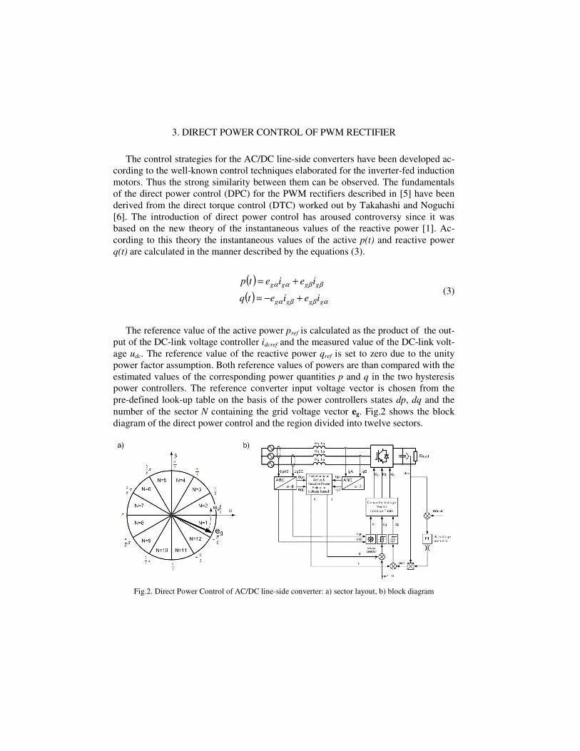
The control strategies for the AC/DC line-side converters have been developed ac-cording to the well-known control techniques elaborated for the inverter-fed induction motors. Thus the strong similarity between them can be observed. The fundamentals of the direct power control (DPC) for the PWM rectifiers described in [5] have been derived from the direct torque control (DTC) worked out by Takahashi and Noguchi [6]. The introduction of direct power control has aroused controversy since it was based on the new theory of the instantaneous values of the reactive power [1]. Ac-cording to this theory the instantaneous values of the active p(t) and reactive power q(t) are calculated in the manner described by the equations (3).
( )
( ) αββα
ββαα
gggg
gggg
ieietq
ieietp
+−=
+= (3)
The reference value of the active power pref is calculated as the product of the out-
put of the DC-link voltage controller idcref and the measured value of the DC-link volt-age udc. The reference value of the reactive power qref is set to zero due to the unity power factor assumption. Both reference values of powers are than compared with the estimated values of the corresponding power quantities p and q in the two hysteresis power controllers. The reference converter input voltage vector is chosen from the pre-defined look-up table on the basis of the power controllers states dp, dq and the number of the sector N containing the grid voltage vector eg. Fig.2 shows the block diagram of the direct power control and the region divided into twelve sectors.
Fig.2. Direct Power Control of AC/DC line-side converter: a) sector layout, b) block diagram

4. SLIDING-MODE CONTROL AND CHATTERING PHENOMENON
Recently more stress has been put on the elaboration of the nonlinear control algo-rithms for the PWM rectifiers in order to eliminate the disadvantageous influence of the variations of the line and load parameters on the converter operation. The significant advantage of the nonlinear control methods is no need for the strict knowledge about the controlled plant, the high robustness of the control system to the variations of the power circuit parameters and to the disturbances like the load changes. Sliding-mode control has become the principal nonlinear control method for the variable structure systems (VSS). A variable structure system is a dynamical system that changes the structure in function of its state and outer input variables. Fig.3 presents a control system that has the variable structure due to the application of the bang-bang controller.
Fig.3. Sliding-mode control of single-input single-output plant
The proposed sliding-mode controller consists of a two-level comparator that de-
fines the two structures of the control system depending on the control law defined by the switching function S. For the structure with u=-umax the dynamics of the system is represented by the state trajectories on the phase plane depicted in Fig.4a.
Fig.4. State trajectories of the considered system for the different signs of the control gain: a) negative only, b) positive only, c) in sliding-mode while switched at high frequency
Fig.4b presents the state trajectories for the structure with u=+umax. If the control-
ler switches the sign of the gain |u| with the suitably high frequency according to the
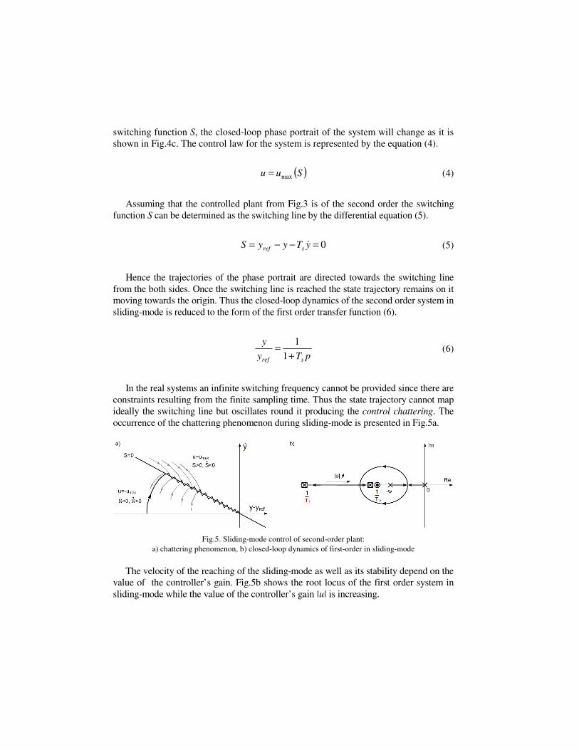
switching function S, the closed-loop phase portrait of the system will change as it is shown in Fig.4c. The control law for the system is represented by the equation (4).
( )Suu max= (4)
Assuming that the controlled plant from Fig.3 is of the second order the switching
function S can be determined as the switching line by the differential equation (5).
0=−−= yTyyS sref& (5)
Hence the trajectories of the phase portrait are directed towards the switching line
from the both sides. Once the switching line is reached the state trajectory remains on it moving towards the origin. Thus the closed-loop dynamics of the second order system in sliding-mode is reduced to the form of the first order transfer function (6).
pTy
y
sref +=
1
1 (6)
In the real systems an infinite switching frequency cannot be provided since there are
constraints resulting from the finite sampling time. Thus the state trajectory cannot map ideally the switching line but oscillates round it producing the control chattering. The occurrence of the chattering phenomenon during sliding-mode is presented in Fig.5a.
Fig.5. Sliding-mode control of second-order plant: a) chattering phenomenon, b) closed-loop dynamics of first-order in sliding-mode
The velocity of the reaching of the sliding-mode as well as its stability depend on the
value of the controller’s gain. Fig.5b shows the root locus of the first order system in sliding-mode while the value of the controller’s gain |u| is increasing.
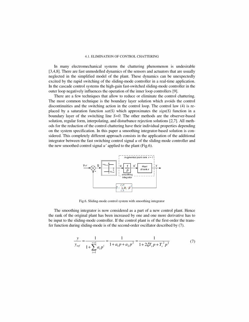
4.1. ELIMINATION OF CONTROL CHATTERING
In many electromechanical systems the chattering phenomenon is undesirable [3,4,8]. There are fast unmodelled dynamics of the sensors and actuators that are usually neglected in the simplified model of the plant. These dynamics can be unexpectedly excited by the rapid switching of the sliding-mode controller in a real-time application. In the cascade control systems the high-gain fast-switched sliding-mode controller in the outer loop negatively influences the operation of the inner loop controllers [9].
There are a few techniques that allow to reduce or eliminate the control chattering. The most common technique is the boundary layer solution which avoids the control discontinuities and the switching action in the control loop. The control law (4) is re-placed by a saturation function sat(S) which approximates the sign(S) function in a boundary layer of the switching line S=0. The other methods are the observer-based solution, regular form, interpolating, and disturbance rejection solutions [2,7]. All meth-ods for the reduction of the control chattering have their individual properties depending on the system specification. In this paper a smoothing integrator-based solution is con-sidered. This completely different approach consists in the application of the additional integrator between the fast switching control signal u of the sliding-mode controller and the new smoothed control signal u’ applied to the plant (Fig.6).
Fig.6. Sliding-mode control system with smoothing integrator
The smoothing integrator is now considered as a part of a new control plant. Hence
the rank of the original plant has been increased by one and one more derivative has to be input to the sliding-mode controller. If the control plant is of the first-order the trans-fer function during sliding-mode is of the second-order oscillator described by (7).
22221
1
1
21
1
1
1
1
1
pTpTpapapa
y
y
ss
r
i
ii
ref ++=
++=
+
=
∑+
=
ξ (7)
5. CHATTERING-FREE SLIDING-MODE CONTROL OF DC-LINK VOLTAGE
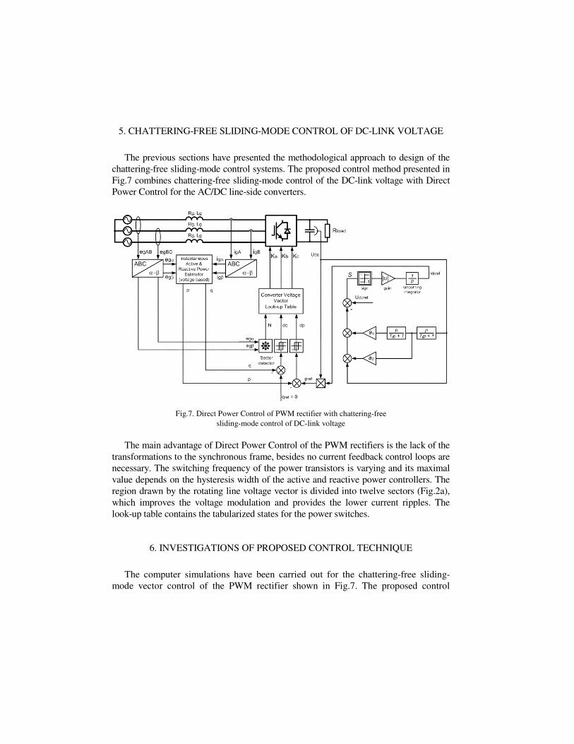
The previous sections have presented the methodological approach to design of the chattering-free sliding-mode control systems. The proposed control method presented in Fig.7 combines chattering-free sliding-mode control of the DC-link voltage with Direct Power Control for the AC/DC line-side converters.
Fig.7. Direct Power Control of PWM rectifier with chattering-free sliding-mode control of DC-link voltage
The main advantage of Direct Power Control of the PWM rectifiers is the lack of the
transformations to the synchronous frame, besides no current feedback control loops are necessary. The switching frequency of the power transistors is varying and its maximal value depends on the hysteresis width of the active and reactive power controllers. The region drawn by the rotating line voltage vector is divided into twelve sectors (Fig.2a), which improves the voltage modulation and provides the lower current ripples. The look-up table contains the tabularized states for the power switches.
6. INVESTIGATIONS OF PROPOSED CONTROL TECHNIQUE
The computer simulations have been carried out for the chattering-free sliding-mode vector control of the PWM rectifier shown in Fig.7. The proposed control

method has been tested using Matlab/Simulink. The simulation model has been di-vided into two subsystems which have been computed with different rates. Hence the reliable analysis of the PWM rectifier’s model and its discrete control system has been performed. The main parameters of the simulation model are presented in Tab.1.
Tab.1 Parameters of the simulation model
Source phase voltage eg: 230 V
Source voltage frequency fg: 50 Hz
Line choke resistance Rg: 100 mΩ
Line choke inductance Lg: 11 mH
DC-link capacitance Cd: 1000 µF
DC-link nominal voltage Udc: 600 V
Nominal load resistance Rload: 100 Ω
PWM rectifier sampling time Tp1: 1 µs
Control system sampling time Tp2: 35 µs
The control algorithm has been verified experimentally with help of the laboratory
setup with the AC/DC converter presented in Fig.8. The power unit of the AC/DC con-verter is based on the 3.3 kW IGBT power module by EUPEC® with the electronic interface EiceDRIVER™ 6ED003E06-F. For the realization of the control tasks in the experimental setup of the AC/DC converter the evaluation board eZdsp™ R2812 by Spectrum Digital® based on the 150 MHz TMX320R2812 Digital Signal Processor by Texas Instruments® has been chosen.
Fig.8. Overview of laboratory setup
The AC/DC converter requires the exact information about all necessary state vari-
ables. The position of the grid voltage vector must be currently computed to provide the correct synchronization of the line current vector. In the proposed control system of the PWM rectifier the voltage and current LEM transducers have been applied.
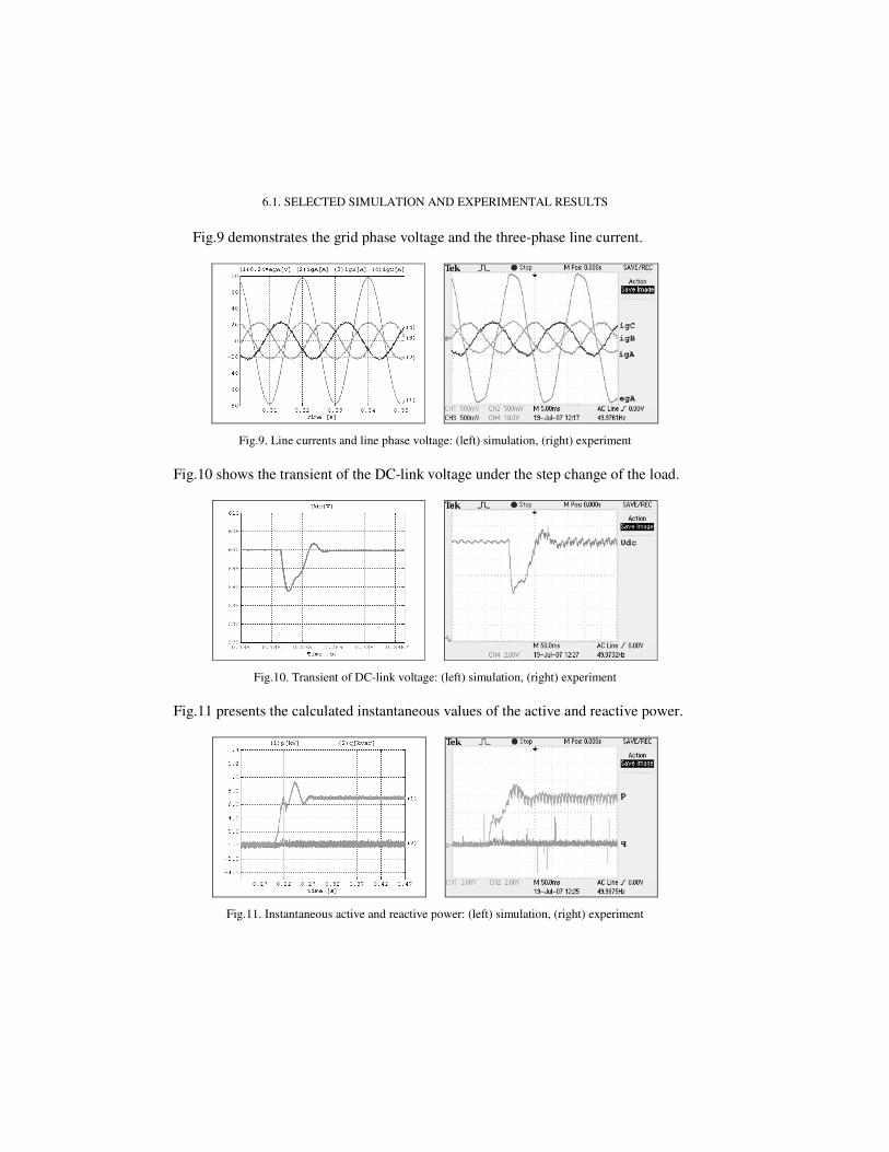
6.1. SELECTED SIMULATION AND EXPERIMENTAL RESULTS
Fig.9 demonstrates the grid phase voltage and the three-phase line current.
Fig.9. Line currents and line phase voltage: (left) simulation, (right) experiment
Fig.10 shows the transient of the DC-link voltage under the step change of the load.
Fig.10. Transient of DC-link voltage: (left) simulation, (right) experiment
Fig.11 presents the calculated instantaneous values of the active and reactive power.
Fig.11. Instantaneous active and reactive power: (left) simulation, (right) experiment
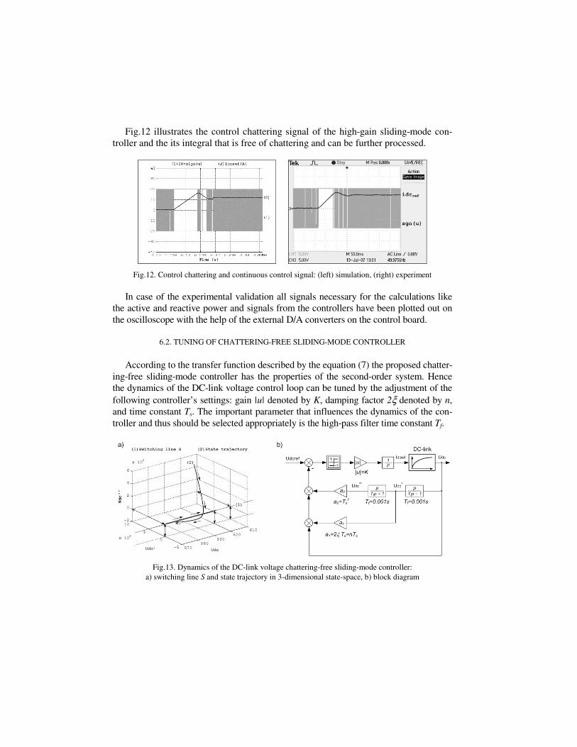
Fig.12 illustrates the control chattering signal of the high-gain sliding-mode con-troller and the its integral that is free of chattering and can be further processed.
Fig.12. Control chattering and continuous control signal: (left) simulation, (right) experiment
In case of the experimental validation all signals necessary for the calculations like
the active and reactive power and signals from the controllers have been plotted out on the oscilloscope with the help of the external D/A converters on the control board.
6.2. TUNING OF CHATTERING-FREE SLIDING-MODE CONTROLLER
According to the transfer function described by the equation (7) the proposed chatter-ing-free sliding-mode controller has the properties of the second-order system. Hence the dynamics of the DC-link voltage control loop can be tuned by the adjustment of the following controller’s settings: gain |u| denoted by K, damping factor 2ξ denoted by n, and time constant Ts. The important parameter that influences the dynamics of the con-troller and thus should be selected appropriately is the high-pass filter time constant Tf.
Fig.13. Dynamics of the DC-link voltage chattering-free sliding-mode controller: a) switching line S and state trajectory in 3-dimensional state-space, b) block diagram

Fig.13a presents the state trajectory during sliding-mode reaching the switching line S located in the 3-dimensional state space determined by the values of udc and its first and second time derivatives udc’ and udc”. The block diagram of the DC-link voltage sliding-mode-based control loop with the tunable parameters is depicted in Fig.13b.
The tuning of the chattering-free sliding-mode DC-link voltage controller has been carried out by the adjustment of the one of the controller settings while the values of the other parameters are strictly defined and invariable.
Fig.14 illustrates the influence of the adjustment of the individual controller settings on the dynamics of the DC-link voltage control loop. The high value of the gain K short-ens the time of the overlapping of the measured DC-link voltage with its reference and in result decreases the voltage drop during transient. On the other hand the further in-creasing of the controller’s gain K worsens the THD ratio of the line currents.
Fig.14. DC-link voltage dynamics adjustment via tuning of: a) gain K, b) damping factor n, c) time constant Ts, d) time constant Tf
The value of the damping factor n should be appropriately selected in order to
avoid an overshoot of the DC-link voltage by the load variations. The proper value of the damping factor n provides the asymptotical transient of the DC-link voltage. The
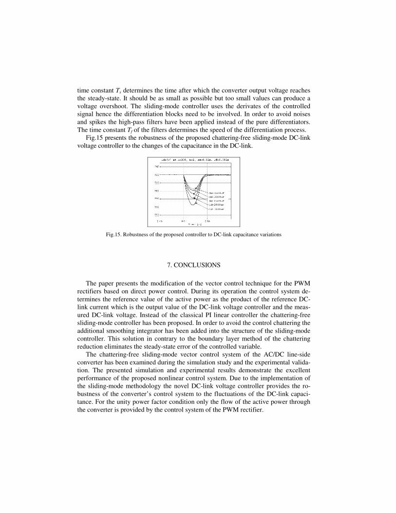
time constant Ts determines the time after which the converter output voltage reaches the steady-state. It should be as small as possible but too small values can produce a voltage overshoot. The sliding-mode controller uses the derivates of the controlled signal hence the differentiation blocks need to be involved. In order to avoid noises and spikes the high-pass filters have been applied instead of the pure differentiators. The time constant Tf of the filters determines the speed of the differentiation process.
Fig.15 presents the robustness of the proposed chattering-free sliding-mode DC-link voltage controller to the changes of the capacitance in the DC-link.
Fig.15. Robustness of the proposed controller to DC-link capacitance variations
7. CONCLUSIONS
The paper presents the modification of the vector control technique for the PWM rectifiers based on direct power control. During its operation the control system de-termines the reference value of the active power as the product of the reference DC-link current which is the output value of the DC-link voltage controller and the meas-ured DC-link voltage. Instead of the classical PI linear controller the chattering-free sliding-mode controller has been proposed. In order to avoid the control chattering the additional smoothing integrator has been added into the structure of the sliding-mode controller. This solution in contrary to the boundary layer method of the chattering reduction eliminates the steady-state error of the controlled variable.
The chattering-free sliding-mode vector control system of the AC/DC line-side converter has been examined during the simulation study and the experimental valida-tion. The presented simulation and experimental results demonstrate the excellent performance of the proposed nonlinear control system. Due to the implementation of the sliding-mode methodology the novel DC-link voltage controller provides the ro-bustness of the converter’s control system to the fluctuations of the DC-link capaci-tance. For the unity power factor condition only the flow of the active power through the converter is provided by the control system of the PWM rectifier.

REFERENCES
[1] AKAGI H., KANAZAWA Y., NABAE A., Generalized theory of the instantaneous reactive power in
three-phase circuits, IEEE International Power Electronics Conference IPEC 1983, Tokyo 1983. [2] DODDS S. J., Interpolating Sliding Mode Control: an approach to high precision platform control
with uncertain dynamics, IEE Colloquium on High Accuracy Platform Control in Space, London, June 1993.
[3] HRASKO M., VITTEK J., HAVRILA R., LOKSENINEC I., Rotor Flux Observer in Pseudo-Sliding
Mode for Vector Controlled Induction Motor Drives, 12th International Power Electronics and Mo-tion Control Conference EPE-PEMC 2006, Portorož, August/September 2006.
[4] LOUKIANOV A. G., DODDS S. J., HOSNY W., VITTEK J., A robust automotive controller design, IEEE International Conference on Control Applications, Hartford, October 1997.
[5] OHNISHI T., Three-phase PWM converter/inverter by means of instantaneous active and reactive
power control, International Conference on Industrial Electronics, Control and Instrumentation IECON 1991, Kobe, October/November 1991.
[6] TAKAHASHI I., NOGUCHI T., A new quick response and high efficiency control strategy of an
induction motor, IEEE IAS Annual Meeting, 1985. [7] UTKIN V., GULDNER J., SHI J., Sliding Mode Control in Electromechanical Systems, Taylor &
Francis, 1999. [7] WANG J., BAILEY W. N., DODDS S. J., A new sliding mode approach to the
robust control of robotic manipulators with dynamic uncertainties, IEEE International Conference on Robotics and Automation, San Diego, May 1994.
[8] WANG J., BAILEY W. N., DODDS S. J., A new sliding mode approach to the robust control of
robotic manipulators with dynamic uncertainties, IEEE International Conference on Robotics and Automation, San Diego, May 1994.
[9] YOUNG K. D., UTKIN V., ÖZGÜNER Ü., A Control Engineer’s Guide to Sliding Mode Control, IEEE Transactions on Control Systems Technology, vol.7, no.3, May 1999.
ŚLIZGOWE STEROWANIE WEKTOROWE PRZEKSZTAŁTNIKIEM SIECIOWYM AC/DC Z OGRANICZENIEM ZJAWISKA CHATTERINGU
Artykuł prezentuje zastosowanie zmodyfikowanej metody bezpośredniego sterowania mocą (DPC) przekształtnika sieciowego AC/DC o dwukierunkowym przepływie energii. Zaprojektowano układ sterowania ślizgowego w pętli regulacji napięcia wyjściowego przekształtnika. Układ sterowania przekształtnika sieciowego AC/DC w oparciu o metodę bezpośredniego sterowania mocą charakteryzuje się strukturą kaskadową. Oznacza to, że szybkie zmiany dynamiczne prądów sieciowych sterowane są w wewnętrznej pętli regulacji, natomiast regulacja napięcia stałego obwodu pośredniczącego realizowana jest w nadrzędnej pętli sterowania. Wówczas sygnał wyjściowy regulatora napięcia stałego jest sygnałem zadanym dla regulatorów prądu w wewnętrznej strukturze sterowania. Klasyczny regulator ślizgowy, charakteryzujący się szybkim przełączaniem znaku sygnału o dużej wartości wzmocnienia, zastosowany w pętli regulacji napięcia stałego obwodu pośredniczącego powoduje silne odkształcenia w przebiegach prądów sieciowych, prowadząc często do niestabilności układu sterowania przekształtnika. W tym przypadku zjawisko szybkich przełączeń sygnału sterującego, zwane chatteringiem powinno być eliminowane. Zaimplementowano metodę ograniczenia niekorzystnego zjawiska chatteringu opartą na zastosowaniu dodatkowego integratora wygładzającego przebieg nieciągłego sygnału sterującego dwustanowego regulatora ślizgowego. Przedstawiono i omówiono wybrane wyniki badań symulacyjnych i eksperymentalnych zaproponowanego układu sterowania nieliniowego przekształtnikiem sieciowym AC/DC.