ARCHIVES OF METALLURGY AND MATERIALS DOI: … · 2015-10-29 · Parametry charakteryzujące...
10
A R C H I V E S O F M E T A L L U R G Y A N D M A T E R I A L S Volume 60 DOI: 10.1515/amm-2015-0398 Issue 3 2015 M. ZIĘTALA* # , T. DUREJKO*, M. ŁAZIŃSKA* WIRE ELECTRICAL DISCHARGE MACHINING OF FEAL INTERMETALLIC SINTERS WITHOUT AND WITH ADDITION OF NANO-Al 2 O 3 OXIDE CERAMIC OBRÓBKA ELEKTROEROZYJNA SPIEKÓW NA OSNOWIE FAZY MIĘDZYMETALICZNEJ FEAL BEZ I Z DODATKIEM NANOCERAMIKI Al 2 O 3 The influence of the parameters of wire electrical discharge machining (WEDM) on the surface layer of FeAl based sinters with and without Al 2 O 3 nanoceramic addition has been studied in this paper. The properties of the sinters surface layer were con- trolled by WEDM parameters, including time of interval (t p ) and amplitude of current (I A ). The WEDM roughing and finishing treatments were carried out for selected technological parameters of process. The surface texture (ST) of the sinters after WEDM was analyzed by profilometer method. Theoretical parameters describing abrasive wear resistance of investigated sinters were estimated on the basis on the load capacity curve. On the basis on obtained results it can be stated that there is possibility of shaping geometry of nano-Al 2 O 3 doped and undoped FeAl sinters by WEDM. Reduction of the time of interval (t p ) and increase of current amplitude (I A ) during WEDM deteriorate surface properties. Addition of nano-Al 2 O 3 improve the quality of the obtained surface. Applied parameters of WEDM improve theoretical abrasive wear resistance and lubricant maintenance of the nanoceramic doped material in comparison with undoped sinter. Keywords: surface texture (ST), abrasive wear resistance, wire electrical discharge machining (WEDM), FeAl intermetallic, nano-Al 2 O 3 addition W niniejszej pracy analizowano wpływ parametrów cięcia elektrozyjnego (ang. WEDM – wire electrical discharge machining) na warstwę wierzchnią spieków na osnowie fazy międzymetalicznej FeAl bez i z dodatkiem nanoceremiki Al 2 O 3 . Poprzez zmianę parametrów obróbki elektroerozyjnej, tj. czas przerwy (t p ) i natężenie prądu (I A ), sterowano właściwościami warstwy wierzchniej obrabianych spieków. Dla wybranych parametrów technologicznych procesu przeprowadzono obróbkę zgrubną i wykańczającą. Strukturę geometryczną powierzchni (SGP) spieków po obróbce elektroerozyjnej analizowano za pomocą metody profilometrycz- nej. Parametry charakteryzujące teoretyczną odporność na zużycie ścierne zostały oszacowane na podstawie krzywych nośności Abbotta-Firestone’a. Na podstawie uzyskanych wyników stwierdzono, że istnieje możliwość kształtowania geometrii spieków FeAl bez i z dodatkiem nanoceramiki Al 2 O 3 za pomocą obróbki elektroerozyjnej WEDM. Wraz ze skróceniem czasu przerwy i wzrostem natężenia prądu podczas obróbki wzrasta chropowatość obrabianych powierzchni, natomiast dodatek nanoceramiki poprawia jakość otrzymanych powierzchni. Zastosowane parametry obróbki WEDM poprawiły teoretyczną odporność na zużycie ścierne i zdolność do przechowy- wania środka smarnego powierzchni spieków domieszkowanych nanoceramiką, w porównaniu do materiału niedomieszkowanego. 1. Introduction One of the alternative method of shaping the geometry of machines components is the electrical discharge machin- ing (EDM), currently used in the aerospace and automotive industries. This technology allows obtaining elements with complex geometry and with precisely shaped surface texture (ST) due to proper selection of such processing parameters as: * DEPARTMENT OF ADVANCED MATERIALS AND TECHNOLOGY, MILITARY UNIVERSITY OF TECHNOLOGY, 2 KALISKIEGO STR., 00-908 WARSAW, POLAND # Corresponding author: [email protected] amplitude, time of impulse or interval time [1-3]. The process of electrical discharge machining allows controlling of geom- etry and surface texture of the surface layer, determined by its application features. EDM can be applied to elements made of any electrically conductive material, regardless of their strength and hardness. Kind of processed material has only influence on the selection of technological parameters, which in turn affects the efficiency and intensity of erosion wear. The erosion-based
Transcript of ARCHIVES OF METALLURGY AND MATERIALS DOI: … · 2015-10-29 · Parametry charakteryzujące...
A R C H I V E S O F M E T A L L U R G Y A N D M A T E R I A L S
Volume 60
DOI: 10.1515/amm-2015-0398
Issue 32015
M. ZIĘTALA*#, T. DUREJKO*, M. ŁAZIŃSKA*
WIRE ELECTRICAL DISCHARGE MACHINING OF FEAL INTERMETALLIC SINTERS WITHOUT AND WITH ADDITION OF NANO-Al2O3 OXIDE CERAMIC
OBRÓBKA ELEKTROEROZYJNA SPIEKÓW NA OSNOWIE FAZY MIĘDZYMETALICZNEJ FEAL BEZ I Z DODATKIEM NANOCERAMIKI Al2O3
The influence of the parameters of wire electrical discharge machining (WEDM) on the surface layer of FeAl based sinters with and without Al2O3 nanoceramic addition has been studied in this paper. The properties of the sinters surface layer were con-trolled by WEDM parameters, including time of interval (tp) and amplitude of current (IA). The WEDM roughing and finishing treatments were carried out for selected technological parameters of process. The surface texture (ST) of the sinters after WEDM was analyzed by profilometer method. Theoretical parameters describing abrasive wear resistance of investigated sinters were estimated on the basis on the load capacity curve.
On the basis on obtained results it can be stated that there is possibility of shaping geometry of nano-Al2O3 doped and undoped FeAl sinters by WEDM. Reduction of the time of interval (tp) and increase of current amplitude (IA) during WEDM deteriorate surface properties. Addition of nano-Al2O3 improve the quality of the obtained surface. Applied parameters of WEDM improve theoretical abrasive wear resistance and lubricant maintenance of the nanoceramic doped material in comparison with undoped sinter.
Keywords: surface texture (ST), abrasive wear resistance, wire electrical discharge machining (WEDM), FeAl intermetallic, nano-Al2O3 addition
W niniejszej pracy analizowano wpływ parametrów cięcia elektrozyjnego (ang. WEDM – wire electrical discharge machining) na warstwę wierzchnią spieków na osnowie fazy międzymetalicznej FeAl bez i z dodatkiem nanoceremiki Al2O3. Poprzez zmianę parametrów obróbki elektroerozyjnej, tj. czas przerwy (tp) i natężenie prądu (IA), sterowano właściwościami warstwy wierzchniej obrabianych spieków. Dla wybranych parametrów technologicznych procesu przeprowadzono obróbkę zgrubną i wykańczającą. Strukturę geometryczną powierzchni (SGP) spieków po obróbce elektroerozyjnej analizowano za pomocą metody profilometrycz-nej. Parametry charakteryzujące teoretyczną odporność na zużycie ścierne zostały oszacowane na podstawie krzywych nośności Abbotta-Firestone’a.
Na podstawie uzyskanych wyników stwierdzono, że istnieje możliwość kształtowania geometrii spieków FeAl bez i z dodatkiem nanoceramiki Al2O3 za pomocą obróbki elektroerozyjnej WEDM. Wraz ze skróceniem czasu przerwy i wzrostem natężenia prądu podczas obróbki wzrasta chropowatość obrabianych powierzchni, natomiast dodatek nanoceramiki poprawia jakość otrzymanych powierzchni. Zastosowane parametry obróbki WEDM poprawiły teoretyczną odporność na zużycie ścierne i zdolność do przechowy-wania środka smarnego powierzchni spieków domieszkowanych nanoceramiką, w porównaniu do materiału niedomieszkowanego.
1. Introduction
One of the alternative method of shaping the geometry of machines components is the electrical discharge machin-ing (EDM), currently used in the aerospace and automotive industries. This technology allows obtaining elements with complex geometry and with precisely shaped surface texture (ST) due to proper selection of such processing parameters as:
* DEPARTMENT OF ADVANCED MATERIALS AND TECHNOLOGY, MILITARY UNIVERSITY OF TECHNOLOGY, 2 KALISKIEGO STR., 00-908 WARSAW, POLAND
# Corresponding author: [email protected]
amplitude, time of impulse or interval time [1-3]. The process of electrical discharge machining allows controlling of geom-etry and surface texture of the surface layer, determined by its application features. EDM can be applied to elements made of any electrically conductive material, regardless of their strength and hardness. Kind of processed material has only influence on the selection of technological parameters, which in turn affects the efficiency and intensity of erosion wear. The erosion-based
2448
shaping technique of machine components is also used for processing of metal matrix composites [3-6]. A main obstacle in introducing traditional machining methods to processing of these materials is reinforcement phase in the form of particles, fibers or precipitates [5]
Results of several years of research conducted in Depart-ment of Advanced Materials and Technologies of MUT have revealed that the use of electrical discharge machining with nu-merically controlled wire cutter (WEDM) allows shaping of such materials as FeAl intermetallic alloys [7].These alloys belong to group of materials which can be applied at high temperature, close to their melting points with simultaneously meeting in-creasing requirements stated by designers and engineers – high wear resistance and very good resistance to high-temperature corrosion [8-10]. However a high brittleness and a low creep resistance of Fe-Al based alloys effectively limit area of their applications. These materials can be produced by a conventional melting and casting, but finally obtained coarse-grained struc-ture required further multivariant thermo-mechanical treatment [11-14]. Nowadays, Fe-Al intermetallics are usually used as a protective coatings deposited by a detonation gas spraying [15-24] and a laser cladding [25-28]) or as reactive, exothermic mixtures (consisted of Fe and Al elemental powder) for joining other materials (e.g. in the form of thin foils) [29]. A chance for manufacturing a bulk FeAl intermetallics parts could be an ap-ply techniques based on metallurgy of technically pure iron and aluminum powders [30-32] or an implementation of a laser de-position method to produce a FeAl/metal gradient structure [33].
It was also previously shown, that doping with alumina particles has beneficial effect on high temperature behaviour of these alloys [34-36]. Refinement and strengthening of structure by alumina ceramics particles allow controlling properties of FeAl alloys, especially in the field of their high temperature applications (e.g. increase of creep resistance). Due to presence of oxide ceramic (with high abrasive wear resistance), abnormal increase of yield strength with rising temperature and lower co-hesive strength in the grain boundaries than for as cast materials, these alloys are classified as hard to machine materials [1,37,38]. These features effectively reduce or eliminate possibility of using conventional machining methods (such as turning, milling, etc.) to FeAl intermetallic sinters. The chance for commercial form-ing of semi-finished products made of these alloys is electrical discharge machining. The application of electrical discharge machining with a numerically controlled wire cutter (WEDM) allows obtaining elements with complex geometry (2,5D) and with a precisely shaped surface texture (ST) of finished product. Recently, WEDM is used to machine a wide variety of miniature and micro-parts from metals [39-40], sintered materials, alloys [41], cemented carbides and ceramics [42-43]. Therefore, the treatment of this type should enable the development of both the geometry and the surface texture of FeAl intermetallic sinters with and without the addition of nano-Al2O3 ceramics.
In present work, the result of the parameters selection for electrical discharge machining roughing and finishing of FeAl sinters doped and non-doped nano-Al2O3 have been presented.
Selection of WEDM treatment parameters allows controlling surface texture features and theoretical assessment of the abra-sive wear.
2. Investigated material
The investigated material was obtained in the sintering pro-cess at low pressure (10–2 mBar) at 1050°C and under a constant load of 40 MPa. The feedstock material was a mixture of techni-cally pure aluminum and Fe-nano-Al2O3 composite powder (2% vol. addition of nano-Al2O3 ceramic, obtained by low-energetic milling in a Fritsch ball-mill with a velocity of 200 rpm and milling time of 20 minutes [44] or mixture of technically pure aluminum and iron. Both variants have been prepared in 60 to 40 at.% iron to aluminum ratio. After pre-sintering process sinters were homogenized by annealing process at 1200°C for 1 hour in an argon atmosphere.
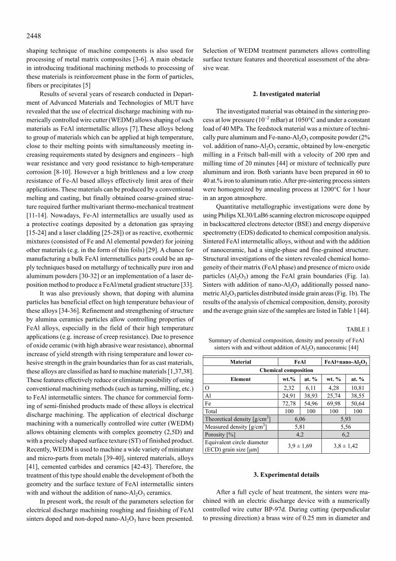
Quantitative metallographic investigations were done by using Philips XL30/LaB6 scanning electron microscope equipped in backscattered electrons detector (BSE) and energy dispersive spectrometry (EDS) dedicated to chemical composition analysis. Sintered FeAl intermetallic alloys, without and with the addition of nanoceramic, had a single-phase and fine-grained structure. Structural investigations of the sinters revealed chemical homo-geneity of their matrix (FeAl phase) and presence of micro oxide particles (Al2O3) among the FeAl grain boundaries (Fig. 1a). Sinters with addition of nano-Al2O3 additionally possed nano-metric Al2O3 particles distributed inside grain areas (Fig. 1b). The results of the analysis of chemical composition, density, porosity and the average grain size of the samples are listed in Table 1 [44].
TABLE 1
Summary of chemical composition, density and porosity of FeAl sinters with and without addition of Al2O3 nanoceramic [44]
Material FeAl FeAl+nano-Al2O3
Chemical compositionElement wt.% at. % wt. % at. %
O 2,32 6,11 4,28 10,81Al 24,91 38,93 25,74 38,55Fe 72,78 54,96 69,98 50,64Total 100 100 100 100Theoretical density [g/cm3] 6,06 5,93Measured density [g/cm3] 5,81 5,56Porosity [%] 4,2 6,2Equivalent circle diameter (ECD) grain size [μm] 3,9 ± 1,69 3,8 ± 1,42
3. Experimental details
After a full cycle of heat treatment, the sinters were ma-chined with an electric discharge device with a numerically controlled wire cutter BP-97d. During cutting (perpendicular to pressing direction) a brass wire of 0.25 mm in diameter and
2449
tensile strength of 500 MPa was used. The operating conditions were controlled by the duration of the interval between impulses tp and current amplitude IA. For selected couples of processing pa-rameters (time interval – current amplitude) roughing treatment was done, during which the FeAl samples were cut. Moreover, then finishing treatment consisting of four sparking passes was done (without surface wire penetration).
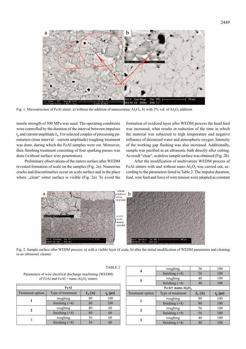
Preliminary observations of the sinters surface after WEDM revealed formation of scale on the samples (Fig. 2a). Numerous cracks and discontinuities occur on scale surface and in the place where „clean“ sinter surface is visible (Fig. 2a). To avoid the
formation of oxidized layer after WEDM process the head feed was increased, what results in reduction of the time in which the material was subjected to high temperature and negative influence of deionized water and atmospheric oxygen. Intensity of the working gap flushing was also increased. Additionally, sample was purified in an ultrasonic bath directly after cutting. As result “clear”, scaleless sample surface was obtained (Fig. 2b).
After the modification of multivariate WEDM process of FeAl sinters with and without nano-Al2O3 was carried out, ac-cording to the parameters listed in Table 2. The impulse duration, feed, wire feed and force of wire tension were adopted as constant
Fig. 1. Microstructure of FeAl sinter: a) without the addition of nanoceramic Al2O3, b) with 2% vol. of Al2O3 addition
Fig. 2. Sample surface after WEDM process: a) with a visible layer of scale, b) after the initial modification of WEDM parameters and cleaning in an ultrasonic cleaner
TABLE 2
Parameters of wire electrical discharge machining (WEDM) of FeAl and FeAl + nano-Al2O3 sinters
FeAlTreatment option Type of treatment IA [A] tp [μs]
1 roughing 80 100fi nishing (×4) 80 100
2 roughing 80 60fi nishing (×4) 80 60
3 roughing 56 60fi nishing (×4) 56 60
4 roughing 56 100fi nishing (×4) 56 100
5 roughing 40 100fi nishing (×4) 40 100FeAl+ nano-Al2O3
Treatment option Type of treatment IA [A] tp [μs]
1 roughing 80 100fi nishing (×4) 80 100
2 roughing 56 100fi nishing (×4) 56 100
3 roughing 40 100fi nishing (×4) 40 100
2450
parameters. For undoped FeAl sintered material WEDM trials were carried out by 10 variants (Tab. 2). Based on the analysis of influence of the parameters of applied electroerosion treatment for undoped FeAl sinters, 6 variants of WEDM for materials doped with 2% vol. nano-Al2O3 were selected (Tab. 2).
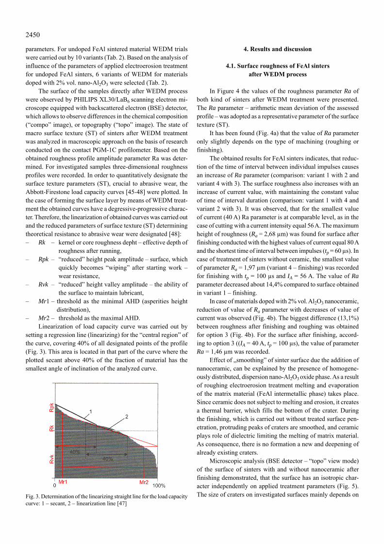
The surface of the samples directly after WEDM process were observed by PHILIPS XL30/LaB6 scanning electron mi-croscope equipped with backscattered electron (BSE) detector, which allows to observe differences in the chemical composition (“compo” image), or topography (“topo” image). The state of macro surface texture (ST) of sinters after WEDM treatment was analyzed in macroscopic approach on the basis of research conducted on the contact PGM-1C profilometer. Based on the obtained roughness profile amplitude parameter Ra was deter-mined. For investigated samples three-dimensional roughness profiles were recorded. In order to quantitatively designate the surface texture parameters (ST), crucial to abrasive wear, the Abbott-Firestone load capacity curves [45-48] were plotted. In the case of forming the surface layer by means of WEDM treat-ment the obtained curves have a degressive-progressive charac-ter. Therefore, the linearization of obtained curves was carried out and the reduced parameters of surface texture (ST) determining theoretical resistance to abrasive wear were designated [48]: – Rk – kernel or core roughness depht – effective depth of
roughness after running,– Rpk – “reduced” height peak amplitude – surface, which
quickly becomes “wiping” after starting work – wear resistance,
– Rvk – “reduced” height valley amplitude – the ability of the surface to maintain lubricant,
– Mr1 – threshold as the minimal AHD (asperities height distribution),
– Mr2 – threshold as the maximal AHD.Linearization of load capacity curve was carried out by
setting a regression line (linearizing) for the “central region” of the curve, covering 40% of all designated points of the profile (Fig. 3). This area is located in that part of the curve where the plotted secant above 40% of the fraction of material has the smallest angle of inclination of the analyzed curve.
Fig. 3. Determination of the linearizing straight line for the load capacity curve: 1 – secant, 2 – linearization line [47]
4. Results and discussion
4.1. Surface roughness of FeAl sinters after WEDM process
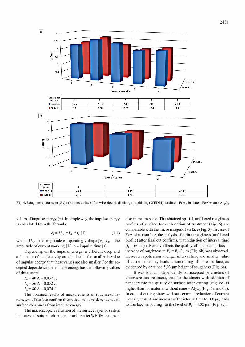
In Figure 4 the values of the roughness parameter Ra of both kind of sinters after WEDM treatment were presented. The Ra parameter – arithmetic mean deviation of the assessed profile – was adopted as a representative parameter of the surface texture (ST).
It has been found (Fig. 4a) that the value of Ra parameter only slightly depends on the type of machining (roughing or finishing).
The obtained results for FeAl sinters indicates, that reduc-tion of the time of interval between individual impulses causes an increase of Ra parameter (comparison: variant 1 with 2 and variant 4 with 3). The surface roughness also increases with an increase of current value, with maintaining the constant value of time of interval duration (comparison: variant 1 with 4 and variant 2 with 3). It was observed, that for the smallest value of current (40 A) Ra parameter is at comparable level, as in the case of cutting with a current intensity equal 56 A. The maximum height of roughness (Ra = 2,68 μm) was found for surface after finishing conducted with the highest values of current equal 80 A and the shortest time of interval between impulses (tp = 60 μs). In case of treatment of sinters without ceramic, the smallest value of parameter Ra = 1,97 μm (variant 4 – finishing) was recorded for finishing with tp = 100 μs and IA = 56 A. The value of Ra parameter decreased about 14,4% compared to surface obtained in variant 1 – finishing.
In case of materials doped with 2% vol. Al2O3 nanoceramic, reduction of value of Ra parameter with decreases of value of current was observed (Fig. 4b). The biggest difference (13,1%) between roughness after finishing and roughing was obtained for option 3 (Fig. 4b). For the surface after finishing, accord-ing to option 3 ((IA = 40 A, tp = 100 μs), the value of parameter Ra = 1,46 μm was recorded.
Effect of „smoothing” of sinter surface due the addition of nanoceramic, can be explained by the presence of homogene-ously distributed, dispersion nano-Al2O3 oxide phase. As a result of roughing electroerosion treatment melting and evaporation of the matrix material (FeAl intermetallic phase) takes place. Since ceramic does not subject to melting and erosion, it creates a thermal barrier, which fills the bottom of the crater. During the finishing, which is carried out without treated surface pen-etration, protruding peaks of craters are smoothed, and ceramic plays role of dielectric limiting the melting of matrix material. As consequence, there is no formation a new and deepening of already existing craters.
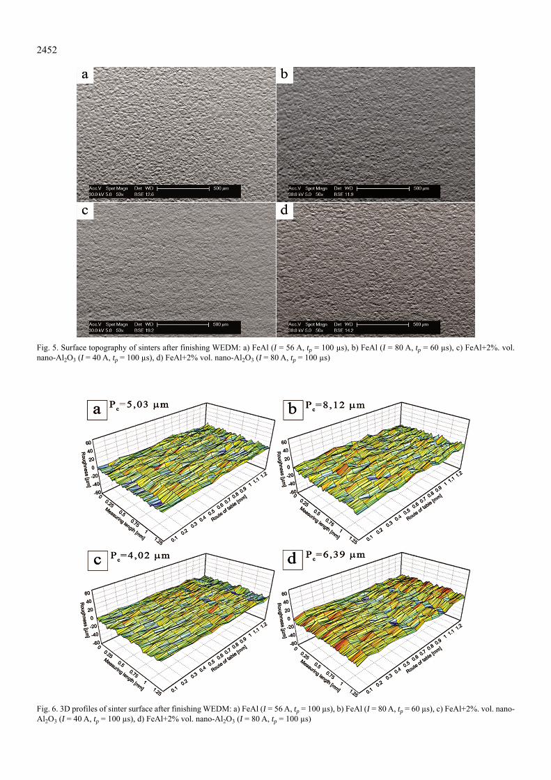
Microscopic analysis (BSE detector – “topo” view mode) of the surface of sinters with and without nanoceramic after finishing demonstrated, that the surface has an isotropic char-acter independently on applied treatment parameters (Fig. 5). The size of craters on investigated surfaces mainly depends on
2451
values of impulse energy (ei). In simple way, the impulse energy is calculated from the formula:
ei = UAr * IAr * ti [J] (1.1)
where: UAr – the amplitude of operating voltage [V], IAr – the amplitude of current working [A], ti – impulse time [s].
Depending on the impulse energy, a different deep and a diameter of single cavity are obtained – the smaller is value of impulse energy, that these values are also smaller. For the ac-cepted dependence the impulse energy has the following values of the current:
IA = 40 A – 0,037 J,IA = 56 A – 0,052 J,IA = 80 A – 0,074 J.The obtained results of measurements of roughness pa-
rameters of surface confirm theoretical positive dependence of surface roughness from impulse energy.
The macroscopic evaluation of the surface layer of sinters indicates on isotropic character of surface after WEDM treatment
also in macro scale. The obtained spatial, unfiltered roughness profiles of surface for each option of treatment (Fig. 6) are comparable with the micro images of surface (Fig. 5). In case of FeAl sinter surface, the analysis of surface roughness (unfiltered profile) after final cut confirms, that reduction of interval time (tp = 60 μs) adversely affects the quality of obtained surface – increase of roughness to Pc = 8,12 μm (Fig. 6b) was observed. However, application a longer interval time and smaller value of current intensity leads to smoothing of sinter surface, as evidenced by obtained 5,03 μm height of roughness (Fig. 6a).
It was found, independently on accepted parameters of electroerosion treatment, that for the sinters with addition of nanoceramic the quality of surface after cutting (Fig. 6c) is higher than for material without nano – Al2O3 (Fig. 6a and 6b). In case of cutting sinter without ceramic, reduction of current intensity to 40 A and increase of the interval time to 100 μs, leads to „surface smoothing“ to the level of Pc = 4,02 μm (Fig. 6c).
Fig. 4. Roughness parameter (Ra) of sinters surface after wire electric discharge machining (WEDM): a) sinters FeAl, b) sinters FeAl+nano-Al2O3
2452
Fig. 6. 3D profiles of sinter surface after finishing WEDM: a) FeAl (I = 56 A, tp = 100 μs), b) FeAl (I = 80 A, tp = 60 μs), c) FeAl+2%. vol. nano-Al2O3 (I = 40 A, tp = 100 μs), d) FeAl+2% vol. nano-Al2O3 (I = 80 A, tp = 100 μs)
Fig. 5. Surface topography of sinters after finishing WEDM: a) FeAl (I = 56 A, tp = 100 μs), b) FeAl (I = 80 A, tp = 60 μs), c) FeAl+2%. vol. nano-Al2O3 (I = 40 A, tp = 100 μs), d) FeAl+2% vol. nano-Al2O3 (I = 80 A, tp = 100 μs)
2453
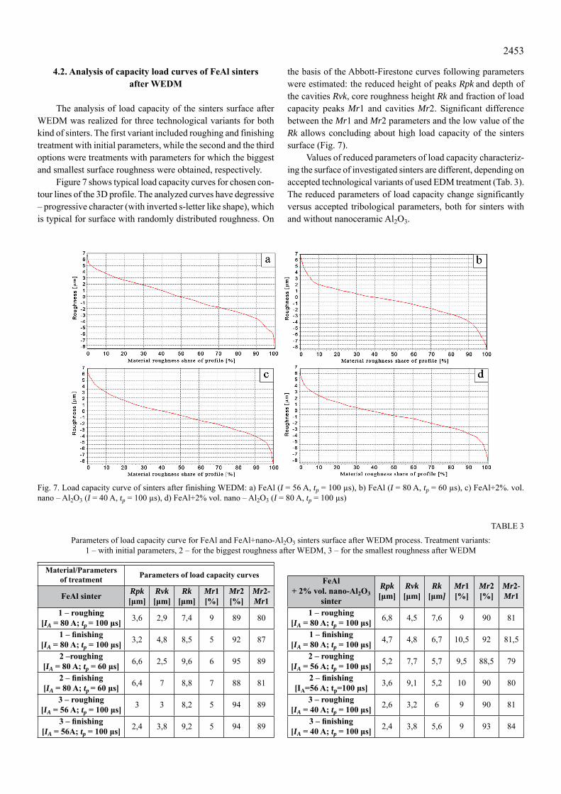
4.2. Analysis of capacity load curves of FeAl sinters after WEDM
The analysis of load capacity of the sinters surface after WEDM was realized for three technological variants for both kind of sinters. The first variant included roughing and finishing treatment with initial parameters, while the second and the third options were treatments with parameters for which the biggest and smallest surface roughness were obtained, respectively.
Figure 7 shows typical load capacity curves for chosen con-tour lines of the 3D profile. The analyzed curves have degressive – progressive character (with inverted s-letter like shape), which is typical for surface with randomly distributed roughness. On
the basis of the Abbott-Firestone curves following parameters were estimated: the reduced height of peaks Rpk and depth of the cavities Rvk, core roughness height Rk and fraction of load capacity peaks Mr1 and cavities Mr2. Significant difference between the Mr1 and Mr2 parameters and the low value of the Rk allows concluding about high load capacity of the sinters surface (Fig. 7).
Values of reduced parameters of load capacity characteriz-ing the surface of investigated sinters are different, depending on accepted technological variants of used EDM treatment (Tab. 3). The reduced parameters of load capacity change significantly versus accepted tribological parameters, both for sinters with and without nanoceramic Al2O3.
Fig. 7. Load capacity curve of sinters after finishing WEDM: a) FeAl (I = 56 A, tp = 100 μs), b) FeAl (I = 80 A, tp = 60 μs), c) FeAl+2%. vol. nano – Al2O3 (I = 40 A, tp = 100 μs), d) FeAl+2% vol. nano – Al2O3 (I = 80 A, tp = 100 μs)
TABLE 3
Parameters of load capacity curve for FeAl and FeAl+nano-Al2O3 sinters surface after WEDM process. Treatment variants: 1 – with initial parameters, 2 – for the biggest roughness after WEDM, 3 – for the smallest roughness after WEDM
FeAl+ 2% vol. nano-Al2O3
sinter
Rpk [μm]
Rvk [μm]
Rk [μm]
Mr1 [%]
Mr2 [%]
Mr2-Mr1
1 – roughing[IA = 80 A; tp = 100 μs] 6,8 4,5 7,6 9 90 81
1 – fi nishing[IA = 80 A; tp = 100 μs] 4,7 4,8 6,7 10,5 92 81,5
2 – roughing[IA = 56 A; tp = 100 μs] 5,2 7,7 5,7 9,5 88,5 79
2 – fi nishing[IA=56 A; tp=100 μs] 3,6 9,1 5,2 10 90 80
3 – roughing[IA = 40 A; tp = 100 μs] 2,6 3,2 6 9 90 81
3 – fi nishing[IA = 40 A; tp = 100 μs] 2,4 3,8 5,6 9 93 84
Material/Parameters of treatment Parameters of load capacity curves
FeAl sinter Rpk [μm]
Rvk [μm]
Rk [μm]
Mr1 [%]
Mr2 [%]
Mr2-Mr1
1 – roughing [IA = 80 A; tp = 100 μs] 3,6 2,9 7,4 9 89 80
1 – fi nishing[IA = 80 A; tp = 100 μs] 3,2 4,8 8,5 5 92 87
2 –roughing[IA = 80 A; tp = 60 μs] 6,6 2,5 9,6 6 95 89
2 – fi nishing[IA = 80 A; tp = 60 μs] 6,4 7 8,8 7 88 81
3 – roughing[IA = 56 A; tp = 100 μs] 3 3 8,2 5 94 89
3 – fi nishing[IA = 56A; tp = 100 μs] 2,4 3,8 9,2 5 94 89
2454
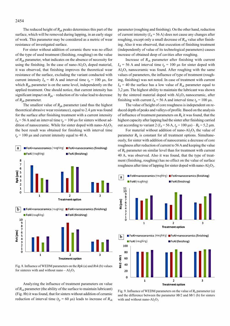
The reduced height of Rpk peaks determines this part of the surface, which will be removed during lapping, in an early stage of work. This parameter may be considered as a metric of wear resistance of investigated surface.
For sinter without addition of ceramic there was no effect of the type of used treatment (finishing, roughing) on the value of Rpk parameter, what indicates on the absence of necessity for using the finishing. In the case of nano-Al2O3 doped material, it was observed, that finishing improves the theoretical wear resistance of the surface, excluding the variant conducted with current intensity IA = 40 A and interval time tp = 100 μs, for which Rpk parameter is on the same level, independently on the applied treatment. One should notice, that current intensity has significant impact on Rpk – reduction of its value lead to decrease of Rpk parameter.
The smallest value of Rpk parameter (and thus the highest theoretical abrasive wear resistance), equal to 2.4 μm was found for the surface after finishing treatment with a current intensity IA = 56 A and an interval time tp = 100 μs for sinters without ad-dition of nanoceramic. While for sinter doped with nano-Al2O3 the best result was obtained for finishing with interval time tp = 100 μs and current intensity equal to 40 A.
Fig. 8. Influence of WEDM parameters on the Rpk (a) and Rvk (b) values for sinteres with and without nano – Al2O3
Analyzing the influence of treatment parameters on value of Rvk parameter (the ability of the surface to maintain lubricant) (Fig. 8b) it was found, that for sinters without addition of ceramic reduction of interval time (tp = 60 μs) leads to increase of Rvk
parameter (roughing and finishing). On the other hand, reduction of current intensity (IA = 56 A) does not cause any changes after roughing, except only a small decrease of Rvk value after finish-ing. Also it was observed, that execution of finishing treatment (independently of value of its technological parameters) causes increase of obtained deep of cavities after roughing.
Increase of Rvk parameter after finishing with current IA = 56 A and interval time tp = 100 μs for sinter doped with Al2O3 nanoceramic was found. After roughing with the same values of parameters, the influence of type of treatment (rough-ing, finishing) was not noted. In case of treatment with current IA = 40 the surface has a low value of Rvk parameter equal to 3,2 μm. The highest ability to maintain the lubricant was shown by the sintered material doped with Al2O3 nanoceramic, after finishing with current IA = 56 A and interval time tp = 100 μs.
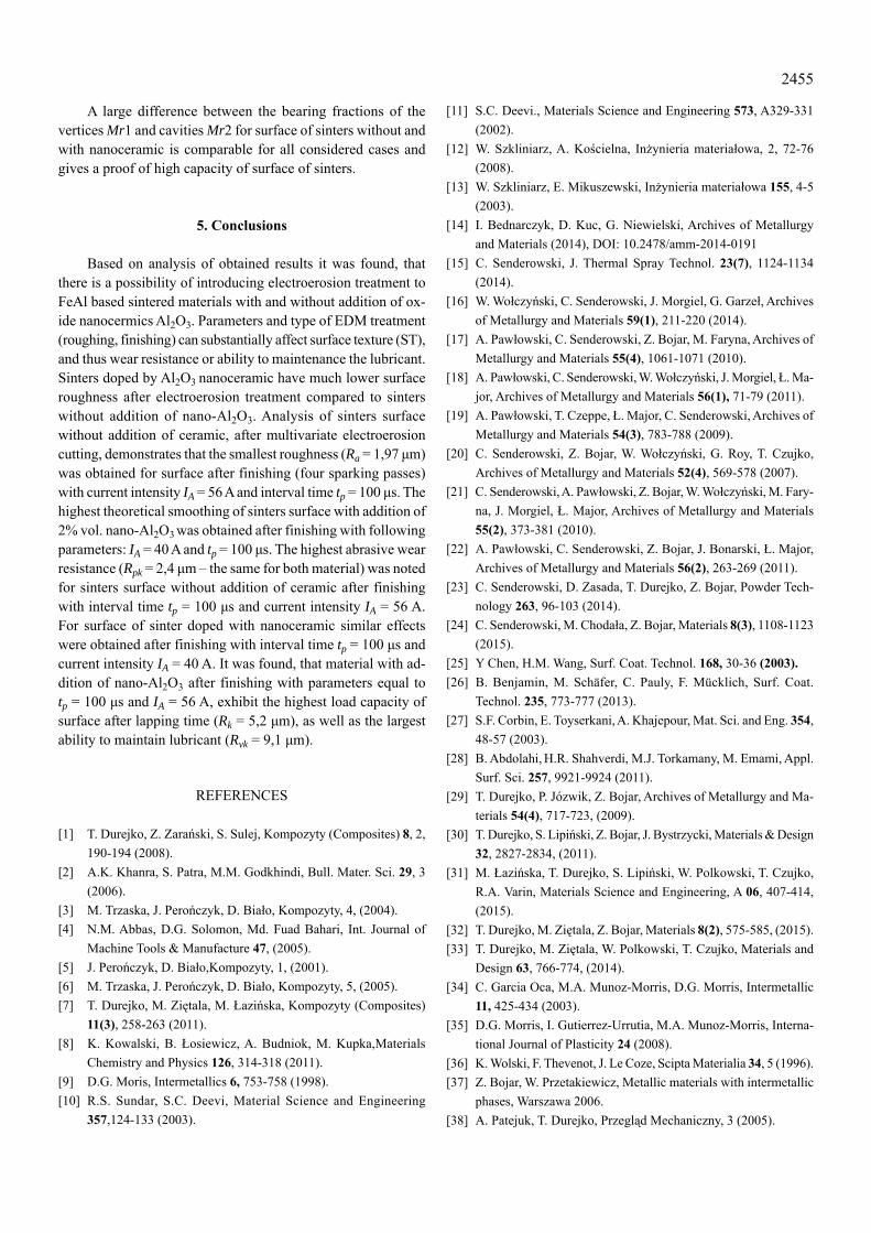
The value of height of core roughness is independent on re-duced depth of peaks and valleys of profile. Based on the analysis of influence of treatment parameters on Rk it was found, that the highest capacity after lapping had the sinter after finishing carried out according to variant 2 (IA = 56 A, tp = 100 μs) – Rk = 5,2 μm.
For material without addition of nano-Al2O3 the value of parameter Rk is constant for all treatment options. Simultane-ously, for sinter with addition of nanoceramic a decrease of core roughness after reduction of current to 56 A and keeping the value of Rk parameter on similar level than for treatment with current 40 A, was observed. Also it was found, that the type of treat-ment (finishing, roughing) has no effect on the value of surface roughness after time of lapping for sinter doped with nano-Al2O3.
Fig. 9. Influence of WEDM parameters on the value of Rk parameter (a) and the difference between the parameter Mr2 and Mr1 (b) for sinters with and without nano-Al2O3
2455
A large difference between the bearing fractions of the vertices Mr1 and cavities Mr2 for surface of sinters without and with nanoceramic is comparable for all considered cases and gives a proof of high capacity of surface of sinters.
5. Conclusions
Based on analysis of obtained results it was found, that there is a possibility of introducing electroerosion treatment to FeAl based sintered materials with and without addition of ox-ide nanocermics Al2O3. Parameters and type of EDM treatment (roughing, finishing) can substantially affect surface texture (ST), and thus wear resistance or ability to maintenance the lubricant. Sinters doped by Al2O3 nanoceramic have much lower surface roughness after electroerosion treatment compared to sinters without addition of nano-Al2O3. Analysis of sinters surface without addition of ceramic, after multivariate electroerosion cutting, demonstrates that the smallest roughness (Ra = 1,97 μm) was obtained for surface after finishing (four sparking passes) with current intensity IA = 56 A and interval time tp = 100 μs. The highest theoretical smoothing of sinters surface with addition of 2% vol. nano-Al2O3 was obtained after finishing with following parameters: IA = 40 A and tp = 100 μs. The highest abrasive wear resistance (Rpk = 2,4 μm – the same for both material) was noted for sinters surface without addition of ceramic after finishing with interval time tp = 100 μs and current intensity IA = 56 A. For surface of sinter doped with nanoceramic similar effects were obtained after finishing with interval time tp = 100 μs and current intensity IA = 40 A. It was found, that material with ad-dition of nano-Al2O3 after finishing with parameters equal to tp = 100 μs and IA = 56 A, exhibit the highest load capacity of surface after lapping time (Rk = 5,2 μm), as well as the largest ability to maintain lubricant (Rvk = 9,1 μm).
REFERENCES
[1] T. Durejko, Z. Zarański, S. Sulej, Kompozyty (Composites) 8, 2, 190-194 (2008).
[2] A.K. Khanra, S. Patra, M.M. Godkhindi, Bull. Mater. Sci. 29, 3 (2006).
[3] M. Trzaska, J. Perończyk, D. Biało, Kompozyty, 4, (2004).[4] N.M. Abbas, D.G. Solomon, Md. Fuad Bahari, Int. Journal of
Machine Tools & Manufacture 47, (2005).[5] J. Perończyk, D. Biało,Kompozyty, 1, (2001).[6] M. Trzaska, J. Perończyk, D. Biało, Kompozyty, 5, (2005).[7] T. Durejko, M. Ziętala, M. Łazińska, Kompozyty (Composites)
11(3), 258-263 (2011).[8] K. Kowalski, B. Łosiewicz, A. Budniok, M. Kupka,Materials
Chemistry and Physics 126, 314-318 (2011).[9] D.G. Moris, Intermetallics 6, 753-758 (1998).[10] R.S. Sundar, S.C. Deevi, Material Science and Engineering
357,124-133 (2003).
[11] S.C. Deevi., Materials Science and Engineering 573, A329-331 (2002).
[12] W. Szkliniarz, A. Kościelna, Inżynieria materiałowa, 2, 72-76 (2008).
[13] W. Szkliniarz, E. Mikuszewski, Inżynieria materiałowa 155, 4-5 (2003).
[14] I. Bednarczyk, D. Kuc, G. Niewielski, Archives of Metallurgy and Materials (2014), DOI: 10.2478/amm-2014-0191
[15] C. Senderowski, J. Thermal Spray Technol. 23(7), 1124-1134 (2014).
[16] W. Wołczyński, C. Senderowski, J. Morgiel, G. Garzeł, Archives of Metallurgy and Materials 59(1), 211-220 (2014).
[17] A. Pawłowski, C. Senderowski, Z. Bojar, M. Faryna, Archives of Metallurgy and Materials 55(4), 1061-1071 (2010).
[18] A. Pawłowski, C. Senderowski, W. Wołczyński, J. Morgiel, Ł. Ma-jor, Archives of Metallurgy and Materials 56(1), 71-79 (2011).
[19] A. Pawłowski, T. Czeppe, Ł. Major, C. Senderowski, Archives of Metallurgy and Materials 54(3), 783-788 (2009).
[20] C. Senderowski, Z. Bojar, W. Wołczyński, G. Roy, T. Czujko, Archives of Metallurgy and Materials 52(4), 569-578 (2007).
[21] C. Senderowski, A. Pawłowski, Z. Bojar, W. Wołczyński, M. Fary-na, J. Morgiel, Ł. Major, Archives of Metallurgy and Materials 55(2), 373-381 (2010).
[22] A. Pawłowski, C. Senderowski, Z. Bojar, J. Bonarski, Ł. Major, Archives of Metallurgy and Materials 56(2), 263-269 (2011).
[23] C. Senderowski, D. Zasada, T. Durejko, Z. Bojar, Powder Tech-nology 263, 96-103 (2014).
[24] C. Senderowski, M. Chodała, Z. Bojar, Materials 8(3), 1108-1123 (2015).
[25] Y Chen, H.M. Wang, Surf. Coat. Technol. 168, 30-36 (2003).[26] B. Benjamin, M. Schäfer, C. Pauly, F. Mücklich, Surf. Coat.
Technol. 235, 773-777 (2013).[27] S.F. Corbin, E. Toyserkani, A. Khajepour, Mat. Sci. and Eng. 354,
48-57 (2003).[28] B. Abdolahi, H.R. Shahverdi, M.J. Torkamany, M. Emami, Appl.
Surf. Sci. 257, 9921-9924 (2011).[29] T. Durejko, P. Józwik, Z. Bojar, Archives of Metallurgy and Ma-
terials 54(4), 717-723, (2009).[30] T. Durejko, S. Lipiński, Z. Bojar, J. Bystrzycki, Materials & Design
32, 2827-2834, (2011).[31] M. Łazińska, T. Durejko, S. Lipiński, W. Polkowski, T. Czujko,
R.A. Varin, Materials Science and Engineering, A 06, 407-414, (2015).
[32] T. Durejko, M. Ziętala, Z. Bojar, Materials 8(2), 575-585, (2015).[33] T. Durejko, M. Ziętala, W. Polkowski, T. Czujko, Materials and
Design 63, 766-774, (2014).[34] C. Garcia Oca, M.A. Munoz-Morris, D.G. Morris, Intermetallic
11, 425-434 (2003).[35] D.G. Morris, I. Gutierrez-Urrutia, M.A. Munoz-Morris, Interna-
tional Journal of Plasticity 24 (2008).[36] K. Wolski, F. Thevenot, J. Le Coze, Scipta Materialia 34, 5 (1996).[37] Z. Bojar, W. Przetakiewicz, Metallic materials with intermetallic
phases, Warszawa 2006.[38] A. Patejuk, T. Durejko, Przegląd Mechaniczny, 3 (2005).
2456
[39] F. Weng, M. Her, Int. J. Adv. Manuf. Technol. 19, 266-270 (2002).[40] S. Yeo, G. Yap, Int. J. Adv. Manuf. Technol. 18, (2001).[41] J. Qu, A. Shih, R. Scattergood, ASME 124, 702-707 (2002).[42] A. Muttamara, Y. Fukuzawa, N. Mohri, T. Tani, J. Mater. Process.
Technol. 140, 243-247 (2003).[43] N. Mohri, Y. Fukuzawa, T. Tani, Ann. CIRP 51, 112-116 (2002).[44] T. Durejko, A. Strąk, S. Lipiński, Kompozyty (Composites) 11
(3), 225-229 (2011).
[45] J. Tomasik, D. Biało, Mechanik 1, 26-28 (2003).[46] K.E. Oczoś, V. Liubimov, Surface geometry, Rzeszów 2003.[47] S. Adamczak, Surface geometry metrology. Outlines of shape,
waviness and roughness, Warszawa 2008.[48] M. Bigerelle, A. Iost, Tribology International 40, 1319-1334
(2007).
Received:20 April 2015.