
Wszelkie prawa zastrzeone. adna cz niniejszej publikacji...
152
Wszelkie prawa zastrzeone. adna cz niniejszej publikacji nie moe by reprodukowana i przekazywana w jakiejkolwiek formie zapisu. Na prawach rkopisu. Wydrukowano z materialów dostarczonych przez Autora w Drukarni Cyfrowej Kserkop sp. z o.o. w Krakowie. Wydawnictwo Wydzialu Elektrotechniki, Automatyki, Informatyki i Elektroniki Akademia Górniczo-Hutnicza Kraków 2007 ISBN 978-83-88309-71-7
Transcript of Wszelkie prawa zastrzeone. adna cz niniejszej publikacji...

Wszelkie prawa zastrze�one.
�adna cz��� niniejszej publikacji nie mo�e by� reprodukowana i przekazywana w jakiejkolwiek formie zapisu.
Na prawach r�kopisu.
Wydrukowano z materiałów dostarczonych przez Autora w Drukarni Cyfrowej Kserkop sp. z o.o. w Krakowie.
Wydawnictwo Wydziału Elektrotechniki, Automatyki, Informatyki i Elektroniki
Akademia Górniczo-Hutnicza
Kraków 2007 ISBN 978-83-88309-71-7
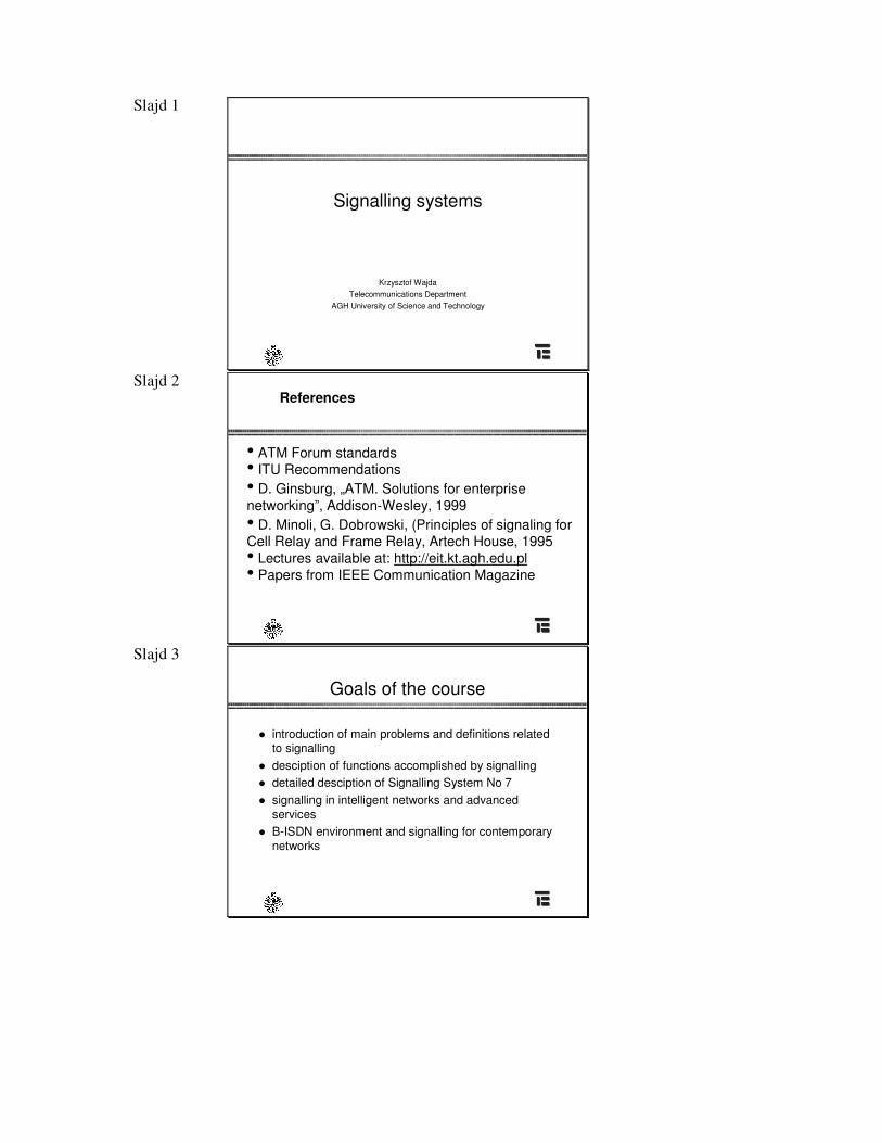
Slajd 1
Signalling systems
Krzysztof WajdaTelecommunications Department
AGH University of Science and Technology
Slajd 2 References
• ATM Forum standards• ITU Recommendations• D. Ginsburg, „ATM. Solutions for enterprise networking”, Addison-Wesley, 1999• D. Minoli, G. Dobrowski, (Principles of signaling for Cell Relay and Frame Relay, Artech House, 1995• Lectures available at: http://eit.kt.agh.edu.pl• Papers from IEEE Communication Magazine
Slajd 3
Goals of the course
� introduction of main problems and definitions relatedto signalling
� desciption of functions accomplished by signalling� detailed desciption of Signalling System No 7� signalling in intelligent networks and advanced
services� B-ISDN environment and signalling for contemporary
networks
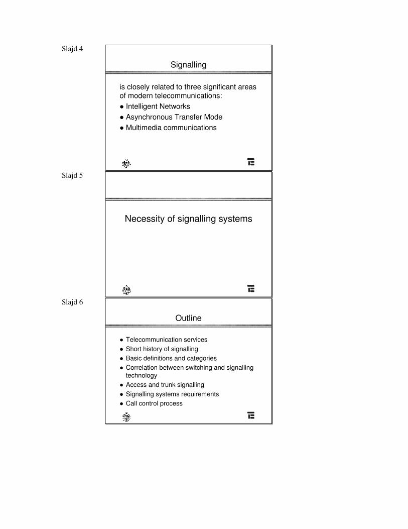
Slajd 4
Signalling
is closely related to three significant areas of modern telecommunications:� Intelligent Networks� Asynchronous Transfer Mode� Multimedia communications
Slajd 5
Necessity of signalling systems
Slajd 6
Outline
� Telecommunication services� Short history of signalling� Basic definitions and categories� Correlation between switching and signalling
technology� Access and trunk signalling� Signalling systems requirements� Call control process
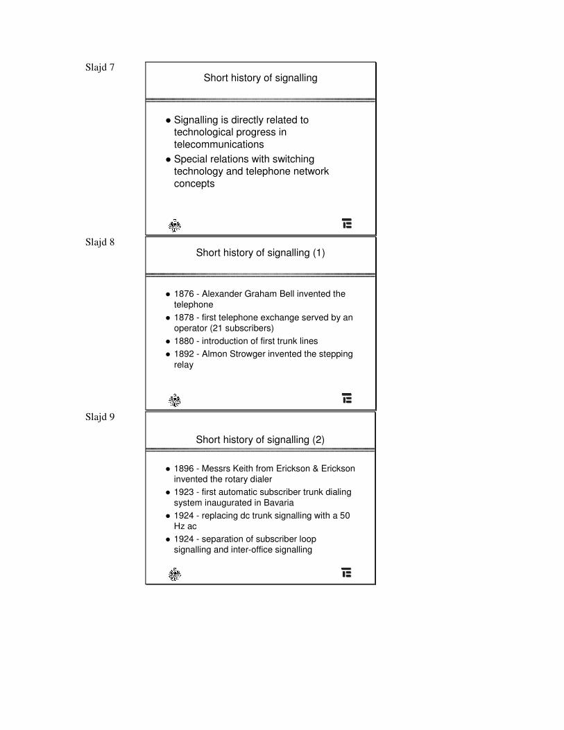
Slajd 7 Short history of signalling
� Signalling is directly related totechnological progress in telecommunications
� Special relations with switching technology and telephone network concepts
Slajd 8 Short history of signalling (1)
� 1876 - Alexander Graham Bell invented the telephone
� 1878 - first telephone exchange served by anoperator (21 subscribers)
� 1880 - introduction of first trunk lines� 1892 - Almon Strowger invented the stepping
relay
Slajd 9
Short history of signalling (2)
� 1896 - Messrs Keith from Erickson & Erickson invented the rotary dialer
� 1923 - first automatic subscriber trunk dialingsystem inaugurated in Bavaria
� 1924 - replacing dc trunk signalling with a 50Hz ac
� 1924 - separation of subscriber loop signalling and inter-office signalling
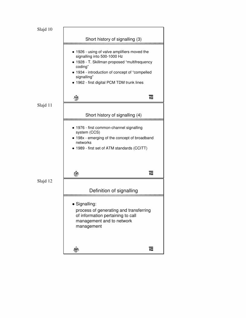
Slajd 10
Short history of signalling (3)
� 1926 - using of valve amplifiers moved the signalling into 500-1000 Hz
� 1928 - T. Skillman proposed “multifrequency coding”
� 1934 - introduction of concept of “compelled signalling”
� 1962 - first digital PCM TDM trunk lines
Slajd 11
Short history of signalling (4)
� 1976 - first common-channel signallingsystem (CCS)
� 198x - emerging of the concept of broadband networks
� 1989 - first set of ATM standards (CCITT)
Slajd 12
Definition of signalling
� Signalling:process of generating and transferring of information pertaining to call management and to network management

Slajd 13 Basic definitions and categories
� call� connection� phases of call� classification of signalling concepts and
systems
Slajd 14
Call vs connection
� Call means formal association between two parties involving activation of information transfer protocol;has also meaning as object which can be created and destroyed. Many calls taken together create traffic stream.
� Connection has mainly technical meaning; it is creation of technical means for information transportation
� In telephone environment call = connection� In B-ISDN environment we can have one call
composed of many connections
Slajd 15
Classification (topological criterion)
� Inter-Customer Premises Equipment Signalling
� Intra-CPE Signalling� Customer Line Signalling� Interoffice Signalling� Special Services Signalling� Advanced Services Signalling
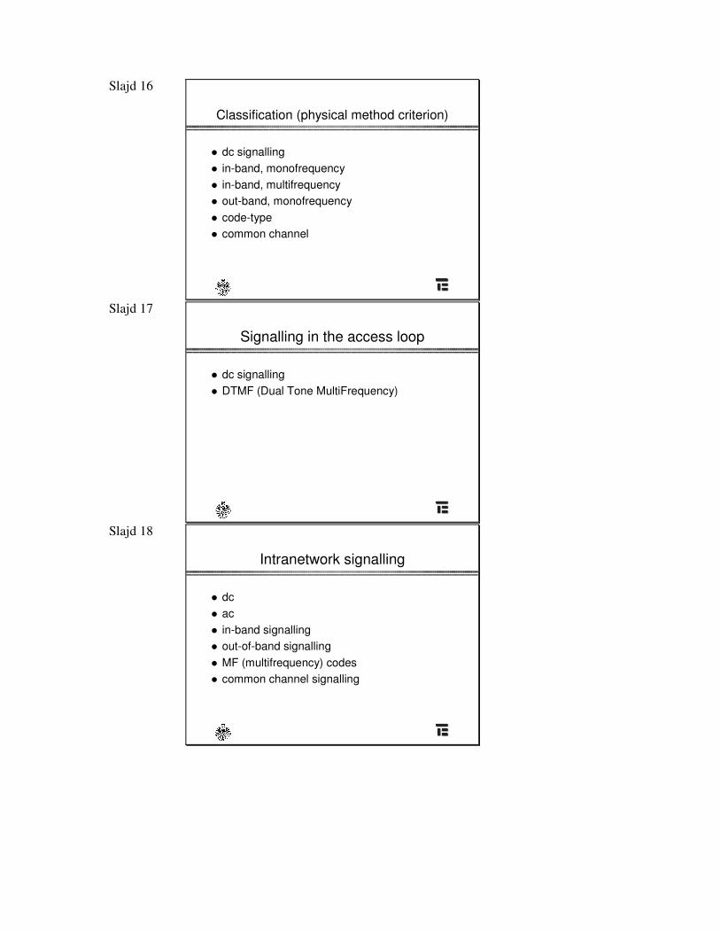
Slajd 16
Classification (physical method criterion)
� dc signalling� in-band, monofrequency� in-band, multifrequency� out-band, monofrequency� code-type� common channel
Slajd 17
Signalling in the access loop
� dc signalling� DTMF (Dual Tone MultiFrequency)
Slajd 18
Intranetwork signalling
� dc� ac� in-band signalling� out-of-band signalling� MF (multifrequency) codes � common channel signalling
Slajd 19
Classification (functional criterion)
� Supervisory: monitoring the status of a line or circuit(idle, busy)
� Adressing: transferring routing and destination signals
� Alerting: anouncing the incoming call� Billing: generation and collection of biling information
Slajd 20 Correlation between switching and
signalling technology
� There is tight relation between main technologies used in switching and transmision equipment and signalling concepts
� It was easier to change the signalling concept than intra-network technology
� There is strong pressure to preserve usage of old technology in new changing environment- issues of interworking
Slajd 21 Correlation between switching and
signalling technology
switching technology signalling
step-by-step dc,
cross-bar ac, MF, out-band
electronic MF, out-band
SPC message based
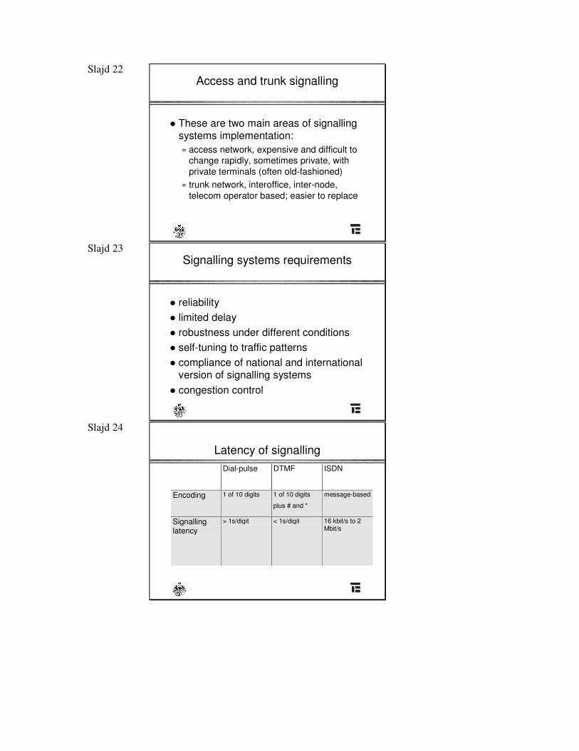
Slajd 22 Access and trunk signalling
� These are two main areas of signalling systems implementation:» access network, expensive and difficult to
change rapidly, sometimes private, with private terminals (often old-fashioned)
» trunk network, interoffice, inter-node,telecom operator based; easier to replace
Slajd 23 Signalling systems requirements
� reliability� limited delay� robustness under different conditions� self-tuning to traffic patterns� compliance of national and international
version of signalling systems � congestion control
Slajd 24
Latency of signallingDial-pulse DTMF ISDN
Encoding 1 of 10 digits 1 of 10 digits
plus # and *
message-based
Signallinglatency
> 1s/digit < 1s/digit 16 kbit/s to 2Mbit/s
Slajd 25
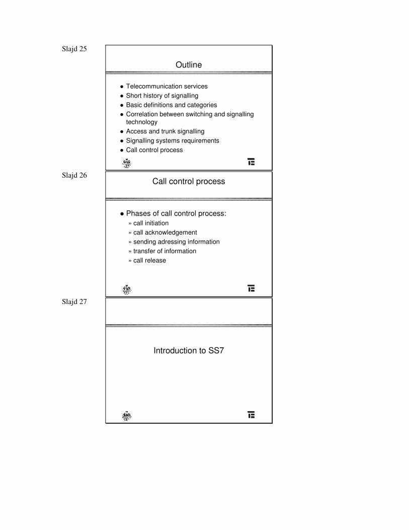
Outline
� Telecommunication services� Short history of signalling� Basic definitions and categories� Correlation between switching and signalling
technology� Access and trunk signalling� Signalling systems requirements� Call control process
Slajd 26 Call control process
� Phases of call control process:» call initiation» call acknowledgement» sending adressing information» transfer of information» call release
Slajd 27
Introduction to SS7
Slajd 28
Common Channel Signalling
� This concept was possible with significant advances in network software engineering
� SS6 as first attempt to CCS� This is out-of-band signalling method in which
common data channel conveys signalling messages related to a number of trunks
Slajd 29
CCS6 - CCIS
� CCIS - Common Channel Interoffice Signalling
� CCS6 - Signalling System No. 6 introduced in1976 by AT&T
� Features of CCS6:» not a layered system» only for trunk signalling» routing based on the basis of permanent virtual
signalling circuits
Slajd 30
CCS6 - drawbacks
� large efforts to manage banded routing� limited lengths� low speed links� non-modular structure
Slajd 31
SS7
� Work on SS7 began in mid 1970s� CCITT (ITU-T currently) as leading
force� “800 service” and “calling card service”
as first attempts to new concept� used layered approach to system
construction
Slajd 32
SS7 supports signalling for:
� Public Switched Telephone Networks� ISDN� Public mobile networks� Operations, administrations and maintenance � as a basis for interactions with network data
bases and service control points for advanced services
Slajd 33
SS7 network structure
- centrala telefoniczna
- SP – signalling point
STP – Signalling Transfer Point
Sie� telefoniczna
Sie� sygnalizacyjna SS7
Slajd 34
Signalling network elements
� SP - Signalling Point� STP - Signal Transfer Point� signalling links� SCP - Service Control Points� OAM - Operation, Administration and
Maintenance centres
Slajd 35
Signalling network structure
� Reflects the structure of telecommunication network to be served by signalling and administration aspects
� Signalling system can be planned:» purely on a per signalling relation basis - associated
signalling for large traffic volumes and some quasi-associated signalling for low volume signalling relations
» as an independent network with regard to common channel signalling needs - this leads to mainly quasi-associated signalling with scarce associated signalling for high volume traffic patterns
Slajd 36
Worldwide signalling network
� Structured into two functionallyindependent levels:» international» national
� such structure helps to split responsibility and separates numbering plans
Slajd 37
Signalling point modes
� Originating point of the message is a signallingpoint at which message is generated, i.e. there is location of the source User Part function
� Destination point of the message is a signallingpoint to which message is destined, i.e. there is location of the receiving User Part function
� Signalling point at which a message is received on one signalling link and transferred to another link is aSignal Transfer Point (STP)
Slajd 38
Signalling relation
� Signalling relation exists between two nodes when they are capable of exchanging signalling messages through signalling network
Slajd 39
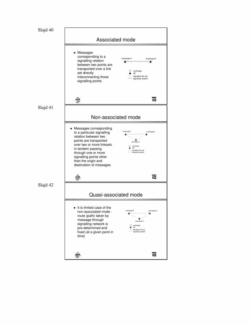
Signalling modes
� “Mode” refers to the type of association between path taken by the signalling message and its corresponding signalling relation:» Associated» Non-associated» Quasi-associated
Slajd 40
Associated mode
� Messages corresponding to asignalling relation between two points are transported over a linkset directly inteconnecting those signalling points
exchange A exchange B
exchangeSP
signalling relationsignalling link set
Slajd 41
Non-associated mode
� Messages correspondingto a particular signalling relation between two points are transported over two or more linksets in tandem passing through one or more signalling points other than the origin and destination of messages
exchange A
exchangeSP
signalling relationsignalling link set
exchange C
exchange B
Slajd 42
Quasi-associated mode
� It is limited case of the non-associated mode -route (path) taken bymessage through signalling network is pre-determined and fixed (at a given point in time)
exchange
exchange B
exchange C
SP
signalling relationsignalling link set
exchange A
Slajd 43
SS7 - main building blocks
� Message Transfer Part (MTP): block which ensures reliable transmission of functional signalling messages with high availability
� User Parts (UP): block which provides functions to manage number of services
Slajd 44
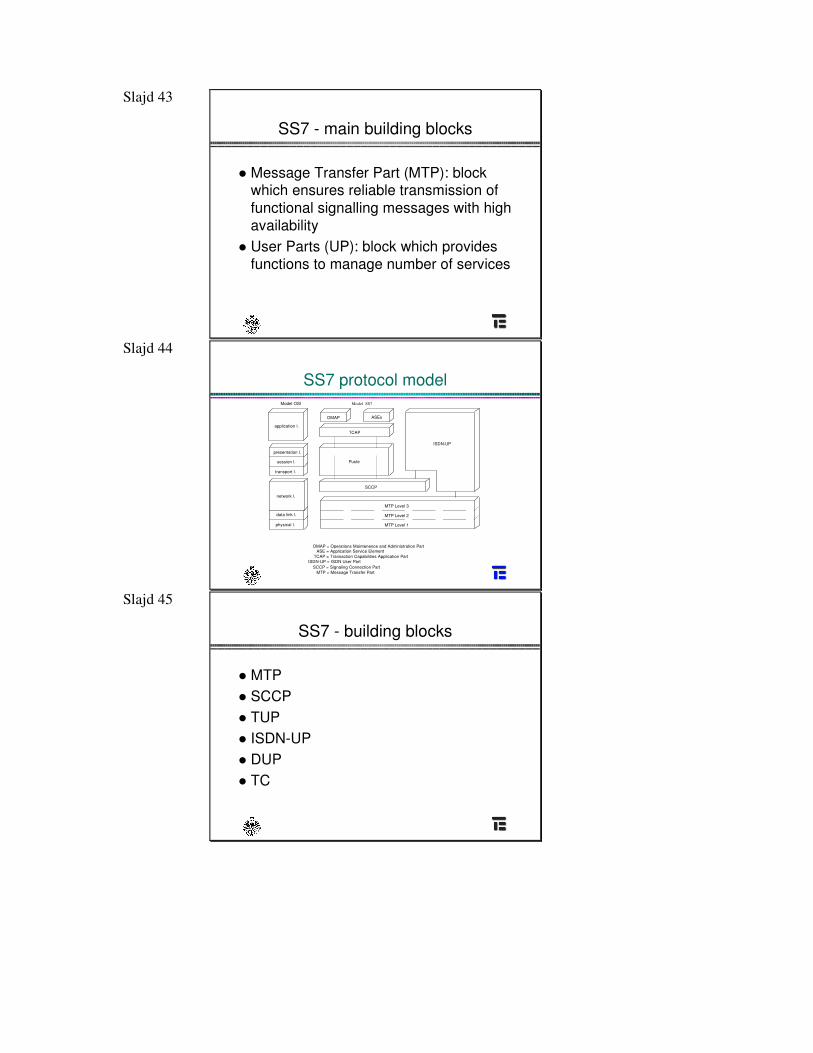
SS7 protocol model
Puste
Model OSI Model SS7
OMAP ASEs
TCAP
SCCP
ISDN-UP
MTP Level 3
MTP Level 2
MTP Level 1
OMAP = Operations Maintenence and Administration PartASE = Application Service Element
TCAP = Transaction Capabilities Application PartISDN-UP = ISDN User Part
SCCP = Signaling Connection PartMTP = Message Transfer Part
application l.
presentation l.
session l.
transport l.
network l.
data link l.
physical l.
Slajd 45
SS7 - building blocks
� MTP� SCCP� TUP� ISDN-UP� DUP� TC
Slajd 46 Institutions engaged in
standardization process of SS7
� ITU-T (former CCITT)� Bellcore� ANSI� all national standard institutes
Slajd 47
ITU-T recommendations
Key recommendationsGeneral description Q.700 Q.771-Q.775MTP Q.701-Q.704, Q.706, Q.707TUP Q.721-Q.725Supplementary services Q.730DUP Q.741 Q.701-Q.704, Q.706, Q.707ISDN-UP Q.761-Q.764, Q.766 Q.721-Q.725SCCP Q.711-Q.714, Q.716 Q.730Transaction Capabilities Q.771-Q.775 Q.771-Q.775Operations, maintenance andadministration part (OMAP)
Q.795 Q.771-Q.775
Slajd 48
ITU-T recommendations
Additional recommendationsSignalling network structure Q.705 Q.771-Q.775Numbering of internationalsignalling point codes
Q.708
Hypothetical signalling referenceconnection
Q.709
PBX application Q.710Test specifications Q.780-Q783 Q.701-Q.704, Q.706, Q.707Monitoring and measurements Q.791 Q.721-Q.725
Slajd 49
Basic architectural and functional components of SS7
Slajd 50
Signalling link
� MTP - structure and functions� Physical layer requirements and
standards� Signalling unit formats� Link protocol operation� Error detection and recovery� Flow control issues
Slajd 51
MTP
� Provides a reliable transfer and delivery of signalling messages across the signalling network
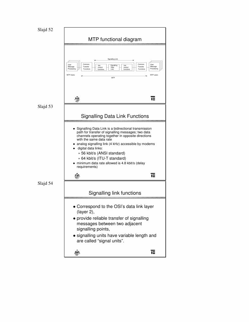
� Consists of levels 1-3 of SS7 protocol:» Signalling Data Link Functions (Level 1)» Signalling Link functions (Level 2)» Signalling Network Functions (Level 3)
� Uses datagram mode
Signalling link – prz�sło sygnalizacyjne
Slajd 52
MTP functional diagram
MTP
MTP Users MTP users
Signalling Link
link controlfunctions
link controlfunctions
UserMessageProcessing
UserMessageProcessing
SignallingDataLink
CommonTransferFunctions
CommonTransferFunctions
Slajd 53
Signalling Data Link Functions
� Signalling Data Link is a bidirectional transmission path for transfer of signalling messages; two datachannels operating together in opposite directions with the same data rate
� analog signalling link (4 kHz) accessible by modems� digital data links:
» 56 kbit/s (ANSI standard)» 64 kbit/s (ITU-T standard)
� minimum data rate allowed is 4.8 kbit/s (delay requirements)
Slajd 54
Signalling link functions
� Correspond to the OSI’s data link layer(layer 2),
� provide reliable transfer of signalling messages between two adjacent signalling points,
� signalling units have variable length and are called “signal units”.
Slajd 55
Signal unit formats
Slajd 56
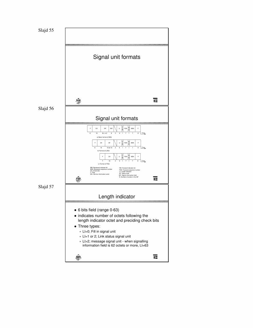
Signal unit formats
F CK LI FSN BSN F
F CK SF LI FSN BSN F
F CK LI FSN BSN F
FIB
FIB
FIB
B
BI
B
BI
B
BI
a) Basic format of MSU
b) Format of LSSU
c) Format of FISU
8 16 8n, n>2 8 2 6 1 7 1 7 8
8 16 8 lub 16 2 6 1 7 1 7 8
7 16 2 6 1 7 1 7 8
BIB: Backward indicator bit BSN: Backward sequence number
CK: Check bits F: Flag
FIB: Forward indicator bit FSN: Forward sequence number
LI: Length indicator
N: Number of octets in the SIF
SF: Status field SIO: Service information octet SIF: Signal information field
SIF SIO
Time
Time
Time
Slajd 57
Length indicator
� 6 bits field (range 0-63)� indicates number of octets following the
length indicator octet and preciding check bits� Three types:
» LI=0; Fill in signal unit» LI=1 or 2; Link status signal unit» LI>2; message signal unit - when signalling
information field is 62 octets or more, LI=63
Slajd 58
Service Information Octet
� divided into service indicator and the subservice field,
� service indicator associates signalling information with particular user part(only in MSU).
Slajd 59
Sequence numbering + indicator bits
� Forward sequence number is the sequence number of the signal unit this field belongs
� Backward sequence number is the sequence number of a signal unit being acknowledged
� Both fields range from 0 to 127� Indicator bits (forward and backward)
together with sequence numbers are used in basic error control
Slajd 60
Signalling information field (SIF)
� consists of an integral number of octets� in the range from 2 to 272, but:
– up to 62 bytes in international networks,– up to 272 bytes in national networks,
� format and codes of SIF are defined in description of user parts.
Slajd 61
Status field
� Used in LSSU,� Identified by a length indicator value
equal to 1 or 2 (when LI=1, the statusfield consists of 1 octet, etc.)
Slajd 62
Check bits
� Error detection is done by means of 16 check bits provided at each signal unit» the reminder after multiplication by
and then division (modulo 2) by the generatorpolynomialof the content of the signal unit existing between, but not including, the final bit of the opening flagand the first bit of the check, excluding bits inserted for transparency.
x x x16 12 5 1+ + +
x16
Slajd 63
„Zero” insertion and deletion
� The flag code should not to be imitated by any other part of the signal unit. To ensure it, the transmitting signalling link terminal inserts a “0” after every sequence of five consecutive 1s before the flags are attached and the signal unit is transmitted,
� At the receiving end, after flag detection and removal,each „0” which directly follows a sequence of five consecutive 1s is deleted,
� „bit stuffing”.
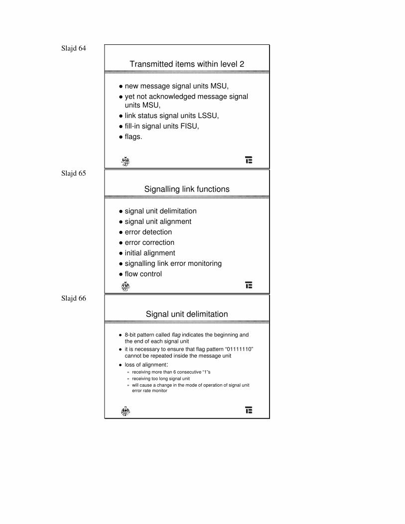
Slajd 64
Transmitted items within level 2
� new message signal units MSU,� yet not acknowledged message signal
units MSU, � link status signal units LSSU,� fill-in signal units FISU,� flags.
Slajd 65
Signalling link functions
� signal unit delimitation� signal unit alignment� error detection� error correction� initial alignment� signalling link error monitoring� flow control
Slajd 66
Signal unit delimitation
� 8-bit pattern called flag indicates the beginning and the end of each signal unit
� it is necessary to ensure that flag pattern “01111110”cannot be repeated inside the message unit
� loss of alignment:» receiving more than 6 consecutive “1”s» receiving too long signal unit» will cause a change in the mode of operation of signal unit
error rate monitor
Slajd 67
Error detection
� Performed by means of 16 check bits� They are located at the end of signal unit� Received check bits are compared with check
bits generated by receiving terminal byoperating on the preceding bitsof signal unit
� If error is detected (inconsistency), signal unit is discarded
Slajd 68
Error correction
� Two ways of error correction:» Basic method applies for signalling links
with one-way propagation delay less than15 ms
» Preventive cyclic retransmission method applies for intercontinental links with propagation delay greater than or equal 15 ms
Slajd 69
Basic method of error correction (1)
� non-compelled, positive/negative acknowledgement,retransmission error correction system,
� transmitted signal unit is stored in the transmitting buffer until receiving of positive acknowledgement,
� negative acknowledgement of certain signal unit causes interruption of transmission of new signal units and retransmission of all not yet positively acknwledged signal units (go-back-N).
Slajd 70
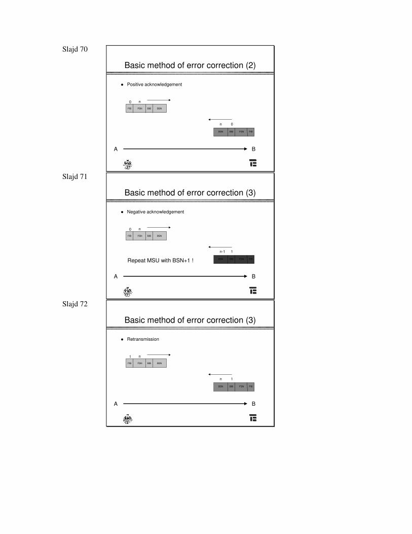
Basic method of error correction (2)
� Positive acknowledgement
BSN
BSN
BIB
BIB
FSNFIB
FIBFSN
n0
n 0
A B
Slajd 71
Basic method of error correction (3)
� Negative acknowledgement
BSN
BSN
BIB
BIB
FSNFIB
FIBFSN
n0
n-1 1
A B
Repeat MSU with BSN+1 !
Slajd 72
Basic method of error correction (3)
� Retransmission
BSN
BSN
BIB
BIB
FSNFIB
FIBFSN
n1
n 1
A B
Slajd 73 Preventive cyclic retransmission
method
� non-compelled, positive/negative acknowledgement,cyclic retransmission, forward error correction system
� transmitted signal unit is retained at the transmitting end terminal - until receiving positive acknowledgement
� when there are no new signal units to be transmitted- all yet not positively acknowledged units are again retransmitted cyclically
Slajd 74 Preventive cyclic retransmission
method - abnormal situation
� When the number of unacknowledged MSU’s exceeds thresholds - error correction is not sufficientto be done by cyclic retransmission
� forced retransmission is invoked: transmission of newMSU is stopped and all unacknowledged MSUs are retransmitted
� forced retransmission continue until the counts of unacknowledged MSUs and octets are below specific threshold value
� threshold value enables to control link performance
Slajd 75
Initial alignment
� Used after “switch-on” and during restoration after a link failure,
� based on compelled exchange of statusinformation between two signalling points.
Slajd 76
Signalling link error monitoring
� signal unit error rate monitor - used when signalling link is in service - provides one of the criterion toconsider link to be out of service» based on a signal unit error counter incremented and
decremented by “leaky bucket” method» during loss of alignement, the signal error rate monitor is
incremented proportionally to the length of period of alignment loss
� alignment error rate monitor - employed when the link is in proving state » based on linear count of signal unit errors
Slajd 77
Signal unit error rate monitor
� Based on a signal unit error counter� Each errored unit the counter is increased by
one, for each 256 signal units received(errored or not), a positive count is decremented by 1
� When he counter reaches value 64 an excessive error rate indication is sent to level3 - signalling link is in the out-of-servicestate
Slajd 78
Signal unit error rate monitor
� When more than six consecutive 1s are received or the maximum length of a signal unit is exceeded -loss of alignment occurs and error rate monitor enters an octet-counting mode
� Being in octet counting mode error rate monitorincrements the counter every 16 octets received
� Octet counting mode is changed back to alignment mode when the first correct signal unit is detected
Slajd 79
Alignment error rate monitor
� It is a linear counter that is operated during alignment proving periods
� The counter is set to zero at start of a proving periodand the count is incremented by 1 for each signal unit received (or after each 16 octets in the octet counting mode)
� The proving period is aborted when the threshold forthe the alignment error rate monitor is exceeded before the end proving-period
Slajd 80
Flow control
� Initiated when receiving end detects congestion� receiving terminal notifies transmitting end about
congestion by sending approppriate link statussignal unit
� no acknowledgements of incoming signal units� during congestion, transmitting end is periodically
informed about that state� too long congestion period causes link to be indicated
as failed (3 to 6 s)
Slajd 81 Flow control
Signalling Indication Processor Outage
� Signalling Indication Processor Outage (SIPO) is sent by level 2 whenever an explicit indication is sent from level 3 or there is recognition of level 3 failure
� SIPO informs far end that signalling messages cannot be transferred to level 3 (and above)
� The far end level 2 sends fill-in-signal units and inform its level 3 of SIPO condition
� The far end level 3 reroutes traffic according tosignalling network management procedures
Slajd 82
Link state control function
� provides directives to the other signalling link functions (switching function)
Slajd 83
Network layer issues for SS7
Slajd 84
Network layer issues
� Network management� Message handling processes� Message routing� Traffic management� Flow control� Failure recovery
Slajd 85
Signalling network functions (level 3)
� Correspond to the lower sublayer of the OSI’s network layer
� provide procedures for the transfer of messages between signalling points
� two basic categories:» signalling message handling» signalling network management
Slajd 86
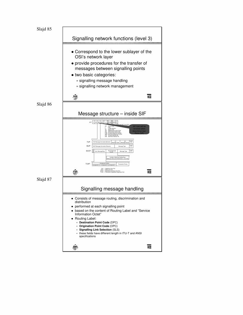
Message structure – inside SIF
Check BitsgFlag
CK
Length Indicator
BSN
Status Field
SIF SIO LI FSN BSN FCKFBIB
FIB
TUP Message Information Elements Message Type Message GroupLabel
BH1 H0
ISUP Message Information Elements Message TypeLabel
C
User Message/Data Header Message TypeLabel
DSCCP MessageE
OP
Includes Called And Calling PartyAdresses And Local References* (*CO Only)
Transaction PortionComponent n Component 2 Component 1
Component Portion
Signaling Information FieldService Information FieldForward Sequence NumberBackward Sequence NumberForward Indicator BitBackward Indicator Bit
FLISFSIFSIOFSN
FIBBIB
First Bit Transmitted
TUP
ISUP
MTP
SCCP
TCAP
TUP = Telephone User PartISUP = ISDN User Part
SCCP = Signaling Connection User PartTCAP = Transaction Capabilities Application Part
SIF field will be revisited when describing User
Parts (UP)
Slajd 87
Signalling message handling
� Consists of message routing, discrimination and distribution
� performed at each signalling point� based on the content of Routing Label and “Service
Information Octet”� Routing Label:
» Destination Point Code (DPC)» Origination Point Code (OPC)» Signalling Link Selection (SLS)» these fields have different length in ITU-T and ANSI
specifications
Slajd 88
Signalling network functions
Testing and Maintenance (MTP)Signalling Message Flow Indications and Controls
Signaling Network Functions
Signaling Message Handling
Level 4 Level 3
MTP
Level 2
MessageDiscrimination
Signaling Network Management
User Parts MessageTransfer
Part
SignallingLink
Management
Signalling
ManagementRoute
TrafficSignalling
Management
Message Distribution
MessageRouting
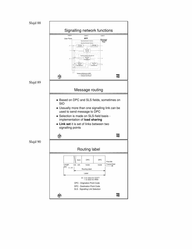
Slajd 89
Message routing
� Based on DPC and SLS fields, sometimes on SIO
� Ussually more than one signalling link can beused to send message to DPC
� Selection is made on SLS-field basis -implementation of load sharing
� Link set it is set of links between two signalling points
Slajd 90
Routing label
SLS OPC DPC
(bit)0/3 4/5 14/2414/24
n × 8
k/l: k is value for CCITTl is value for ANSI
First BitTransmitted
Label
Routing label
Length
OPC - Origination Point Code
DPC - Destination Point CodeSLS - Signalling Link Selection
Slajd 91
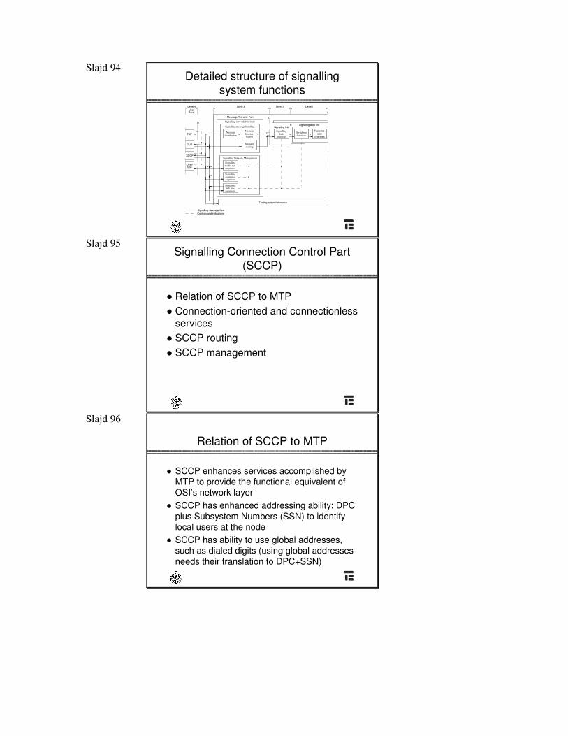
Load sharing
� chooses among links belonging to link set� the objective of load sharing is to spread the load, to
keep it balanced� can be done over links in the same link set or over
links not belonging to the same link set� collection of link sets used by load sharing is called a
combined link set� load sharing do not preserve sequence of messages,
so when this is necessary, the SLS field should bekept the same
Slajd 92
How SLS field works ?
A
B D G
C E H
I
xx11
xx00
SLS=xxx1
xxx0
xx01
xx10
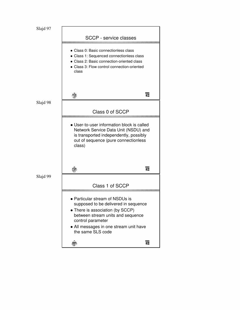
Slajd 93 General structure of signalling
system functions
Signallingmessagehandling
Signalling networkfunctions
Signallingnetwork
management
Signallinglink
functions
TUP
Other
DUP
type
Signallingdatalink
Signalling link
Message Transfer Part
Testing and maintenance
D C
B
A
Level 4 Level 3 Level 2 Level 1UserParts
Signalling message flowControls and indications
TUP Telephone User PartDUP Data User Part
Slajd 94 Detailed structure of signalling
system functions
Signalling message handling
Signallinglink
functionsTUP
DUP
Othertype
Signalling link
Message Transfer Part
Testing and maintenance
C
B
A
Level 3 Level 2 Level 1Level 4UserParts
Signalling message flowControls and indications
Messagediscrimi-
nation
Switchingfunctions
Signalling data link
Messagedistribution
Signalling network functions
Signallingtraffic ma-nagemnet
Signallingroute ma-nagement
Signallinglink ma-
nagement
Signalling Network ManagementSCCP
D
Messagerouting
Transmis-sion
channels
Slajd 95 Signalling Connection Control Part
(SCCP)
� Relation of SCCP to MTP� Connection-oriented and connectionless
services� SCCP routing� SCCP management
Slajd 96
Relation of SCCP to MTP
� SCCP enhances services accomplished by MTP to provide the functional equivalent of OSI’s network layer
� SCCP has enhanced addressing ability: DPC plus Subsystem Numbers (SSN) to identify local users at the node
� SCCP has ability to use global addresses,such as dialed digits (using global addresses needs their translation to DPC+SSN)
Slajd 97
SCCP - service classes
� Class 0: Basic connectionless class� Class 1: Sequenced connectionless class� Class 2: Basic connection-oriented class� Class 3: Flow control connection-oriented
class
Slajd 98
Class 0 of SCCP
� User-to-user information block is called Network Service Data Unit (NSDU) and is transported independently, possibly out of sequence (pure connectionless class)
Slajd 99
Class 1 of SCCP
� Particular stream of NSDUs is supposed to be delivered in sequence
� There is association (by SCCP)between stream units and sequence control parameter
� All messages in one stream unit have the same SLS code
Slajd 100
Class 2 of SCCP
� Bidirectional transfer of NSDUs is done through virtual circuit
� Messages belonging to the same signalling connection have the same SLS field
� Segmentation and reassembly capability is provided (when NSDU is longer than 255octets)
Slajd 101
Class 3 of SCCP
� Capabilities of class 2 are supported with addition of flow control
� Detection of message loss and mis-sequencing is provided
� There is notification of higher layers about message loss and mis-sequencing
Slajd 102
SCCP functions
SCCP
Connection-OrientedControl(SCOC)
SCCPConnectionlessControl (SCLC)
SOR
SOG
SSA
SSP
SST
CO MessageSCCP
Routing Control
SCCP
(SCRC)
Routing
Failure
FailureRouting
CL Message
SCCP Management (SCMG)
Message Received forUnavailable Local SS
SCCPSCCP Users MTP
N-Connect RequestN-Connect ResponseN-Data RequestN-Exped. Data RequestN-Data Acknowledgment RequestN-Disconnect RequestN-Reset RequestN-Reset ResponseN-Inform Request
N-Connect IndicationN-Connect ConfirmationN-Data IndicationN-Exped. Data IndicationN-Data Acknowledgment IndicationN-Disconnected Indication
N-Reset ConfirmationN-Inform Indication
N-Reset Indication
Request Type 1Request Type 2Reply
N-Unitdate RequestN-Unitdate IndicationN-Notice Indication
N-Coordination RequestN-Coordination ResponseN-State Request
N-Coordination IndicationN-Coordination ConfirmationN-State IndicationN-PC State Indication
MTP - Transfer Indication
MTP - Transfer Request
MTP - Pause Indication
MTP - Resume Indication
MTP - Status Indication

Slajd 103
Signalling network structures
Slajd 104
Basic SS7 network structure
STP STP
STP STP
SP
SP
SP - Signalling Point
STP - Signalling Transfer Point
Slajd 105
Basic structure - mesh-type
� Mesh type or quad-type� The STPs are combined (“mated”) on a pairwise
basis� Mesh-type network has 100% redundacy (any single
failure causes traffic to be diverted to alternative paths)
� Each component should be engineered in such wayto allow twice its peak load
� There is necessity to fulfil diversity criterion: split of quad pairs into different physical transmission paths
Slajd 106
Alternate signalling network structure
STP 1
STP 2
C
A B
Associated Associated
� Mix of associated andquasi-associated signalling modes
� Associated signalling mode can be used as first choice route
� Quasi-associated signalling mode can beused as backup in case the associated path fails
Slajd 107
Generalization of mesh-networkCluster
(1,3)
Cluster(2,4)
Cluster(3,4)
Cluster(2,3)
Cluster(1,2)
Cluster(4,5)
Cluster(4,6)
Cluster(3,5)
Cluster(2,6)
Cluster(1,6)
Cluster(1,5)
Cluster(5,6)
STP 2
STP 3STP 1
STP 6 STP 4
STP 5
Cluster(4,6)
Slajd 108
Generalization of mesh-network
� Backbone network of fully connected STPs� Clusters of offices (SPs) are connected to
different pairs of STPs� When STP fails - its load is split to number of
STPs� When signalling link fails - also split of traffic
Slajd 109
SS7 node codes
Slajd 110
Signalling Area Network Code (SANC)
� Country designations were decided before wide deployment of IP networks
� ITU Point Code Format is different than the ANSI (North American)
Signalling Point IDNetwork IDZone ID
3 bits 8 bits 3 bits
Slajd 111
ITU Zone IDs
South America7
Africa6
South Asia, Australia, New Zealand
5
Middle East and Asia4
North America, Mexico, the Caribean, Greenland
3
Europe2
Geographical RegionZone ID
Slajd 112
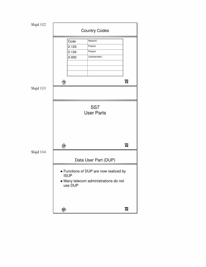
Country Codes
Liechtenstein 2-000
Poland2-134
Poland2-120
NetworkCode
Slajd 113
SS7User Parts
Slajd 114
Data User Part (DUP)
� Functions of DUP are now realized by ISUP
� Many telecom administrations do notuse DUP
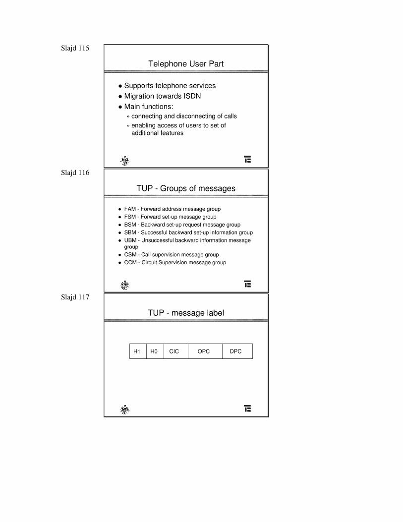
Slajd 115
Telephone User Part
� Supports telephone services� Migration towards ISDN� Main functions:
» connecting and disconnecting of calls» enabling access of users to set of
additional features
Slajd 116
TUP - Groups of messages
� FAM - Forward address message group� FSM - Forward set-up message group� BSM - Backward set-up request message group� SBM - Successful backward set-up information group� UBM - Unsuccessful backward information message
group� CSM - Call supervision message group� CCM - Circuit Supervision message group
Slajd 117
TUP - message label
DPCOPCCICH0H1
Slajd 118
Message structure
Check BitsgFlag
CK
Length Indicator
BSN
Status Field
SIF SIO LI FSN BSN FCKFBIB
FIB
TUP Message Information Elements Message Type Message GroupLabel
BH1 H0
ISUP Message Information Elements Message TypeLabel
C
User Message/DataHeader
Message TypeLabel
DSCCP MessageE
OP
Includes Called And Calling PartyAdresses And Local References* (*CO Only)
Transaction PortionComponent n Component 2 Component 1
Component Portion
Signaling Information FieldService Information FieldForward Sequence NumberBackward Sequence NumberForward Indicator BitBackward Indicator Bit
FLISFSIFSIOFSN
FIBBIB
First Bit Transmitted
TUP
ISUP
MTP
SCCP
TCAP
TUP = Telephone User PartISUP = ISDN User Part
SCCP = Signaling Connection User PartTCAP = Transaction Capabilities Application Part
Slajd 119
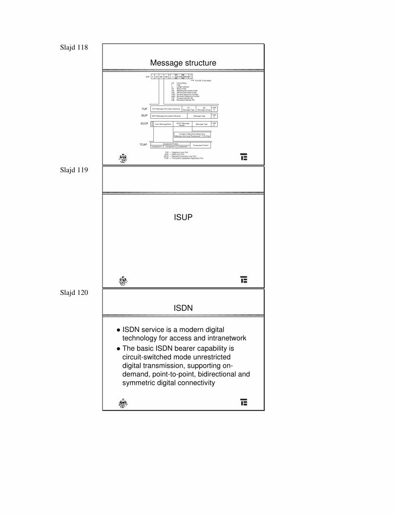
ISUP
Slajd 120
ISDN
� ISDN service is a modern digital technology for access and intranetwork
� The basic ISDN bearer capability is circuit-switched mode unrestricted digital transmission, supporting on-demand, point-to-point, bidirectional and symmetric digital connectivity
Slajd 121
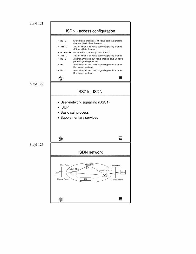
ISDN - access configuration
� 2B+D two 64kbit/s channels + 16 kbit/s packet/signalling channel (Basic Rate Access)
� 23B+D 23 x 64 kbit/s + 16 kbit/s packet/signalling channel (Primary Rate Access)
� n x 64 + D n x 64 kbit/s channels (n from 1 to 23)� 30B+D 30 x 64 kbit/s + 64 kbit/s packet/signalling channel � H0+D A nonchannelized 384 kbit/s channel plus 64 kbit/s
packet/signalling channel� H11 A nonchannelized 1.536 (signalling within another
D-channel interface)� H12 A nonchannelized 1.920 (signalling within another
D-channel interface)
Slajd 122
SS7 for ISDN
� User-network signalling (DSS1)� ISUP� Basic call process� Supplementary services
Slajd 123
ISDN network
SS7
User User
User Plane
Control Plane
User Plane
Control Plane
switch ISDN
switch ISDN
switch ISDN
Slajd 124
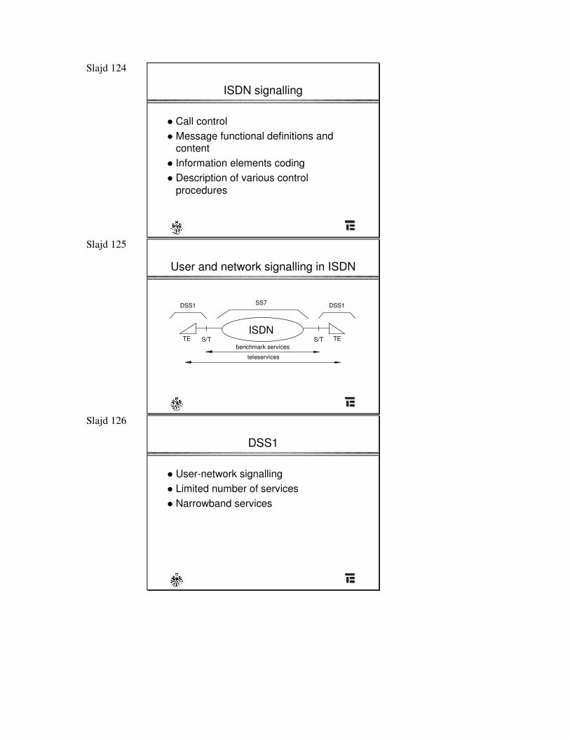
ISDN signalling
� Call control� Message functional definitions and
content� Information elements coding� Description of various control
procedures
Slajd 125
User and network signalling in ISDN
SS7 DSS1DSS1
S/T S/TISDN
benchmark services
teleservices
TE TE
Slajd 126
DSS1
� User-network signalling� Limited number of services� Narrowband services
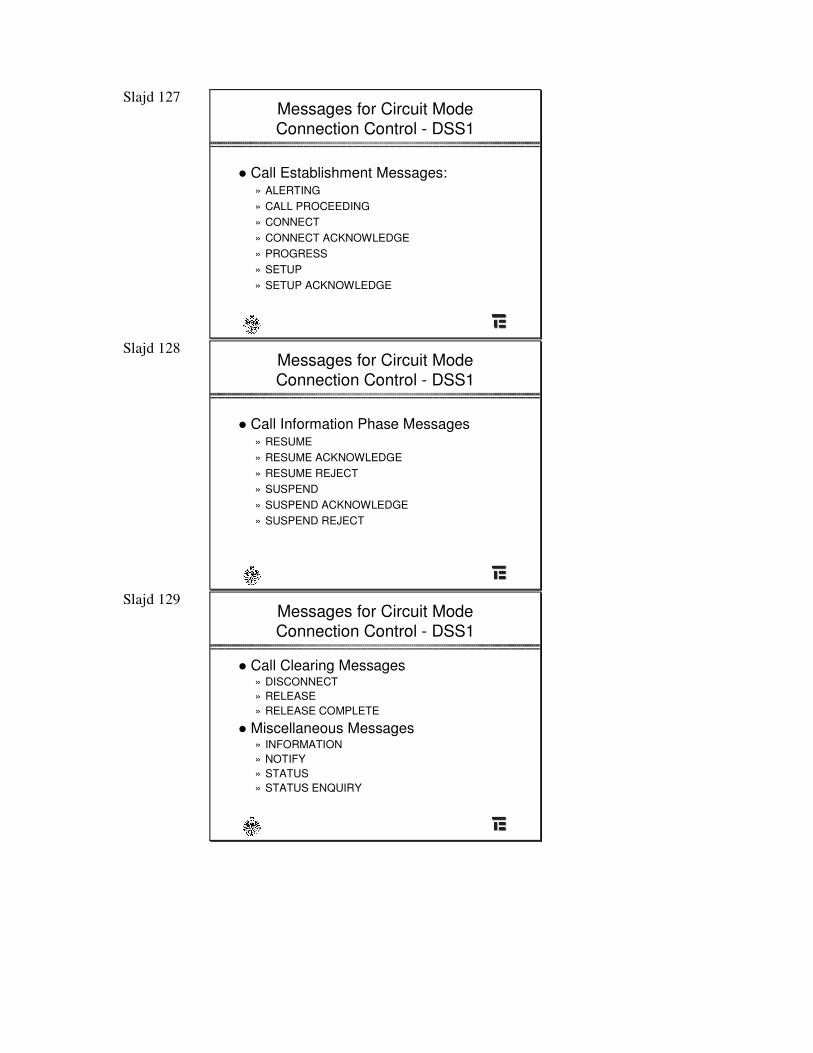
Slajd 127 Messages for Circuit Mode Connection Control - DSS1
� Call Establishment Messages:» ALERTING» CALL PROCEEDING» CONNECT» CONNECT ACKNOWLEDGE» PROGRESS» SETUP» SETUP ACKNOWLEDGE
Slajd 128 Messages for Circuit Mode Connection Control - DSS1
� Call Information Phase Messages» RESUME» RESUME ACKNOWLEDGE» RESUME REJECT» SUSPEND» SUSPEND ACKNOWLEDGE» SUSPEND REJECT
Slajd 129 Messages for Circuit Mode Connection Control - DSS1
� Call Clearing Messages» DISCONNECT» RELEASE» RELEASE COMPLETE
� Miscellaneous Messages» INFORMATION» NOTIFY» STATUS» STATUS ENQUIRY
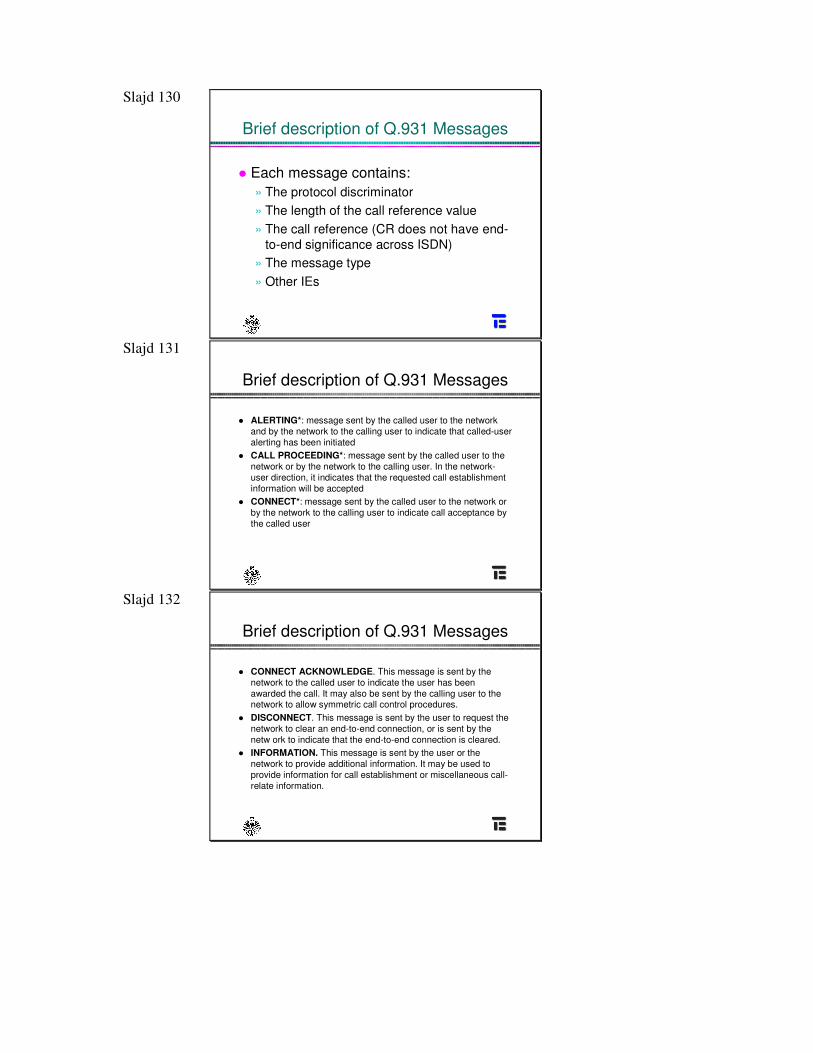
Slajd 130
Brief description of Q.931 Messages
� Each message contains:» The protocol discriminator» The length of the call reference value» The call reference (CR does not have end-
to-end significance across ISDN)» The message type» Other IEs
Slajd 131
Brief description of Q.931 Messages
� ALERTING*: message sent by the called user to the network and by the network to the calling user to indicate that called-user alerting has been initiated
� CALL PROCEEDING*: message sent by the called user to the network or by the network to the calling user. In the network-user direction, it indicates that the requested call establishmentinformation will be accepted
� CONNECT*: message sent by the called user to the network orby the network to the calling user to indicate call acceptance bythe called user
Slajd 132
Brief description of Q.931 Messages
� CONNECT ACKNOWLEDGE. This message is sent by the network to the called user to indicate the user has been awarded the call. It may also be sent by the calling user to the network to allow symmetric call control procedures.
� DISCONNECT. This message is sent by the user to request the network to clear an end-to-end connection, or is sent by the netw ork to indicate that the end-to-end connection is cleared.
� INFORMATION. This message is sent by the user or the network to provide additional information. It may be used toprovide information for call establishment or miscellaneous call-relate information.
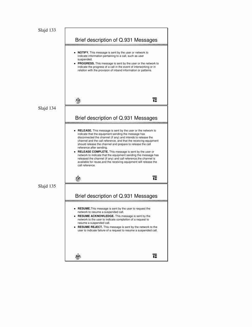
Slajd 133
Brief description of Q.931 Messages
� NOTIFY. This message is sent by the user or network toindicate information pertaining to a call, such as user suspended.
� PROGRESS. This message is sent by the user or the network toindicate the progress of a call in the event of interworking or in relation with the provision of inband information or pattems.
Slajd 134
Brief description of Q.931 Messages
� RELEASE. This message is sent by the user or the network toindicate that the equipment sending the message has disconnected the channel (if any) and intends to release the channel and the call reference, and that the receiving equipment should release the channel and prepare to release the call reference after sending.
� RELEASE COMPLETE. This message is sent by the user or network to indicate that the equipment sending the message has released the channel (if any) and call reference,the channel is available for reuse,and the receiving equipment will release the call reference.
Slajd 135
Brief description of Q.931 Messages
� RESUME.This message is sent by the user to request the network to resume a suspended call.
� RESUME ACKNOWLEDGE. This message is sent by the network to the user to indicate completion of a request to resume a suspended call.
� RESUME REJECT. This message is sent by the network to the user to indicate failure of a request to resume a suspended call.
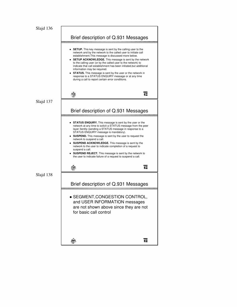
Slajd 136
Brief description of Q.931 Messages
� SETUP. This key message is sent by the calling user to the network and by the network to the called user to initiate callestablishment.This message is discussed more below.
� SETUP ACKNOWLEDGE. This message is sent by the networkto the calling user (or by the called user to the network) toindicate that call establishment has been initiated,but additional information may be required.
� STATUS. This message is sent by the user or the network in response to a STATUS ENQUIRY message or at any time during a call to report certain error conditions.
Slajd 137
Brief description of Q.931 Messages
� STATUS ENQUIRY. This message is sent by the user or the network at any time to solicit a STATUS message from the peer layer 3entity (sending a STATUS message in response to a STATUS ENQUIRY message is mandatory).
� SUSPEND. This message is sent by the user to request the network to suspend a call.
� SUSPEND ACKNOWLEDGE. This message is sent by the network to the user to indicate completion of a request tosuspend a call.
� SUSPEND REJECT. This message is sent by the network tothe user to indicate failure of a request to suspend a call.
Slajd 138
Brief description of Q.931 Messages
� SEGMENT,CONGESTION CONTROL,and USER lNFORMATION messages are not shown above since they are not for basic call control
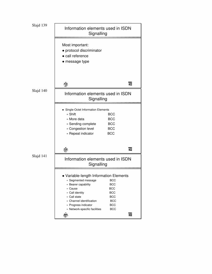
Slajd 139 Information elements used in ISDN
Signalling
Most important:� protocol discriminator� call reference� message type
Slajd 140 Information elements used in ISDN
Signalling
� Single-Octet Information Elements
» Shift BCC» More data BCC» Sending complete BCC» Congestion level BCC» Repeat indicator BCC
Slajd 141 Information elements used in ISDN
Signalling
� Variable-Iength Information Elements» Segmented message BCC» Bearer capability BCC» Cause BCC» Call identity BCC» Call state BCC» Channel identification BCC» Progress indicator BCC» Network-specific facilities BCC
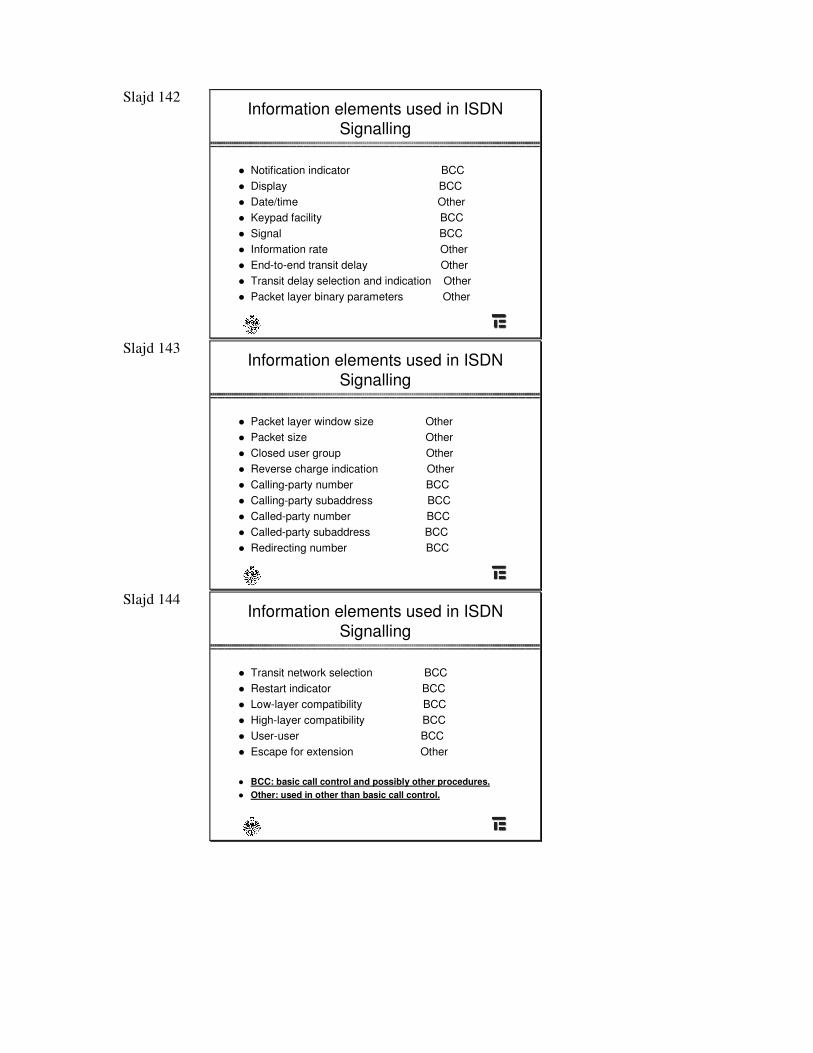
Slajd 142 Information elements used in ISDN
Signalling
� Notification indicator BCC� Display BCC� Date/time Other� Keypad facility BCC� Signal BCC� Information rate Other� End-to-end transit delay Other� Transit delay selection and indication Other� Packet layer binary parameters Other
Slajd 143 Information elements used in ISDN
Signalling
� Packet layer window size Other� Packet size Other� Closed user group Other� Reverse charge indication Other� Calling-party number BCC� Calling-party subaddress BCC� Called-party number BCC� Called-party subaddress BCC� Redirecting number BCC
Slajd 144 Information elements used in ISDN
Signalling
� Transit network selection BCC� Restart indicator BCC� Low-layer compatibility BCC� High-layer compatibility BCC� User-user BCC� Escape for extension Other
� BCC: basic call control and possibly other procedures.� Other: used in other than basic call control.
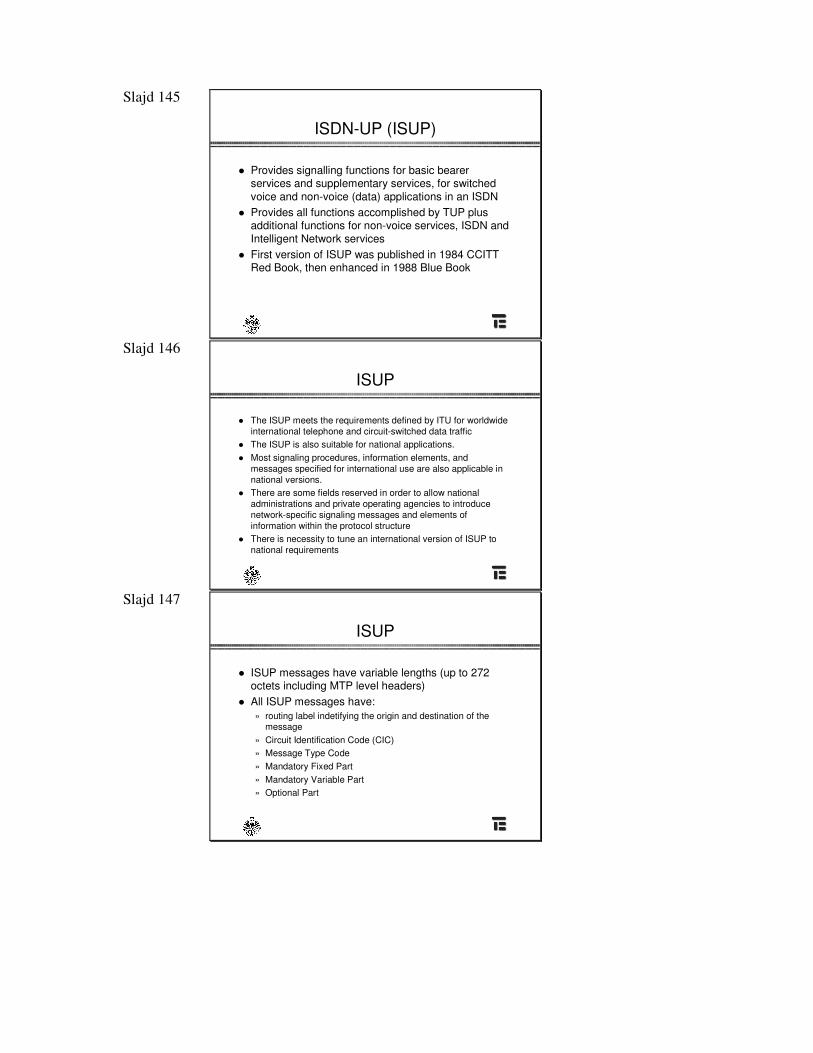
Slajd 145
ISDN-UP (ISUP)
� Provides signalling functions for basic bearer services and supplementary services, for switched voice and non-voice (data) applications in an ISDN
� Provides all functions accomplished by TUP plusadditional functions for non-voice services, ISDN and Intelligent Network services
� First version of ISUP was published in 1984 CCITT Red Book, then enhanced in 1988 Blue Book
Slajd 146
ISUP
� The ISUP meets the requirements defined by ITU for worldwide international telephone and circuit-switched data traffic
� The ISUP is also suitable for national applications. � Most signaling procedures, information elements, and
messages specified for international use are also applicable in national versions.
� There are some fields reserved in order to allow national administrations and private operating agencies to introduce network-specific signaling messages and elements of information within the protocol structure
� There is necessity to tune an international version of ISUP tonational requirements
Slajd 147
ISUP
� ISUP messages have variable lengths (up to 272octets including MTP level headers)
� All ISUP messages have:» routing label indetifying the origin and destination of the
message» Circuit Identification Code (CIC)» Message Type Code » Mandatory Fixed Part» Mandatory Variable Part» Optional Part
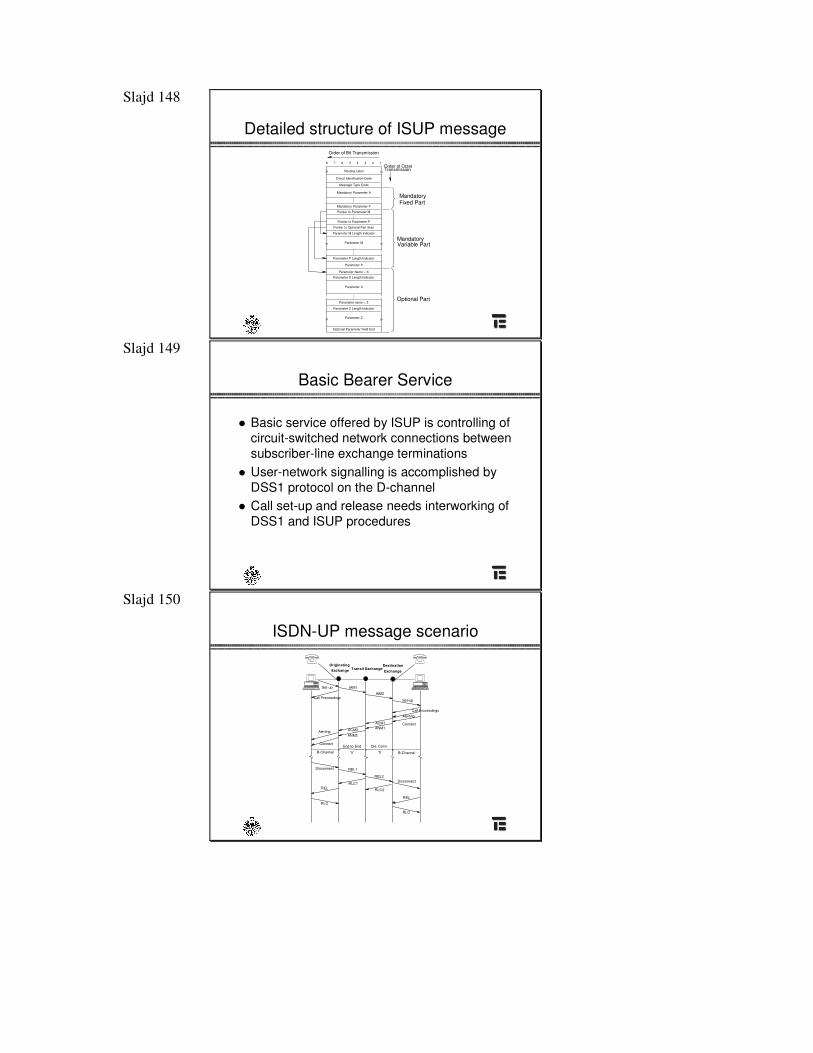
Slajd 148
Detailed structure of ISUP message Order of Bit Transmission
Routing Label
Circuit Identification Code
Message Type Code
Mandatory Parameter A
Mandatory Parameter F
Pointer to Parameter M
Pointer to Parameter P
Pointer to Optional Part Start
Parameter M Length Indicator
Parameter M
Parameter P Length Indicator
Parameter P
Parameter Name = X
Parameter X Length Indicator
Parameter X
Parameter name = Z
Parameter Z Length Indicator
Parameter Z
Optional Parameter Field End
18 7 6 5 4 3 2
» »
» »
» »
Order of OctetTransmission
MandatoryFixed Part
MandatoryVariable Part
Optional Part
Slajd 149
Basic Bearer Service
� Basic service offered by ISUP is controlling of circuit-switched network connections between subscriber-line exchange terminations
� User-network signalling is accomplished by DSS1 protocol on the D-channel
� Call set-up and release needs interworking ofDSS1 and ISUP procedures
Slajd 150
ISDN-UP message scenario
Set-up
Call ProceedingsAlerting
ConnectACM1ANM1ACM2
ANM2Alerting
Connect
Set-up
Call Proceedings
Transit ExchangeOriginatingExchange
Destination
Exchange
B-Channel
End-to-End
'a' 'b' B-Channel
Ckt. Conn.
DisconnectREL2
RLC2
REL1
RLC1
Disconnect
REL
RLC
REL
RLC
IAM1
IAM2
Slajd 151
Supplementary Services for ISDN
Slajd 152
Supplementary services
� Supplementary services add more functionality to calls established in ISDNnetwork
� They invoke some functions which areterminal-specific
� Typical supplementary services are: user-to-user signalling, closed-user group, call forwarding, calling line identification, etc.
Slajd 153 Number Identification Supplementary
Services
� Calling line identification presentation (CLIP)� Calling line identification restriction (CLIR)� Connected line identification presentation (COLP)� Connected line identification restriction (COLR)� Direct Inward Dialing Service� Multiple Subscriber Number (MSN Supplementary
Service� Malicious Call Identification ( MCID) Supplementary
Services� Sub-addressing Supplementary Services (SUB)
Slajd 154
Supplementary services (details)
� Q.731� Stage 3 description for number identification supplementary
services using signalling system No. 7
� Clause 1 (02/92) Direct-dialling-in (DDI)� Clause 3 (1993) Calling line identification presentation (CLIP)� Clause 4 (1993) Calling line identification restriction (CLIR)� Clause 5 (1993) Connected line identification presentation
(COLP)� Clause 6 (1993) Connected line identification restriction
(COLR)� Clause 8 (02/92) Sub-addressing (SUB)
Slajd 155
DDI
� Direct-Dialling-In (DDI) enables a user to directly call another user on an integrated services private branch exchange or other private system without attendant intervention.
� This supplementary service shall be based on the use of theISDN number. At least the significant part of the ISDN number shall be passed to the private ISDN, in order to progress the callto the destination.
� Direct-Dialling-In shall apply to public ISDNs having either aclosed or an open numbering plan.
� This service shall be provided/withdrawn after pre-arrangement with the service provider. The service provider shall allocate a set of ISDN numbers.
Slajd 156
MSU
� The Multiple Subscriber Number (MSN) supplementary service provides the possibility for assigning multiple numbers(not necessarily consecutive) to a single public or private interface. This enables the selection of one or multiple distinct terminals attached to the same interface. The service provider shall fix the length of the numbers to be transmitted to the user's installation. They may comprise the least significant digit up to the full integrated services digital network ISDN number (E.164)
Slajd 157
MSU
� Multiple Subscriber Number provides the possibility forassigning multiple integrated services digital network numbersto a single interface. For example, this service:» 1) allows dialling from a line connected to a public network
directly to terminals connected to a basic access which bassubscribed to Multiple Subscriber Number (e.g. in a passive bus configuration);
» 2) enables the network to determine which ISDN number is applicable on originating calls (e.g. for charging purposes, for notification to the called party and application forsupplementary services).
Slajd 158
MSU
� Administrations:» may not have knowledge or control over what is connected
to the basic access, e.g. an network termination 2 (NT2) or passive bus;
» may have different numbering methods;» may agree that common international terminal specifications
are desired.
Slajd 159
CLIP
� Calling Line Identifcation Presentation (CLIP) is asupplementary service offered to the called party which provides the calling party's ISDN-number, possibly with sub-address information, to the called party.
� When Calling Line ldentification Presentation is applicable and activated, the network provides the called party with the number of the calling party at call set-up on all incoming calls.
� The calling party number may be accompanied by a sub-address.The network should be capable of transmitting at least15 digits [maximum length of an integrated services digital network (ISDN) number]. In addition, if provided by the callingparty, the network should be capable of transmitting a sub-address.
Slajd 160
Sub-addressing
� The sub-addressing supplementary service allows tbe called(served) user to expand his addressing capacity beyond the onegiven by the ISDN number.
� A sub-address, if presented by a calling user, is delivered unaffected to the called (served) user. Only the
� served user defines tbe significance of tbe sub-address.Applications can be for example:» 1) to select or to prefer a specific terminal at tbe called
customer's termination;» 2) to invoke a specific process in a terminal at the called
customer's termination.� Tbe maximum size of the sub-address is 20 octets.
Slajd 161
Supplementary services
� Q.732� Stage 3 description for call offering supplementary services using
Signalling System No. 7� Clause 2 (1993) Call diversion services � Clause 3 (1993) Call forwarding no answer � Clause 4 (1993) Call forwarding unconditional � Clause 5 (1993) Call deflection
Slajd 162
Call forwarding unconditional
� Call forwarding unconditional permits a "served user" to have the network send to another number all incoming calls for the served user's ISDN number (or just those associated with aspecified basic service).
� The served user's originating service is unaffected. If this service is activated, calls are forwarded no matter what the condition of the termination. Other call forwarding services provide for call forwarding based on condition, e.g. Call Forwarding Busy and Call Forwarding No Reply.
� The forwarded-to number is registered with the network for usefor all calls.
Slajd 163
Supplementary services
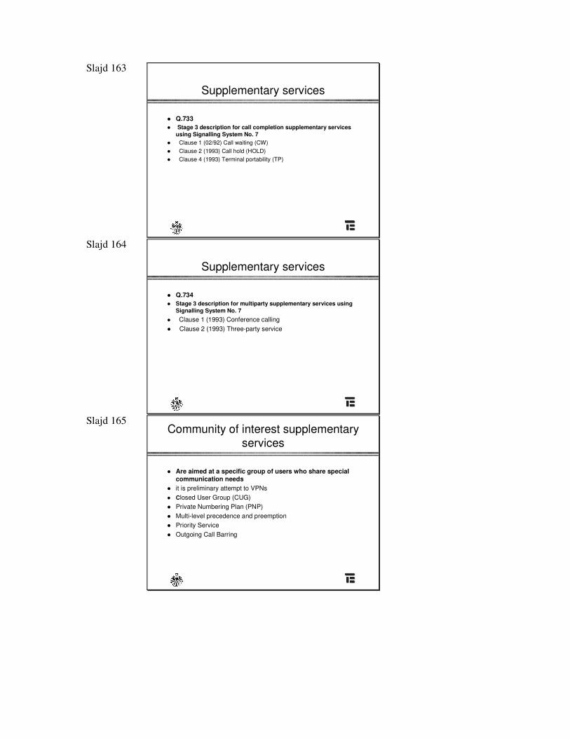
� Q.733� Stage 3 description for call completion supplementary services
using Signalling System No. 7� Clause 1 (02/92) Call waiting (CW)� Clause 2 (1993) Call hold (HOLD)� Clause 4 (1993) Terminal portability (TP)
Slajd 164
Supplementary services
� Q.734� Stage 3 description for multiparty supplementary services using
Signalling System No. 7� Clause 1 (1993) Conference calling � Clause 2 (1993) Three-party service
Slajd 165 Community of interest supplementary
services
� Are aimed at a specific group of users who share special communication needs
� it is preliminary attempt to VPNs� Closed User Group (CUG)� Private Numbering Plan (PNP)� Multi-level precedence and preemption � Priority Service � Outgoing Call Barring
Slajd 166
Supplementary services (details)
� Q.735� Stage 3 description for community of interest supplementary
services using SS No. 7� Clause 1 (1993) Closed user group (CUG)� Clause 3 (1993) Multi-level precedence and preemption � Q.737� Stage 3 description for additional information transfer
supplementary services using SS No. 7� Clause 1 (1993) User-to-user signalling (UUS)
Slajd 167
Closed User Group
� A closed user group consists of a group of users who have a restricted access arrangements and features.
� A user can be a member of one or more CUGs. � Restriction categories:
» Call permitted only within the CUG» Calls within the CUG and incoming calls only from users outside the CUG» Calls within the CUG and outgoing calls only to users outside the CUG» Calls within the CUG and both incoming and outgoing calls to users outside
the CUG
� Typically if a user is a member of many CUGs, one CUG is registered with the network as preferential CUG.
Slajd 168
List of ISUP Messages
� (38 messages)� Address Complete Message (ACM). A message sent in the
backward direction indicating that all the address signals required for routing the call to the called party have been received.
� Answer Message (ANM). A message sent in the backward direction indicating that the call has been answered. Insemiautomatic working, this message has a supervisory function. In automatic working, this message is used in conjunction with charging information in order to: » (1) start metering the charge to the calling subscriber» (2) start measurement of call duration for international
accounting purposes.
Slajd 169
List of ISUP Messages
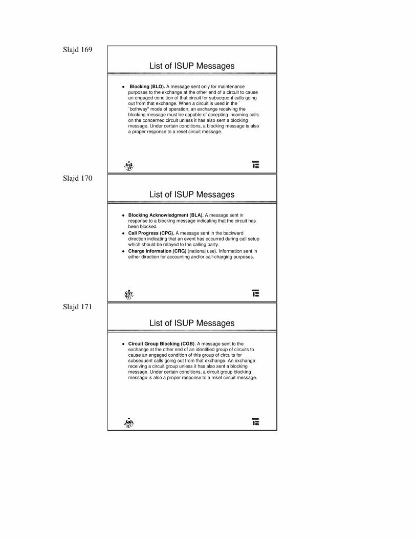
� Blocking (BLO). A message sent only for maintenance purposes to the exchange at the other end of a circuit to cause an engaged condition of that circuit for subsequent calls going out from that exchange. When a circuit is used in the ` `bothway'' mode of operation, an exchange receiving the blocking message must be capable of accepting incoming callson the concerned circuit unless it has also sent a blocking message. Under certain conditions, a blocking message is alsoa proper response to a reset circuit message.
Slajd 170
List of ISUP Messages
� Blocking Acknowledgment (BLA). A message sent in response to a blocking message indicating that the circuit has been blocked.
� Call Progress (CPG). A message sent in the backward direction indicating that an event has occurred during call setup which should be relayed to the calling party.
� Charge Information (CRG) (national use). Information sent in either direction for accounting and/or call-charging purposes.
Slajd 171
List of ISUP Messages
� Circuit Group Blocking (CGB). A message sent to the exchange at the other end of an identified group of circuits tocause an engaged condition of this group of circuits forsubsequent calls going out from that exchange. An exchange receiving a circuit group unless it has also sent a blocking message. Under certain conditions, a circuit group blocking message is also a proper response to a reset circuit message.
Slajd 172
List of ISUP Messages
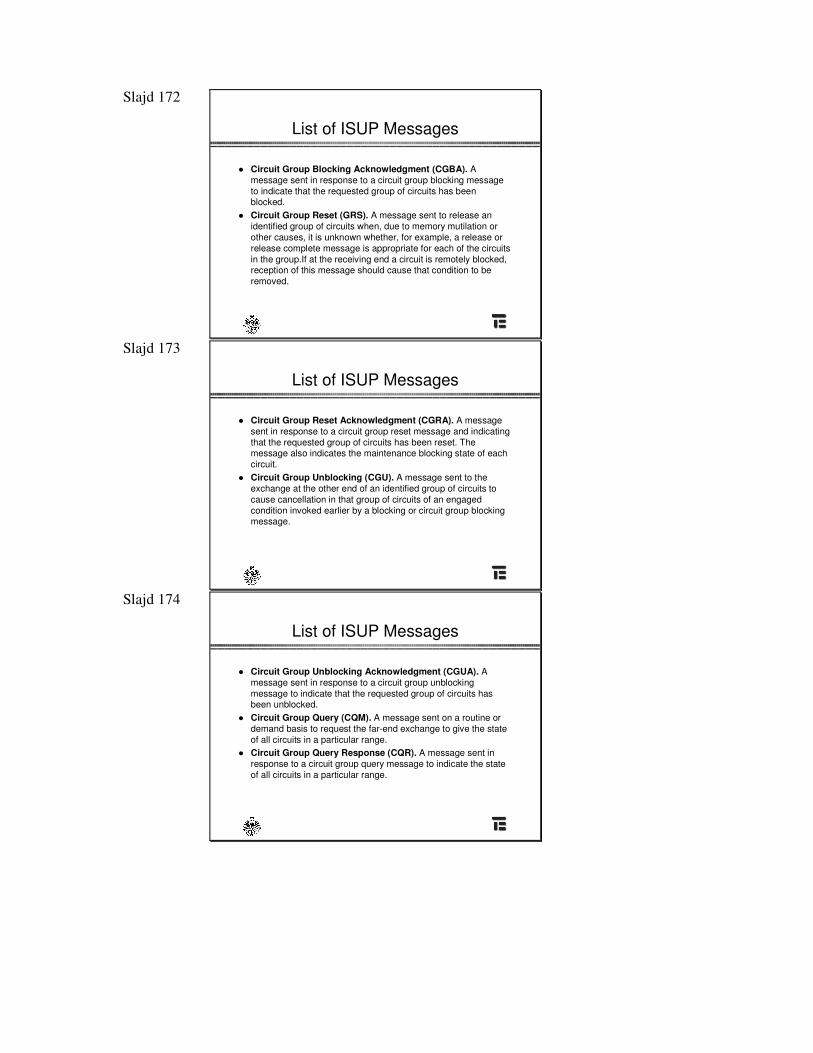
� Circuit Group Blocking Acknowledgment (CGBA). Amessage sent in response to a circuit group blocking messageto indicate that the requested group of circuits has been blocked.
� Circuit Group Reset (GRS). A message sent to release an identified group of circuits when, due to memory mutilation or other causes, it is unknown whether, for example, a release or release complete message is appropriate for each of the circuits in the group.If at the receiving end a circuit is remotely blocked,reception of this message should cause that condition to beremoved.
Slajd 173
List of ISUP Messages
� Circuit Group Reset Acknowledgment (CGRA). A message sent in response to a circuit group reset message and indicating that the requested group of circuits has been reset. The message also indicates the maintenance blocking state of each circuit.
� Circuit Group Unblocking (CGU). A message sent to the exchange at the other end of an identified group of circuits tocause cancellation in that group of circuits of an engaged condition invoked earlier by a blocking or circuit group blocking message.
Slajd 174
List of ISUP Messages
� Circuit Group Unblocking Acknowledgment (CGUA). Amessage sent in response to a circuit group unblocking message to indicate that the requested group of circuits has been unblocked.
� Circuit Group Query (CQM). A message sent on a routine or demand basis to request the far-end exchange to give the state of all circuits in a particular range.
� Circuit Group Query Response (CQR). A message sent in response to a circuit group query message to indicate the state of all circuits in a particular range.
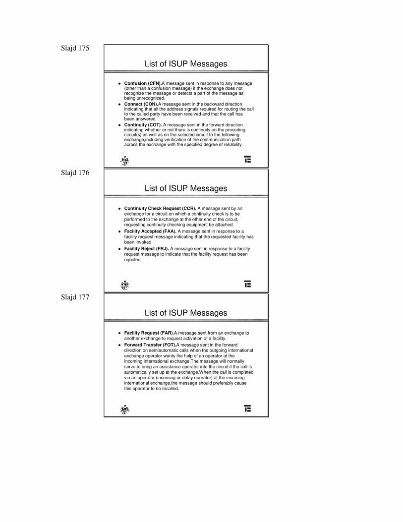
Slajd 175
List of ISUP Messages
� Confusion (CFN).A message sent in response to any message(other than a confusion message) if the exchange does notrecognize the message or detects a part of the message asbeing unrecognized.
� Connect (CON).A message sent in the backward direction indicating that all the address signals required for routing the callto the called party have been received and that the call has been answered.
� Continuity (COT). A message sent in the forward direction indicating whether or not there is continuity on the preceding circuit(s) as well as on the selected circuit to the following exchange,including verification of the communication path across the exchange with the specified degree of reliability.
Slajd 176
List of ISUP Messages
� Continuity Check Request (CCR). A message sent by an exchange for a circuit on which a continuity check is to beperformed to the exchange at the other end of the circuit,requesting continuity checking equipment be attached.
� Facility Accepted (FAA). A message sent in response to afacility request message indicating that the requested facility has been invoked.
� Facility Reject (FRJ). A message sent in response to a facility request message to indicate that the facility request has been rejected.
Slajd 177
List of ISUP Messages
� Facility Request (FAR).A message sent from an exchange toanother exchange to request activation of a facility.
� Forward Transfer (FOT).A message sent in the forward direction on semiautomatic calls when the outgoing international exchange operator wants the help of an operator at the incoming international exchange.The message will normally serve to bring an assistance operator into the circuit if the call is automatically set up at the exchange.When the call is completedvia an operator (incoming or delay operator) at the incoming international exchange,the message should preferably cause this operator to be recalled.
Slajd 178
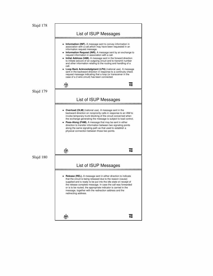
List of ISUP Messages
� Information (INF). A message sent to convey information in association with a call,which may have been requested in an information request message.
� Information Request (INR). A message sent by an exchange torequest information in association with a call.
� Initial Address (IAM). A message sent in the forward directionto initiate seizure of an outgoing circuit and to transmit number and other information relating to the routing and handling of acall.
� Loop Back Acknowledgment (LPA) (national use). A message sent in the backward direction in response to a continuity check request message indicating that a loop (or transceiver in the case of a 2-wire circuit) has been connected.
Slajd 179
List of ISUP Messages
� Overload (OLM) (national use). A message sent in the backward direction on nonpriority calls in response to an IAM toinvoke temporary trunk blocking of the circuit concerned when the exchange generating the message is subject to load control.
� Pass-Along (PAM). A message that may be sent in either direction to transfer information between two signaling points along the same signaling path as that used to establish aphysical connection between those two points.
Slajd 180
List of ISUP Messages
� Release (REL). A message sent in either direction to indicate that the circuit is being released due to the reason (cause)supplied and is ready to be put into the idle state on receipt of the release complete message. In case the call was forwarded or is to be routed, the appropriate indicator is carried in the message, together with the redirection address and the redirecting address.
Slajd 181
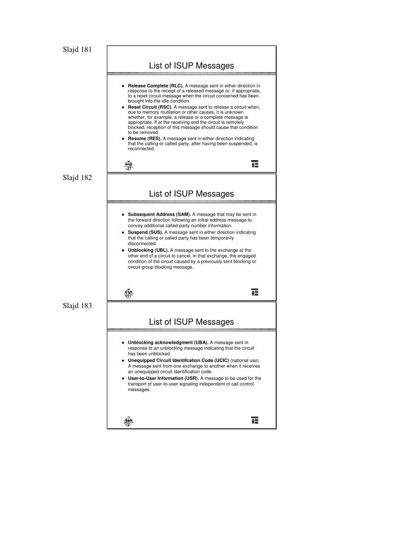
List of ISUP Messages
� Release Complete (RLC). A message sent in either direction in response to the receipt of a released message or, if appropriate, to a reset circuit message when the circuit concerned has been brought into the idle condition.
� Reset Circuit (RSC). A message sent to release a circuit when,due to memory mutilation or other causes, it is unknown whether, for example, a release or a complete message is appropriate. If at the receiving end the circuit is remotely blocked, reception of this message should cause that conditionto be removed.
� Resume (RES). A message sent in either direction indicating that the calling or called party, after having been suspended, is reconnected.
Slajd 182
List of ISUP Messages
� Subsequent Address (SAM). A message that may be sent in the forward direction following an initial address message toconvey additional called-party number information.
� Suspend (SUS). A message sent in either direction indicating that the calling or called party has been temporarily disconnected.
� Unblocking (UBL). A message sent to the exchange at the other end of a circuit to cancel, in that exchange, the engaged condition of the circuit caused by a previously sent blocking or circuit group blocking message.
Slajd 183
List of ISUP Messages
� Unblocking acknowledgment (UBA). A message sent in response to an unblocking message indicating that the circuit has been unblocked.
� Unequipped Circuit Identifcation Code (UCIC) (national use). A message sent from one exchange to another when it receives an unequipped circuit identification code.
� User-to-User Information (USR). A message to be used for thetransport of user-to-user signaling independent of call control messages.
Slajd 184 Information elements in ISUP
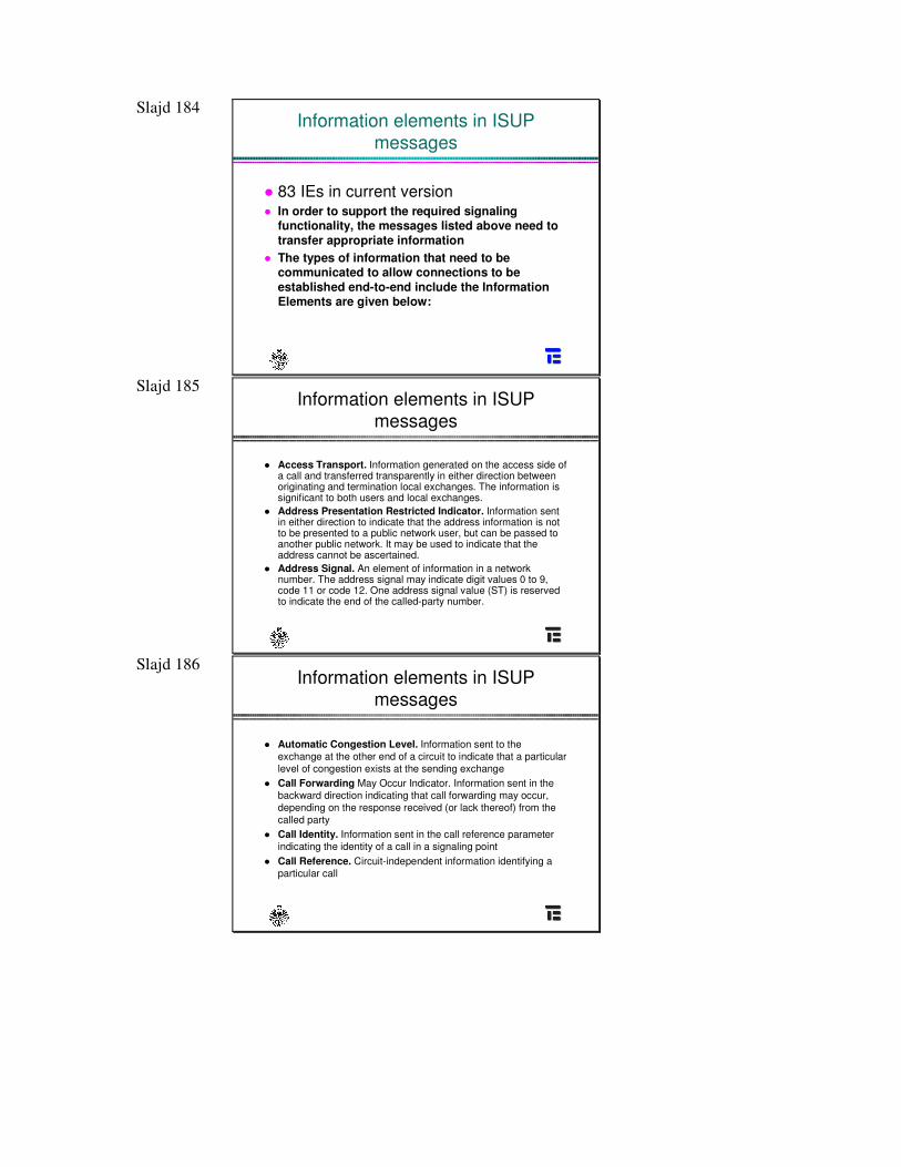
messages
� 83 IEs in current version� In order to support the required signaling
functionality, the messages listed above need to transfer appropriate information
� The types of information that need to becommunicated to allow connections to beestablished end-to-end include the Information Elements are given below:
Slajd 185 Information elements in ISUP
messages
� Access Transport. Information generated on the access side ofa call and transferred transparently in either direction between originating and termination local exchanges. The information is significant to both users and local exchanges.
� Address Presentation Restricted Indicator. Information sent in either direction to indicate that the address information is not to be presented to a public network user, but can be passed toanother public network. It may be used to indicate that the address cannot be ascertained.
� Address Signal. An element of information in a network number. The address signal may indicate digit values 0 to 9,code 11 or code 12. One address signal value (ST) is reservedto indicate the end of the called-party number.
Slajd 186 Information elements in ISUP
messages
� Automatic Congestion Level. Information sent to the exchange at the other end of a circuit to indicate that a particular level of congestion exists at the sending exchange
� Call Forwarding May Occur Indicator. Information sent in the backward direction indicating that call forwarding may occur,depending on the response received (or lack thereof) from the called party
� Call Identity. Information sent in the call reference parameter indicating the identity of a call in a signaling point
� Call Reference. Circuit-independent information identifying aparticular call
Slajd 187 Information elements in ISUP
messages
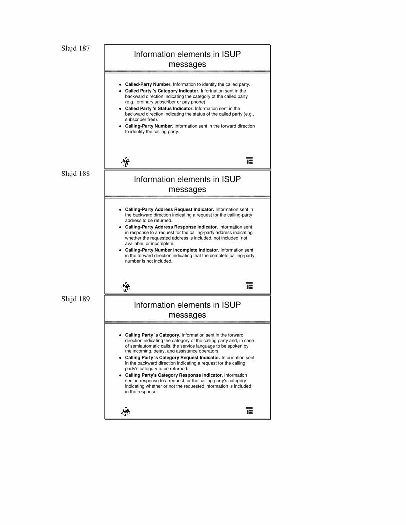
� Called-Party Number. Information to identify the called party.� Called Party 's Category Indicator. Infortnation sent in the
backward direction indicating the category of the called party (e.g., ordinary subscriber or pay phone).
� Called Party 's Status Indicator. Information sent in the backward direction indicating the status of the called party (e.g.,subscriber free).
� Calling-Party Number. Information sent in the forward directionto identify the calling party.
Slajd 188 Information elements in ISUP
messages
� Calling-Party Address Request Indicator. Information sent in the backward direction indicating a request for the calling-partyaddress to be returned.
� Calling-Party Address Response Indicator. Information sent in response to a request for the calling-party address indicating whether the requested address is included, not included, notavailable, or incomplete.
� Calling-Party Number Incomplete Indicator. Information sent in the forward direction indicating that the complete calling-partynumber is not included.
Slajd 189 Information elements in ISUP
messages
� Calling Party 's Category. Information sent in the forward direction indicating the category of the calling party and, in case of semiautomatic calls, the service language to be spoken bythe incoming, delay, and assistance operators.
� Calling Party 's Category Request Indicator. Information sent in the backward direction indicating a request for the calling party's category to be returned.
� Calling Party's Category Response Indicator. Information sent in response to a request for the calling party's category indicating whether or not the requested information is included in the response.
Slajd 190 Information elements in ISUP
messages
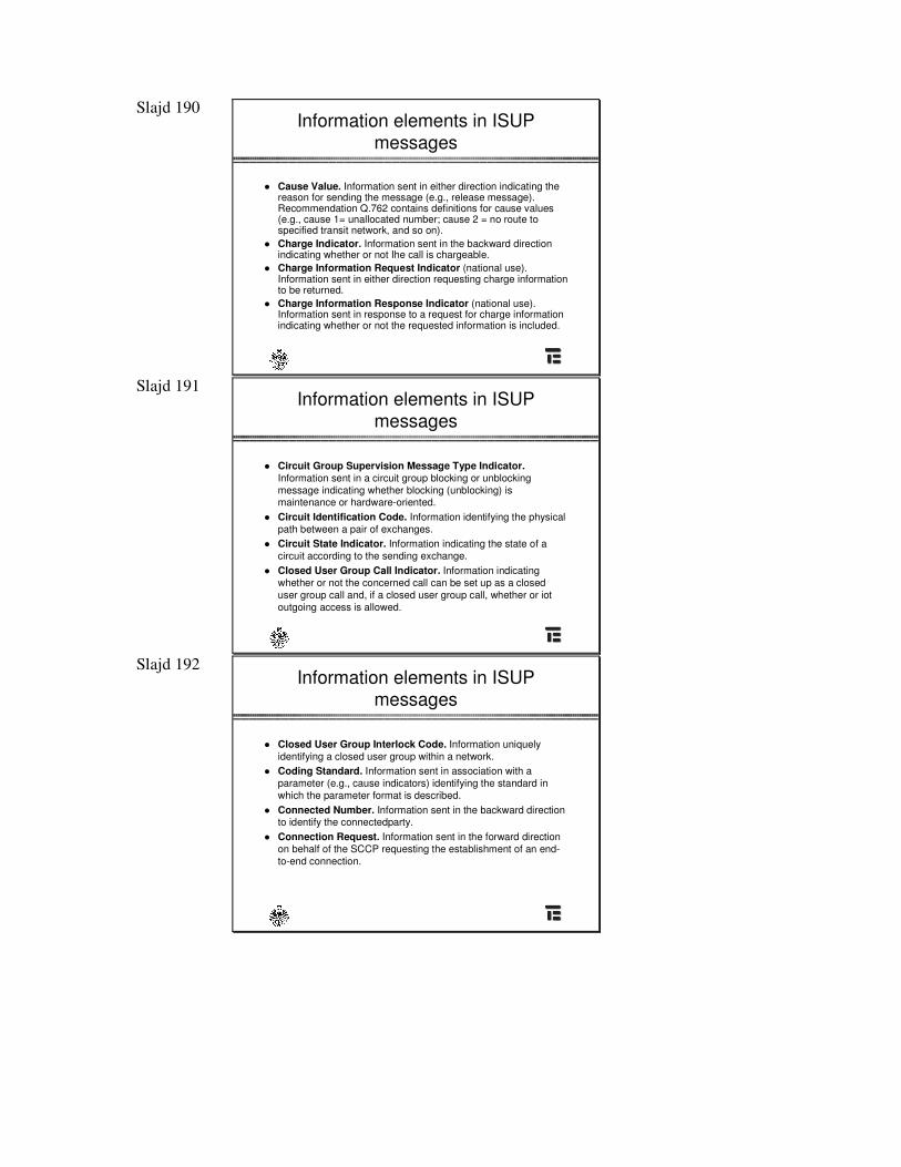
� Cause Value. Information sent in either direction indicating the reason for sending the message (e.g., release message).Recommendation Q.762 contains definitions for cause values(e.g., cause 1= unallocated number; cause 2 = no route tospecified transit network, and so on).
� Charge Indicator. Information sent in the backward direction indicating whether or not Ihe call is chargeable.
� Charge Information Request Indicator (national use).Information sent in either direction requesting charge informationto be returned.
� Charge Information Response Indicator (national use).Information sent in response to a request for charge information indicating whether or not the requested information is included.
Slajd 191 Information elements in ISUP
messages
� Circuit Group Supervision Message Type Indicator.Information sent in a circuit group blocking or unblocking message indicating whether blocking (unblocking) is maintenance or hardware-oriented.
� Circuit Identification Code. Information identifying the physical path between a pair of exchanges.
� Circuit State Indicator. Information indicating the state of acircuit according to the sending exchange.
� Closed User Group Call Indicator. Information indicating whether or not the concerned call can be set up as a closed user group call and, if a closed user group call, whether or iot outgoing access is allowed.
Slajd 192 Information elements in ISUP
messages
� Closed User Group Interlock Code. Information uniquely identifying a closed user group within a network.
� Coding Standard. Information sent in association with aparameter (e.g., cause indicators) identifying the standard in which the parameter format is described.
� Connected Number. Information sent in the backward directionto identify the connectedparty.
� Connection Request. Information sent in the forward directionon behalf of the SCCP requesting the establishment of an end-to-end connection.
Slajd 193 Information elements in ISUP
messages
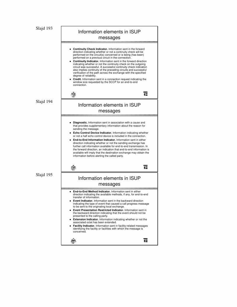
� Continuity Check Indicator. Information sent in the forward direction indicating whether or not a continuity check will beperformed on the circuit(s) concerned or is being (has been)performed on a previous circuit in the connection.
� Continuity Indicator. Information sent in the forward direction indicating whether or not the continuity check on the outgoing circuit was successful. A successful continuity check indication also implies continuity of the preceding circuits and successfulverification of the path across the exchange with the specified degree of reliability.
� Credit. Information sent in a connection request indicating the window size requested by the SCCP for an end-to-end connection.
Slajd 194 Information elements in ISUP
messages
� Diagnostic. Information sent in association with a cause and that provides supplementary information about the reason forsending the message.
� Echo Control Device Indicator. Information indicating whether or not a half echo control device is included in the connection.
� End-to-End Information Indicator. Information sent in either direction indicating whether or not the sending exchange has further call information available for end-to-end transmission. Inthe forward direction, an indication that end-to-end information is available will imply that the destination exchange may obtain the information before alerting the called party.
Slajd 195 Information elements in ISUP
messages� End-to-End Method Indicator. Information sent in either
direction indicating the available methods, if any, for end-to-endtransfer of information.
� Event Indicator. Information sent in the backward direction indicating the type of event that caused a call progress messageto be sent to the originating local exchange.
� Event Presentation Restricted Indicator. Information sent in the backward direction indicating that the event should not bepresented to the calling party.
� Extension Indicator. Information indicating whether or not the associated octet has been extended.
� Facility Indicator. Information sent in facility-related messages identifying the facility or facilities with which the message isconcerned.
Slajd 196 Information elements in ISUP
messages
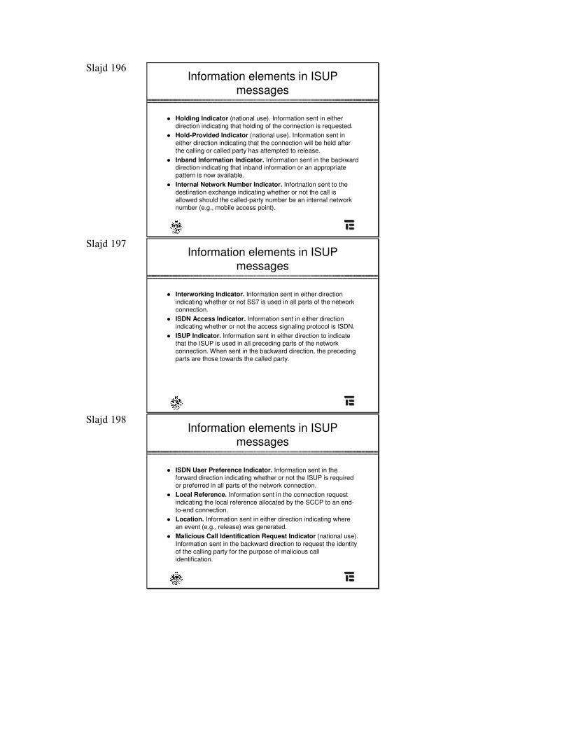
� Holding Indicator (national use). Information sent in either direction indicating that holding of the connection is requested.
� Hold-Provided Indicator (national use). Information sent in either direction indicating that the connection will be held after the calling or called party has attempted to release.
� Inband Information Indicator. Information sent in the backward direction indicating that inband information or an appropriate pattern is now available.
� Internal Network Number Indicator. Infortnation sent to the destination exchange indicating whether or not the call is allowed should the called-party number be an internal network number (e.g., mobile access point).
Slajd 197 Information elements in ISUP
messages
� Interworking Indicator. Information sent in either direction indicating whether or not SS7 is used in all parts of the network connection.
� ISDN Access Indicator. Information sent in either direction indicating whether or not the access signaling protocol is ISDN.
� ISUP Indicator. Information sent in either direction to indicate that the ISUP is used in all preceding parts of the network connection. When sent in the backward direction, the preceding parts are those towards the called party.
Slajd 198 Information elements in ISUP
messages
� ISDN User Preference Indicator. Information sent in the forward direction indicating whether or not the ISUP is required or preferred in all parts of the network connection.
� Local Reference. Information sent in the connection request indicating the local reference allocated by the SCCP to an end-to-end connection.
� Location. Information sent in either direction indicating where an event (e.g., release) was generated.
� Malicious Call Identification Request Indicator (national use).Information sent in the backward direction to request the identity of the calling party for the purpose of malicious call identification.
Slajd 199 Information elements in ISUP
messages
� Modifcation Indicator. Information sent in the call modification indicators parameter indicating whether the call modification isto service 1 or service 2.
� National/International Call Indicator. Information sent in the forward direction indicating to the destination national network whether the call has to be treated as an internationalcall or asnational call.
� Nature of Address Indicator. Information sent in association with an address indicating the nature of that address (e.g., ISDNinternational number, ISDN national significant number, or ISDNsubscriber number).
Slajd 200 Information elements in ISUP
messages
� Numbering Plan Indicator. Information sent in association witha number indicating the numbering plan used for that number(e.g., ISDN number, telex number).
� Odd/Even Indicator. Information sent in association with an address indicating whether the number of address signals contained in the address is even or odd.
� Original Called Number. Information sent in the forward direction when a call is redirected and identifies the original called party.
� Original Redirection Reason. Information sent in either direction indicating the reason why the call was originally redirected.
Slajd 201 Information elements in ISUP
messages
� Point Code. Information sent in the call reference parameter indicating the code of the signaling point in which the call identity allocated to the call reference is relevant.
� Protocol Class. Information sent in the connection request parameter indicating the protocol class requested by the SCCP for the end-to-end connection.
� Protocol Control Indicator. Information consisting of the end-to-end method indicator, the interworking indicator, the end-to-end information indicator, the SCCP method, and the ISUPindicator. The protocol control indicator is contained in both the forward and backward call indicators parameter field and describes the signaling capabilities within the network connection.
Slajd 202 Information elements in ISUP
messages
� Range. Information sent in a circuit group supervision message(e.g., circuit group blocking) to indicate the range of circuits affected by the action in the message.
� Recommendation Indicator. Information sent in association with a cause value identifying the recommendation to which the cause value applies.
� Redirecting Indicator. Information sent in either direction indicating whether the call has been forwarded or rerouted and whether or not presentation of redirection information to the calling party is restricted.
Slajd 203 Information elements in ISUP
messages
� Redirecting Number. Information sent in the forward direction when a call is redirected more than once, indicating the number from which the call was last redirected.
� Redirecting Reason. Information sent in either direction indicating, in the case of calls undergoing multiple redirections,the reason why the call has been redirected.
� Redirection Counter. Information sent in either direction indicating the number of redirections that have occurred on acall.
� Redirection Number. Information sent in the backward direction indicating the number towards which the call must bererouted or has been forwarded.
Slajd 204 Information elements in ISUP
messages
� Routing Label. Information provided to the MTP for the purpose of message routing.
� Satellite Indicator. Information sent in the forward direction indicating the number of satellite circuits in the connection.
� SCCP Method Indicator. Information sent in either direction indicating the available SCCP methods, if any, for end-to-endtransfer of information.
� Screening Indicator. Information sent in either direction toindicate whether the address was provided by the user or network.
� Signaling Point Code (national use). Information sent in release message to identify the signaling point in which the call failed.
Slajd 205 Information elements in ISUP
messages
� Solicited Information Indicator. Information sent in an information message to indicate whether or not the message isa response to an information request message.
� Status. Information sent in a circuit group message (e.g., circuit group blocking) to indicate the specific circuits, within the range of circuits stated in the message, that are affected by the action specified in the message.
� Suspended Resume Indicator. Information sent in the suspend and resume messages to indicate suspend/resume was initiated by an ISDN subscriber or by the network.
Slajd 206 Information elements in ISUP
messages
� Temporary Trunk Blocking After Release (national use).Information sent to the exchange at the other end of a circuit(trunk) to indicate low level of congestion at the sending exchange and that the circuit (trunk) should not be reoccupiedby the receiving exchange for a short period of time after release.
� Transit Network Selection (national use). Information serlt in the initial address message indicating the transit network(s)requested to be used in the call.
� Transmission Medium Requirement. Information sent in the forward direction indicating the type of transmission mediumrequired for the connection (e.g., 64-kbps unrestrictedtransmission, speech).
Slajd 207 Information elements in ISUP
messages
� User Service Information. Information sent in the forward direction indicating the bearer capability requested by the callingparty.
� User-to-User Indicators. Information sent in association with arequest (or response to a request) for user-to-user signaling supplementary service(s).
� User-to-User Information. Information generated by a user and transferred transparently through the interexchange network between the originating and terminating local exchanges.
Slajd 208
Transactions Capabilities (TC)
Slajd 209
Transaction Capabilities
� Interactive applications in a distributed environment
� Interface between application and network layer service
� TC applications
Slajd 210
Transaction Capabilities (TC)
� TC is a set of protocols and functions used bydistributed applications located in the network and communicating with each other
� TC refers to the application layer protocols, i.e.incorporates some features of transport, session and presentation layers
� TCAP (Transaction Capabilities Application Part)provides set of tools in connectionless network tomanage distributed applications
� TCAP uses directly services of SCCP
Slajd 211
Application layer structure
Application Service ElementASE
Component Sublayer
Transaction Sublayer
TCAP
TC-Primitives
TR-Primitives
to/from Application
ApplicationLayer
SCCP-Primitives
„vertical” communication
Slajd 212
TCAP sublayer messages
InvokeReturn ResultReturn ErrorReject
BeginContinueEndAbortUnidirectional
CSL CSL
TSL TSL
CSL = Component SublayerTSL = Transaction Sublayer
„horizontal” communication
Slajd 213
TC Sublayers
� The Transaction Sublayer:» defines the context within which a
complete remote operation between TCusers is executed
� The Component Sublayer:» allows several dialogues to be run
concurrently between TC users (manages sending and receiving of requests and responses)
Slajd 214
The Transaction Sublayer
� Manages transactions (or dialogues)� Two types of dialogue:
» unstructured dialogue: Transaction Sublayer provides ameans to send to remote peer one or more components thatdo not require any response
» structured dialogue: this is sequence of TC- and TR-primitives with unique dialogue IDs. TC-BEGIN, TC-CONTINUE, TC-END, TC-U-ABORT, TC-U-ABORT, TC-P-ABORT and appropriate TR-* primitives
Slajd 215
The Component Sublayer
� Component is an element included in the TCmessages; it consists of either a request to perform or a reply
� Few components obtained from TC user can betransmitted in a single message
� Successive components exchanged between twoTC-users when executing an application constitute adialogue
� CSL allows several dialogues to be run concurrently between TC-users
Slajd 216
The Component Sublayer
� The Component Sublayer uses four classes of remote operations:
� Class 1: both success and failure in performing the remote operation is reported
� Class 2: only failure is reported� Class 3: only success is reported� Class 4: neither success nor failure is reported
Slajd 217
TCAP sublayer messages
Invoke
Begin
Components
Invoke
...
Slajd 218
Example of using TCAP
BEGIN {Invoke with ID#1[Provide Routing Number (Dialed 800-Number)]}
CONTINUE {Invoke with ID#2 [Play Ann. & Collect Digits];Linked to Invoke with ID#1}
CONTINUE {RR (Collected Digits); Related to Invoke with ID#2}
END {RR (Routing Number); Releted to Invoke with ID#1}
Originating Exchange Network Database
Slajd 219
Rola SS7 w realizacji sieci inteligentnej (IN - Intelligent
Network)
Slajd 220
Plan
� Koncepcja sieci inteligentnej IN� Ogólna architektura IN� Rola SS7 w IN� Usługi, funkcje i akcje� Aspekty komunikacji dla usług
zaawansowanych
Slajd 221
Definicja sieci inteligentnej
� Poj�cie "sie� inteligentna" oznacza: koncepcj� i architektur� sieci zapewniaj�cej uniwersalne styki pomi�dzy elementami sieci realizuj�cymi usługi a systemami komutacyjnymi i transmisyjnymi, przy czym w sieci działa wielu operatorów i jest eksploatowany sprz�t pochodz�cy od wielu producentów.
� Koncepcja IN pojawiła si� koło 1980 roku (nale�y mie� na wzgl�dzie ówczesny stan telekomunikacji i informatyki)
� Usługi inteligentne, pierwotnie realizowane w odr�bnej architekturze, s� obecnie wbudowane w (B)ISUP
Slajd 222 Warunki konieczne dla realizacji sieci
inteligentnej
� wprowadzenie central o sterowaniu programowym,� realizacja sygnalizacji wydzielonej, czyli w kanale
wspólnym (SS7),� cyfryzacja komutacji i transmisji,� rozwój techniki komputerowej i in�ynierii
oprogramowania - wprowadzenie rozproszonych baz danych.
Wszystkie te warunki zostały spełnione dopiero około 1980 roku
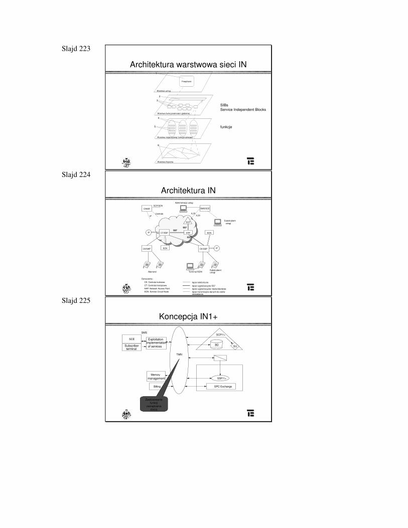
Slajd 223
Architektura warstwowa sieci IN1
3
4
5
6
2
Warstwa us³ug
Warstwa funkcjonalnoœci globalnej
Warstwa rozproszonej funkcjonalnoœci
Warstwa fizyczna
Freephone
SIBs Service Independent Blocks
funkcje
Slajd 224
Architektura IN
�OA&M SMS/SCE
CT/SSP
CK/NAP
SCP �IP STP SCN
SCN CK/SSP IP
�
Administracja usług
X.25X.25
Subskrybentusługi
SCP/SCN
CentraleIP
SS7
Abonenci Terminal ISDNSubskrybentusługi
Oznaczenia:
CK: Centrala ko�cowa
CT: Centrala tranzytowaNAP: Network Access PointSCN: Service Circuit Node
ł�cze telefoniczne
ł�cze sygnalizacyjne SS7ł�cze sygnalizacyjne niestandardoweł�cze transmisyjne danych do celów zarz�dzania
SS7
SS7
Slajd 225
Koncepcja IN1+
Memory
pamiêci¹
Billing
SCE
SMS
TMN
SSP/1+
SPC Exchange
SUBD
SCP/1+
Subscriberterminal
management
Exploitationimplementationof services
Zastosowanie funkcji
zarz�dzania sieci�
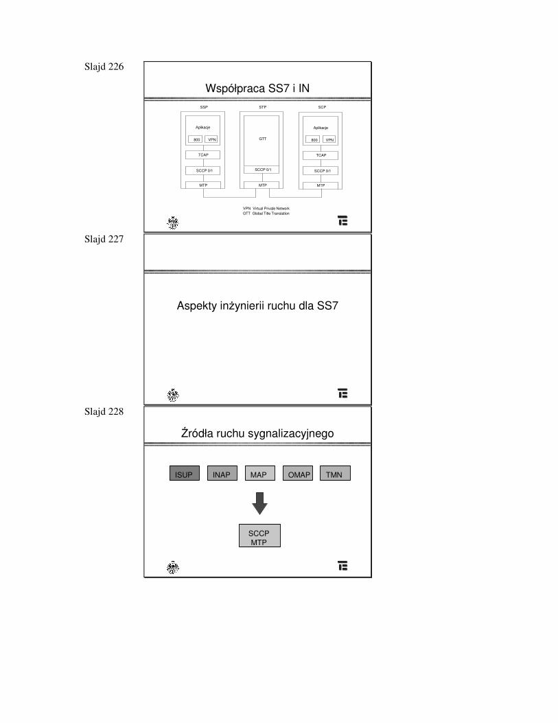
Slajd 226
Współpraca SS7 i IN
Aplikacje
800 VPN
TCAP
SCCP 0/1
MTP
GTT
SCCP 0/1
MTP
Aplikacje
800 VPN
TCAP
SCCP 0/1
MTP
SSP STP SCP
VPN Virtual Private Network GTT Global Title Translation
Slajd 227
Aspekty in�ynierii ruchu dla SS7
Slajd 228
�ródła ruchu sygnalizacyjnego
ISUP INAP MAP OMAP TMN
SCCPMTP
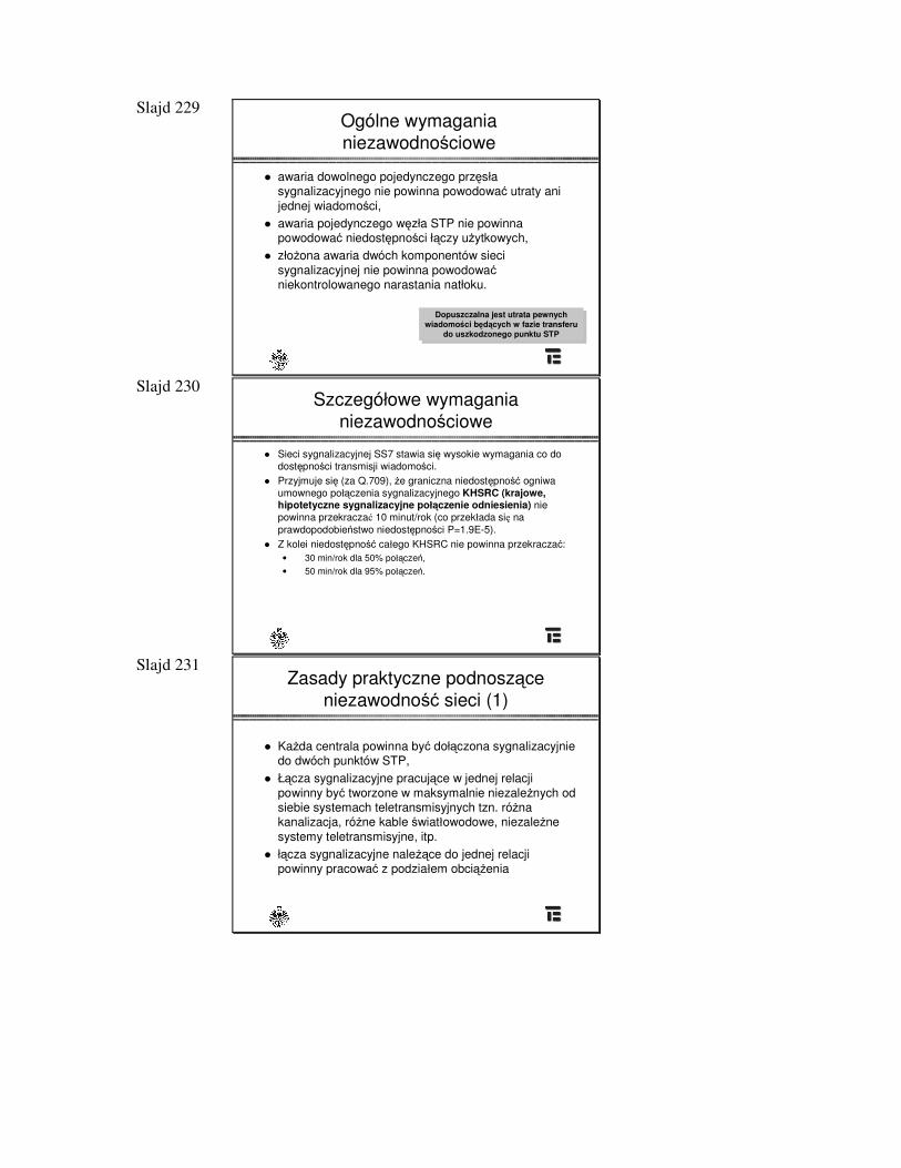
Slajd 229 Ogólne wymagania niezawodno�ciowe
� awaria dowolnego pojedynczego prz�sła sygnalizacyjnego nie powinna powodowa� utraty ani jednej wiadomo�ci,
� awaria pojedynczego w�zła STP nie powinna powodowa� niedost�pno�ci ł�czy u�ytkowych,
� zło�ona awaria dwóch komponentów sieci sygnalizacyjnej nie powinna powodowa� niekontrolowanego narastania natłoku.
Dopuszczalna jest utrata pewnych wiadomo�ci b�d�cych w fazie transferu
do uszkodzonego punktu STP
Slajd 230 Szczegółowe wymagania
niezawodno�ciowe
� Sieci sygnalizacyjnej SS7 stawia si� wysokie wymagania co do dost�pno�ci transmisji wiadomo�ci.
� Przyjmuje si� (za Q.709), �e graniczna niedost�pno�� ogniwa umownego poł�czenia sygnalizacyjnego KHSRC (krajowe, hipotetyczne sygnalizacyjne poł�czenie odniesienia) nie powinna przekracza� 10 minut/rok (co przekłada si� na prawdopodobie�stwo niedost�pno�ci P=1.9E-5).
� Z kolei niedost�pno�� całego KHSRC nie powinna przekracza�:• 30 min/rok dla 50% poł�cze�,• 50 min/rok dla 95% poł�cze�.
Slajd 231 Zasady praktyczne podnosz�ce
niezawodno�� sieci (1)
� Ka�da centrala powinna by� doł�czona sygnalizacyjnie do dwóch punktów STP,
� Ł�cza sygnalizacyjne pracuj�ce w jednej relacji powinny by� tworzone w maksymalnie niezale�nych od siebie systemach teletransmisyjnych tzn. ró�na kanalizacja, ró�ne kable �wiatłowodowe, niezale�ne systemy teletransmisyjne, itp.
� ł�cza sygnalizacyjne nale��ce do jednej relacji powinny pracowa� z podziałem obci��enia
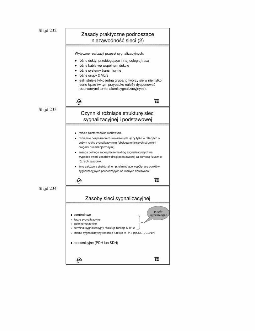
Slajd 232 Zasady praktyczne podnosz�ce
niezawodno�� sieci (2)
Wytyczne realizacji prz�seł sygnalizacyjnych:
� ró�ne dukty, przebiegaj�ce inn�, odległ� tras�� ró�ne kable we wspólnym dukcie� ró�ne systemy transmisyjne� ró�ne grupy 2 Mb/s� je�li istnieje tylko jedna grupa to tworzy si� w niej tylko
jedno ł�cze (w tym przypadku nale�y dysponowa� rezerwowymi terminalami sygnalizacyjnymi).
Slajd 233 Czynniki ró�ni�ce struktur� sieci sygnalizacyjnej i podstawowej
� relacje zainteresowa� ruchowych,
� tworzenie bezpo�rednich skojarzonych ł�czy tylko w relacjach o
du�ym ruchu sygnalizacyjnym (obsługa mniejszych strumieni
drogami quasiskojarzonymi),
� zasada pełnego zabezpieczenia dróg sygnalizacyjnych na
wypadek awarii zasobów drogi podstawowej za pomoc� fizycznie
ró�nych zasobów,
� inne zało�enia strukturalne np. eliminuj�ce współprac� punktów
sygnalizacyjnych pochodz�cych od ró�nych dostawców.
Slajd 234
Zasoby sieci sygnalizacyjnej
� centralowe � ł�cze sygnalizacyjne � pole komutacyjne � terminal sygnalizacyjny realizuje funkcje MTP-2
� moduł sygnalizacyjny realizuje funkcje MTP 3 (np.SILT, CCNP)
� transmisyjne (PDH lub SDH)
prz�słosygnalizacyjne
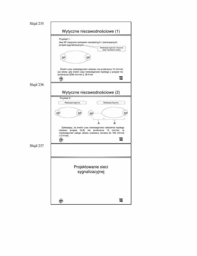
Slajd 235
Wytyczne niezawodno�ciowe (1)
SPSP
Przykład 1:dwa SP zwi�zane zestawem niezale�nych i równowa�nych prz�seł sygnalizacyjnych
�redni czas niedost�pno�ci zestawu nie przekracza 10 min/rokju� wtedy, gdy �redni czas niedost�pno�ci ka�dego z prz�seł nie przekracza 2292 min/rok tj. 38 h/rok
Realizacja logiczna i fizyczna (dwa niezale�ne dukty)
Slajd 236
Wytyczne niezawodno�ciowe (2)
SPSP
Przykład 2:
Zakładaj�c, �e �redni czas niedost�pno�ci oddzielnie ka�degozestawu prz�seł (A,B) nie przekracza 10 min/rok, to niedost�pno�� całego układu (zestawu) wzrasta do 769 min/rok (13 h/rok).
Realizacja logiczna
SPSP
Realizacja fizyczna
A B
Slajd 237
Projektowanie siecisygnalizacyjnej

Slajd 238
Zasoby sieci sygnalizacyjnej
Etapy post�powania przy metodzie analitycznej szacowania ruchu sygnalizacyjnego:
� ustali� wersj� zaimplementowanego systemu sygnalizacji� przyj�� czasy trwania przeci�tnego poł�czenia skutecznego i
nieskutecznego oraz procentowy udział tych poł�cze�� przyj�� zało�enia przeci�tnego protokołu (np. liczba cyfr
przekazywanych en-block i na zakładk�)� przyj�� zało�enie o usługach dodatkowych� obliczy� ł�czn� długo�� wiadomo�ci � przyj�� zało�enia o symetrii ruchu
Slajd 239 Obliczenie liczby ł�czy rozmównych
obsługiwanych przez ł�cze sygnalizacyjne
qmax * P
e * L * (X/T + Xn/Tn)N =
� N - liczba ł�czy rozmównych � P - maksymalna przepływno�� ł�cza sygnalizacyjnego (8000 okt/s) � qmax - maks. wykorzystanie ł�cza sygnalizacyjnego (0.2) � e - ruch na ł�czu rozmównym w GNR (0.7 Erl)� L - liczba oktetów sygnalizacyjnych potrzebnych �rednio do obsługi 1
ł�cza (163)� X - frakcja wywoła� efektywnych (np. 0.4)� Xn - frakcja wywoła� nieskutecznych (np. 0.3) � T - �redni czas trwania poł�czenia (90 s)� Tn - czas zaj�to�ci ł�cza w obsłudze wywoła� nieskutecznych (15 s)
Slajd 240 Zało�enia wymiarowania łacza
sygnalizacyjnego
� Podstawowym parametrem jest obci��enie prz�sła sygnalizacyjnego
� • długo�� bitowa jednostki wiadomo�ci (dm) - 120 � • �rednia długo�� (czas) jednostki wiadomo�ci (tm) -1,875 ms� • �rednia długo�� rozmowy 180s� • �rednia liczba jednostek wiadomo�ci / rozmow� 6� jednostka wiadomo�ci (przyj�to przeci�tn� długo��SIF równ� 64):dm= 8 + 8 + 8 + 8 + 8 + 64 + 16 = 120
F FSN+FIB BSN+BIB LI SIO SIF CB� co przekłada si� na czas: tm= dm / 64000 = 1,875 ms
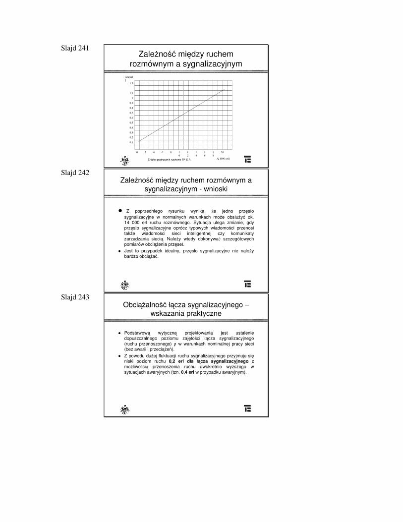
Slajd 241 Zale�no�� mi�dzy ruchem
rozmównym a sygnalizacyjnymAm[erl]
1,3
1,1
1
0,9
0,8
0,7
0,6
0,5
0,4
0,3
0,2
0,1
0 2 4 6 8 10
12
14
16
18
20
A[1000 erl]�ródło: podr�cznik ruchowy TP S.A.
Slajd 242 Zale�no�� mi�dzy ruchem rozmównym a
sygnalizacyjnym - wnioski
� Z poprzedniego rysunku wynika, �e jedno prz�sło sygnalizacyjne w normalnych warunkach mo�e obsłu�y� ok. 14 000 erl ruchu rozmównego. Sytuacja ulega zmianie, gdy prz�sło sygnalizacyjne oprócz typowych wiadomo�ci przenosi tak�e wiadomo�ci sieci inteligentnej czy komunikaty zarz�dzania sieci�. Nale�y wtedy dokonywa� szczegółowych pomiarów obci��enia prz�seł.
� Jest to przypadek idealny, prz�sło sygnalizacyjne nie nale�y bardzo obci��a�.
Slajd 243 Obci��alno�� ł�cza sygnalizacyjnego –
wskazania praktyczne
� Podstawow� wytyczn� projektowania jest ustalenie dopuszczalnego poziomu zaj�to�ci ł�cza sygnalizacyjnego (ruchu przenoszonego) ρ w warunkach nominalnej pracy sieci (bez awarii i przeci��e�).
� Z powodu du�ej fluktuacji ruchu sygnalizacyjnego przyjmuje si�niski poziom ruchu 0,2 erl dla ł�cza sygnalizacyjnego z mo�liwo�ci� przenoszenia ruchu dwukrotnie wy�szego w sytuacjach awaryjnych (tzn. 0,4 erl w przypadku awaryjnym).
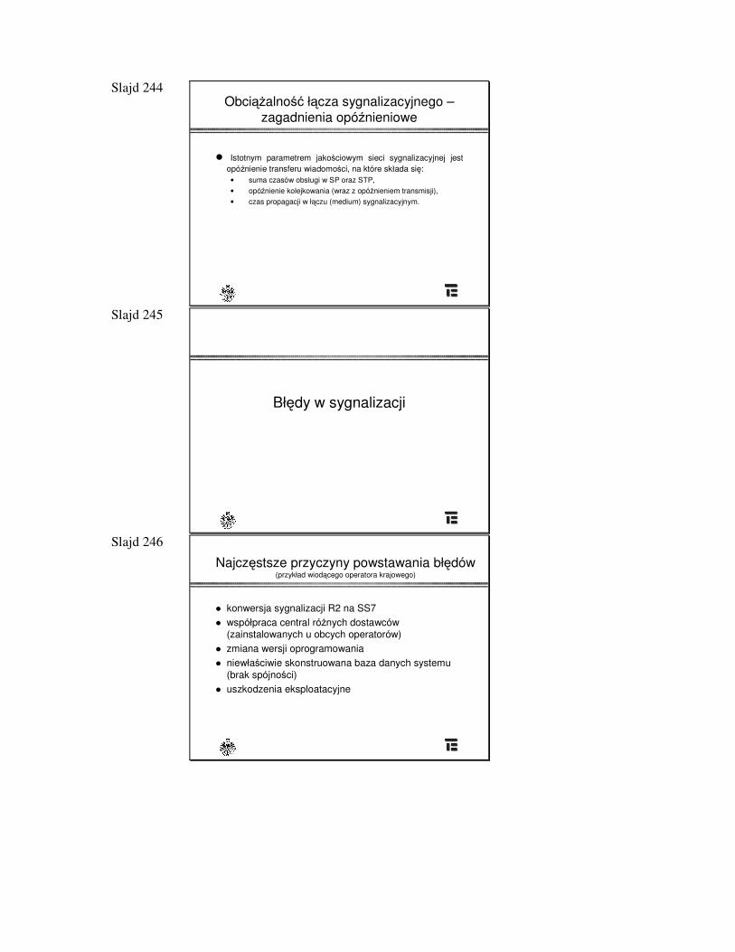
Slajd 244 Obci��alno�� ł�cza sygnalizacyjnego –
zagadnienia opónieniowe
� Istotnym parametrem jako�ciowym sieci sygnalizacyjnej jest opónienie transferu wiadomo�ci, na które składa si�:
• suma czasów obsługi w SP oraz STP,• opónienie kolejkowania (wraz z opónieniem transmisji),• czas propagacji w ł�czu (medium) sygnalizacyjnym.
Slajd 245
Bł�dy w sygnalizacji
Slajd 246
Najcz�stsze przyczyny powstawania bł�dów (przykład wiod�cego operatora krajowego)
� konwersja sygnalizacji R2 na SS7� współpraca central ró�nych dostawców
(zainstalowanych u obcych operatorów)� zmiana wersji oprogramowania� niewła�ciwie skonstruowana baza danych systemu
(brak spójno�ci)� uszkodzenia eksploatacyjne
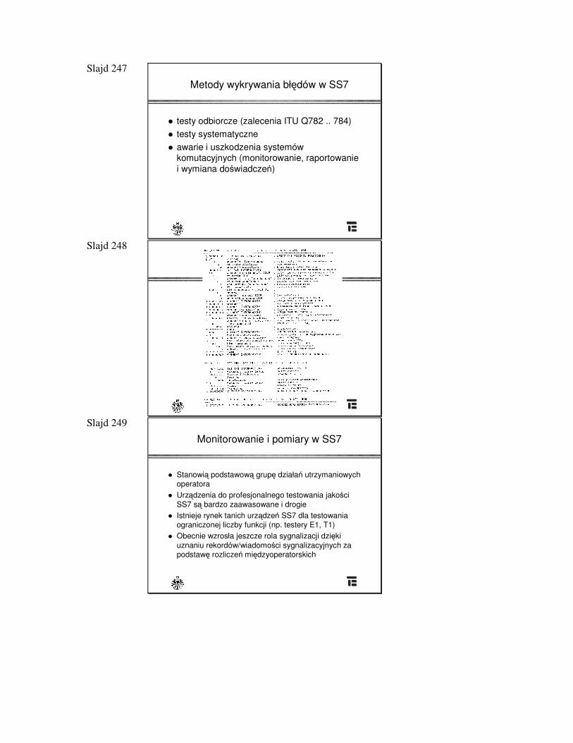
Slajd 247
Metody wykrywania bł�dów w SS7
� testy odbiorcze (zalecenia ITU Q782 .. 784)� testy systematyczne� awarie i uszkodzenia systemów
komutacyjnych (monitorowanie, raportowanie i wymiana do�wiadcze�)
Slajd 248
Przykład (listing z urz�dzenia pomiarowego)
Slajd 249
Monitorowanie i pomiary w SS7
� Stanowi� podstawow� grup� działa� utrzymaniowychoperatora
� Urz�dzenia do profesjonalnego testowania jako�ci SS7 s� bardzo zaawasowane i drogie
� Istnieje rynek tanich urz�dze� SS7 dla testowania ograniczonej liczby funkcji (np. testery E1, T1)
� Obecnie wzrosła jeszcze rola sygnalizacji dzi�ki uznaniu rekordów/wiadomo�ci sygnalizacyjnych za podstaw� rozlicze� mi�dzyoperatorskich
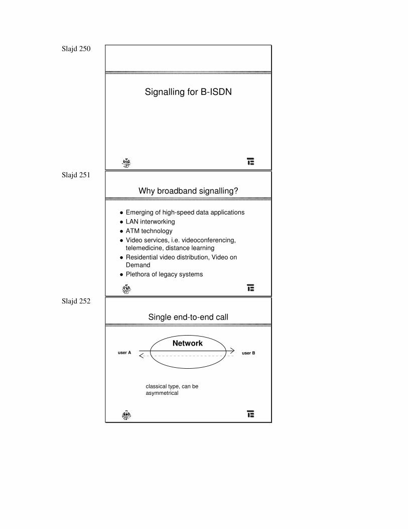
Slajd 250
Signalling for B-ISDN
Slajd 251
Why broadband signalling?
� Emerging of high-speed data applications� LAN interworking� ATM technology� Video services, i.e. videoconferencing,
telemedicine, distance learning� Residential video distribution, Video on
Demand� Plethora of legacy systems
Slajd 252
Single end-to-end call
Networkuser A user B
classical type, can be asymmetrical
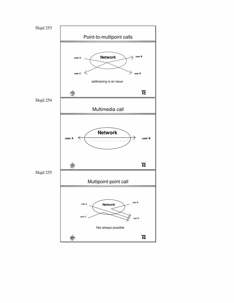
Slajd 253
Point-to-mutlipoint calls
Networkuser A user B
user C user D
addressing is an issue
Slajd 254
Multimedia call
Networkuser A user B
Slajd 255
Multipoint-point call
user A
user C
user B
user D
Network
Not always possible
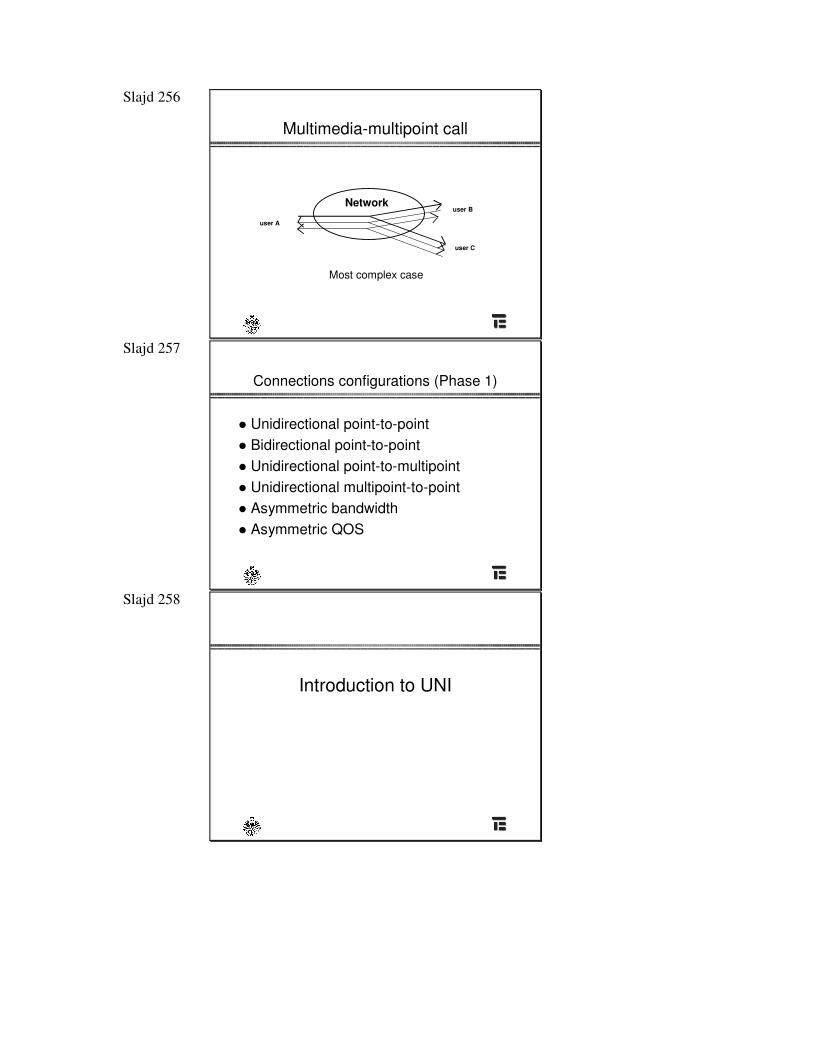
Slajd 256
Multimedia-multipoint call
user A
user B
user C
Network
Most complex case
Slajd 257
Connections configurations (Phase 1)
� Unidirectional point-to-point� Bidirectional point-to-point� Unidirectional point-to-multipoint� Unidirectional multipoint-to-point� Asymmetric bandwidth� Asymmetric QOS
Slajd 258
Introduction to UNI
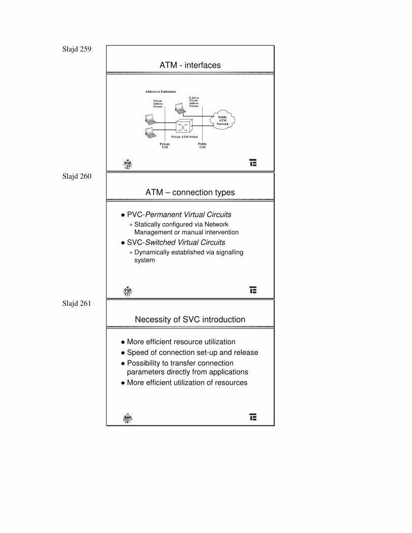
Slajd 259
ATM - interfaces
Address to Endstation
PrivateAddressFormat
PrivateAddressFormat
E.164 or
Private ATM Switch
PrivateUNI
PublicUNI
PublicATM
Network
Slajd 260
ATM – connection types
� PVC-Permanent Virtual Circuits» Statically configured via Network
Management or manual intervention
� SVC-Switched Virtual Circuits» Dynamically established via signalling
system
Slajd 261
Necessity of SVC introduction
� More efficient resource utilization� Speed of connection set-up and release� Possibility to transfer connection
parameters directly from applications� More efficient utilization of resources
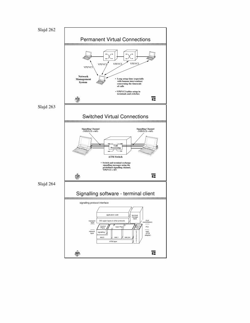
Slajd 262
Permanent Virtual Connections
NetworkManagement
System
VPI/VCIVPI/VCI VPI/VCI VPI/VCI
• Long setup time (especiallywith human intervention)
• VPI/VCI tables setup interminals and switches
concerning the timescaleof calls
Slajd 263
Switched Virtual Connections
ATM Switch
• Switch and terminal exchangesignalling messages using thepredefined signalling channel, VPI/VCI = 0/5
CallProcessing
Signalling Channel(VPI/VCI = 0/5)
Signalling Channel(VPI/VCI = 0/5)
Slajd 264
Signalling software - terminal client
User Plane Admin.Plane
signalling
AAL5 AAL1 AAL3/4
ATM layer
ControlPlane
terminalmanage-
ment
application code
OSI upper layers & other protocolstransportlayer
networklayer
PUF(workstation)
PCI
NAF(ATM
adapter)
management
signalling protocol interface
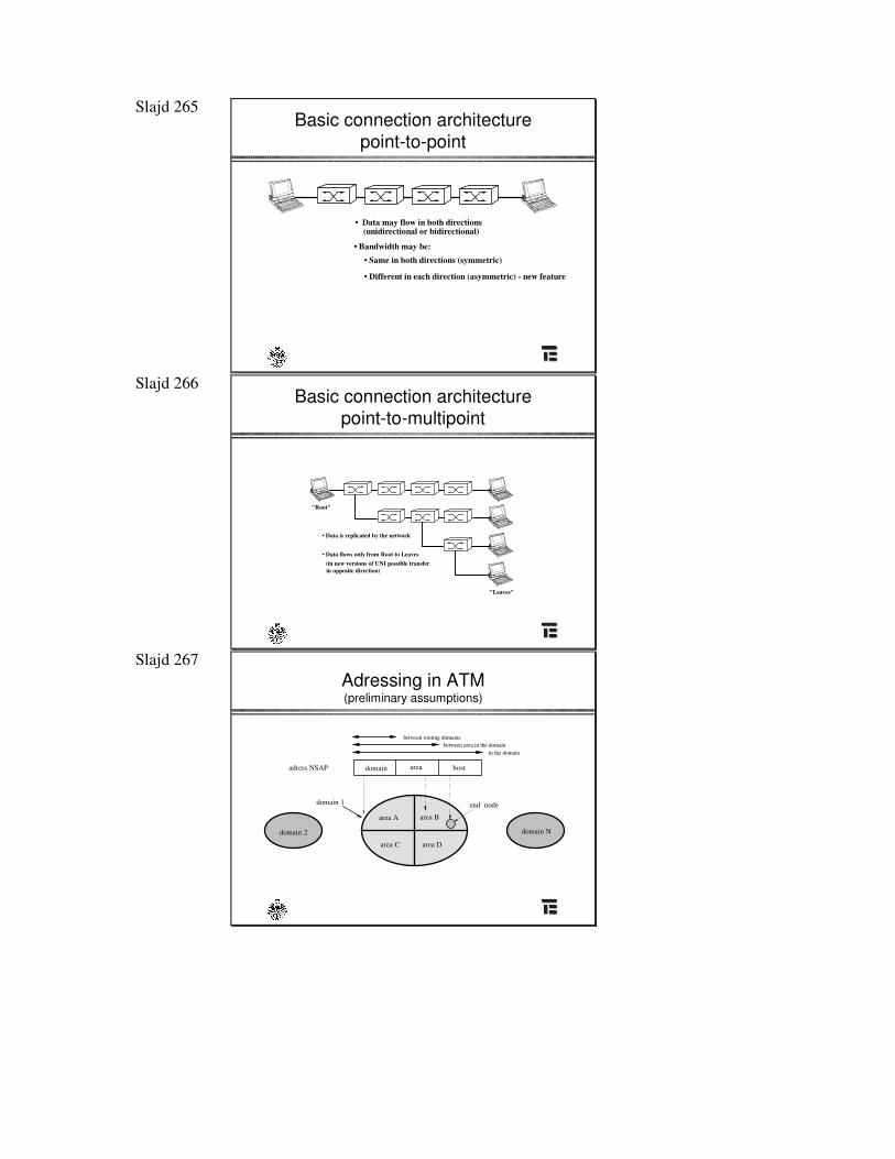
Slajd 265 Basic connection architecture
point-to-point
• Data may flow in both directions(unidirectional or bidirectional)
• Bandwidth may be:• Same in both directions (symmetric)
• Different in each direction (asymmetric) - new feature
Slajd 266 Basic connection architecture
point-to-multipoint
• Data is replicated by the network
• Data flows only from Root to Leaves
"Root"
"Leaves"
(in new versions of UNI possible transferin opposite direction)
Slajd 267 Adressing in ATM(preliminary assumptions)
area A area B
area C area D
end nodedomain 1
domain Ndomain 2
domain area hostadress NSAP
between routing domainsbetween area in the domain
in the domain
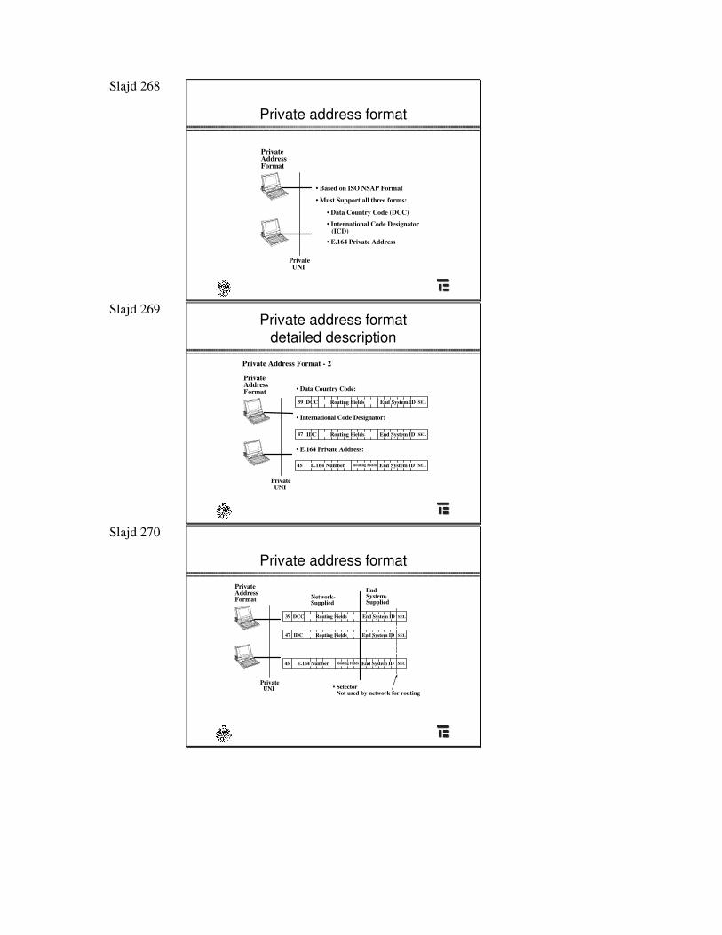
Slajd 268
Private address format
• Based on ISO NSAP Format
PrivateAddressFormat
PrivateUNI
• Must Support all three forms:
• Data Country Code (DCC)
• International Code Designator(ICD)
• E.164 Private Address
Slajd 269 Private address format
detailed description
DCC
Private Address Format - 2
• Data Country Code:PrivateAddressFormat
PrivateUNI
• International Code Designator:
39 Routing Fields End System ID SEL
• E.164 Private Address:
47 IDC Routing Fields End System ID SEL
45 E.164 Number Routing Fields End System ID SEL
Slajd 270
Private address format
DCC
Network-
PrivateAddressFormat
PrivateUNI
39 Routing Fields End System ID SEL
47 IDC Routing Fields End System ID SEL
45 E.164 Number Routing Fields End System ID SEL
Supplied
• Selector Not used by network for routing
System-Supplied
End
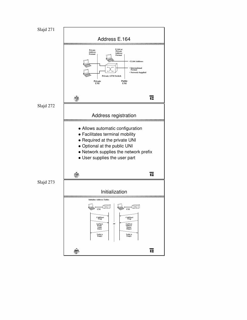
Slajd 271
Address E.164
PrivateAddressFormat
PrivateAddressFormat
E.164 or
Private ATM Switch
PrivateUNI
PublicUNI
• E.164 Address:
• InternationalFormat
• Network-Supplied
Slajd 272
Address registration
� Allows automatic configuration� Facilitates terminal mobility� Required at the private UNI� Optional at the public UNI� Network supplies the network prefix� User supplies the user part
Slajd 273
InitializationInitialize Address Tables
UNI UNI
ColdStartTrap
GetNextPrefixTableEntry
Table isEmpty
ColdStartTrap
GetNextAddressStatusObject
Table isEmpty
or
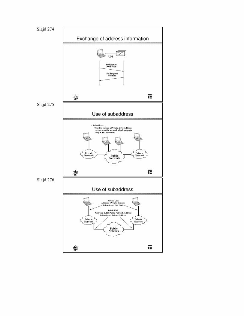
Slajd 274
Exchange of address information
UNI
SetRequestNetPrefix
SetRequestAddress
Slajd 275
Use of subaddress
PublicNetwork
PrivateNetwork
PrivateNetwork
• Subaddress:• Used to convey a Private ATM Address
across a public network which supportsonly E.164 addresses
Slajd 276
Use of subaddress
PublicNetwork
PrivateNetwork
PrivateNetwork
Private UNIAddress: Private Address
Subaddress: Not Used
Public UNIAddress: E.164 Public Network Address
Subaddress: Private Address
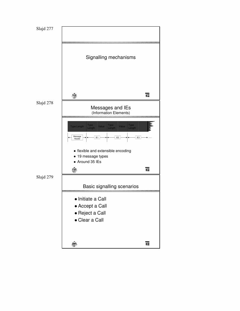
Slajd 277
Signalling mechanisms
Slajd 278 Messages and IEs (Information Elements)
� flexible and extensible encoding� 19 message types� Around 35 IEs
Type Length TypeLength
Value TypeLength
Value TypeLength
….Message Header
Message Header
IE1 IE2 IE3
Slajd 279
Basic signalling scenarios
� Initiate a Call� Accept a Call� Reject a Call� Clear a Call
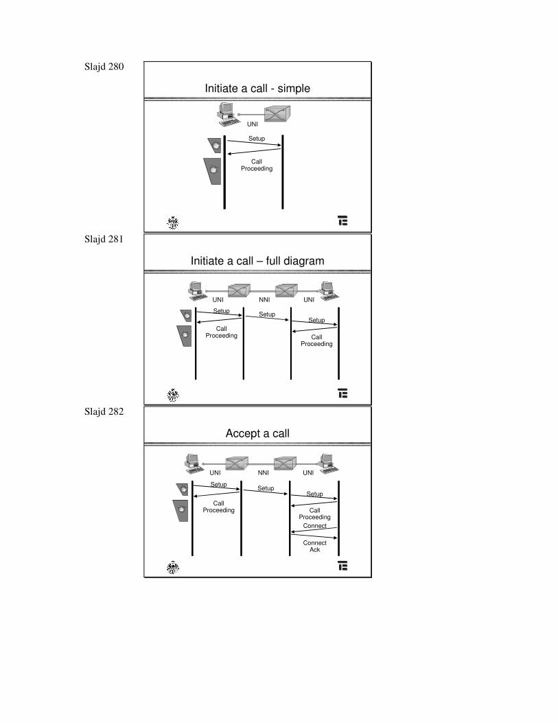
Slajd 280
Initiate a call - simple
CallProceeding
Setup
UNI
912
63
912
63
Slajd 281
Initiate a call – full diagram
CallProceeding
Setup
UNI NNI
CallProceeding
Setup
UNI
Setup912
63
912
63
Slajd 282
Accept a call
CallProceeding
Setup
UNI NNI UNI
CallProceeding
Setup
Connect
Connect Ack
Setup912
63
912
63
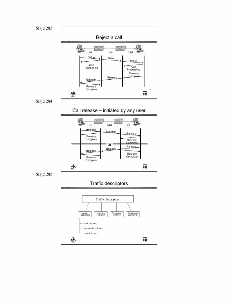
Slajd 283
Reject a call
CallProceeding
Setup
UNI NNI UNI
ReleaseComplete
CallProceeding
Setup
Release
Release Complete
Setup
Release
A
Slajd 284
Call release – initiated by any user
UNI NNI UNI
Release
Release Complete
Release
Release Complete
Release
Release Complete
Release
Release Complete
or
Release
Release
Slajd 285
Traffic descriptors
Source descriptors
Cell delay Tolerance
Compliance definition parameters
Experimental
Traffic descriptors
peak cell rate
sustainable cell rate
burst tolerance
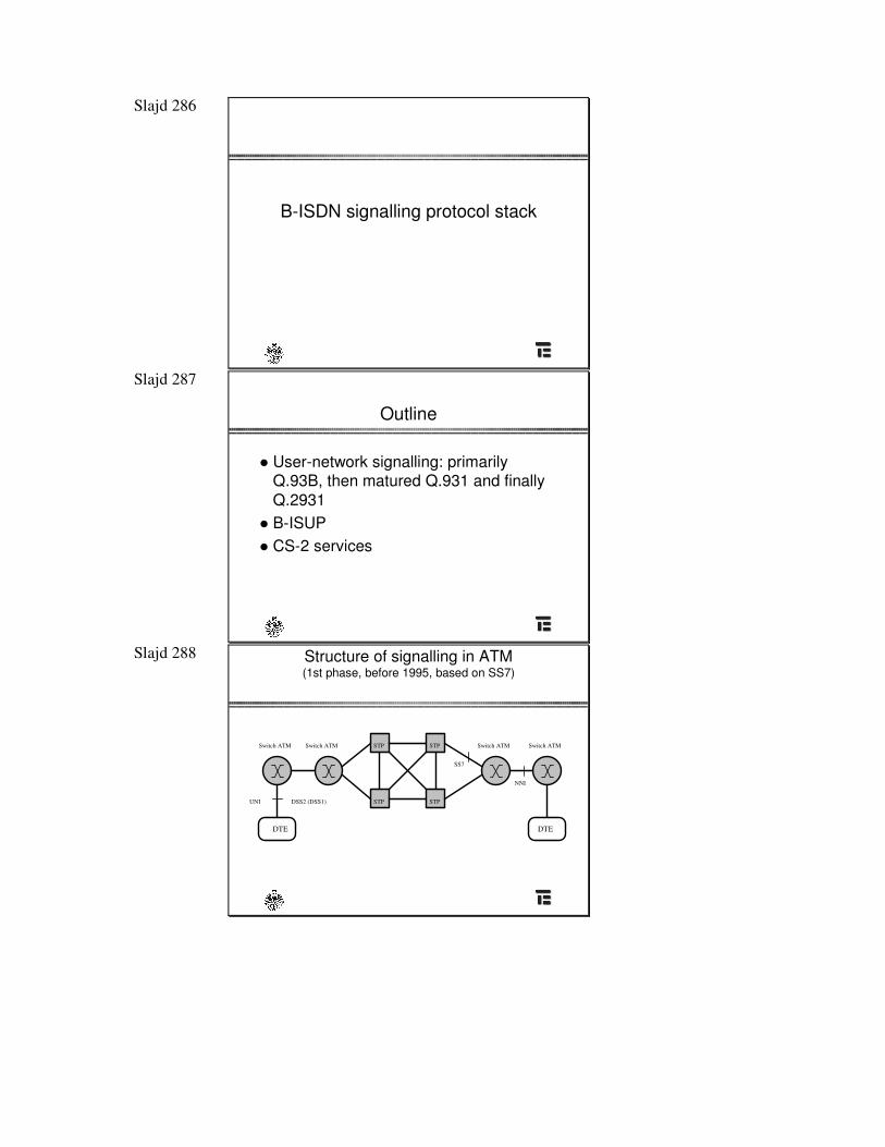
Slajd 286
B-ISDN signalling protocol stack
Slajd 287
Outline
� User-network signalling: primarilyQ.93B, then matured Q.931 and finallyQ.2931
� B-ISUP� CS-2 services
Slajd 288 Structure of signalling in ATM (1st phase, before 1995, based on SS7)
DTE DTE
STP STP
STP STPSwitch ATM Switch ATM Switch ATM Switch ATM
DSS2 (DSS1)UNI
NNI
SS7
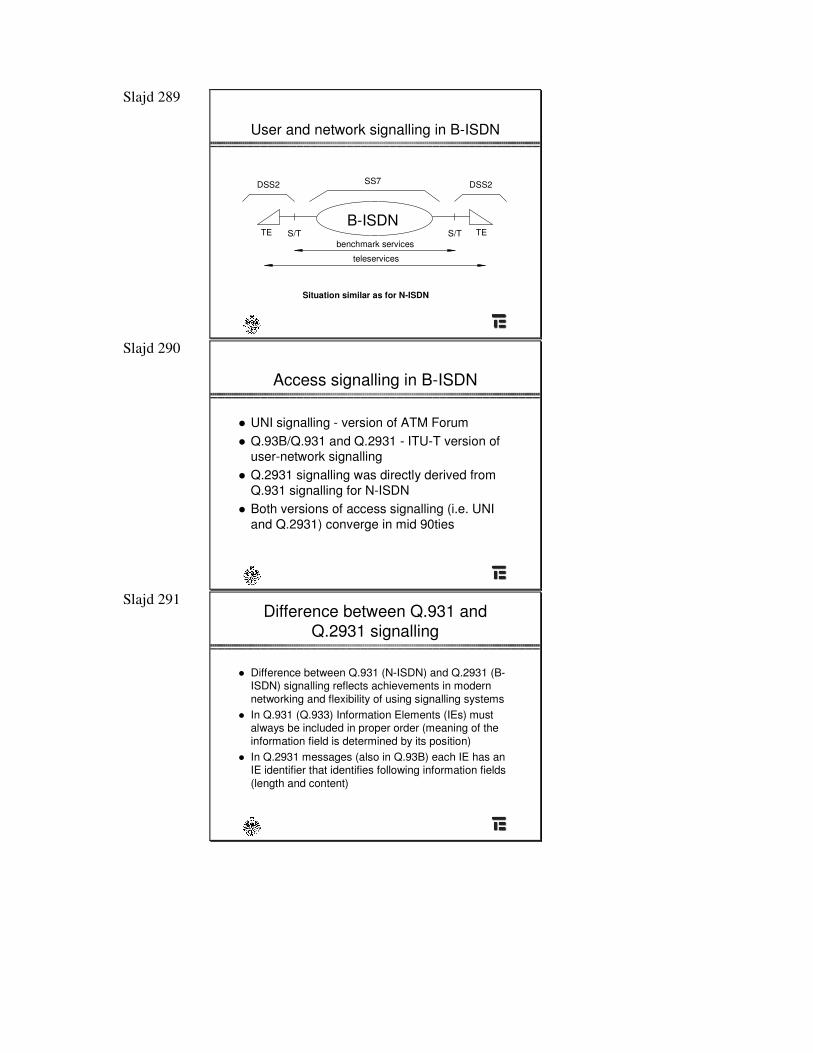
Slajd 289
User and network signalling in B-ISDN
SS7 DSS2DSS2
S/T S/TB-ISDN
benchmark services
teleservices
TE TE
Situation similar as for N-ISDN
Slajd 290
Access signalling in B-ISDN
� UNI signalling - version of ATM Forum� Q.93B/Q.931 and Q.2931 - ITU-T version of
user-network signalling� Q.2931 signalling was directly derived from
Q.931 signalling for N-ISDN� Both versions of access signalling (i.e. UNI
and Q.2931) converge in mid 90ties
Slajd 291 Difference between Q.931 and
Q.2931 signalling
� Difference between Q.931 (N-ISDN) and Q.2931 (B-ISDN) signalling reflects achievements in modernnetworking and flexibility of using signalling systems
� In Q.931 (Q.933) Information Elements (IEs) must always be included in proper order (meaning of the information field is determined by its position)
� In Q.2931 messages (also in Q.93B) each IE has anIE identifier that identifies following information fields(length and content)
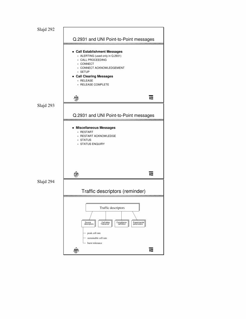
Slajd 292
Q.2931 and UNI Point-to-Point messages
� Call Establishment Messages» ALERTING (used only in Q.2931)» CALL PROCEEDING» CONNECT» CONNECT ACKNOWLEDGEMENT» SETUP
� Call Clearing Messages» RELEASE» RELEASE COMPLETE
Slajd 293
Q.2931 and UNI Point-to-Point messages
� Miscellaneous Messages» RESTART» RESTART ACKNOWLEDGE» STATUS» STATUS ENQUIRY
Slajd 294
Traffic descriptors (reminder)
Source descriptors
Cell delay Tolerance
Compliance definition parameters
Experimental
Traffic descriptors
peak cell rate
sustainable cell rate
burst tolerance
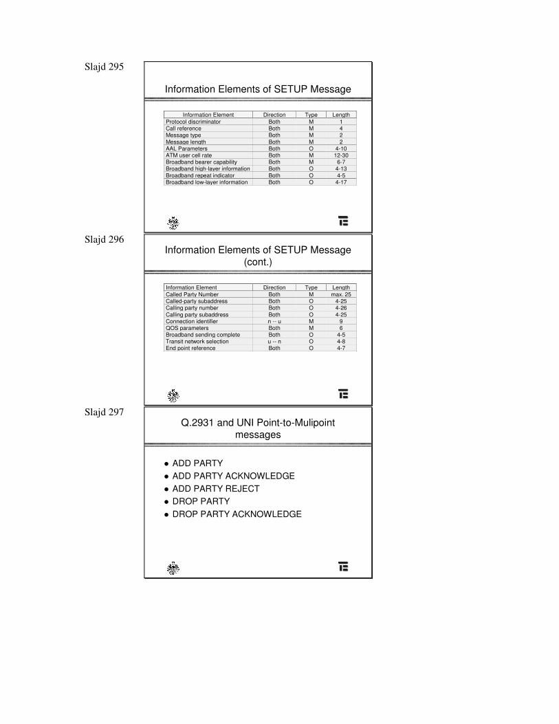
Slajd 295
Information Elements of SETUP Message
Information Element Direction Type LengthProtocol discriminator Both M 1Call reference Both M 4Message type Both M 2Message length Both M 2AAL Parameters Both O 4-10ATM user cell rate Both M 12-30Broadband bearer capability Both M 6-7Broadband high-layer information Both O 4-13Broadband repeat indicator Both O 4-5Broadband low-layer information Both O 4-17
Slajd 296 Information Elements of SETUP Message
(cont.)
Information Element Direction Type LengthCalled Party Number Both M max. 25Called-party subaddress Both O 4-25Calling party number Both O 4-26Calling party subaddress Both O 4-25Connection identifier n -- u M 9QOS parameters Both M 6Broadband sending complete Both O 4-5Transit network selection u -- n O 4-8End point reference Both O 4-7
Slajd 297 Q.2931 and UNI Point-to-Mulipoint
messages
� ADD PARTY� ADD PARTY ACKNOWLEDGE� ADD PARTY REJECT� DROP PARTY� DROP PARTY ACKNOWLEDGE
Slajd 298
Point-to-Mulipoint message significance
� ADD PARTY: sent to add party to an existing connection� ADD PARTY ACKNOWLEDGE: confirmation that the ADD
PARTY request was succesful� ADD PARTY REJECT: sent to acknowledge that the ADD
PARTY was not succesful� DROP PARTY: sent to drop a party from an existing point-to-
multipoint connection� DROP PARTY ACKNOWLEDGE: sent in response to a DROP
PARTY message to confirm that the party was dropped from the connection
Slajd 299
UNI signalling - briefing
� ATM Forum work� September 1993 UNI 3.0� September 1994 UNI 3.1 (15 releases)� Stable version – UNI 4.0 (July 1996)� Last version - UNI 4.1(April 2002)
Slajd 300
B-ISUP protocol stack
UNI NNI NNI
S-AAL
ATM ATM
S-AAL
MTP-3
Q.2931 B-ISUP
METASYG
Slajd 301
SAAL Layer
SSCOP
CPCS
SAR
SSCF
Q.93B
UNI
SSCF –Service SpecificCoordination Function
SSCOP –Service SpecificConnection-Oriented Protocol
CPCS –Common PartConvergence Sublayer
Slajd 302 Signalling ATM Adaptation Layer
Functions
� SSCOP (Service Specific Connection-Oriented Protocol):» Error correction (retransmissions)» Flow control» Error reporting» Maintenance (keep-alive)
� AAL Common Part (AAL 5 CP):» Unassured information transfer» Segmentation and reassembly» Cyclic redundancy checking
Slajd 303
Signalling is becoming more and more important ...
Thank you for your attention!
Slajd 1
Wojciech Dziunikowski, SSiZ, KT AGH
Plan wykładów – Zarządzanie
1. Wstęp do tematyki zarządzania2. Modelowanie informacji zarządzania3. Realizacja zarządzania w sieciach
teleinformatycznych4. Realizacja zarządzania w sieciach
telekomunikacyjnych5. Monitorowanie sieci
Slajd 2
Wojciech Dziunikowski, SSiZ, KT AGH
Literatura1. H.G. Hegering, S. Abeck, B. Neumair, Integrated
Management of Networked Systems, Concepts, Architectures, and Their Operational Application, Morgan Kaufmann, 1998.
2. W. Stallings: Protokoły SNMP i RMON, Vademecum profesjonalisty, Helion, Gliwice 2003.
3. P. Czarnecki, A. Jajszczyk, J. Lubacz: Standardy zarządzania sieciami OSI/NM, TMN, Wydawnictwa EFP, Poznań, 1995.
4. M. Subramanian: Network Management, Principles & Practice, Addison-Wesley, 1996.
5. M. Sloman: Network & Distributed Systems Management, Addison-Wesley, 2000.
Slajd 3
Wojciech Dziunikowski, SSiZ, KT AGH
Literatura
Strony WWW1. http://www.itlife.pl2. http://www.tmforum.org3. http://www.dmtf.org4. http://www.ietf.org
Slajd 4
Wojciech Dziunikowski, SSiZ, KT AGH
Definicja zarządzaniaDefinicja 1. Zarządzanie (ang. management) i
zarządzanie siecią (ang. network management) obejmuje zagadnienia związane z eksploatacją, administrowaniem, utrzymywaniem i uruchamianiem OMAP (ang. Operations, Maintenance, Administration and Provisioning) sieci telekomunikacyjnych i teleinformatycznych.
Definicja 2. Zarządzanie siecią jest to zespół czynności wykowanych przez operatora w celu jak najbardziej efektywnego wykorzystania zarządzanych zasobów oraz zapewnienia realizacji celów biznesowych przedsiębiorstwa.
Definicja 3. Zarządzanie są to wszelkie działania operatora mające na celu maksymalizację zysków.
Slajd 5
Wojciech Dziunikowski, SSiZ, KT AGH
Klasyfikacja zarządzania
Ze względu na rodzaj zarządzanych elementówtelekomunikacja vs. teleinformatykaZe względu na funkcjonalność obszary zarządzaniaZe względu na stosowane pojęcia warstwy zarządzaniaZe względu na horyzont czasowy
Slajd 6
Wojciech Dziunikowski, SSiZ, KT AGH
Rodzaj zarządzanych elementów
TeleinformatykaSieci komputerowe LAN/WANAplikacjeBackupyZdalne instalacje
oprogramowaniaZarządzanie problemami
Telekomunikacja�Sieci PDH, SDH, WDM, ATM�Centrale telefoniczne�Sieci dostępowe�Systemy radiowe�Systemy komórkowe
Tak jak w innych dziedzinach telekomunikacji i teleinformatyki, również w zarządzaniu następuje
integracja rozwiązań mających swe korzenie w obu tych obszarach
Slajd 7
Wojciech Dziunikowski, SSiZ, KT AGH
Funkcjonalność
Przykład 1Przypuśćmy, że węzeł komutacyjny sieci uległ
uszkodzeniu. Po wykryciu uszkodzenia węzeł ten zostaje wyłączony z sieci, a ruch skierowany inną drogą. Jednocześnie w sieci rozsyła się komunikat, że dane komutowane przez uszkodzony węzeł mogły ulec przekłamaniu oraz że opłaty za połączenia, które obsługiwał uszkodzony węzeł, mają zostać odpisane z kont użytkowników. Po naprawieniu uszkodzenia węzeł zostaje włączony do sieci oraz zostają przeprowadzone testy wydajności jego pracy.
Slajd 8
Wojciech Dziunikowski, SSiZ, KT AGH
Funkcjonalność (ITU X.700)
Funkcjonalne obszary zarządzania MFA (management functional areas) Zarządzanie uszkodzeniami (fault management)Zarządzanie konfiguracją (configuration management)Zarządzanie rozliczeniami (accounting management)Zarządzanie wydajnością (performance management)Zarządzanie bezpieczeństwem (security management)
Slajd 9
Wojciech Dziunikowski, SSiZ, KT AGH
Zarządzanie uszkodzeniami
Uszkodzenie (fault) jest to stan anormalny, którego usunięcie wymaga uwagi (lub interwencji) ze strony zarządcy. Nie należy utożsamiać uszkodzeń z błędami. Błąd to zdarzenie pojedyncze. Zazwyczaj możliwe jest skompensowanie błędów przez mechanizmy kontroli błędów w różnych protokołach. Uszkodzenie objawia się nieprawidłowym działaniem albo nadzwyczaj częstymi błędami.
Slajd 10
Wojciech Dziunikowski, SSiZ, KT AGH
Zarządzanie konfiguracją
Zarządzanie konfiguracją dotyczy głównie procesu uruchamiania sieci oraz sprawnego wyłączania jej części lub całości. Związane jest poza tym z utrzymywaniem, dodawaniem oraz uaktualnianiem powiązań między komponentami oraz kontrolą statusu tych komponentów w działającej sieci.
Użytkownicy końcowi często muszą lub chcą być informowani o stanie zasobów i komponentów sieciowych. Dlatego też, kiedy wystąpią zmiany w konfiguracji, użytkownicy powinni być o tych zmianach powiadamiani.
Slajd 11
Wojciech Dziunikowski, SSiZ, KT AGH
Zarządzanie rozliczeniamiAdministrator sieci z wielu powodów musi mieć możliwość śledzenia
używanych przez danego użytkownika (lub grupę określonych użytkowników) zasobów sieciowych. Przyczyny tego są następujące:użytkownik (lub grupa użytkowników końcowych) może nadużywać praw dostępu oraz obciążać sieć kosztem innych użytkowników,użytkownicy mogą wykorzystywać sieć mało efektywnie, a wtedy administrator sieci może pomóc zmienić procedury i wpłynąć na zwiększenie wydajności,administrator sieci jest w lepszej sytuacji wyjściowej do planowania rozbudowy sieci, jeżeli wystarczająco dokładnie zna wymagania i pola działalności użytkowników.
Slajd 12
Wojciech Dziunikowski, SSiZ, KT AGH
Zarządzanie wydajnością
Na zarządzanie wydajnością sieci składają się dwie rozległe kategorie funkcjonalne,monitorowanie – zestaw funkcji, dzięki którym można śledzić aktywność siecisterowanie – zestaw funkcji, umożliwiających osobie zarządzającej wprowadzanie poprawek podnoszących wydajność sieci.
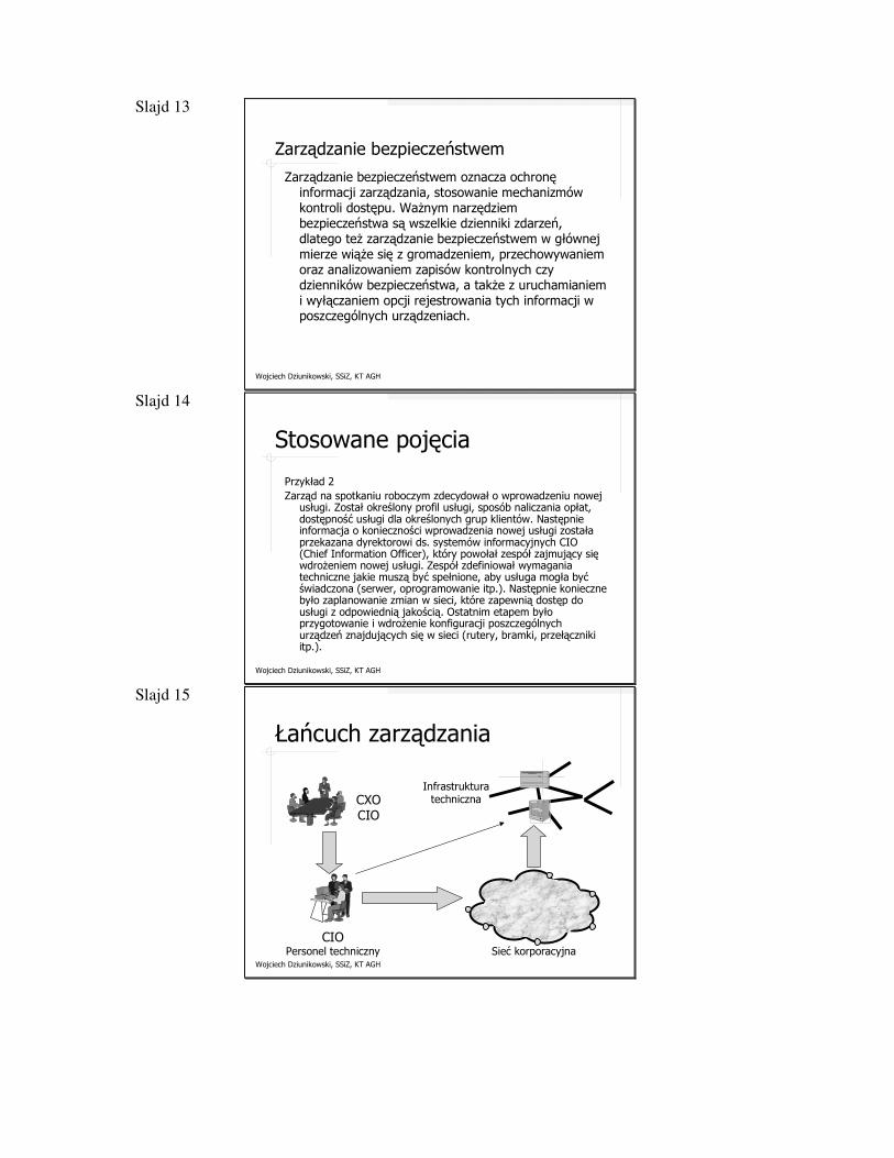
Slajd 13
Wojciech Dziunikowski, SSiZ, KT AGH
Zarządzanie bezpieczeństwem
Zarządzanie bezpieczeństwem oznacza ochronę informacji zarządzania, stosowanie mechanizmów kontroli dostępu. Ważnym narzędziem bezpieczeństwa są wszelkie dzienniki zdarzeń, dlatego też zarządzanie bezpieczeństwem w głównej mierze wiąże się z gromadzeniem, przechowywaniem oraz analizowaniem zapisów kontrolnych czy dzienników bezpieczeństwa, a także z uruchamianiem i wyłączaniem opcji rejestrowania tych informacji w poszczególnych urządzeniach.
Slajd 14
Wojciech Dziunikowski, SSiZ, KT AGH
Stosowane pojęcia
Przykład 2Zarząd na spotkaniu roboczym zdecydował o wprowadzeniu nowej
usługi. Został określony profil usługi, sposób naliczania opłat,dostępność usługi dla określonych grup klientów. Następnie informacja o konieczności wprowadzenia nowej usługi została przekazana dyrektorowi ds. systemów informacyjnych CIO (Chief Information Officer), który powołał zespół zajmujący się wdrożeniem nowej usługi. Zespół zdefiniował wymagania techniczne jakie muszą być spełnione, aby usługa mogła być świadczona (serwer, oprogramowanie itp.). Następnie konieczne było zaplanowanie zmian w sieci, które zapewnią dostęp do usługi z odpowiednią jakością. Ostatnim etapem było przygotowanie i wdrożenie konfiguracji poszczególnych urządzeń znajdujących się w sieci (rutery, bramki, przełączniki itp.).
Slajd 15
Wojciech Dziunikowski, SSiZ, KT AGH
Łańcuch zarządzania
CXOCIO
CIOPersonel techniczny Sieć korporacyjna
Infrastruktura techniczna
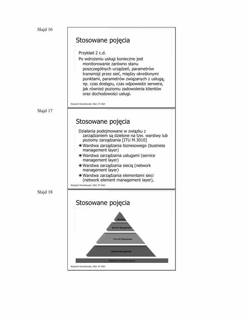
Slajd 16
Wojciech Dziunikowski, SSiZ, KT AGH
Stosowane pojęcia
Przykład 2 c.d.Po wdrożeniu usługi konieczne jest
monitorowanie zarówno stanu poszczególnych urządzeń, parametrów transmisji przez sieć, między określonymi punktami, parametrów związanych z usługą, np. czas dostępu, czas odpowiedzi serwera, jak również poziomu zadowolenia klientów oraz dochodowości usługi.
Slajd 17
Wojciech Dziunikowski, SSiZ, KT AGH
Stosowane pojęciaDziałania podejmowane w związku z
zarządzaniem są dzielone na tzw. warstwy lub poziomy zarządzania [ITU M.3010]Warstwa zarządzania biznesowego (business management layer)Warstwa zarządzania usługami (service management layer) Warstwa zarządzania siecią (network management layer)Warstwa zarządzania elementami sieci (network element management layer),
Slajd 18
Wojciech Dziunikowski, SSiZ, KT AGH
Stosowane pojęcia
Network infrastructure
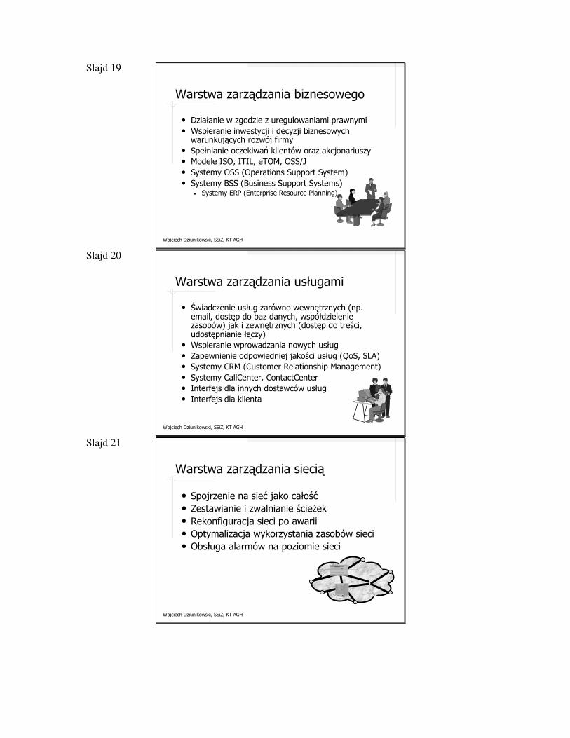
Slajd 19
Wojciech Dziunikowski, SSiZ, KT AGH
Warstwa zarządzania biznesowego
• Działanie w zgodzie z uregulowaniami prawnymi• Wspieranie inwestycji i decyzji biznesowych
warunkujących rozwój firmy• Spełnianie oczekiwań klientów oraz akcjonariuszy• Modele ISO, ITIL, eTOM, OSS/J• Systemy OSS (Operations Support System)• Systemy BSS (Business Support Systems)
• Systemy ERP (Enterprise Resource Planning)
Slajd 20
Wojciech Dziunikowski, SSiZ, KT AGH
Warstwa zarządzania usługami
• Świadczenie usług zarówno wewnętrznych (np. email, dostęp do baz danych, współdzielenie zasobów) jak i zewnętrznych (dostęp do treści, udostępnianie łączy)
• Wspieranie wprowadzania nowych usług• Zapewnienie odpowiedniej jakości usług (QoS, SLA)• Systemy CRM (Customer Relationship Management)• Systemy CallCenter, ContactCenter• Interfejs dla innych dostawców usług • Interfejs dla klienta
Slajd 21
Wojciech Dziunikowski, SSiZ, KT AGH
Warstwa zarządzania siecią
• Spojrzenie na sieć jako całość• Zestawianie i zwalnianie ścieżek• Rekonfiguracja sieci po awarii• Optymalizacja wykorzystania zasobów sieci• Obsługa alarmów na poziomie sieci
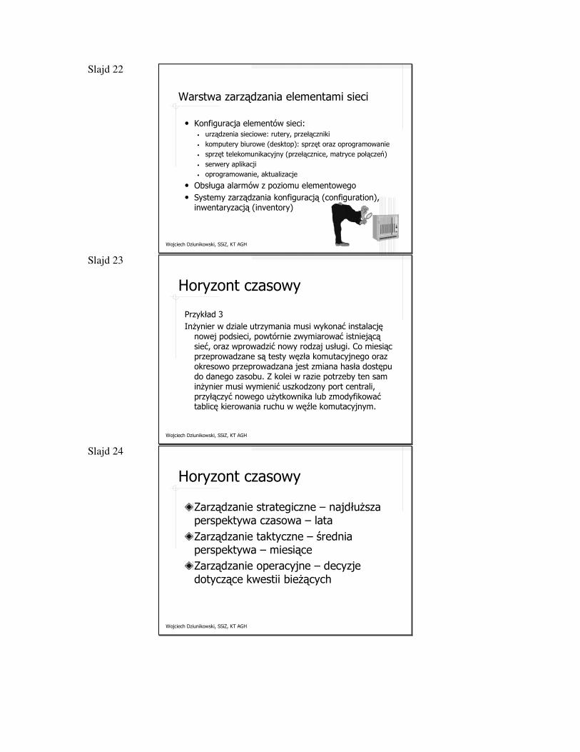
Slajd 22
Wojciech Dziunikowski, SSiZ, KT AGH
Warstwa zarządzania elementami sieci
• Konfiguracja elementów sieci: • urządzenia sieciowe: rutery, przełączniki• komputery biurowe (desktop): sprzęt oraz oprogramowanie• sprzęt telekomunikacyjny (przełącznice, matryce połączeń)• serwery aplikacji• oprogramowanie, aktualizacje
• Obsługa alarmów z poziomu elementowego• Systemy zarządzania konfiguracją (configuration),
inwentaryzacją (inventory)
Slajd 23
Wojciech Dziunikowski, SSiZ, KT AGH
Horyzont czasowy
Przykład 3Inżynier w dziale utrzymania musi wykonać instalację
nowej podsieci, powtórnie zwymiarować istniejącą sieć, oraz wprowadzić nowy rodzaj usługi. Co miesiąc przeprowadzane są testy węzła komutacyjnego oraz okresowo przeprowadzana jest zmiana hasła dostępu do danego zasobu. Z kolei w razie potrzeby ten sam inżynier musi wymienić uszkodzony port centrali, przyłączyć nowego użytkownika lub zmodyfikować tablicę kierowania ruchu w węźle komutacyjnym.
Slajd 24
Wojciech Dziunikowski, SSiZ, KT AGH
Horyzont czasowy
Zarządzanie strategiczne – najdłuższa perspektywa czasowa – lataZarządzanie taktyczne – średnia perspektywa – miesiąceZarządzanie operacyjne – decyzje dotyczące kwestii bieżących
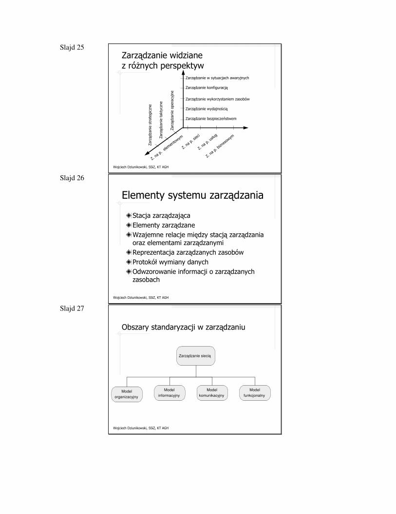
Slajd 25
Wojciech Dziunikowski, SSiZ, KT AGH
Zarządzanie widziane z różnych perspektyw
Zarządzanie w sytuacjach awaryjnych
Zarządzanie konfiguracją
Zarządzanie wykorzystaniem zasobów
Zarządzanie wydajnością
Zarządzanie bezpieczeństwem
Zarz
ądza
nie
stra
tegi
czne
Zarz
ądza
nie
takt
yczn
e
Zarz
ądza
nie
oper
acyj
ne
Z. na
p. e
lemen
towym
Z. na
p. si
eci
Z. na
p. us
ług
Z. na
p. bi
znes
owym
Slajd 26
Wojciech Dziunikowski, SSiZ, KT AGH
Elementy systemu zarządzania
Stacja zarządzającaElementy zarządzaneWzajemne relacje między stacją zarządzania oraz elementami zarządzanymiReprezentacja zarządzanych zasobówProtokół wymiany danychOdwzorowanie informacji o zarządzanych zasobach
Slajd 27
Wojciech Dziunikowski, SSiZ, KT AGH
Obszary standaryzacji w zarządzaniu
Model
organizacyjny
Model
informacyjny
Zarządzanie siecią
Model
komunikacyjny
Model
funkcjonalny
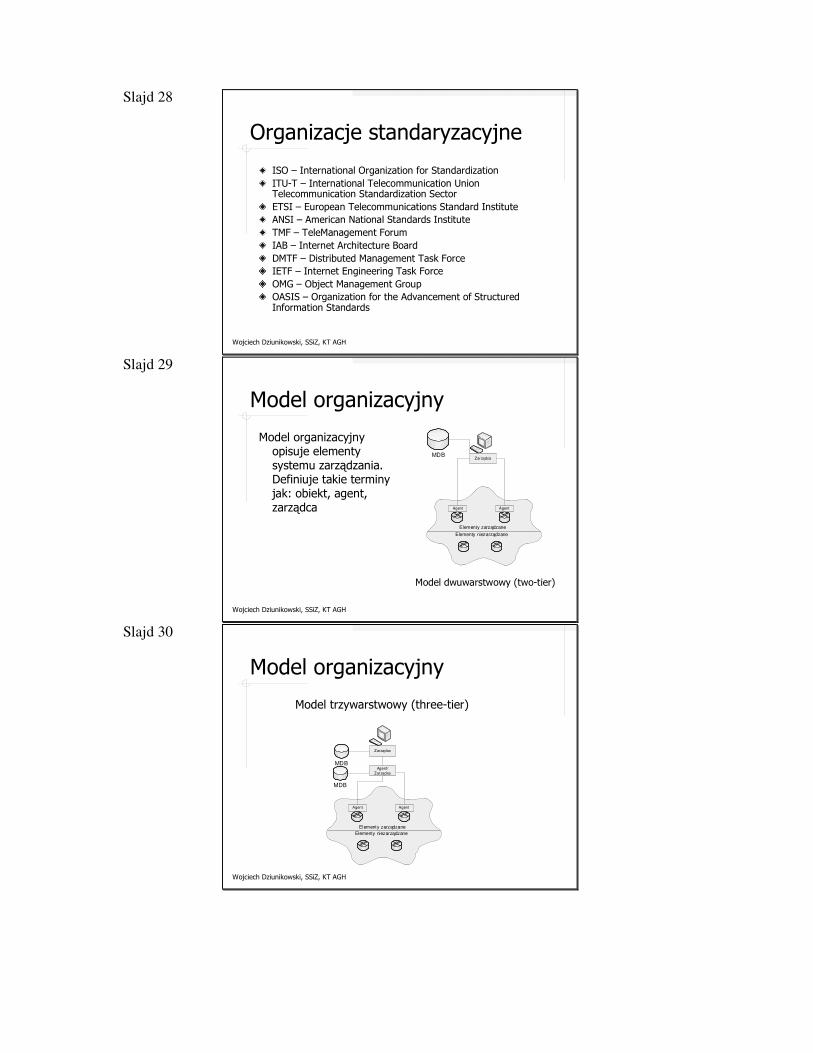
Slajd 28
Wojciech Dziunikowski, SSiZ, KT AGH
Organizacje standaryzacyjne
ISO – International Organization for StandardizationITU-T – International Telecommunication Union Telecommunication Standardization SectorETSI – European Telecommunications Standard InstituteANSI – American National Standards InstituteTMF – TeleManagement ForumIAB – Internet Architecture BoardDMTF – Distributed Management Task ForceIETF – Internet Engineering Task ForceOMG – Object Management GroupOASIS – Organization for the Advancement of Structured Information Standards
Slajd 29
Wojciech Dziunikowski, SSiZ, KT AGH
Model organizacyjny
Model organizacyjny opisuje elementy systemu zarządzania. Definiuje takie terminy jak: obiekt, agent, zarządca Agent Agent
ZarządcaMDB
Elementy zarządzane
Elementy niezarządzane
Model dwuwarstwowy (two-tier)
Slajd 30
Wojciech Dziunikowski, SSiZ, KT AGH
Model organizacyjny
Model trzywarstwowy (three-tier)
Agent Agent
Zarządca
Elementy zarządzane
Elementy niezarządzane
MDB
MDBAgent/
Zarządca
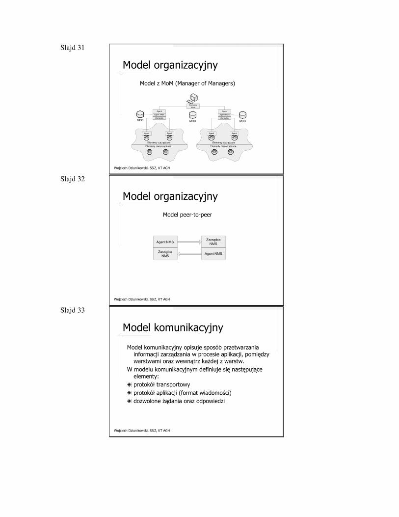
Slajd 31
Wojciech Dziunikowski, SSiZ, KT AGH
Model organizacyjny
Model z MoM (Manager of Managers)
Agent Agent
Zarządca MoM
Elementy zarządzane
Elementy niezarządzane
Zarządca
Agent NMS
MDB MDB
Agent Agent
Elementy zarządzane
Elementy niezarządzane
Agent
Zarządca
Agent NMS
Agent
MDB
Slajd 32
Wojciech Dziunikowski, SSiZ, KT AGH
Model organizacyjny
Model peer-to-peer
Agent NMS
Zarządca
NMS
Zarządca
NMS
Agent NMS
Slajd 33
Wojciech Dziunikowski, SSiZ, KT AGH
Model komunikacyjny
Model komunikacyjny opisuje sposób przetwarzania informacji zarządzania w procesie aplikacji, pomiędzy warstwami oraz wewnątrz każdej z warstw.
W modelu komunikacyjnym definiuje się następujące elementy:protokół transportowyprotokół aplikacji (format wiadomości)dozwolone żądania oraz odpowiedzi
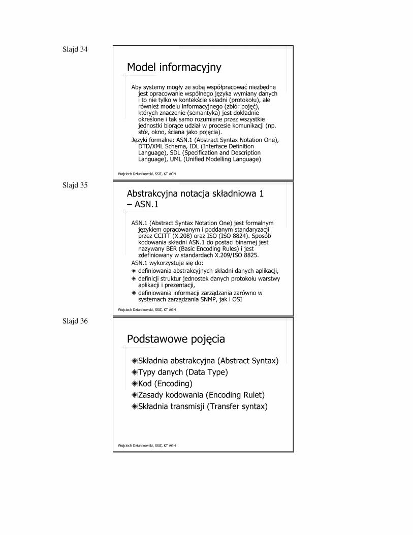
Slajd 34
Wojciech Dziunikowski, SSiZ, KT AGH
Model informacyjny
Aby systemy mogły ze sobą współpracować niezbędne jest opracowanie wspólnego języka wymiany danych i to nie tylko w kontekście składni (protokołu), ale również modelu informacyjnego (zbiór pojęć), których znaczenie (semantyka) jest dokładnie określone i tak samo rozumiane przez wszystkie jednostki biorące udział w procesie komunikacji (np. stół, okno, ściana jako pojęcia).
Języki formalne: ASN.1 (Abstract Syntax Notation One), DTD/XML Schema, IDL (Interface Definition Language), SDL (Specification and Description Language), UML (Unified Modelling Language)
Slajd 35
Wojciech Dziunikowski, SSiZ, KT AGH
Abstrakcyjna notacja składniowa 1 – ASN.1
ASN.1 (Abstract Syntax Notation One) jest formalnym językiem opracowanym i poddanym standaryzacji przez CCITT (X.208) oraz ISO (ISO 8824). Sposób kodowania składni ASN.1 do postaci binarnej jest nazywany BER (Basic Encoding Rules) i jest zdefiniowany w standardach X.209/ISO 8825.
ASN.1 wykorzystuje się do:definiowania abstrakcyjnych składni danych aplikacji,definicji struktur jednostek danych protokołu warstwy aplikacji i prezentacji,definiowania informacji zarządzania zarówno w systemach zarządzania SNMP, jak i OSI
Slajd 36
Wojciech Dziunikowski, SSiZ, KT AGH
Podstawowe pojęcia
Składnia abstrakcyjna (Abstract Syntax)Typy danych (Data Type)Kod (Encoding)Zasady kodowania (Encoding Rulet)Składnia transmisji (Transfer syntax)
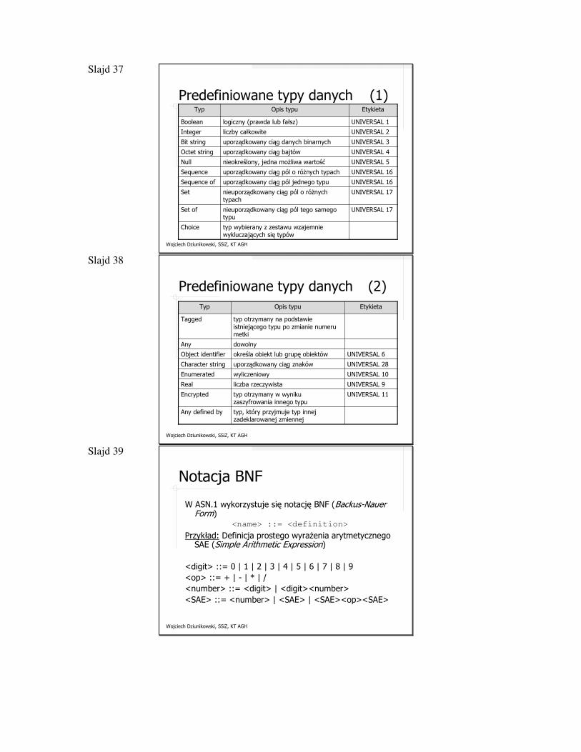
Slajd 37
Wojciech Dziunikowski, SSiZ, KT AGH
Predefiniowane typy danych (1)
typ wybierany z zestawu wzajemnie wykluczających się typów
Choice
UNIVERSAL 17nieuporządkowany ciąg pól tego samego typu
Set of
UNIVERSAL 17nieuporządkowany ciąg pól o różnych typach
Set
UNIVERSAL 16uporządkowany ciąg pól jednego typuSequence of
UNIVERSAL 16uporządkowany ciąg pól o różnych typachSequence
UNIVERSAL 5nieokreślony, jedna możliwa wartośćNull
UNIVERSAL 4uporządkowany ciąg bajtówOctet string
UNIVERSAL 3uporządkowany ciąg danych binarnychBit string
UNIVERSAL 2liczby całkowiteInteger
UNIVERSAL 1logiczny (prawda lub fałsz)Boolean
EtykietaOpis typuTyp
Slajd 38
Wojciech Dziunikowski, SSiZ, KT AGH
Predefiniowane typy danych (2)
UNIVERSAL 6określa obiekt lub grupę obiektówObject identifier
UNIVERSAL 28uporządkowany ciąg znakówCharacter string
UNIVERSAL 10wyliczeniowyEnumerated
UNIVERSAL 9liczba rzeczywistaReal
UNIVERSAL 11typ otrzymany w wyniku zaszyfrowania innego typu
Encrypted
typ, który przyjmuje typ innej zadeklarowanej zmiennej
Any defined by
dowolnyAny
typ otrzymany na podstawie istniejącego typu po zmianie numeru metki
Tagged
EtykietaOpis typuTyp
Slajd 39
Wojciech Dziunikowski, SSiZ, KT AGH
Notacja BNF
W ASN.1 wykorzystuje się notację BNF (Backus-Nauer Form)
<name> ::= <definition>
Przykład: Definicja prostego wyrażenia arytmetycznego SAE (Simple Arithmetic Expression)
<digit> ::= 0 | 1 | 2 | 3 | 4 | 5 | 6 | 7 | 8 | 9<op> ::= + | - | * | /<number> ::= <digit> | <digit><number><SAE> ::= <number> | <SAE> | <SAE><op><SAE>
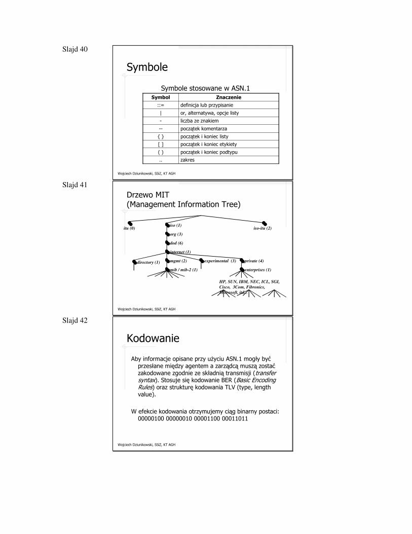
Slajd 40
Wojciech Dziunikowski, SSiZ, KT AGH
Symbole
Symbole stosowane w ASN.1
zakres..
początek i koniec podtypu( )
początek i koniec etykiety[ ]
początek i koniec listy{ }
początek komentarza--
liczba ze znakiem-
or, alternatywa, opcje listy|
definicja lub przypisanie::=
ZnaczenieSymbol
Slajd 41
Wojciech Dziunikowski, SSiZ, KT AGH
Drzewo MIT (Management Information Tree)
iso (1)iso-itu (2)itu (0)
org (3)
dod (6)
internet (1)
mgmt (2)
mib / mib-2 (1)
experimental (3) private (4)
enterprises (1)
HP, SUN, IBM, NEC, ICL, SGI,
Cisco, 3Com, Fibronics,
Microsoft, itd...
directory (1)
Slajd 42
Wojciech Dziunikowski, SSiZ, KT AGH
Kodowanie
Aby informacje opisane przy użyciu ASN.1 mogły być przesłane między agentem a zarządcą muszą zostać zakodowane zgodnie ze składnią transmisji (transfer syntax). Stosuje się kodowanie BER (Basic Encoding Rules) oraz strukturę kodowania TLV (type, lengthvalue).
W efekcie kodowania otrzymujemy ciąg binarny postaci: 00000100 00000010 00001100 00011011
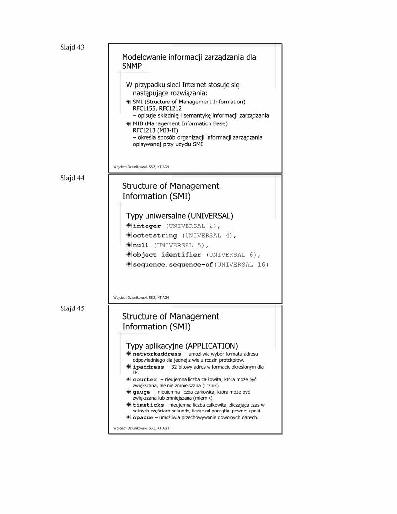
Slajd 43
Wojciech Dziunikowski, SSiZ, KT AGH
W przypadku sieci Internet stosuje się następujące rozwiązania:SMI (Structure of Management Information) RFC1155, RFC1212 – opisuje składnię i semantykę informacji zarządzaniaMIB (Management Information Base) RFC1213 (MIB-II)– określa sposób organizacji informacji zarządzania opisywanej przy użyciu SMI
Modelowanie informacji zarządzania dla SNMP
Slajd 44
Wojciech Dziunikowski, SSiZ, KT AGH
Structure of Management Information (SMI)
Typy uniwersalne (UNIVERSAL)integer (UNIVERSAL 2),
octetstring (UNIVERSAL 4),
null (UNIVERSAL 5),
object identifier (UNIVERSAL 6),
sequence,sequence-of(UNIVERSAL 16)
Slajd 45
Wojciech Dziunikowski, SSiZ, KT AGH
Structure of Management Information (SMI)
Typy aplikacyjne (APPLICATION)networkaddress – umożliwia wybór formatu adresu odpowiedniego dla jednej z wielu rodzin protokołów. ipaddress – 32-bitowy adres w formacie określonym dla IP,counter – nieujemna liczba całkowita, która może być zwiększana, ale nie zmniejszana (licznik) gauge – nieujemna liczba całkowita, która może być zwiększana lub zmniejszana (miernik)timeticks – nieujemna liczba całkowita, zliczająca czas w setnych częściach sekundy, licząc od początku pewnej epoki. opaque – umożliwia przechowywanie dowolnych danych.
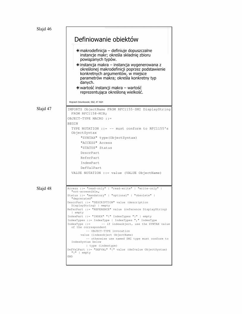
Slajd 46
Wojciech Dziunikowski, SSiZ, KT AGH
Definiowanie obiektów
makrodefinicja – definiuje dopuszczalne instancje makr; określa składnię zbioru powiązanych typów.instancja makra – instancja wygenerowana z określonej makrodefinicji poprzez podstawienie konkretnych argumentów, w miejsce parametrów makra; określa konkretny typ danych.wartość instancji makra – wartość reprezentująca określoną wielkość.
Slajd 47
Wojciech Dziunikowski, SSiZ, KT AGH
IMPORTS ObjectName FROM RFC1155-SMI DisplayString
FROM RFC1158-MIB;
OBJECT-TYPE MACRO ::=
BEGIN
TYPE NOTATION ::= -- must conform to RFC1155's
ObjectSyntax
"SYNTAX" type(ObjectSyntax)
"ACCESS" Access
"STATUS" Status
DescrPart
ReferPart
IndexPart
DefValPart
VALUE NOTATION ::= value (VALUE ObjectName)
Slajd 48
Wojciech Dziunikowski, SSiZ, KT AGH
Access ::= "read-only" | "read-write" | "write-only" |
"not-accessible„
Status ::= "mandatory" | "optional" | "obsolete" |
"deprecated"
DescrPart ::= "DESCRIPTION" value (description
DisplayString) | empty
ReferPart ::= "REFERENCE" value (reference DisplayString)
| empty
IndexPart ::= "INDEX" "{" IndexTypes "}" | empty
IndexTypes ::= IndexType | IndexTypes "," IndexType
IndexType ::= -- if indexobject, use the SYNTAX value
of the correspondent
-- OBJECT-TYPE invocation
value (indexobject ObjectName)
-- otherwise use named SMI type must conform to
IndexSyntax below
| type (indextype)
DefValPart ::= "DEFVAL" "{" value (defvalue ObjectSyntax)
"}" | empty
END
Slajd 49
Wojciech Dziunikowski, SSiZ, KT AGH
IndexSyntax ::= CHOICE {
number INTEGER (0..MAX),
string OCTET STRING,
object OBJECT IDENTIFIER,
address NetworkAddress,
ipAddress IpAddress }
Przykład definicji typu obiektu:
tcpMaxConn OBJECT-TYPE
SYNTAX INTEGER
ACCESS read-only
STATUS mandatory
DESCRIPTION
„Ograniczenie liczby połączeń TCP, które może
obsługiwać dana jednostka. W jednostkach, w których
maksymalna liczba połączeń jest dynamiczna, obiekt ten
powinien mieć wartość –1”
::= {tcp 4}
Slajd 50
Wojciech Dziunikowski, SSiZ, KT AGH
sysContact OBJECT-TYPE
SYNTAX DisplayString ( SIZE ( 0 .. 255 ) )
ACCESS read-write
STATUS mandatory
::= { system 4 }iso.org.dod.internet.mgmt
... ...
mib2 (1)
system (1)
sysDescr (1) sysUpTime (3) sysName (5) sysServices (7)sysContact (4)
sysContact.0wartość = „Janusz Gozdecki”
Definicja obiektu prostego
1.3.6.1.2
1.3.6.1.2.1.1.4.0
1.3.6.1.2.1.1
...
Slajd 51
Wojciech Dziunikowski, SSiZ, KT AGH
testTable OBJECT-TYPESYNTAX SEQUENCE OF TESTEntryACCESS not-accessible
STATUS mandatory::= { test 1 }
testEntry OBJECT-TYPESYNTAX TESTEntry
ACCESS not-accessibleINDEX { number }::= { testTable 1 }
TESTEntry ::= SEQUENCE {testNumber INTEGER,testName OCTET STRING }
testNumber OBJECT-TYPE
SYNTAX INTEGER...::= { testEntry 1 }
testTable (1)
testEntry (1)
testName OBJECT-TYPESYNTAX OCTET STRING...::= { testEntry 2 }
testNumber (1) testName (2)
Definicja obiektu tablicowego
Slajd 52
Wojciech Dziunikowski, SSiZ, KT AGH
Przykład - tablica tcpConnTable (RFC1213)
Obiekt tego typu, tabela połączeń TCP, zawiera informacje o połączeniach odnośnie danej jednostki zarządzania. W tabeli tej przechowywane są następujące informacje dla każdego połączenia:stan (State)adres lokalny (Local Address)port lokalny (Local Port)adres zdalny (Remote Address)port zdalny (Remote Port)
Slajd 53
Wojciech Dziunikowski, SSiZ, KT AGH
Tablica tcpConnTable (RFC1213)
tcpConnTable (1.3.6.1.2.1.6.13)
tcpConnEntry (tcpConnTable.1)
tcpConnState (tcpConnEntry.1)
tcpConnLocalAddress (tcpConnEntry.2)
tcpConnRemoteAddress (tcpConnEntry.4)
tcpConnRemotePort (tcpConnEntry.5)
tcpConnLocalPort (tcpConnEntry.3)
84149.156.114.2314149.156.114.13(synSent)
00.0.0.0990.0.0.02(listen)
15213.134.156.112149.156.114.15 (established)
indeks indeks indeks indeks
Slajd 54
Wojciech Dziunikowski, SSiZ, KT AGH
MIB vs. MDB
Agent Agent
ZarządcaMIBMDB
ISBN : number
Chapter_nr : number
Chapter_title : string
Figure_nr : numberFigure_title : string
ISBN = 0134377087
Chapter_nr = 3
Chapter_title = „Chapter 3"
Figure_nr = 1Figure_title = „Figure1"
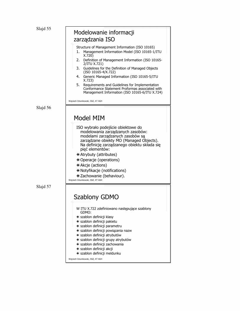
Slajd 55
Wojciech Dziunikowski, SSiZ, KT AGH
Modelowanie informacji zarządzania ISO
Structure of Management Information (ISO 10165)1. Management Information Model (ISO 10165-1/ITU
X.720)2. Definition of Management Information (ISO 10165-
2/ITU X.721)3. Guidelines for the Definition of Managed Objects
(ISO 10165-4/X.722)4. Generic Managed Information (ISO 10165-5/ITU
X.723) 5. Requirements and Guidelines for Implementation
Conformance Statement Proformas associated with Management Information (ISO 10165-6/ITU X.724)
Slajd 56
Wojciech Dziunikowski, SSiZ, KT AGH
Model MIMISO wybrało podejście obiektowe do
modelowania zarządzanych zasobów: modelami zarządzanych zasobów są zarządzane obiekty MO (Managed Objects). Na definicję zarządzanego obiektu składa się pięć elementów:Atrybuty (attributes)Operacje (operations)Akcje (actions)Notyfikacje (notifications)Zachowanie (behaviour).
Slajd 57
Wojciech Dziunikowski, SSiZ, KT AGH
Szablony GDMO
W ITU X.722 zdefiniowano następujące szablony GDMO:szablon definicji klasyszablon definicji pakietuszablon definicji parametruszablon definicji powiązania nazwszablon definicji atrybutówszablon definicji grupy atrybutówszablon definicji zachowaniaszablon definicji akcjiszablon definicji meldunku
Slajd 58
Wojciech Dziunikowski, SSiZ, KT AGH
Szablon definicji klasy GDMO
<class-label> MANAGED OBJECT CLASS
[DERIVED FROM <class-label> [,<class-label>]* ;
]
[CHARACTERIZED BY <package-label> [,<package-label>]* ;
]
[CONDITIONAL PACKAGES
<package-label> PRESENT IF condition-definition
[,<package-label> PRESENT IF condition-
definition]* ;
]
REGISTERED AS object-identifier ;
supporting productions
condition-definition -> delimited-string
Slajd 59
Wojciech Dziunikowski, SSiZ, KT AGH
Definicja klasy Systemsystem MANAGED OBJECT CLASS
DERIVED FROM top;
CHARACTERIZED BY
systemPackage PACKAGE
ATTRIBUTES
systemId GET,
systemTitle GET,
operationalState GET usageState GET;;;
CONDITIONAL PACKAGES
administrativeStatePackage PACKAGE
ATTRIBUTES
administrativeState GET-REPLACE ;
REGISTERED AS{smi2Package 14}; PRESENT IF "an instance supports it.",
supportedFeaturesPackage PACKAGE
ATTRIBUTES
supportedFeatures GET-REPLACE ADD-REMOVE;
REGISTERED AS{smi2Package 15}; PRESENT IF "an instance supports it.";
REGISTERED AS {smi2MObjectClass 13};
Slajd 60
Wojciech Dziunikowski, SSiZ, KT AGH
Podstawowe dokumenty RFC związane z SNMPRFC 1155: Structure and Identification of Management Information for
TCP/IP-based Internets
RFC 1156: : Management Information Base for Network Management for
TCP/IP-based Internets
RFC 1157: Simple Network Management Protocol
RFC 1213: Management Information Base for Network Management for
TCP/IP-based Internets: MIB II
RFC 2578: Structure of Management Information Version 2 (SMIv2)
RFC 2579: Textual Conventions for SMIv2
RFC 2580: Conformance Statements for SMIv2
Slajd 61
Wojciech Dziunikowski, SSiZ, KT AGH
Protokół SNMPv1
Specyfikacja protokołu SNMPv1 jest zamieszczona w RFC1157, opublikowanym w maju 1990 roku. Protokół ten jest rdzeniem zarządzania siecią za pomocą SNMP. Protokół warstwy aplikacji modelu OSI/ISOOparty w warstwie transportowej na bezpołączeniowym UDPJeden komunikat SNMP wymaga przesłania pojedynczego pakietu
Slajd 62
Wojciech Dziunikowski, SSiZ, KT AGH
Message ::= SEQUENCE {
version -- version-1 for this RFC
INTEGER {
version-1(0)
},
community -- community name
OCTET STRING,
data -- e.g., PDUs if trivial
ANY -- authentication is being used
}
Komunikat SNMP - Message
version community data (SNMP PDU)
Slajd 63
Wojciech Dziunikowski, SSiZ, KT AGH
Społeczność (community)
Społeczność SNMP jest związkiem między agentem SNMP a grupą zarządców SNMP, która definiuje właściwości uwierzytelniania, kontroli dostępu i pełnomocnictwa. Każdej społeczności nadana jest niepowtarzalna u danego agenta nazwa społeczności (Community Name), która jest przekazywana do stacji zarządzania należących do danej społeczności. Ponieważ społeczności definiowane są lokalnie u agenta, ta sama nazwa społeczności może być stosowana przez różnych agentów.
Slajd 64
Wojciech Dziunikowski, SSiZ, KT AGH
Klauzula ACCESS a tryb dostępu SNMP
niedostępnynot accessible
Get, Set i Trap (przy Get i Trap wartość zależy od implementacji)
Get i Trap (wartość zależy od
implementacji)
write-only
Get, Set i TrapGet i Trapread-write
Get i Trapread-only
READ-WRITEREAD-ONLY
Tryb dostępu SNMPKategoria ACCESS MIB
Slajd 65
Wojciech Dziunikowski, SSiZ, KT AGH
Rodzaje jednostek - PDUs
-- Protocol Data Units
PDUs ::= CHOICE {
get-request GetRequest-PDU,
get-next-request GetNextRequest-PDU,
get-response GetResponse-PDU,
set-request SetRequest-PDU,
trap Trap-PDU
}
-- Basic Protocol Data Units
GetRequest-PDU ::= [0] IMPLICIT PDU
GetNextRequest-PDU ::= [1] IMPLICIT PDU
GetResponse-PDU ::= [2] IMPLICIT PDU
SetRequest-PDU ::= [3] IMPLICIT PDU
Slajd 66
Wojciech Dziunikowski, SSiZ, KT AGH
Podstawowy rodzaj jednostki PDU
PDU ::= SEQUENCE {
request-id
INTEGER,
error-status -- sometimes ignored
INTEGER {
noError(0), tooBig(1), noSuchName(2),
badValue(3), readOnly(4), genErr(5)
},
error-index -- sometimes ignored
INTEGER,
variable-bindings -- values are sometimes ignored
VarBindList
}
PDU type request-id error-status error-index variable-bindings
Slajd 67
Wojciech Dziunikowski, SSiZ, KT AGH
Trap PDU (1)
Trap-PDU ::= [4] IMPLICIT SEQUENCE {
enterprise -- type of object generating
-- trap, see sysObjectID in
[5]
OBJECT IDENTIFIER,
agent-addr -- address of object
NetworkAddress, -- generating trap
generic-trap -- generic trap type
INTEGER {
coldStart(0), warmStart(1), linkDown(2),
linkUp(3), authenticationFailure(4),
egpNeighborLoss(5), enterpriseSpecific(6)
}, ...
PDU type
enterprise
agent-addr
generic-trap
variable-bindingsspecific-trap
time-stamp
Slajd 68
Wojciech Dziunikowski, SSiZ, KT AGH
Trap PDU (2)
.
.
.
specific-trap -- specific code, present even
INTEGER, -- if generic-trap is not
-- enterpriseSpecific
time-stamp -- time elapsed between the last
TimeTicks, -- (re)initialization of the
network
-- entity and the generation of
the trap
variable-bindings -- "interesting" information
VarBindList
}
PDU type
enterprise
agent-addr
generic-trap
variable-bindingsspecific-trap
time-stamp
Slajd 69
Wojciech Dziunikowski, SSiZ, KT AGH
Variable Bindings
VarBind ::= SEQUENCE {
name ObjectName,
value ObjectSyntax
}
VarBindList ::= SEQUENCE OF VarBind
nazwa1 wartość 1 nazwa 2 wartość 2 wartość n... nazwa n
Slajd 70
Wojciech Dziunikowski, SSiZ, KT AGH
Pobranie wartości obiektu (zmiennej)
Zarządca AgentPDU GetRequest
PDU GetResponse
PDU GetNextRequest
PDU GetResponse
...
Slajd 71
Wojciech Dziunikowski, SSiZ, KT AGH
Przykład - tablica tcpConnTable (RFC1213)
tcpConnTable (1.3.6.1.2.1.6.13)
tcpConnEntry (tcpConnTable.1)
tcpConnState (tcpConnEntry.1)
tcpConnLocalAddress (tcpConnEntry.2)
tcpConnRemoteAddress (tcpConnEntry.4)
tcpConnRemotePort (tcpConnEntry.5)
tcpConnLocalPort (tcpConnEntry.3)
84149.156.114.2314149.156.114.13(synSent)
00.0.0.0990.0.0.02(listen)
15213.134.156.112149.156.114.15 (established)
1.3.6.1.2.1.6.13.1.1.149.156.114.1.14.149.156.114.23.84
Slajd 72
Wojciech Dziunikowski, SSiZ, KT AGH
Usługi SNMP
Zarządca Agent
PDU SetRequest
PDU GetResponse
Ustawienie wartości obiektu (zmiennej)
Zarządca Agent
PDU Trap
Przekazanie informacji specjalnej
Slajd 73
Wojciech Dziunikowski, SSiZ, KT AGH
Podstawowe wady SNMPv11. Oficjalnie SNMP jest dedykowany jedynie dla sieci IP2. Jest nieefektywne w przypadku odczytywania dużych
tablic3. Tworzenie statystyk czasowych np. histogramów
ruchu w sieci z reguły wymaga generowania dużej liczby pakietów, co powoduje zwiększenie ruchu w zarządzanej sieci
4. Pułapki są niepotwierdzane.5. Brak zaawansowanego uwierzytelniania i szyfrowania.6. SNMP nie obsługuje bezpośrednio poleceń
imperatywnych.7. Model bazy MIB jest ograniczony.8. SNMP nie obsługuje komunikacji zarządca-zarządca.
Slajd 74
Wojciech Dziunikowski, SSiZ, KT AGH
Protokół SNMP v2Lipiec 1992 roku - Secure SNMP, SMP (Simple Management Protocol)SMP przyjęto jako punkt wyjścia przy opracowywaniu nowego standardu SNMP, znanego jako SNMP wersja 2 (SNMPv2)Marzec 1993 - SNMPv21996 - Community-Based SNMPv2 (SNMPv2c)
Slajd 75
Wojciech Dziunikowski, SSiZ, KT AGH
Protokół SNMP v2
Główne usprawnienia SNMP wprowadzone w SNMPv2 zawierają się w trzech kategoriach:struktura informacji zarządzania (SMI). SMI for SNMPv2 obejmuje cztery pojęcia:� definicje obiektów,� tabele,� definicje powiadomień,� moduły informacyjne.
Współpraca między zarządcami.Działanie protokołu.
Slajd 76
Wojciech Dziunikowski, SSiZ, KT AGH
Nowe klauzule makra OBJECT-TYPEUNITS
MAX-ACCESS
not-accesible, accessible-for-notify,
read-only, read-write, read-create
STATUS
ReferPart
DESCRIPTION
INDEX
AUGMENTS
DEFVAL
Slajd 77
Wojciech Dziunikowski, SSiZ, KT AGH
Klauzula MAX-ACCESS a tryb dostępu SNMPv2
Trapaccessible-for-notify
niedostępnynot accessible
Get, Set, Create i Trap Get i Trap write-only
Get, Set i TrapGet i Trapread-write
Get i Trapread-only
READ-WRITEREAD-ONLY
Tryb dostępu SNMPv2Kategoria MAX-
ACCESS MIB
Slajd 78
Wojciech Dziunikowski, SSiZ, KT AGH
Nowe makrodefinicje
TEXTUAL-CONVENTIONDateAndTime
(SYNTAX OCTET STRING (SIZE 8 | 11)))
TruthValue
(SYNTAX INTEGER {true(1), false(2) });
NOTIFICATION-TYPESTATUS, DESCRIPTION, OBJECTS
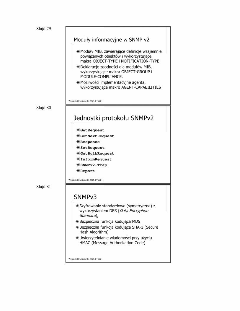
Slajd 79
Wojciech Dziunikowski, SSiZ, KT AGH
Moduły informacyjne w SNMP v2
Moduły MIB, zawierające definicje wzajemnie powiązanych obiektów i wykorzystujące makra OBJECT-TYPE i NOTIFICATION-TYPEDeklaracje zgodności dla modułów MIB, wykorzystujące makra OBJECT-GROUP i MODULE-COMPLIANCE.Możliwości implementacyjne agenta, wykorzystujące makro AGENT-CAPABILITIES
Slajd 80
Wojciech Dziunikowski, SSiZ, KT AGH
Jednostki protokołu SNMPv2
GetRequest
GetNextRequest
Response
SetRequest
GetBulkRequest
InformRequest
SNMPv2-Trap
Report
Slajd 81
Wojciech Dziunikowski, SSiZ, KT AGH
SNMPv3Szyfrowanie standardowe (symetryczne) z wykorzystaniem DES (Data EncryptionStandard),Bezpieczna funkcja kodująca MD5Bezpieczna funkcja kodująca SHA-1 (Secure Hash Algorithm)Uwierzytelnianie wiadomości przy użyciu HMAC (Message Authorization Code)
Slajd 82
Wojciech Dziunikowski, SSiZ, KT AGH
mib-2 (1)
system (1)
interfaces (2)
at (3) (deprecated)
ip (4)
icmp (5)
tcp (6)
udp (7
egp (8)
transmission (10)
snmp (11)
Grupa mib-2 - 1.3.6.1.2.1 (RFC1213)
...
...(MIB-I/MIB-II)
(22/23)
(3/3)
(33/38)
(26/26)
(17/19)
(4/7)
(6/18)
(x/0)
(x/30)
cmot (9) (x/0)
(3/7)
Slajd 83
Wojciech Dziunikowski, SSiZ, KT AGH
Grupa system – 1.3.6.1.2.1.1
system (mib-2 1)
sysDescr (1)
sysObjectID (2)
sysUpTime (3)
SysContact (4)
SysName (5)
sysLocation (6)
sysServices (7)
...
...
Slajd 84
Wojciech Dziunikowski, SSiZ, KT AGH
Grupa system – 1.3.6.1.2.1.1
Wartość wskazująca zestaw usług, które ta jednostka oferuje
ROINTEGER (0...127)
sysServices
Fizyczna lokalizacja tego węzłaRWDisplayString (SIZE (0...255))
sysLocation
Administracyjnie nadana nazwa tego węzła zarządzania
RWDisplayString (SIZE (0...255))
sysName
Identyfikacja oraz informacje kontaktowe z osobą obsługującą węzeł zarządzania
RWDisplayString (SIZE (0...255))
sysContact
Czas jaki upłynął od momentu ostatniej inicjalizacji części systemu związanej z zarządzaniem
ROTimeTickssysUpTime
Identyfikator podsystemu zarządzania siecią znajdującego się w danej jednostce, nadany przez producenta
ROOBJECT IDENTIFIERsysObjectID
Opis jednostki, np. używanego sprzętu, systemu operacyjnego itp..
RODisplayString (SIZE (0...255))
sysDescr
OpisDostępSkładniaObiekt
Slajd 85
Wojciech Dziunikowski, SSiZ, KT AGH
Grupa interfaces – 1.3.6.1.2.1.2
interfaces (mib-2 2)
ifNumber (1)
ifTable (2)
ifEntry (1)
...
ifSpeed (5)
ifType (3)
ifMtu (4)
ifIndex (1)
ifDescr (2)
...
ifAdminStatus (7)
ifOperStatus (8)
ifPhysAddress (6)
...
ifInUknownProtos (15)
ifInDiscards (13)
ifInErrors (14)
IfInUcastPkts (11)
IfInNUcastPkts (12)
ifLastChange (9)
ifInOctets (10)
...
ifOutUcastPkts (17)
ifOutNUcastPkts (18)
ifOutOctets (16)
ifOutQLen (21)
ifSpecific (22)
ifOutDiscards (19)
ifOutErrors (20)
Slajd 86
Wojciech Dziunikowski, SSiZ, KT AGH
Rozmiar największej jednostki danych protokołuROINTEGERifMtu
Szacunkowa wartość aktualnej przepustowości interfejsuROGaugeifSpeed
Adres interfejsu w protokole warstwy bezpośrednio poniżej warstwy sieci
ROPhysAddressifPhysAddress
Typ interfejsu określony na podstawie protokołu(ów) fizycznego (łącza)
ROINTEGERifType
Informacja o interfjesie zawierająca nazwę producenta, nazwę produktu oraz wersję sprzętową interfejsu
RODisplayString (SIZE (0...255))
ifDescr
Niepowtarzalna wartość dla każdego interfejsuROINTEGERifIndex
Wpis dla interfejsu zawierający obiekty z warstwy podsieci oraz warstw niższych
NASEQUENCEifEntry
Lista wpisów dla poszczególnych interfejsówNASEQUENCE OF ifEntry
ifTable
Liczba interfejsów sieciowychROINTEGERifNumber
OpisDostępSkładniaObiekt
Grupa interfaces – 1.3.6.1.2.1.2
Slajd 87
Wojciech Dziunikowski, SSiZ, KT AGH
Referencja do obiektów w bazie MIB zawierających specifyczne informacje o konkretnym medium wykorzystywanym do realizacji tego interfejsu
ROOBJECT IDENTIFIER
ifSpecific
Długość kolejki pakietów wychodzącychROGaugeifOutQLen
Wartość sysUpTime z chwili przełączenia się interfejsu na aktualny stan pracy
ROTimeTicksifLastChange
Bieżący stan interfejsu (up(1), down(2), testing(3))ROINTEGERifOperStatus
Żądany stan interfejsu (up(1), down(2), testing(3))RWINTEGERifAdminStatus
OpisDostępSkładniaObiekt
Grupa interfaces – 1.3.6.1.2.1.2
Slajd 88
Wojciech Dziunikowski, SSiZ, KT AGH
Grupa ip – 1.3.6.1.2.1.4
Informacje adresowe dla jednego z adresów IP tej jednostki
NASEQUENCEIpAddrEntry
Trasa do określonego miejsca przeznaczeniaNASEQUENCEIpRouteEntry
Wpis tabeli zawierający jeden adres IP dla jednego adresu fizycznego
NASEQUENCEIpNetToMediaEntry
Tabela translacji adresów IP, używana do odwzorowania adresów IP na adresy fizyczne
NASEQUENCE OF IpNetToMediaEntry
IpNetToMediaTable
Tablica trasowania IP tej jednostkiNASEQUENCE OF IpRouteEntry
IpRouteTable
Tabela informacji adresowych związanych z adresami IP tej jednostki
NASEQUENCE OF IpAddrEntry
IpAddrTable
Maksymalna liczba sekund, przez które odebrane fragmenty przetrzymywane są w oczekiwaniu na ponowne scalenie w kompletny datagram w tej jednostce
ROINTEGERIpReasmTimeout
Domyślna wartość wpisywana w pole TTL nagłówka datagramu IP wysyłanego przez tę jednostkę
RWINTEGERipDefaultTTL
1 – działanie jako bramka IP; 2 – działanie nie jako bramka IP
RWINTEGERipForwarding
OpisDostępSkładniaObiekt
Slajd 89
Wojciech Dziunikowski, SSiZ, KT AGH
Grupa ip – 1.3.6.1.2.1.4ipAddrTable
Rozmiar największego datagramu IP, który ta jednostka może ponownie scalić z datagramów przychodzących przez ten interfejs
ROINTEGERIpAdEntReasmMaxSize
Wartość najmniej znaczącego bitu w adresie rozgłoszeniowym używanym do wysyłania datagramów przez logiczny interfejs skojarzony z adresem IP z tego wiersza
ROINTEGERIpAdEntBcastAddr
Maska podsieci skojarzona z adresem IPROIpAddressIpAdEntNetMask
Wartość indeksu, niepowtarzalnie identyfikująca interfejs, do którego odnoszą się informacje z tego wiersza
ROINTEGERIpAdEntIfIndex
Adres IP, do którego odnoszą się informacje adresowe z tego wiersza
ROIpAddressIpAdEntAddr
OpisDostępSkładniaObiekt
Slajd 90
Wojciech Dziunikowski, SSiZ, KT AGH
Grupa ip – 1.3.6.1.2.1.4 ipRouteTable
Alternatywna metryka wyznaczania trasyRWINTEGERipRouteMetric5
Mechanizm zastosowany do wyznaczenia tej trasyRWINTEGERipRouteProto
Liczba sekund od chwili, gdy trasa została ostanio zaktualizowana lub zweryfikowana
RWINTEGERipRouteAge
Maska, która zostanie wymnożona logicznie (za pomocą funkcji AND) z adresem docelowym przed porównaniem go z adresem w ipRouteDest
RWIpAddressipRouteMask
Alternatywna metryka wyznaczania trasyRWINTEGERipRouteMetric3
Adres IP następnego węzła na trasieRWIpAddressipRouteNextHop
Referencja do części bazy MIB zawierającej informacje specyficzne dla protokołu trasowania stosowanego przy wyznaczaniu tej trasy
ROOBJECT IDENTIFIER
ipRouteInfo
other(1); invalid(2); direct(3); indirect(4)RWINTEGERipRouteType
Alternatywna metryka wyznaczania trasyRWINTEGERipRouteMetric4
Alternatywna metryka wyznaczania trasyRWINTEGERipRouteMetric2
Podstawowa metryka wyznaczania trasyRWINTEGERipRouteMetric1
Wartość indeksu, jednoznacznie identyfikująca lokalny interfejs, przez który powinny być wysyłane datagramy następnego etapu trasy
RWINTEGERipRouteIfIndex
Docelowy adres IP trasyRWIpAddressipRouteDest
OpisDostępSkładniaObiekt
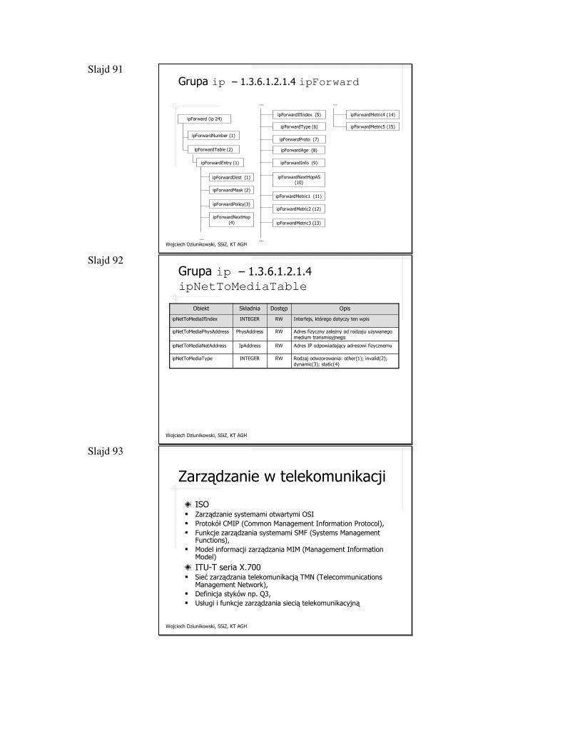
Slajd 91
Wojciech Dziunikowski, SSiZ, KT AGH
Grupa ip – 1.3.6.1.2.1.4 ipForward
ipForward (ip 24)
ipForwardNumber (1)
ipForwardTable (2)
ipForwardEntry (1)
...
ipForwardPolicy(3)
ipForwardNextHop (4)
ipForwardDest (1)
ipForwardMask (2)
...
ipForwardType (6)
ipForwardProto (7)
ipForwardIfIndex (5)
...
ipForwardMetric3 (13)
ipForwardMetric1 (11)
ipForwardMetric2 (12)
ipForwardNextHopAS(10)
ipForwardAge (8)
ipForwardInfo (9)
...
ipForwardMetric5 (15)
ipForwardMetric4 (14)
Slajd 92
Wojciech Dziunikowski, SSiZ, KT AGH
Grupa ip – 1.3.6.1.2.1.4ipNetToMediaTable
Rodzaj odwzorowania: other(1); invalid(2); dynamic(3); static(4)
RWINTEGERipNetToMediaType
Adres IP odpowiadający adresowi fizycznemuRWIpAddressipNetToMediaNetAddress
Adres fizyczny zależny od rodzaju używanego medium transmisyjnego
RWPhysAddressipNetToMediaPhysAddress
Interfejs, którego dotyczy ten wpisRWINTEGERipNetToMediaIfIndex
OpisDostępSkładniaObiekt
Slajd 93
Wojciech Dziunikowski, SSiZ, KT AGH
Zarządzanie w telekomunikacji
ISO� Zarządzanie systemami otwartymi OSI� Protokół CMIP (Common Management Information Protocol), � Funkcje zarządzania systemami SMF (Systems Management
Functions), � Model informacji zarządzania MIM (Management Information
Model)
ITU-T seria X.700� Sieć zarządzania telekomunikacją TMN (Telecommunications
Management Network), � Definicja styków np. Q3, � Usługi i funkcje zarządzania siecią telekomunikacyjną
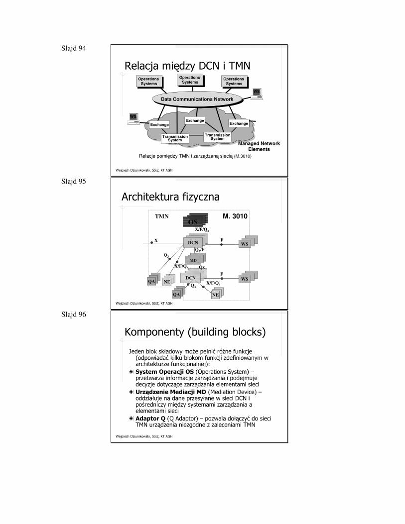
Slajd 94
Wojciech Dziunikowski, SSiZ, KT AGH
Relacja między DCN i TMN
Relacje pomiędzy TMN i zarządzaną siecią (M.3010)
Managed Network Elements
Data Communications Network
WS
WS
Operations
Systems
ExchangeExchange
TransmissionSystem
Operations
SystemsOperations
Systems
Exchange
TransmissionSystem
Slajd 95
Wojciech Dziunikowski, SSiZ, KT AGH
Q3/F
Q3
X/F/Q3
QX
X/F/Q3
F
F
X
TMNOS
NE
NE
DCN
DCN
Qx
QA
QA
MD
WS
WS
X/F/Q3
M. 3010
Architektura fizyczna
Slajd 96
Wojciech Dziunikowski, SSiZ, KT AGH
Komponenty (building blocks)
Jeden blok składowy może pełnić różne funkcje (odpowiadać kilku blokom funkcji zdefiniowanym w architekturze funkcjonalnej):System Operacji OS (Operations System) –przetwarza informacje zarządzania i podejmuje decyzje dotyczące zarządzania elementami sieciUrządzenie Mediacji MD (Mediation Device) –oddziałuje na dane przesyłane w sieci DCN i pośredniczy między systemami zarządzania a elementami sieciAdaptor Q (Q Adaptor) – pozwala dołączyć do sieci TMN urządzenia niezgodne z zaleceniami TMN
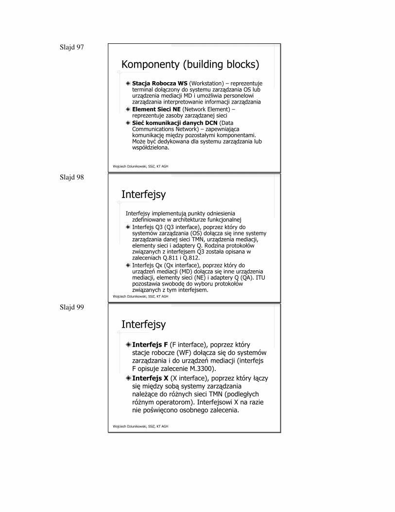
Slajd 97
Wojciech Dziunikowski, SSiZ, KT AGH
Komponenty (building blocks)
Stacja Robocza WS (Workstation) – reprezentuje terminal dołączony do systemu zarządzania OS lub urządzenia mediacji MD i umożliwia personelowi zarządzania interpretowanie informacji zarządzaniaElement Sieci NE (Network Element) –reprezentuje zasoby zarządzanej sieciSieć komunikacji danych DCN (Data Communications Network) – zapewniająca komunikację między pozostałymi komponentami. Może być dedykowana dla systemu zarządzania lub współdzielona.
Slajd 98
Wojciech Dziunikowski, SSiZ, KT AGH
Interfejsy
Interfejsy implementują punkty odniesienia zdefiniowane w architekturze funkcjonalnejInterfejs Q3 (Q3 interface), poprzez który do systemów zarządzania (OS) dołącza się inne systemy zarządzania danej sieci TMN, urządzenia mediacji, elementy sieci i adaptery Q. Rodzina protokołów związanych z interfejsem Q3 została opisana w zaleceniach Q.811 i Q.812.Interfejs Qx (Qx interface), poprzez który do urządzeń mediacji (MD) dołącza się inne urządzenia mediacji, elementy sieci (NE) i adaptery Q (QA). ITU pozostawia swobodę do wyboru protokołów związanych z tym interfejsem.
Slajd 99
Wojciech Dziunikowski, SSiZ, KT AGH
Interfejsy
Interfejs F (F interface), poprzez który stacje robocze (WF) dołącza się do systemów zarządzania i do urządzeń mediacji (interfejs F opisuje zalecenie M.3300).Interfejs X (X interface), poprzez który łączy się między sobą systemy zarządzania należące do różnych sieci TMN (podległych różnym operatorom). Interfejsowi X na razie nie poświęcono osobnego zalecenia.
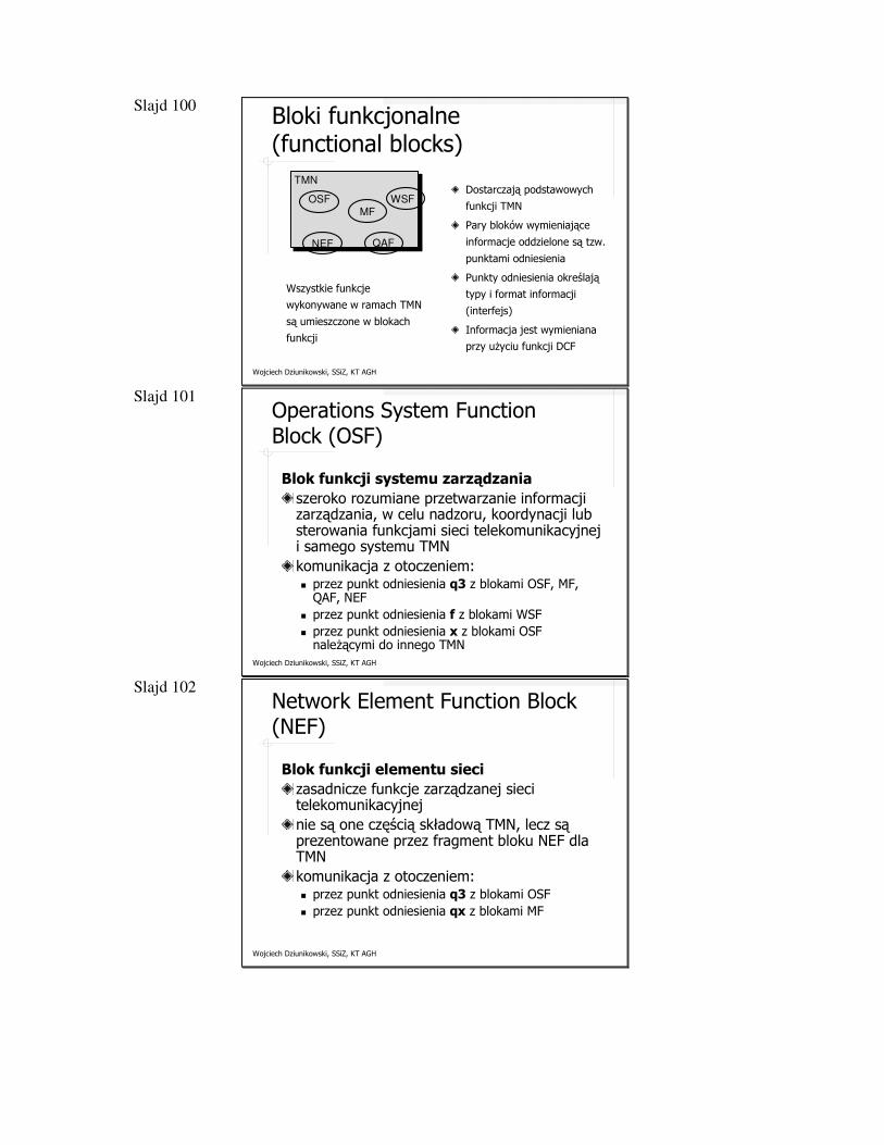
Slajd 100
Wojciech Dziunikowski, SSiZ, KT AGH
Bloki funkcjonalne (functional blocks)
OSF
TMN
MFWSF
NEF QAF
Dostarczają podstawowych
funkcji TMN
Pary bloków wymieniające
informacje oddzielone są tzw.
punktami odniesienia
Punkty odniesienia określają
typy i format informacji
(interfejs)
Informacja jest wymieniana
przy użyciu funkcji DCF
Wszystkie funkcje
wykonywane w ramach TMN
są umieszczone w blokach
funkcji
Slajd 101
Wojciech Dziunikowski, SSiZ, KT AGH
Operations System Function Block (OSF)
Blok funkcji systemu zarządzania
szeroko rozumiane przetwarzanie informacji zarządzania, w celu nadzoru, koordynacji lub sterowania funkcjami sieci telekomunikacyjnej i samego systemu TMNkomunikacja z otoczeniem:� przez punkt odniesienia q3 z blokami OSF, MF,
QAF, NEF� przez punkt odniesienia f z blokami WSF� przez punkt odniesienia x z blokami OSF
należącymi do innego TMN
Slajd 102
Wojciech Dziunikowski, SSiZ, KT AGH
Network Element Function Block (NEF)
Blok funkcji elementu sieci
zasadnicze funkcje zarządzanej sieci telekomunikacyjnejnie są one częścią składową TMN, lecz są prezentowane przez fragment bloku NEF dla TMNkomunikacja z otoczeniem:� przez punkt odniesienia q3 z blokami OSF� przez punkt odniesienia qx z blokami MF
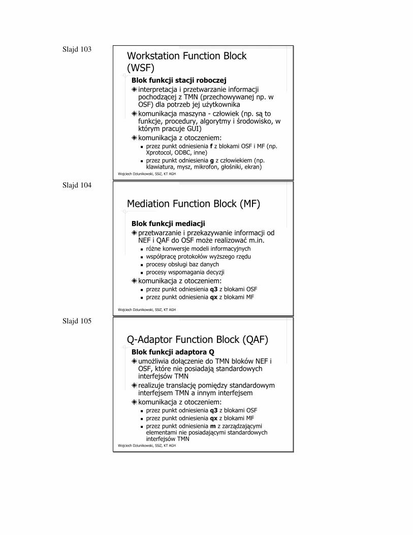
Slajd 103
Wojciech Dziunikowski, SSiZ, KT AGH
Workstation Function Block (WSF)Blok funkcji stacji roboczej
interpretacja i przetwarzanie informacji pochodzącej z TMN (przechowywanej np. w OSF) dla potrzeb jej użytkownikakomunikacja maszyna - człowiek (np. są to funkcje, procedury, algorytmy i środowisko, w którym pracuje GUI)komunikacja z otoczeniem:� przez punkt odniesienia f z blokami OSF i MF (np.
Xprotocol, ODBC, inne)� przez punkt odniesienia g z człowiekiem (np.
klawiatura, mysz, mikrofon, głośniki, ekran)
Slajd 104
Wojciech Dziunikowski, SSiZ, KT AGH
Mediation Function Block (MF)
Blok funkcji mediacji
przetwarzanie i przekazywanie informacji od NEF i QAF do OSF może realizować m.in. � różne konwersje modeli informacyjnych� współpracę protokołów wyższego rzędu� procesy obsługi baz danych� procesy wspomagania decyzji
komunikacja z otoczeniem:� przez punkt odniesienia q3 z blokami OSF� przez punkt odniesienia qx z blokami MF
Slajd 105
Wojciech Dziunikowski, SSiZ, KT AGH
Q-Adaptor Function Block (QAF)Blok funkcji adaptora Q
umożliwia dołączenie do TMN bloków NEF i OSF, które nie posiadają standardowych interfejsów TMNrealizuje translację pomiędzy standardowym interfejsem TMN a innym interfejsemkomunikacja z otoczeniem:� przez punkt odniesienia q3 z blokami OSF� przez punkt odniesienia qx z blokami MF� przez punkt odniesienia m z zarządzającymi
elementami nie posiadającymi standardowych interfejsów TMN
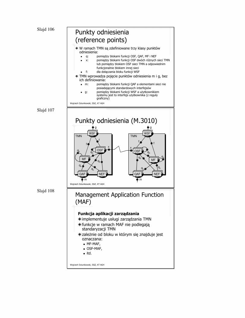
Slajd 106
Wojciech Dziunikowski, SSiZ, KT AGH
Punkty odniesienia (reference points)
W ramach TMN są zdefiniowane trzy klasy punktów odniesienia:� q: pomiędzy blokami funkcji OSF, QAF, MF i NEF� x: pomiędzy blokami funkcji OSF dwóch różnych sieci TMN
lub pomiędzy blokiem OSF sieci TMN a odpowiednimfunkcjonalnie blokiem innej sieci
� f: dla dołączania bloku funkcji WSF
TMN wprowadza pojęcie punktów odniesienia m i g, bez ich definiowania:� m: pomiędzy blokami funkcji QAF a elementami sieci nie
posiadającymi standardowych interfejsów� g: pomiędzy blokami funkcji WSF a użytkownikiem
systemu jest to interfejs użytkownika (z reguły graficzny)
Slajd 107
Wojciech Dziunikowski, SSiZ, KT AGH
Punkty odniesienia (M.3010)
TMN
MFMF
QAF NEF
OSF
WSF
f
f
g
q3
q3
qx
qx
qx
x
m
TMN
MFMF
QAF NEF
OSF
WSF
ff
g
q3
q3
qx
qxqx
x
m
Slajd 108
Wojciech Dziunikowski, SSiZ, KT AGH
Management Application Function (MAF)
Funkcja aplikacji zarządzania
implementuje usługi zarządzania TMNfunkcje w ramach MAF nie podlegają standaryzacji TMNzależnie od bloku w którym się znajduje jest oznaczana:� MF-MAF, � OSF-MAF,� itd.
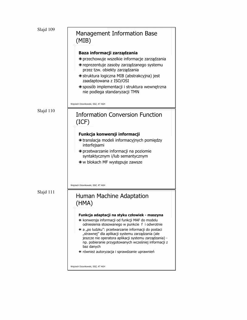
Slajd 109
Wojciech Dziunikowski, SSiZ, KT AGH
Management Information Base (MIB)
Baza informacji zarządzania
przechowuje wszelkie informacje zarządzaniareprezentuje zasoby zarządzanego systemu przez tzw. obiekty zarządzaniastruktura logiczna MIB (abstrakcyjna) jest zaadaptowana z ISO/OSIsposób implementacji i struktura wewnętrzna nie podlega standaryzacji TMN
Slajd 110
Wojciech Dziunikowski, SSiZ, KT AGH
Information Conversion Function (ICF)
Funkcja konwersji informacji
translacja modeli informacyjnych pomiędzy interfejsamiprzetwarzanie informacji na poziomie syntaktycznym i/lub semantycznymw blokach MF występuje zawsze
Slajd 111
Wojciech Dziunikowski, SSiZ, KT AGH
Human Machine Adaptation (HMA)
Funkcja adaptacji na styku człowiek - maszyna
konwersja informacji od funkcji MAF do modelu odniesienia stosowanego w punkcie f i odwrotniea „po ludzku”: przetwarzanie informacji do postaci „strawnej” dla aplikacji systemu zarządzania (ale jeszcze nie operatora aplikacji systemu zarządzania) -np. pobieranie przygotowanych wcześniej informacji z baz danychrównież autoryzacja i sprawdzanie uprawnień
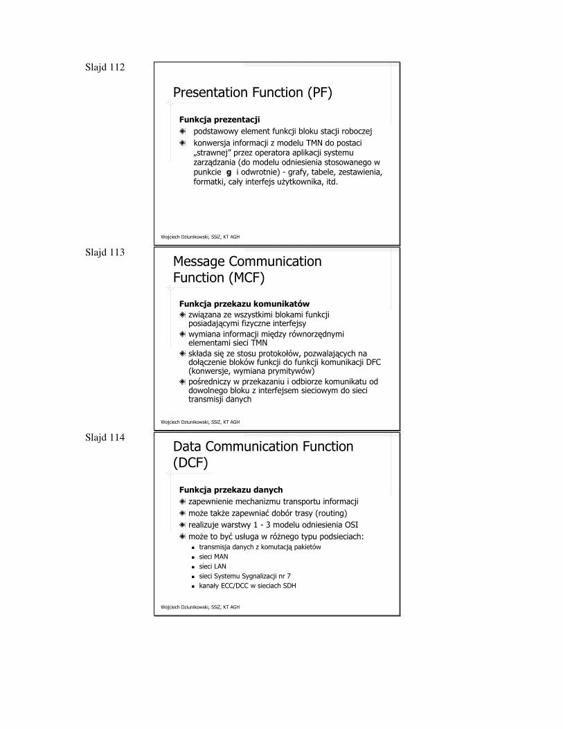
Slajd 112
Wojciech Dziunikowski, SSiZ, KT AGH
Presentation Function (PF)
Funkcja prezentacji
podstawowy element funkcji bloku stacji roboczejkonwersja informacji z modelu TMN do postaci „strawnej” przez operatora aplikacji systemu zarządzania (do modelu odniesienia stosowanego w punkcie g i odwrotnie) - grafy, tabele, zestawienia, formatki, cały interfejs użytkownika, itd.
Slajd 113
Wojciech Dziunikowski, SSiZ, KT AGH
Message Communication Function (MCF)
Funkcja przekazu komunikatów
związana ze wszystkimi blokami funkcji posiadającymi fizyczne interfejsywymiana informacji między równorzędnymi elementami sieci TMNskłada się ze stosu protokołów, pozwalających na dołączenie bloków funkcji do funkcji komunikacji DFC (konwersje, wymiana prymitywów)pośredniczy w przekazaniu i odbiorze komunikatu od dowolnego bloku z interfejsem sieciowym do sieci transmisji danych
Slajd 114
Wojciech Dziunikowski, SSiZ, KT AGH
Data Communication Function (DCF)
Funkcja przekazu danych
zapewnienie mechanizmu transportu informacjimoże także zapewniać dobór trasy (routing)realizuje warstwy 1 - 3 modelu odniesienia OSImoże to być usługa w różnego typu podsieciach:� transmisja danych z komutacją pakietów� sieci MAN� sieci LAN� sieci Systemu Sygnalizacji nr 7� kanały ECC/DCC w sieciach SDH
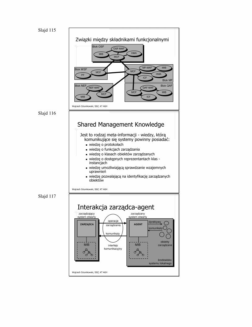
Slajd 115
Wojciech Dziunikowski, SSiZ, KT AGH
Związki między składnikami funkcjonalnymi
OSF-MAF
MIB HMA
PF
MIBMF-MAF
HMA
ICF
MIB
QAF-MAF
ICFMIB
NEF-MAF
MCF
MCF MCF
MCFMCF
Blok MF
Blok QAFBlok NEF
Blok WSF
Blok OSF
Slajd 116
Wojciech Dziunikowski, SSiZ, KT AGH
Shared Management Knowledge
Jest to rodzaj meta-informacji - wiedzy, którą komunikujące się systemy powinny posiadać:� wiedzę o protokołach� wiedzę o funkcjach zarządzania� wiedzę o klasach obiektów zarządzanych� wiedzę o dostępnych reprezentantach klas -
instancjach� wiedzę umożliwiającą sprawdzanie wzajemnych
uprawnień� wiedzę pozwalającą na identyfikację zarządzanych
obiektów
Slajd 117
Wojciech Dziunikowski, SSiZ, KT AGH
Interakcja zarządca-agent
MIB
ZARZĄDCA
MIB
AGENT
zarządzający
system otwarty
zarządzany
system otwarty
obiekty
zarządzane
dyrektywy
komunikaty
środowisko
systemu lokalnego
operacje
zarządzania
komunikaty
interfejs
komunikacyjny
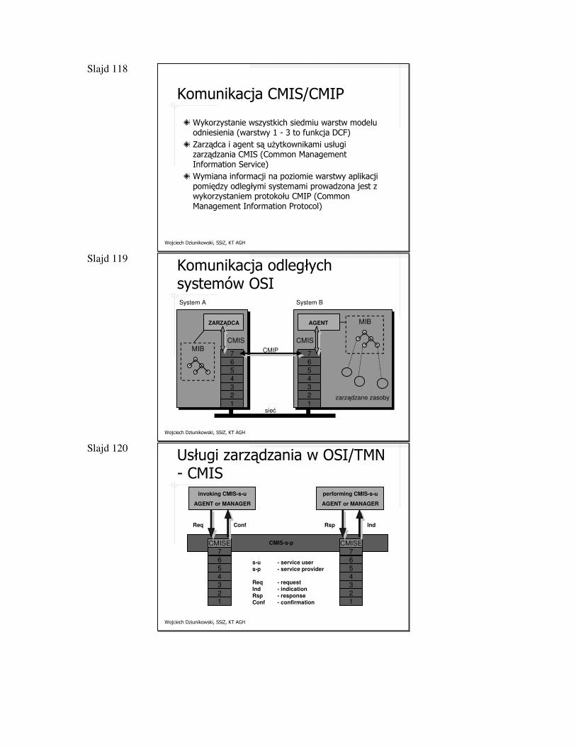
Slajd 118
Wojciech Dziunikowski, SSiZ, KT AGH
Komunikacja CMIS/CMIP
Wykorzystanie wszystkich siedmiu warstw modelu odniesienia (warstwy 1 - 3 to funkcja DCF)Zarządca i agent są użytkownikami usługi zarządzania CMIS (Common ManagementInformation Service)Wymiana informacji na poziomie warstwy aplikacji pomiędzy odległymi systemami prowadzona jest z wykorzystaniem protokołu CMIP (Common Management Information Protocol)
Slajd 119
Wojciech Dziunikowski, SSiZ, KT AGH
Komunikacja odległych systemów OSI
MIB
ZARZĄDCA MIBAGENT
System A System B
zarządzane zasoby
CMIP7
65
432
1
CMIS
7
65
432
1
CMIS
sieć
Slajd 120
Wojciech Dziunikowski, SSiZ, KT AGH
Usługi zarządzania w OSI/TMN - CMIS
invoking CMIS-s-u
AGENT or MANAGER
CMIS-s-p
76
543
21
CMISE
76
543
21
CMISE
ConfReq IndRsp
s-u - service user
s-p - service provider
Req - request
Ind - indication
Rsp - response
Conf - confirmation
performing CMIS-s-u
AGENT or MANAGER
Slajd 121
Wojciech Dziunikowski, SSiZ, KT AGH
Tabela usług zarządzania OSI/TMN
Event ReportGetSetActionCreateDeleteCancel Get
Slajd 122
Wojciech Dziunikowski, SSiZ, KT AGH
Monitorowanie sieci
Monitorowanie sieci, jako część zarządzania siecią, dotyczy obserwowania i analizowania stanu i zachowania się systemów końcowych, pośrednich oraz podsieci, które tworzą zarządzaną konfigurację. Monitorowanie sieci składa się z trzech głównych obszarów:dostępu do monitorowanych informacjiprojektowania mechanizmów monitorowaniazastosowania monitorowanych informacji
Slajd 123
Wojciech Dziunikowski, SSiZ, KT AGH
Informacje nadzorowania sieci
Informacje, które powinny być dostępne przy monitorowaniu sieci, można sklasyfikować następująco:statycznedynamicznestatystyczne
Slajd 124
Wojciech Dziunikowski, SSiZ, KT AGH
Informacje nadzorowania sieci
Zarządzane zasoby
Konfiguracyjna baza danych
(dane statyczne)
Sensoryczna baza danych
(dane dynamiczne)
sonda
ruter
Statystyczna baza danych
(dane statystyczne)
abstrahowanie zmiennych (stan oraz zdarzenie)
Aktywowanie czujników oraz gromadzenie danych
Slajd 125
Wojciech Dziunikowski, SSiZ, KT AGH
Udostępnianie informacji zarządcy
Można wyróżnić dwie techniki udostępniania zarządcy informacji pochodzących od agenta:odpytywanie (polling)raportowanie zdarzeń (event reporting)
Slajd 126
Wojciech Dziunikowski, SSiZ, KT AGH
Udostępnianie informacji zarządcy
Wybór konkretnego rozwiązania zależy od wielu czynników, w tym:ilości ruchu sieciowego generowane przez każdą z metod,odporności w sytuacjach krytycznych,opóźnienia czasowego przy powiadamianiu zarządcy sieci,stopnia przetwarzania w zarządzanych urządzeniach,wyboru między pewnymi i niepewnymi metodami wymiany danych,rodzaju stosowanych aplikacji nadzorczych,wymaganych w przypadku uszkodzenia urządzenia środków zaradczych (zanim zdąży ono wysłać raport).
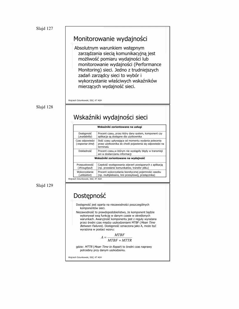
Slajd 127
Wojciech Dziunikowski, SSiZ, KT AGH
Monitorowanie wydajnościAbsolutnym warunkiem wstępnym
zarządzania siecią komunikacyjną jest możliwość pomiaru wydajności lub monitorowanie wydajności (Performance Monitoring) sieci. Jedno z trudniejszych zadań zarządcy sieci to wybór i wykorzystanie właściwych wskaźników mierzących wydajność sieci.
Slajd 128
Wojciech Dziunikowski, SSiZ, KT AGH
Wskaźniki wydajności sieci
Procent wykorzystania teoretycznej pojemności zasobu (np. multipleksera, linii przesyłowej, przełącznika)
Wykorzystanie(utilization)
Częstość występowania zdarzeń powiązanych z aplikacją (np. przesłanie komunikatów, transfer pliku)
Przepustowość(throughput)
Wskaźniki zorientowane na wydajność
Procent czasu,w którym nie wystąpiły błędy w transmisji ani w dostarczaniu informacji
Dokładność
Ilość czasu upływająca od momentu wydania polecenia przez użytkownika do chwili pojawienia się odpowiedzi na terminalu
Czas odpowiedzi(response time)
Procent czasu, przez który dany system, komponent czy aplikacja są dostępne dla użytkownika
Dostępność(availability)
Wskaźniki zorientowane na usługi
Slajd 129
Wojciech Dziunikowski, SSiZ, KT AGH
DostępnośćDostępność jest oparta na niezawodności poszczególnych
komponentów sieci. Niezawodność to prawdopodobieństwo, że komponent będzie
wykonywał swą funkcję w danym czasie w określonych warunkach. Awaryjność komponentu jest z reguły wyrażana przez średni czas między uszkodzeniami MTBF (Mean Time Between Failures). Dostępność oznaczona jako A, może być wyrażona w postaci wzoru:
MTTRMTBF
MTBFA
+
=
gdzie: MTTR (Mean Time to Repair) to średni czas naprawy potrzebny przy danym uszkodzeniu.
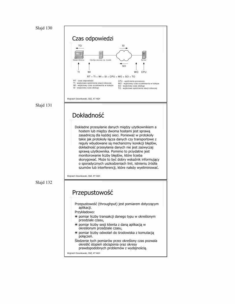
Slajd 130
Wojciech Dziunikowski, SSiZ, KT AGH
Czas odpowiedzi
Stacja robocza Interfejs sieciowy np. mostek Serwer
TO
TI WI
SI
SO
WO CPU
RT - czas odpowiedzi
TI - wejściowe opóźnienie stacji roboczej
WI - wejściowy czas oczekiwania w kolejce
SI - wejsciowy czas obsługi
RT = TI + WI + SI + CPU + WO + SO + TO
CPU - opóźnienie procesora
WO - wyjściowy czas oczekiwania w kolejce
SO - wyjściowy czas obsługi
TO - wyjściowe opóźnienie stacji roboczej
Slajd 131
Wojciech Dziunikowski, SSiZ, KT AGH
Dokładność
Dokładne przesyłanie danych między użytkownikiem a hostem lub między dwoma hostami jest sprawą zasadniczą dla każdej sieci. Ponieważ w protokoły takie jak protokoły łącza danych czy transportowe z reguły wbudowane są mechanizmy korekcji błędów, dokładność przesyłania danych nie jest zazwyczaj sprawą użytkownika. Pomimo to przydatne jest monitorowanie liczby błędów, które trzeba skorygować. Może to być dobry wskaźnik informujący o sporadycznych uszkodzeniach linii, istnieniu źródła szumów lub interferencji, które należy wyeliminować.
Slajd 132
Wojciech Dziunikowski, SSiZ, KT AGH
Przepustowość
Przepustowość (throughput) jest pomiarem dotyczącym aplikacji.
Przykładowo:pomiar liczby transakcji danego typu w określonym przedziale czasu,pomiar liczby sesji klienta z daną aplikacją w określonym przedziale czasu,pomiar liczby odwołań do środowiska z komutacją połączeń.
Śledzenie tych pomiarów przez określony czas pozwala określić stopień obciążenia oraz okresy prawdopodobnych problemów z wydajnością.
Slajd 133
Wojciech Dziunikowski, SSiZ, KT AGH
Wykorzystanie
Wykorzystanie (utilization) jest pomiarem dokładniejszym niż przepustowość. Odnosi się do określenia procentu czasu, w jakim dany zasób jest wykorzystywany w przeciągu określonego przedziału czasu.
Slajd 134
Wojciech Dziunikowski, SSiZ, KT AGH
Funkcja monitorowania wydajności
Monitorowanie wydajności obejmuje trzy składniki:Pomiar wydajności (Performance Measurement), czyli rzeczywistego gromadzenia statystyk o ruchu i czasach jego realizacji;Analizę wydajności, na którą składa się oprogramowanie do redukowania i prezentowania danychSztuczne wytwarzanie ruchu (Synthetic Traffic Generation), które pozwala na obserwowanie sieci przy kontrolowanym obciążeniu.
Slajd 135
Wojciech Dziunikowski, SSiZ, KT AGH
Typy pomiarów dokonywane w typowej sieci LAN
Macierz komunikacyjna hostaMacierz komunikacyjna grupyHistogram typów pakietówHistogram rozmiaru pakietów danychRozkład przepustowość-wykorzystanieHistogram czasu przesyłania pakietuOpóźnienie przejmowania kanałuHistogram opóźnień komunikacyjnychHistogram wystąpień kolizjiHistogram liczby transmisji
Slajd 136
Wojciech Dziunikowski, SSiZ, KT AGH
Monitorowanie uszkodzeń
Celem monitorowania uszkodzeń (Fault Monitoring) jest jak najszybsze wykrywanie ich wystąpienia oraz identyfikowanie przyczyn tych błędów, tak aby mogły być podjęte odpowiednie działania naprawcze.
W złożonym środowisku lokalizowanie i rozpoznawanie sytuacji awaryjnych może być trudne.
Slajd 137
Wojciech Dziunikowski, SSiZ, KT AGH
Problemy przy monitorowaniu uszkodzeń
Wymienia się następujące problemy specyficzne przy obserwowaniu uszkodzeń:uszkodzenia nieobserwowalne,uszkodzenia częściowo obserwowalne,niepewność obserwacji.
Slajd 138
Wojciech Dziunikowski, SSiZ, KT AGH
RMONNajważniejszym dodatkiem do podstawowego
zbioru standardów kryjących się pod wspólną nazwą SNMP (SMI, MIB, SNMP) jest specyfikacja zdalnego nadzoru sieci RMON.
RMON MIB został zdefiniowany w trzech etapach:Listopad 1991 - oryginalny RMON (RMON1) (RFC1271)Wrzesień 1993 - TokenRing (RFC1512)1995 - RFC1757Styczeń 1997 - definicja RMON2 (RFC2021)

Slajd 139
Wojciech Dziunikowski, SSiZ, KT AGH
RMONrmon (mib-2 16)
statistics (1)
history (2)
alarm (3)
host (4)
hostTopN (5)
matrix (6)
filter (7)
capture (8)
event (9) protocolDir (11)
protocolDist (12)
addressMap (13)
n1Host (14)
n1Matrix (15)
a1Host (16)
a1Matrix (17)
usrHistory (18)
probeConfig (19)
rmonConformance (20)
tokenRing (10)
Slajd 140
Wojciech Dziunikowski, SSiZ, KT AGH
RMON
Specyfikacja RMON to przede wszystkim definicja bazy MIB. Dokument RFC 1757 definiuje poza tym następujące dodatkowe zadania RMON przyświecające jego projektantom:działanie w trybie off-line (Off-line Operation),nadzór zapobiegawczy (Proactive Monitoring),wykrywanie i raportowanie problemów (Problem Detection and Reporting),udostępnianie informacji dodatkowych (Value-Added Data),współpraca z wieloma zarządcami (Multiple Managers)
Slajd 141
Wojciech Dziunikowski, SSiZ, KT AGH
Funkcje RMON
Monitorowana sieć
Gromadzenie danych
Stat. TR Historia TR Ster. historią
Stat. Eth Historia Eth Ster. historią
Stat. Host Stat. HostTopN
Stat. macierzowe
Filtr. pakiet. Filtr. kanał. Podgl. pakiet
Generacja alarmów
Generacja zdarzeń
Zarządca
Statystyki Token Ring
Statystyki Ethernet
Statystyki hosta oraz połączeń
Grupa filtrująca
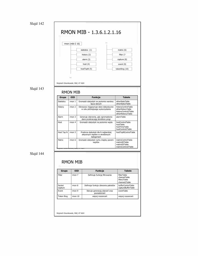
Slajd 142
Wojciech Dziunikowski, SSiZ, KT AGH
RMON MIB - 1.3.6.1.2.1.16
rmon (mib-2 16)
statistics (1)
history (2)
alarm (3)
host (4)
hostTopN (5)
matrix (6)
filter (7
capture (8)
...
...
event (9)
tokenRing (10)
Slajd 143
Wojciech Dziunikowski, SSiZ, KT AGH
RMON MIB
matrixControlTablematrixSDTablematrixDSTablematrixControl2Table
Gromadzi statystyki ruchu między parami węzłów
rmon 6Matrix
hostTopNControlTablePrzelicza statystyki dla N najbardziej aktywnych węzłów w określonych
kategoriach
rmon 5Host Top N
hostControlTablehostTablehostTimeTablehostControl2Table
Gromadzi statystyki na poziomie węzłarmon 4Host
alarmTableGeneruje zdarzenia, gdy zgromadzone dane przekraczają określone progi
rmon 3Alarm
historyControlTableetherHistoryTablehistoryControl2TableetherHistory2Table
Okresowo magazynuje dane statystyczne w celu późniejszego wykorzystania
rmon 2History
etherStatsTableetherStats2Table
Gromadzi statystyki na poziomie warstwy łącza danych
rmon 1Statistics
TabeleFunkcjaOIDGrupa
Slajd 144
Wojciech Dziunikowski, SSiZ, KT AGH
RMON MIB
eventTableSteruje generacją zdarzeń oraz powiadomień
rmon 9Event
filterTablechannelTablefilter2Tablechannel2Table
Definiuje funkcję filtrowaniarmon 7Filter
bufferControlTablecaptureBufferTable
Definiuje funkcje zbierania pakietówrmon 8Packet Capture
więcej rozszerzeńwięcej rozszerzeńrmon 10Token Ring
TabeleFunkcjaOIDGrupa
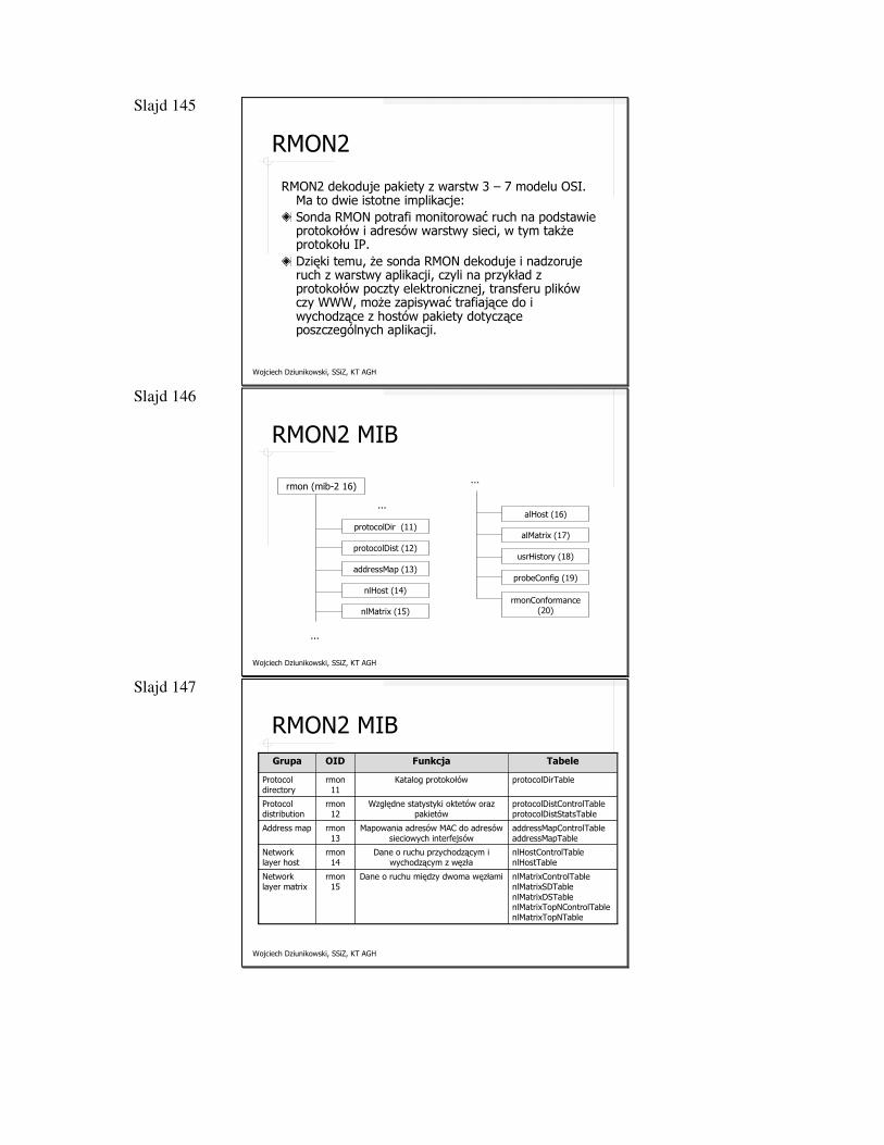
Slajd 145
Wojciech Dziunikowski, SSiZ, KT AGH
RMON2
RMON2 dekoduje pakiety z warstw 3 – 7 modelu OSI. Ma to dwie istotne implikacje:Sonda RMON potrafi monitorować ruch na podstawie protokołów i adresów warstwy sieci, w tym także protokołu IP. Dzięki temu, że sonda RMON dekoduje i nadzoruje ruch z warstwy aplikacji, czyli na przykład z protokołów poczty elektronicznej, transferu plików czy WWW, może zapisywać trafiające do i wychodzące z hostów pakiety dotyczące poszczególnych aplikacji.
Slajd 146
Wojciech Dziunikowski, SSiZ, KT AGH
RMON2 MIB
rmon (mib-2 16)
protocolDir (11)
protocolDist (12)
addressMap (13)
nlHost (14)
nlMatrix (15)
alHost (16)
alMatrix (17)
usrHistory (18)
...
...
probeConfig (19)
...
rmonConformance(20)
Slajd 147
Wojciech Dziunikowski, SSiZ, KT AGH
RMON2 MIB
nlMatrixControlTablenlMatrixSDTablenlMatrixDSTablenlMatrixTopNControlTablenlMatrixTopNTable
Dane o ruchu między dwoma węzłamirmon15
Network layer matrix
nlHostControlTablenlHostTable
Dane o ruchu przychodzącym i wychodzącym z węzła
rmon14
Network layer host
addressMapControlTableaddressMapTable
Mapowania adresów MAC do adresów sieciowych interfejsów
rmon13
Address map
protocolDistControlTableprotocolDistStatsTable
Względne statystyki oktetów oraz pakietów
rmon12
Protocol distribution
protocolDirTableKatalog protokołówrmon 11
Protocol directory
TabeleFunkcjaOIDGrupa
Slajd 148
Wojciech Dziunikowski, SSiZ, KT AGH
RMON2 MIB
RMON2 MIB compliances and compliance groups
rmon20
RMON conformance
serialConfigTablenetConfigTabletrapDestTableserialConnectionTable
Dane konfiguracyjne sondyrmon19
Probe configuration
usrHistoryControlTableusrHistoryObjectTable
Zapisuje okresowo dane określone przez użytkownika w historii
rmon18
User history collection
alMatrixControlTablealMatrixSDTablealMatrixDSTablealMatrixTopNControlTablealMatrixTopNTable
Dane o ruchu według protokołu między dwoma węzłami
rmon17
Application layer matrix
alHostControlTablealHostTable
Dane o ruchu przychodzącym i wychodzącym według protokołu z węzła
rmon 16
Application layer host
TabeleFunkcjaOIDGrupa
Slajd 149
Wojciech Dziunikowski, SSiZ, KT AGH
NetFlow
Rozwiązanie wprowadzone przez firmę CiscoUmożliwia uzyskanie informacji o przepływach (flow) dla wybranego ruteraInformacje dostępne w wersji 1� adres IP hosta źródłowego, adres IP hosta docelowego� port źródłowy, port docelowy� adres kolejnego rutera� numer interfejsu wejściowego, numer interfejsu wyjściowego� liczba przesłanych pakietów, liczba przesłanych bajtów� wartość pola sysUpTime, w momencie rozpoczęcia połączenia oraz
w momencie zakończenia połączenia� pole IP protocol number, pole ToS� logiczny OR wszystkich przesłanych flag protokołu TCP
Slajd 150
Wojciech Dziunikowski, SSiZ, KT AGH
NetFlow
Dostępne są również kolejne wersje� wersja 5 – uzyskiwanie informacji o systemach
autonomicznych na podstawie protokołu BGP� wersja 7 – dostępna tylko w Cisco Catalyst 5000� wersja 8 – wprowadzenie mechanizmu
agregującego przepływy, zmniejszenie ilości informacji wysyłanej z rutera
� wersja 9 – wprowadzenie szablonów dla raportów, na podstawie tej wersji NetFlow opracowywany jest standard IETF IPFIX