Wacław Tomaszewski, Investigation of Electrospinning with ... · Wacław Tomaszewski, Marek...
5
FIBRES & TEXTILES in Eastern Europe October / December 2005, Vol. 13, No. 4 (52) 22 Wacław Tomaszewski, Marek Szadkowski Institute of Chemical Fibres ul. M.Skłodowskiej-Curie 19/27, 90-570 Łódź, Poland e-mail: [email protected] Abstract Three types of multi-jet electrospinning heads, series, elliptic and concentric, were constructed in compact forms. Their usefulness for electrospinning was tested with the use of poly(vinyl alcohol) (PVA) water solution as the spinning liquid. The efficiency of the manufacture of nanofibrous mats was controlled by standard weighting procedure. The thickness of nanofibres and the morphology of the mats were investigated with a scanning electron microscope. The concentric electrospinning head was selected as the best type with respect to both the efficiency and quality of the process. It can produce 1 mg of dry PVA nanofibres from one spinning pipe during one minute. Additionally, the utility of the electrospinning stage with a rotating tube as a collecting electrode and equipped with a concentric electrospinning head was examined. Key words: electrospinning, multi-jet electrospinning, nanofibres, nanofibrous mat. Investigation of Electrospinning with the Use of a Multi-jet Electrospinning Head n Introduction The well-known beneficial influence of thinner fibres on many nonwoven prop- erties is one of the most important causes for worldwide interest in the use of elec- trospinning as a method for creating this kind of material. This technique enables fibres to be manufactured with diameters covering almost the whole nanometer scale, and they can be made from both synthetic and natural polymers [1]. Poly- mer nanofibres have an especially high surface-to-volume ratio [2-6], flexibility in surface functionalities and superior mechanical performance. They have a broad range of applications [1], in par- ticular in tissue engineering [7], sensors [8], protective clothing [9], filters [10], etc. The use of electrostatic force as a process for producing polymer filaments was patented by Formhals [11-13] in 1934. In this process, a high voltage is used to create an electrically charged jet of polymer solution or melt, which dries or solidifies, during travel between electrodes, to leave a polymer fibre. In practice, it is rather the rule that the pi- pette or the spinning head which contains the polymer solution/melt is connected to high voltage, and the collector is ground- ed. This induces a charge on the surface of the liquid. The surface of the liquid at the end of pipette is shaped by surface tension, viscosity and both electrostatic and gravitational fields. Mutual charge repulsion causes a force, which elongates the beginning hemispherical surface or the drop of the liquid, to form a conical shape known as the Taylor cone [14]. At a sufficiently high voltage between the electrodes, the repulsive electrostatic force overcomes the surface tension, and the charged jet of the fluid is ejected from the tip of the Taylor cone. Further inter- action between the charged surface of liquid stream and the electric field causes the jet to become very thin. Simultane- ously the surface-to-volume ratio of the jet grows quickly, and leads(by solvent evaporation or the falling temperature of the melt) to solidification in the form of a fibre. These fibres are usually collected on a flat metal screen or on the surface of a rotating roller as the result of a random process which creates the layer of non- woven material. In certain cases, freshly obtained fibres can require additional processing such as drying or coagulation. In general, electrospinning can manufac- ture fibres which are not only very thin, but also have a smooth lateral surface and a uniform profile. Unfortunately the efficiency of this method is not high. In most published works devoted to inves- tigating electrospinning, the authors have used experimental stages equipped with only a single spinning point. Only Ding et al. [15] used a few syringes simultane- ously for electrospinning from different polymer solutions, and Schiffman et al. [16] applied a system of a 24-gauge nee- dle to electrospin PLA solution into mats. Our present knowledge about the pos- sibilities of using multi-jet systems for electrospinning, and especially about the relationship between the configuration HV A B HV 4 5 3 2 1 8 7 6 6 9 9 4 Figure 1. Plan of the electrospinning variants based on a set-up stand im- movable during spinning, marked as A, and on a movable stand with a rotating tube, marked as B; additionally marked: 1 – electrospinning multi-jet head; 2 – set-up stand; 3 – movable stand; 4 – aluminium foil; 5 – rotating tube; 6 – high-voltage power supply; 7 – peristaltic pump; 8 – U-pipe water ma- nometer; 9 - ground; the arrows indi- cate the ability to: ↔- adjustment of the electro-spin- ning multi jet heat; ↔ - movement dur- ing spinning.
Transcript of Wacław Tomaszewski, Investigation of Electrospinning with ... · Wacław Tomaszewski, Marek...
FIBRES & TEXTILES in Eastern Europe October / December 2005, Vol. 13, No. 4 (52)22 23FIBRES & TEXTILES in Eastern Europe October / December 2005, Vol. 13, No. 4 (52)
Wacław Tomaszewski, Marek Szadkowski
Institute of Chemical Fibresul. M.Skłodowskiej-Curie 19/27,
90-570 Łódź, Poland e-mail: [email protected]
AbstractThree types of multi-jet electrospinning heads, series, elliptic and concentric, were constructed in compact forms. Their usefulness for electrospinning was tested with the use of poly(vinyl alcohol) (PVA) water solution as the spinning liquid. The efficiency of the manufacture of nanofibrous mats was controlled by standard weighting procedure. The thickness of nanofibres and the morphology of the mats were investigated with a scanning electron microscope. The concentric electrospinning head was selected as the best type with respect to both the efficiency and quality of the process. It can produce 1 mg of dry PVA nanofibres from one spinning pipe during one minute. Additionally, the utility of the electrospinning stage with a rotating tube as a collecting electrode and equipped with a concentric electrospinning head was examined.
Key words: electrospinning, multi-jet electrospinning, nanofibres, nanofibrous mat.
Investigation of Electrospinning with the Use of a Multi-jet Electrospinning Head
n IntroductionThe well-known beneficial influence of thinner fibres on many nonwoven prop-erties is one of the most important causes for worldwide interest in the use of elec-trospinning as a method for creating this kind of material. This technique enables fibres to be manufactured with diameters covering almost the whole nanometer scale, and they can be made from both synthetic and natural polymers [1]. Poly-mer nanofibres have an especially high surface-to-volume ratio [2-6], flexibility in surface functionalities and superior mechanical performance. They have a broad range of applications [1], in par-ticular in tissue engineering [7], sensors [8], protective clothing [9], filters [10], etc. The use of electrostatic force as a process for producing polymer filaments was patented by Formhals [11-13] in 1934. In this process, a high voltage is used to create an electrically charged jet of polymer solution or melt, which dries or solidifies, during travel between electrodes, to leave a polymer fibre. In practice, it is rather the rule that the pi-pette or the spinning head which contains the polymer solution/melt is connected to high voltage, and the collector is ground-ed. This induces a charge on the surface of the liquid. The surface of the liquid at
the end of pipette is shaped by surface tension, viscosity and both electrostatic and gravitational fields. Mutual charge repulsion causes a force, which elongates the beginning hemispherical surface or the drop of the liquid, to form a conical shape known as the Taylor cone [14]. At a sufficiently high voltage between the electrodes, the repulsive electrostatic force overcomes the surface tension, and the charged jet of the fluid is ejected from the tip of the Taylor cone. Further inter-action between the charged surface of liquid stream and the electric field causes the jet to become very thin. Simultane-ously the surface-to-volume ratio of the jet grows quickly, and leads(by solvent evaporation or the falling temperature of the melt) to solidification in the form of a fibre. These fibres are usually collected on a flat metal screen or on the surface of a rotating roller as the result of a random
process which creates the layer of non-woven material. In certain cases, freshly obtained fibres can require additional processing such as drying or coagulation. In general, electrospinning can manufac-ture fibres which are not only very thin, but also have a smooth lateral surface and a uniform profile. Unfortunately the efficiency of this method is not high. In most published works devoted to inves-tigating electrospinning, the authors have used experimental stages equipped with only a single spinning point. Only Ding et al. [15] used a few syringes simultane-ously for electrospinning from different polymer solutions, and Schiffman et al. [16] applied a system of a 24-gauge nee-dle to electrospin PLA solution into mats. Our present knowledge about the pos-sibilities of using multi-jet systems for electrospinning, and especially about the relationship between the configuration
HV
A B
HV
4
5
32
1
8 7
6 6
9 9
4
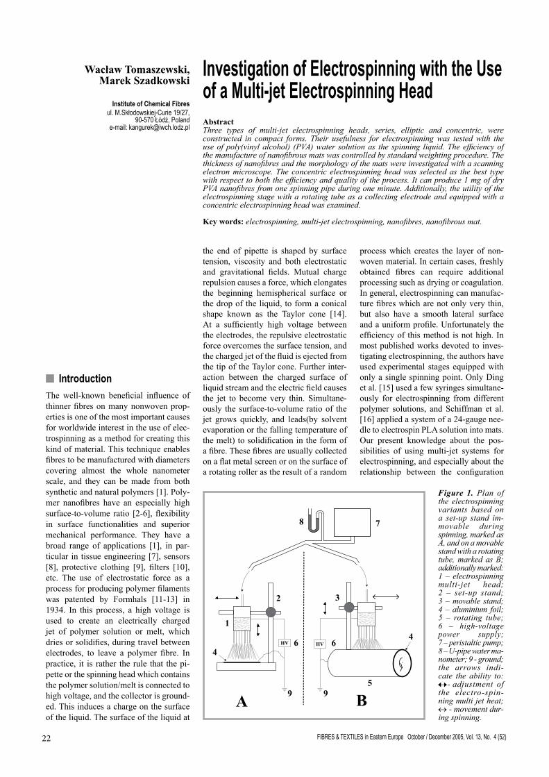
Figure 1. Plan of the electrospinning variants based on a set-up stand im-movable during spinning, marked as A, and on a movable stand with a rotating tube, marked as B;additionally marked: 1 – electrospinning multi-jet head; 2 – set-up stand; 3 – movable stand; 4 – aluminium foil; 5 – rotating tube; 6 – high-voltage power supply; 7 – peristaltic pump; 8 – U-pipe water ma-nometer; 9 - ground; the arrows indi-cate the ability to: ↔- adjustment of the electro-spin-ning multi jet heat;↔ - movement dur-ing spinning.
FIBRES & TEXTILES in Eastern Europe October / December 2005, Vol. 13, No. 4 (52)22 23FIBRES & TEXTILES in Eastern Europe October / December 2005, Vol. 13, No. 4 (52)
of spinning points and the efficiency or quality of this kind of spinning, is scarce. This awoke our interest in making an ef-fort to construct and test a special electro-spinning head equipped with more than one spinning point. To test this device, we decided to use a water solution of PVA, which is easy both to prepare and to electrospin.
n ExperimentalPreparation and properties of the spinning solutionA 15 wt% PVA (Mn 72,000) (Chemia–Łódź S.A.) solution was prepared from PVA powder and distilled cold water with moderate stirring, heated up to 40°C and stirring until visible particles disap-peared; it was then sealed in a hermetic jar and stabilised at 90°C for 2 h. The vis-cosity was determined by measuring the melt flow index, which was 600 g/10 min at 20°C. The PVA solution’s electrical resistance was measured by a standard digital multimeter after previously filling a polyethylene pipe with this solution. The pipe had an inner diameter of 3 mm and a length of 0.5 m, and both its ends were stopped by metal electrodes. The electric resistivity of the PVA solution as measured in this system was within the range of 2.9 to 3.6 Ωm.
Experimental stand for electrospinningAll electrospinning experiments were carried out in laboratory scale, and under standard environmental conditions: the temperature of both the surroundings and the spinning liquid ranged within 20 – 22oC, and the relative humidity was about 65%.We used two different variants of the stand for electrospinning,
shown schematically in Figure 1, and marked as A and B.
Variant A: the system based on the set-up stand (2) made of electrically insulat-ing materials, and immovable during work. The stand (2) is supported on a plastic table and has a vertically movable arm for the attachment of the spinning head (1). The electrically grounded sheet of aluminium foil (4) placed on the table played the role of the collecting elec-trode. The spinning head is connected to high voltage, which was typically 20 kV The ES50P-20W voltage supply from Ormond Beach, USA was used.. In most cases, the distance between the bottom of the spinning head and the aluminium col-lecting electrode was 20 cm. The system is equipped with a small peristaltic pump (7), which creates air pressure to crowd the spinning liquid from the spinning head. The pressure was controlled by a U-pipe manometer (8) with water, and did not exceed 4 cm H2O.
Variant B: the system based on a grounded rotating aluminium tube (5), which was covered with a sheet of thin aluminium foil (4) as a collecting elec-trode. The spinning head (1) was clamped to a stand (3), which can be moved along the track at a fixed distance above the rotating tube. The rotating velocity was usually 10 rpm, and the spinning head was shifted 2 cm/min longitudinal to the axis of the rotating tube (5). The rest of the equipment was the same as for vari-ant A.
Types of compact multi-jet electros-pinning headThree different multi-jet electrospinning heads, named as series, elliptic, and concentric, and shown in Figure 2, were constructed and tested. Each of them consisted of a container for the spinning liquid with a volume of about 100 cm3,
and a system of between 10 to 26 steel pipes with diameters of 0.8 mm installed in the bottom of the container with spaces of 0.3 cm to 1.5 cm between them. Due to both the number of pipes and the small distance between them, we named this type of electrospinning heads as compact multi-jet heads.
Characterisation techniquesThe morphology and diameter of nanofi-brous mats were determined by scanning electron microscopy (Quanta 200, FEI Co., USA). The diameters of the nanofi-bres were determined by using (Docu, Soft Imaging System) software. The efficiency of electrospinning was deter-mined as the weight of the nanofibrous mat in relation to the time of the proc-ess and number of the active pipes. The weighting of nanofibrous mats was car-ried out on a laboratory mechanical bal-ance, and was calculated after subtracting the mass of the aluminium foil. Certain of the visible effects of the electrospin-ning process and the shape and facture of the nanofibrous mats were registered by a simple electronic camera.
n Results and discussionTesting rhe electrospinning headsDuring testing, the linear electrospin-ning head worked in a completely wrong manner. Only a few border pipes on both sides formed fibres, while the rest of them located nearer the centre were quite inactive. This system of spinning led to a much lower efficiency than ex-pected. Additionally, the inactive pipes generated only gravitationally deformed drops of spinning liquid instead of fibres. The results of this test, in the form of photographs of the characteristic traces made by electrospinning on the collect-ing electrode over time intervals of a few minutes, are shown in Figure 3.
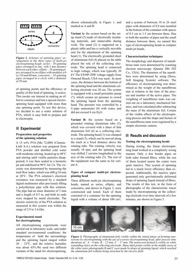
Figure 2. Schemes of spinning pipes’ ar-rangement in the three types of multi-jet electrospinning heads: series – 26 spinning pipes arranged in line, with 3 mm distance between each other; elliptic – 26 spinning pi-pes arranged in an ellipse with modulus a/b as 110 mm/60 mm; concentric – 10 spinning pipes arranged in a circle with a diameter of 50 mm.
Figure 3. Photographs of aluminium foils visible within the initial phase of forming non-wovens by electrospinning with the use of a series electrospinning head, after process time durations of : A – 4 min; B – 12 min; C – 17 min. The nonwoven formed is visible as white expanding stairs on the collecting electrode. Many dark points visible in the middle areas of the white stairs photographs B and C were made by drops of spinning liquid, which reached the aluminium foil without being stretched by the electric field.
FIBRES & TEXTILES in Eastern Europe October / December 2005, Vol. 13, No. 4 (52)24 25FIBRES & TEXTILES in Eastern Europe October / December 2005, Vol. 13, No. 4 (52)
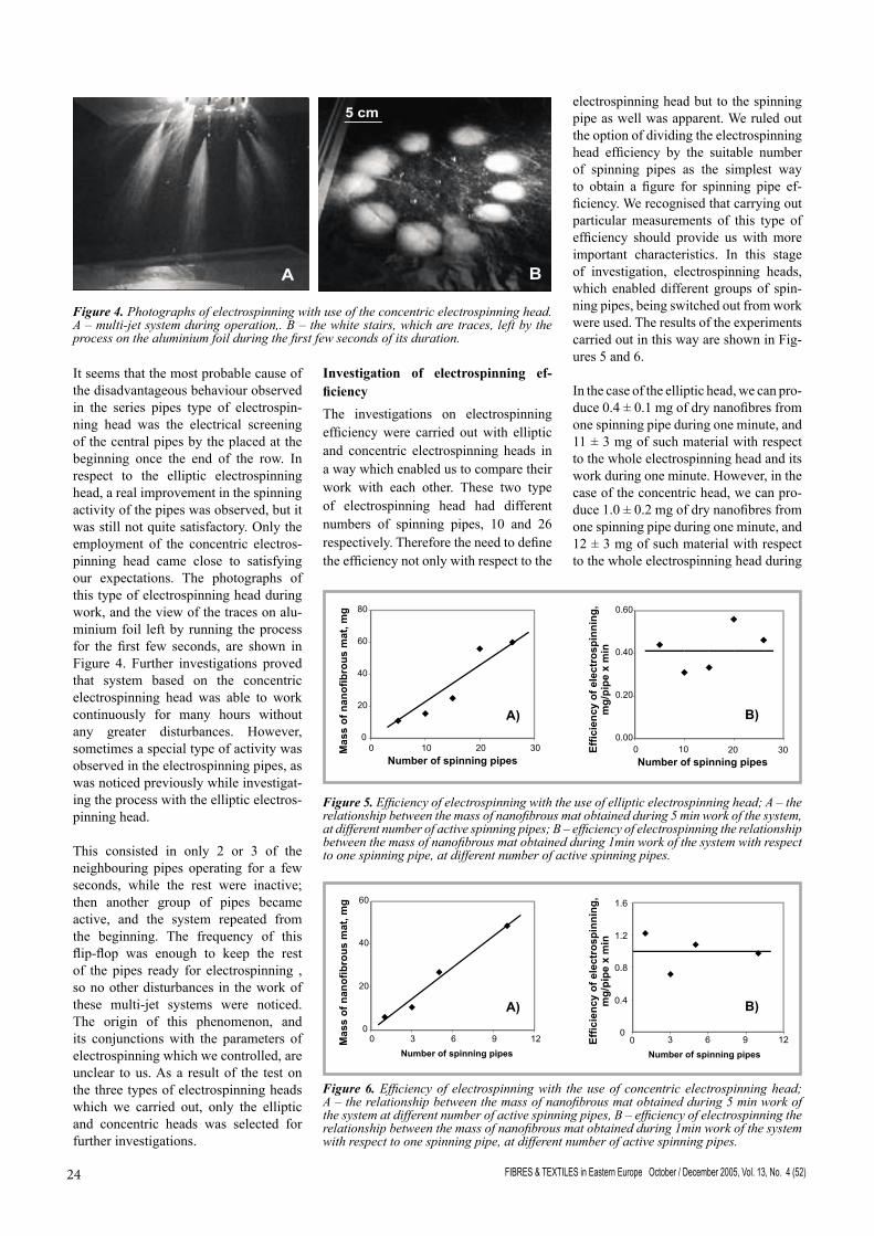
It seems that the most probable cause of the disadvantageous behaviour observed in the series pipes type of electrospin-ning head was the electrical screening of the central pipes by the placed at the beginning once the end of the row. In respect to the elliptic electrospinning head, a real improvement in the spinning activity of the pipes was observed, but it was still not quite satisfactory. Only the employment of the concentric electros-pinning head came close to satisfying our expectations. The photographs of this type of electrospinning head during work, and the view of the traces on alu-minium foil left by running the process for the first few seconds, are shown in Figure 4. Further investigations proved that system based on the concentric electrospinning head was able to work continuously for many hours without any greater disturbances. However, sometimes a special type of activity was observed in the electrospinning pipes, as was noticed previously while investigat-ing the process with the elliptic electros-pinning head.
This consisted in only 2 or 3 of the neighbouring pipes operating for a few seconds, while the rest were inactive; then another group of pipes became active, and the system repeated from the beginning. The frequency of this flip-flop was enough to keep the rest of the pipes ready for electrospinning , so no other disturbances in the work of these multi-jet systems were noticed. The origin of this phenomenon, and its conjunctions with the parameters of electrospinning which we controlled, are unclear to us. As a result of the test on the three types of electrospinning heads which we carried out, only the elliptic and concentric heads was selected for further investigations.
Figure 4. Photographs of electrospinning with use of the concentric electrospinning head. A – multi-jet system during operation,. B – the white stairs, which are traces, left by the process on the aluminium foil during the first few seconds of its duration.
Investigation of electrospinning ef-ficiencyThe investigations on electrospinning efficiency were carried out with elliptic and concentric electrospinning heads in a way which enabled us to compare their work with each other. These two type of electrospinning head had different numbers of spinning pipes, 10 and 26 respectively. Therefore the need to define the efficiency not only with respect to the
electrospinning head but to the spinning pipe as well was apparent. We ruled out the option of dividing the electrospinning head efficiency by the suitable number of spinning pipes as the simplest way to obtain a figure for spinning pipe ef-ficiency. We recognised that carrying out particular measurements of this type of efficiency should provide us with more important characteristics. In this stage of investigation, electrospinning heads, which enabled different groups of spin-ning pipes, being switched out from work were used. The results of the experiments carried out in this way are shown in Fig-ures 5 and 6.
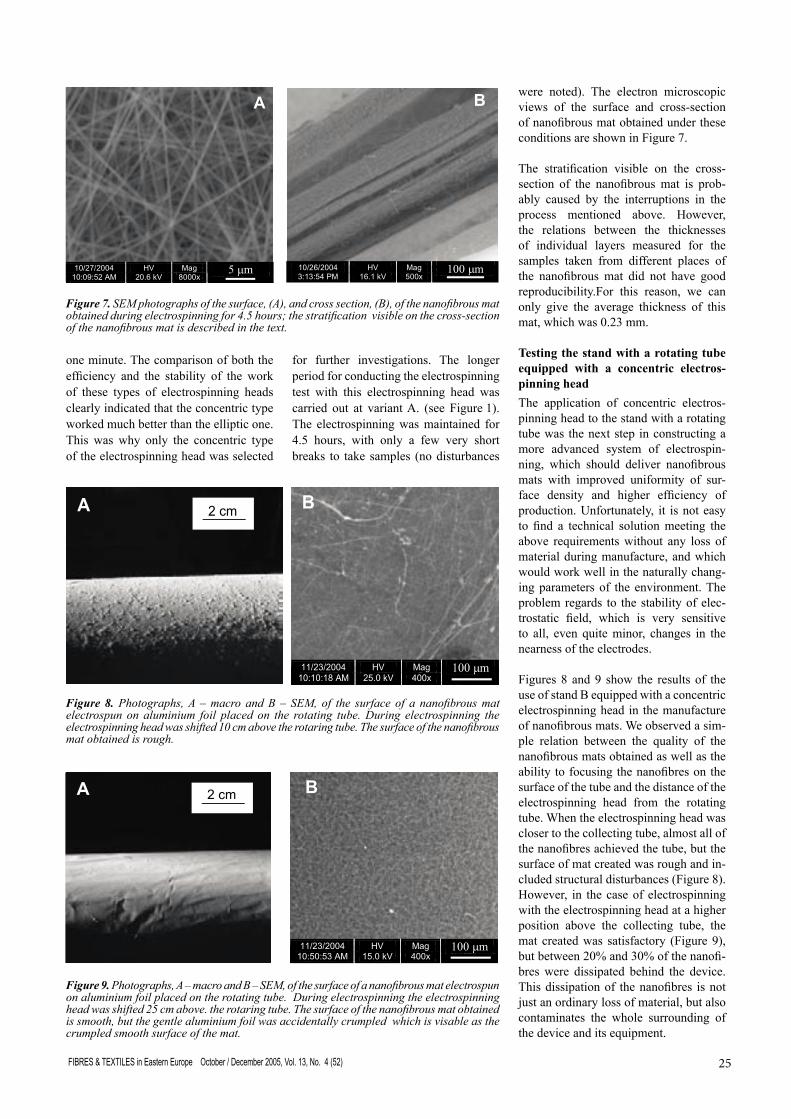
In the case of the elliptic head, we can pro-duce 0.4 ± 0.1 mg of dry nanofibres from one spinning pipe during one minute, and 11 ± 3 mg of such material with respect to the whole electrospinning head and its work during one minute. However, in the case of the concentric head, we can pro-duce 1.0 ± 0.2 mg of dry nanofibres from one spinning pipe during one minute, and 12 ± 3 mg of such material with respect to the whole electrospinning head during
Figure 6. Efficiency of electrospinning with the use of concentric electrospinning head; A – the relationship between the mass of nanofibrous mat obtained during 5 min work of the system at different number of active spinning pipes, B – efficiency of electrospinning the relationship between the mass of nanofibrous mat obtained during 1min work of the system with respect to one spinning pipe, at different number of active spinning pipes.
Figure 5. Efficiency of electrospinning with the use of elliptic electrospinning head; A – the relationship between the mass of nanofibrous mat obtained during 5 min work of the system, at different number of active spinning pipes; B – efficiency of electrospinning the relationship between the mass of nanofibrous mat obtained during 1min work of the system with respect to one spinning pipe, at different number of active spinning pipes.
A) B)
A) B)
FIBRES & TEXTILES in Eastern Europe October / December 2005, Vol. 13, No. 4 (52)24 25FIBRES & TEXTILES in Eastern Europe October / December 2005, Vol. 13, No. 4 (52)
one minute. The comparison of both the efficiency and the stability of the work of these types of electrospinning heads clearly indicated that the concentric type worked much better than the elliptic one. This was why only the concentric type of the electrospinning head was selected
for further investigations. The longer period for conducting the electrospinning test with this electrospinning head was carried out at variant A. (see Figure 1). The electrospinning was maintained for 4.5 hours, with only a few very short breaks to take samples (no disturbances
were noted). The electron microscopic views of the surface and cross-section of nanofibrous mat obtained under these conditions are shown in Figure 7.
The stratification visible on the cross-section of the nanofibrous mat is prob-ably caused by the interruptions in the process mentioned above. However, the relations between the thicknesses of individual layers measured for the samples taken from different places of the nanofibrous mat did not have good reproducibility.For this reason, we can only give the average thickness of this mat, which was 0.23 mm.
Testing the stand with a rotating tube equipped with a concentric electros-pinning headThe application of concentric electros-pinning head to the stand with a rotating tube was the next step in constructing a more advanced system of electrospin-ning, which should deliver nanofibrous mats with improved uniformity of sur-face density and higher efficiency of production. Unfortunately, it is not easy to find a technical solution meeting the above requirements without any loss of material during manufacture, and which would work well in the naturally chang-ing parameters of the environment. The problem regards to the stability of elec-trostatic field, which is very sensitive to all, even quite minor, changes in the nearness of the electrodes.
Figures 8 and 9 show the results of the use of stand B equipped with a concentric electrospinning head in the manufacture of nanofibrous mats. We observed a sim-ple relation between the quality of the nanofibrous mats obtained as well as the ability to focusing the nanofibres on the surface of the tube and the distance of the electrospinning head from the rotating tube. When the electrospinning head was closer to the collecting tube, almost all of the nanofibres achieved the tube, but the surface of mat created was rough and in-cluded structural disturbances (Figure 8). However, in the case of electrospinning with the electrospinning head at a higher position above the collecting tube, the mat created was satisfactory (Figure 9), but between 20% and 30% of the nanofi-bres were dissipated behind the device. This dissipation of the nanofibres is not just an ordinary loss of material, but also contaminates the whole surrounding of the device and its equipment.
Figure 7. SEM photographs of the surface, (A), and cross section, (B), of the nanofibrous mat obtained during electrospinning for 4.5 hours; the stratification visible on the cross-section of the nanofibrous mat is described in the text.
Figure 9. Photographs, A – macro and B – SEM, of the surface of a nanofibrous mat electrospun on aluminium foil placed on the rotating tube. During electrospinning the electrospinning head was shifted 25 cm above. the rotaring tube. The surface of the nanofibrous mat obtained is smooth, but the gentle aluminium foil was accidentally crumpled which is visable as the crumpled smooth surface of the mat.
Figure 8. Photographs, A – macro and B – SEM, of the surface of a nanofibrous mat electrospun on aluminium foil placed on the rotating tube. During electrospinning the electrospinning head was shifted 10 cm above the rotaring tube. The surface of the nanofibrous mat obtained is rough.
FIBRES & TEXTILES in Eastern Europe October / December 2005, Vol. 13, No. 4 (52)26
Received 02.06.2005 Reviewed 13.10.2005
n Conclusions The electrospinning testing carried out with three types of electrospinning heads, series, elliptic and concentric, proved that the latter two allowed the process to proceed on the basis of compact multi-jet systems using 10 or more spinning pipes. The concentric electrospinning head, which turned out best with regard to both the efficiency and the quality of the proc-ess, can produce 1 mg of dry PVA nanofi-bres from one spinning pipe during 1 min. This type of electrospinning head was examined over a longer duration of proc-ess (4.5 hours) without any disturbances. The trial with the electrospinning stand based on a rotating tube as a collection electrode and equipped with concentric electrospinning head, allowed the manu-facture of a satisfactory quality of nanofi-brous mat, but with a dissipation of about 20% of spun material behind the tube.
References 1. Huang Zheng-Ming, Zhang Y.-Z., Kotaki
M., Ramakrishna S., Composites Science and Technology (2003); 63: 2223-2253
2. Reneker D.H., Chun I.. Nanotechnology (1996); 7: 216-23.
3. Deitzel J. M., Kleinmeyer J., Harris D., Beck T.N.C., Polymer (2001); 42: 261-72.
4. Shin Y. M., Hohman M. M., Brenner M. P., Rutledge G. C., Polymer (2001); 42: 9955-67.
5. Reneker D. H., Yarin A. L., Fong H, Koombhongse S. J,. Appl Phys (2000); 87: 4531-47.
6. Yarin A. L., Koombhongse S., Reneker D. H., J Appl Phys (2001); 89: 3018-26.
7. Matthews J. A., Wnek G. E., Simpson D. G., Bowlin G. L., Biomacromolecules (2002); 3: 232-8.
8. Wang X. Y., Drew C., Lee S. H., Senecal K. J., Kumar J., Samuelson L. A., Nano-letters (2002); 2: 1273-5.
9. Schreuder-Gibson H. L., Gibson P., Sene-cal K., Sennett M., Walker J., Yeomans W. et al., J. Adv. Mater. (2002); 34: 44-55.
10. Tsaia P.P., Schreuder-Gibson H., Gibson P., J, Electrostat. (2002); 54: 333-41.
11. Formhals A. US patent 1,975,504, 1934.12. Formhals A. US patent 2,160,962, 1939.13. Formhals A. US patent 2,187,306, 1940.14. Taylor G.I.. Proc. Roy. Soc. London,
(1969); A313: 453-75.15. Ding B., Kimura E., Sato T., Fujita S.,
Shiratori S., Polymer (2004); 45: 1895-1900
16. Schiffman J.D., and Frey M., Cornell Polymer Outreach Program, Poster Session, May 24, 2004, Available from: http://www.popsymposium.cornell.edu/careinfo/.