VIRTUAL MODELS OF A NEW VERSION OF A LOADING TRANSPORTER UNIT
6
Krzysztof ZEMBROWSKI, Marek DANIELAK, Paweł STOBNICKI, „Journal of Research and Applications in Agricultural Engineering” 2015, Vol. 60(1) Aleksander RAKOWICZ, Sylwester WEYMANN 116 Krzysztof ZEMBROWSKI, Marek DANIELAK, Paweł STOBNICKI, Aleksander RAKOWICZ, Sylwester WEYMANN Industrial Institute of Agricultural Engineering ul. Starołęcka 31, 60-963 Poznań, Poland e-mail: [email protected] VIRTUAL MODELS OF A NEW VERSION OF A LOADING TRANSPORTER UNIT IN A TRACKED VEHICLE - KINETOSTATIC AND STRENGTH ANALYSIS Summary The article presents a new version of a modified loading transporter unit in a specialized tracked vehicle, made as part of the development project no. WND-POIG.01.03.01-00-164/09: “An integrated technology for the protection of wetlands against succession of vegetation causing a degradation of the natural environment” associated with the removal of unwanted vegetation from protected areas, particularly from National Parks and Natura 2000 areas. The design of a new loading transporter unit developed by the Department of Power Engineering and Dynamics of Agricultural Machines of PIMR in Poznań, was intended to improve the structural strength, as well as modify and simplify the previous design. A virtual model of the loading transporter unit was created, strength and kinetostatic analyses were performed with the use of SolidWorks 2014 software. In addition, the paper includes information on the original structural solution and presents a new, modified version of the loading transporter unit, adapted and tested in real-life field trials of the loading transporter unit of the tracked vehicle. Key words: loading transporter unit, tracked vehicle, kinetostatic analysis, strength analysis MODELE WIRTUALNE NOWEJ WERSJI WYSIĘGNIKA ROBOCZEGO POJAZDU GĄSIENICOWEGO – ANALIZA KINETOSTATYCZNA I WYTRZYMAŁOŚCIOWA Streszczenie W artykule przedstawiono nową wersję zmodyfikowanego wysięgnika roboczego specjalizowanego pojazdu gąsienicowego, realizowaną w ramach projektu rozwojowego nr WND-POIG.01.03.01-00-164/09 pt.: „Zintegrowana technologia ochrony obszarów wodno-błotnych przed sukcesją roślinności powodującej degradację środowiska przyrodniczego” związanego z usuwaniem niepożądanej roślinności z chronionych terenów zwłaszcza parków narodowych, parków krajobrazowych oraz obszarów Natura 2000. Projekt nowego wysięgnika opracowany przez Zespół ds. Energetyki i Dynamiki Maszyn Rolniczych PIMR w Poznaniu miał za zadanie poprawę wytrzymałości konstrukcyjnej, zmodyfikowanie i uproszczenie poprzedniej jego konstrukcji. Wykonano model wirtualny wysięgnika roboczego, przeprowadzono analizę wytrzymałościową oraz kinetostatyczną przy użyciu oprogramowania SolidWorks 2014. Ponadto w artykule zawarto informacje dotyczące pierwotnego rozwiązania konstrukcyjnego i przedstawiono nową, zmodyfikowaną wersję wysięgnika, którą zaadaptowano i sprawdzono podczas rzeczywistych prób terenowych modułu roboczego pojazdu gąsienicowego. Słowa kluczowe: wysięgnik roboczy, pojazd gąsienicowy, analiza kinetostatyczna, analiza wytrzymałościowa 1. Introduction The virtual model of a new version of the loading transporter unit of the tracked vehicle was developed as part of project no. WND-POIG.01.03.01-00-164/09 [1] pursued at the Industrial Institute of Agricultural Engineering (PIMR) in Poznań, by the Department of Power Engineering and Dynamics of Agricultural Machines. The key objective of the research project pursued at PIMR was to develop efficient and effective technologies serving the purpose of protective operations of mowing unwanted vegetation from wet and boggy areas of national and scenic parks as well as natural reserves, in order to restore natural breeding areas for rare and endangered species of birds, e.g. aquatic warblers [2, 3]. In order to achieve that purpose, PIMR designed and made, in collaboration with Hydromega [7] and Promar companies, a real model of a specialised Tracked Vehicles Unit (TVU). The key objective was to develop a light structure for a unit of tracked vehicles and tool modules, which would feature low impacts on the ground [4]. The tracked vehicle was equipped with, among other things, a front loading transporter unit of the working module [5] designed to be aggregated with various types of specialised tools for mowing, cutting and shredding biomass in protected areas. A change of working conditions for the loading transporter unit, associated with its integration with new and heavier working modules, necessitated a modification of its existing design. Virtual models were developed for the new version of the loading transporter unit of the tracked vehicle (TV), which will ensure a proper cooperation with new and heavier tool modules. The new models were subjected to kinetostatic and strength analyses with the use of the SolidWorks 2014 system [9]. 2. The loading transporter unit - original version The loading transporter unit in a specialized tracked vehicle is mounted in the front of the vehicle body. The key purpose of the loading transporter unit with a quick hitch [6] is to integrate the machine with the tool module, e.g. mower, mowed biomass reception unit and its further transport by the main conveyor of the tracked vehicle, whose outlet is positioned above the container in the
-
Upload
marek-danielak -
Category
Documents
-
view
136 -
download
0
Transcript of VIRTUAL MODELS OF A NEW VERSION OF A LOADING TRANSPORTER UNIT
Krzysztof ZEMBROWSKI, Marek DANIELAK, Paweł STOBNICKI, „Journal of Research and Applications in Agricultural Engineering” 2015, Vol. 60(1) Aleksander RAKOWICZ, Sylwester WEYMANN 116
Krzysztof ZEMBROWSKI, Marek DANIELAK, Paweł STOBNICKI,
Aleksander RAKOWICZ, Sylwester WEYMANN
Industrial Institute of Agricultural Engineering
ul. Starołęcka 31, 60-963 Poznań, Poland
e-mail: [email protected]
VIRTUAL MODELS OF A NEW VERSION OF A LOADING TRANSPORTER UNIT
IN A TRACKED VEHICLE - KINETOSTATIC AND STRENGTH ANALYSIS
Summary
The article presents a new version of a modified loading transporter unit in a specialized tracked vehicle, made as part of
the development project no. WND-POIG.01.03.01-00-164/09: “An integrated technology for the protection of wetlands
against succession of vegetation causing a degradation of the natural environment” associated with the removal of
unwanted vegetation from protected areas, particularly from National Parks and Natura 2000 areas. The design of a new
loading transporter unit developed by the Department of Power Engineering and Dynamics of Agricultural Machines of
PIMR in Poznań, was intended to improve the structural strength, as well as modify and simplify the previous design.
A virtual model of the loading transporter unit was created, strength and kinetostatic analyses were performed with the use
of SolidWorks 2014 software. In addition, the paper includes information on the original structural solution and presents
a new, modified version of the loading transporter unit, adapted and tested in real-life field trials of the loading transporter
unit of the tracked vehicle.
Key words: loading transporter unit, tracked vehicle, kinetostatic analysis, strength analysis
MODELE WIRTUALNE NOWEJ WERSJI WYSIĘGNIKA ROBOCZEGO POJAZDU
GĄSIENICOWEGO – ANALIZA KINETOSTATYCZNA I WYTRZYMAŁOŚCIOWA
Streszczenie
W artykule przedstawiono nową wersję zmodyfikowanego wysięgnika roboczego specjalizowanego pojazdu gąsienicowego,
realizowaną w ramach projektu rozwojowego nr WND-POIG.01.03.01-00-164/09 pt.: „Zintegrowana technologia ochrony
obszarów wodno-błotnych przed sukcesją roślinności powodującej degradację środowiska przyrodniczego” związanego z
usuwaniem niepożądanej roślinności z chronionych terenów zwłaszcza parków narodowych, parków krajobrazowych oraz
obszarów Natura 2000. Projekt nowego wysięgnika opracowany przez Zespół ds. Energetyki i Dynamiki Maszyn Rolniczych
PIMR w Poznaniu miał za zadanie poprawę wytrzymałości konstrukcyjnej, zmodyfikowanie i uproszczenie poprzedniej jego
konstrukcji. Wykonano model wirtualny wysięgnika roboczego, przeprowadzono analizę wytrzymałościową oraz
kinetostatyczną przy użyciu oprogramowania SolidWorks 2014. Ponadto w artykule zawarto informacje dotyczące
pierwotnego rozwiązania konstrukcyjnego i przedstawiono nową, zmodyfikowaną wersję wysięgnika, którą zaadaptowano i
sprawdzono podczas rzeczywistych prób terenowych modułu roboczego pojazdu gąsienicowego.
Słowa kluczowe: wysięgnik roboczy, pojazd gąsienicowy, analiza kinetostatyczna, analiza wytrzymałościowa
1. Introduction
The virtual model of a new version of the loading
transporter unit of the tracked vehicle was developed as part
of project no. WND-POIG.01.03.01-00-164/09 [1] pursued
at the Industrial Institute of Agricultural Engineering
(PIMR) in Poznań, by the Department of Power
Engineering and Dynamics of Agricultural Machines. The
key objective of the research project pursued at PIMR was
to develop efficient and effective technologies serving the
purpose of protective operations of mowing unwanted
vegetation from wet and boggy areas of national and scenic
parks as well as natural reserves, in order to restore natural
breeding areas for rare and endangered species of birds, e.g.
aquatic warblers [2, 3]. In order to achieve that purpose,
PIMR designed and made, in collaboration with
Hydromega [7] and Promar companies, a real model of a
specialised Tracked Vehicles Unit (TVU). The key
objective was to develop a light structure for a unit of
tracked vehicles and tool modules, which would feature low
impacts on the ground [4]. The tracked vehicle was
equipped with, among other things, a front loading
transporter unit of the working module [5] designed to be
aggregated with various types of specialised tools for
mowing, cutting and shredding biomass in protected areas.
A change of working conditions for the loading transporter
unit, associated with its integration with new and heavier
working modules, necessitated a modification of its existing
design. Virtual models were developed for the new version
of the loading transporter unit of the tracked vehicle (TV),
which will ensure a proper cooperation with new and
heavier tool modules. The new models were subjected to
kinetostatic and strength analyses with the use of the
SolidWorks 2014 system [9].
2. The loading transporter unit - original version
The loading transporter unit in a specialized tracked
vehicle is mounted in the front of the vehicle body. The key
purpose of the loading transporter unit with a quick hitch
[6] is to integrate the machine with the tool module, e.g.
mower, mowed biomass reception unit and its further
transport by the main conveyor of the tracked vehicle,
whose outlet is positioned above the container in the
Krzysztof ZEMBROWSKI, Marek DANIELAK, Paweł STOBNICKI, „Journal of Research and Applications in Agricultural Engineering” 2015, Vol. 60(1) Aleksander RAKOWICZ, Sylwester WEYMANN 117
transportation module (trailer). The loading transporter unit
is also designed to enable a proper positioning of the
coupled tool module in the working position against the
ground. The following three pairs of hydraulic servomotors
serve this purpose:
1. servos of the quick-coupling ensuring a correct tool tilt
angle against the ground,
2. lateral servos providing the sliding of the loading
transporter unit,
3. servos of the bearing frame lifting and lowering the
loading transporter unit.
The structure of the original version of the loading
transporter unit consists of a bearing frame made of two
channel bars connected in their middle parts with
rectangular shapes, and a quick hitch designed mainly to
integrate the working modules (Fig. 1). The transportation
system of the loading unit consists of a conveyor belt bound
on two drums: a front, driven drum and rear, driving drum
connected with a hydraulic motor, as well as guiding rolls
and rollers supporting the belt. The belt is tightened up by a
tension system of the loading transporter front drum.
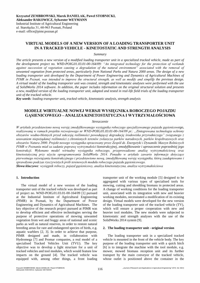
Fig. 1. The tracked vehicle during sedge cutting trials -
PIMR-BE archives
Rys. 1. Pojazd gąsienicowy podczas prób koszenia turzycy –
archiwum PIMR-BE
Fig. 2. The virtual model of the original version of the
loading transporter unit - PIMR-BE archives
Rys. 2. Model wirtualny pierwotnej wersji wysięgnika
roboczego – archiwum PIMR-BE
TVU field tests (Fig. 1, 3, 4) carried out during biomass
mowing and collection trials, demonstrated a necessity for
redesigning the original version of the loading transporter
unit in order to improve its torsional strength.
In the process of mowing field trials carried out in a
boggy and frequently uneven and heterogeneous land, it
was found out that the loading transporter unit with a
heavier grass mowing tool coupled with it, is exposed to
substantial dynamic forces and an excessive torsion of the
structure.
Field tests carried out under hard weather conditions
(various kind of dust, occasional showers), revealed
difficulties in controlling the movement of the tool module
locking pins in the quick hitch of the loading transporter
unit. Insufficient clearance on the locking pins in sand and
dust conditions, as well as the applied mechanism control
using flexible connectors, made it difficult to properly
control the locking mechanism.
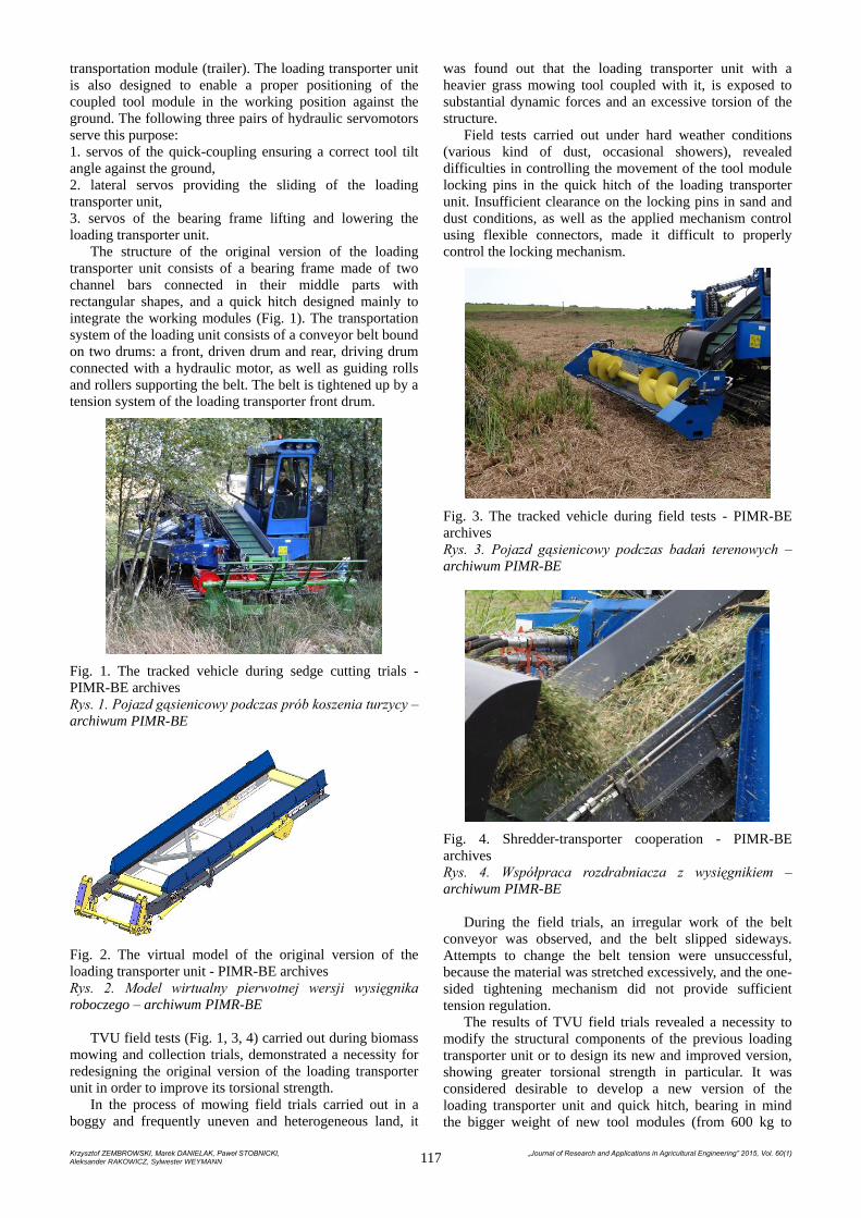
Fig. 3. The tracked vehicle during field tests - PIMR-BE
archives
Rys. 3. Pojazd gąsienicowy podczas badań terenowych –
archiwum PIMR-BE
Fig. 4. Shredder-transporter cooperation - PIMR-BE
archives
Rys. 4. Współpraca rozdrabniacza z wysięgnikiem –
archiwum PIMR-BE
During the field trials, an irregular work of the belt
conveyor was observed, and the belt slipped sideways.
Attempts to change the belt tension were unsuccessful,
because the material was stretched excessively, and the one-
sided tightening mechanism did not provide sufficient
tension regulation.
The results of TVU field trials revealed a necessity to
modify the structural components of the previous loading
transporter unit or to design its new and improved version,
showing greater torsional strength in particular. It was
considered desirable to develop a new version of the
loading transporter unit and quick hitch, bearing in mind
the bigger weight of new tool modules (from 600 kg to
Krzysztof ZEMBROWSKI, Marek DANIELAK, Paweł STOBNICKI, „Journal of Research and Applications in Agricultural Engineering” 2015, Vol. 60(1) Aleksander RAKOWICZ, Sylwester WEYMANN 118
approx. 720 kg) and a required increased range of tool
dislocation against the ground, as well as to ensure the right
depth of tool submersion under water.
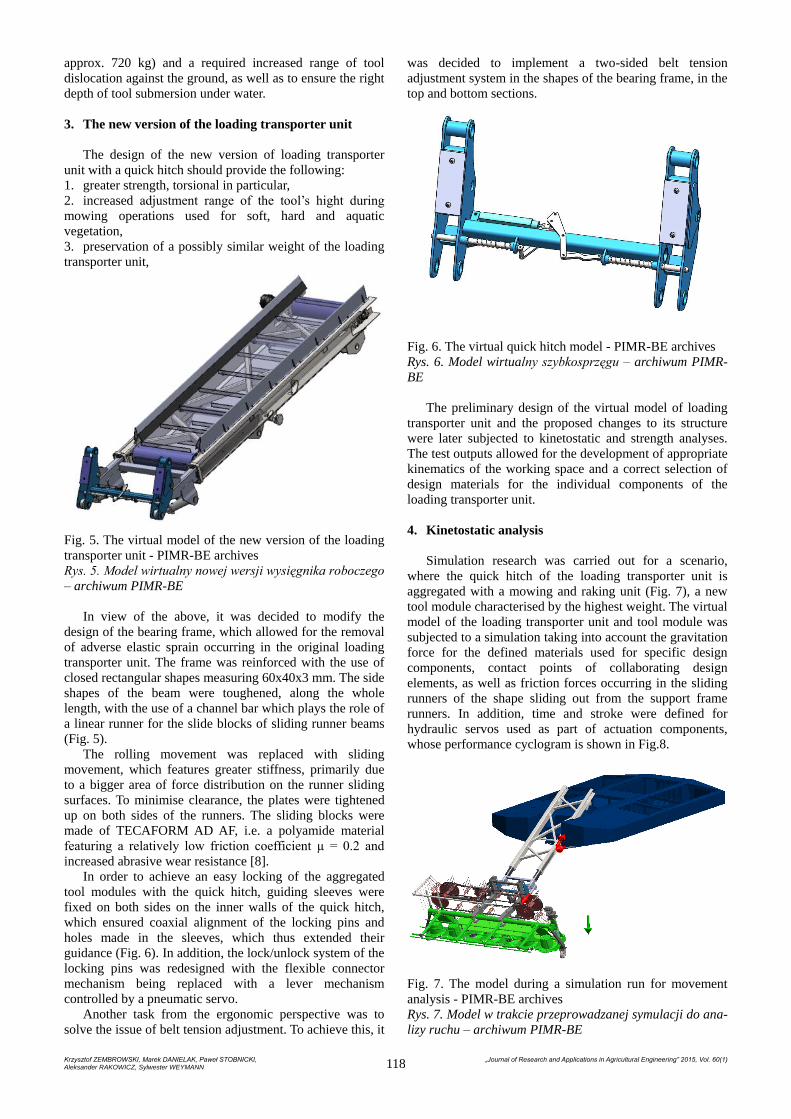
3. The new version of the loading transporter unit
The design of the new version of loading transporter
unit with a quick hitch should provide the following:
1. greater strength, torsional in particular,
2. increased adjustment range of the tool’s hight during
mowing operations used for soft, hard and aquatic
vegetation,
3. preservation of a possibly similar weight of the loading
transporter unit,
Fig. 5. The virtual model of the new version of the loading
transporter unit - PIMR-BE archives
Rys. 5. Model wirtualny nowej wersji wysięgnika roboczego
– archiwum PIMR-BE
In view of the above, it was decided to modify the
design of the bearing frame, which allowed for the removal
of adverse elastic sprain occurring in the original loading
transporter unit. The frame was reinforced with the use of
closed rectangular shapes measuring 60x40x3 mm. The side
shapes of the beam were toughened, along the whole
length, with the use of a channel bar which plays the role of
a linear runner for the slide blocks of sliding runner beams
(Fig. 5).
The rolling movement was replaced with sliding
movement, which features greater stiffness, primarily due
to a bigger area of force distribution on the runner sliding
surfaces. To minimise clearance, the plates were tightened
up on both sides of the runners. The sliding blocks were
made of TECAFORM AD AF, i.e. a polyamide material
featuring a relatively low friction coefficient µ = 0.2 and
increased abrasive wear resistance [8].
In order to achieve an easy locking of the aggregated
tool modules with the quick hitch, guiding sleeves were
fixed on both sides on the inner walls of the quick hitch,
which ensured coaxial alignment of the locking pins and
holes made in the sleeves, which thus extended their
guidance (Fig. 6). In addition, the lock/unlock system of the
locking pins was redesigned with the flexible connector
mechanism being replaced with a lever mechanism
controlled by a pneumatic servo.
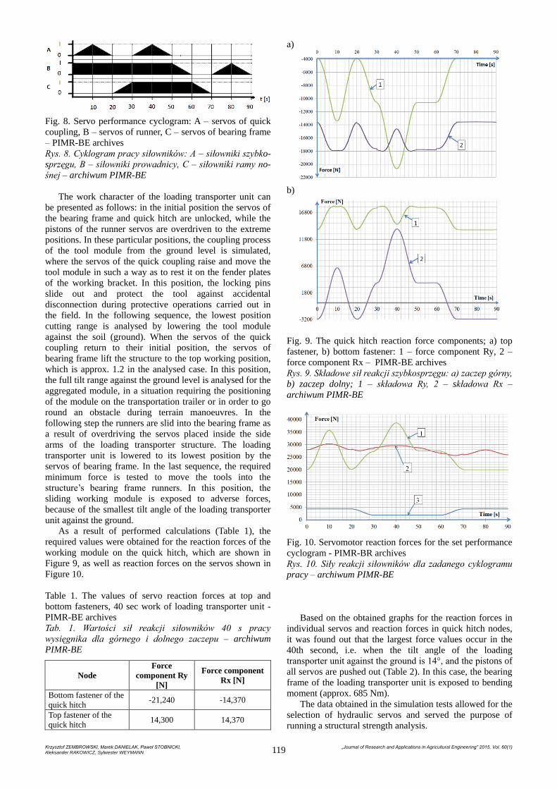
Another task from the ergonomic perspective was to
solve the issue of belt tension adjustment. To achieve this, it
was decided to implement a two-sided belt tension
adjustment system in the shapes of the bearing frame, in the
top and bottom sections.
Fig. 6. The virtual quick hitch model - PIMR-BE archives
Rys. 6. Model wirtualny szybkosprzęgu – archiwum PIMR-
BE
The preliminary design of the virtual model of loading
transporter unit and the proposed changes to its structure
were later subjected to kinetostatic and strength analyses.
The test outputs allowed for the development of appropriate
kinematics of the working space and a correct selection of
design materials for the individual components of the
loading transporter unit.
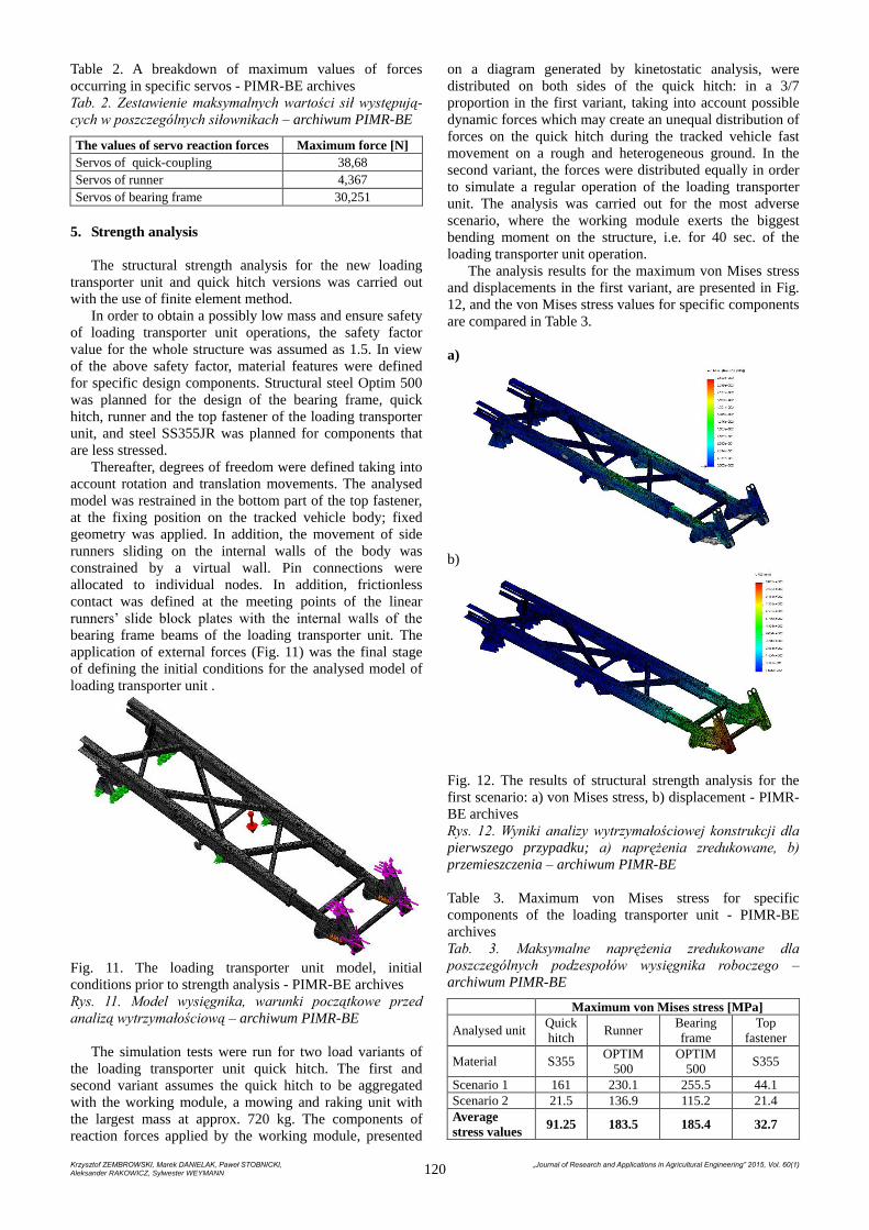
4. Kinetostatic analysis
Simulation research was carried out for a scenario,
where the quick hitch of the loading transporter unit is
aggregated with a mowing and raking unit (Fig. 7), a new
tool module characterised by the highest weight. The virtual
model of the loading transporter unit and tool module was
subjected to a simulation taking into account the gravitation
force for the defined materials used for specific design
components, contact points of collaborating design
elements, as well as friction forces occurring in the sliding
runners of the shape sliding out from the support frame
runners. In addition, time and stroke were defined for
hydraulic servos used as part of actuation components,
whose performance cyclogram is shown in Fig.8.
Fig. 7. The model during a simulation run for movement
analysis - PIMR-BE archives
Rys. 7. Model w trakcie przeprowadzanej symulacji do ana-
lizy ruchu – archiwum PIMR-BE
Krzysztof ZEMBROWSKI, Marek DANIELAK, Paweł STOBNICKI, „Journal of Research and Applications in Agricultural Engineering” 2015, Vol. 60(1) Aleksander RAKOWICZ, Sylwester WEYMANN 119
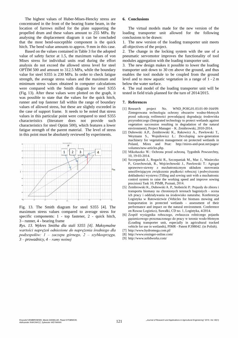
Fig. 8. Servo performance cyclogram: A – servos of quick
coupling, B – servos of runner, C – servos of bearing frame
– PIMR-BE archives
Rys. 8. Cyklogram pracy siłowników: A – siłowniki szybko-
sprzęgu, B – siłowniki prowadnicy, C – siłowniki ramy no-
śnej – archiwum PIMR-BE
The work character of the loading transporter unit can
be presented as follows: in the initial position the servos of
the bearing frame and quick hitch are unlocked, while the
pistons of the runner servos are overdriven to the extreme
positions. In these particular positions, the coupling process
of the tool module from the ground level is simulated,
where the servos of the quick coupling raise and move the
tool module in such a way as to rest it on the fender plates
of the working bracket. In this position, the locking pins
slide out and protect the tool against accidental
disconnection during protective operations carried out in
the field. In the following sequence, the lowest position
cutting range is analysed by lowering the tool module
against the soil (ground). When the servos of the quick
coupling return to their initial position, the servos of
bearing frame lift the structure to the top working position,
which is approx. 1.2 in the analysed case. In this position,
the full tilt range against the ground level is analysed for the
aggregated module, in a situation requiring the positioning
of the module on the transportation trailer or in order to go
round an obstacle during terrain manoeuvres. In the
following step the runners are slid into the bearing frame as
a result of overdriving the servos placed inside the side
arms of the loading transporter structure. The loading
transporter unit is lowered to its lowest position by the
servos of bearing frame. In the last sequence, the required
minimum force is tested to move the tools into the
structure’s bearing frame runners. In this position, the
sliding working module is exposed to adverse forces,
because of the smallest tilt angle of the loading transporter
unit against the ground.
As a result of performed calculations (Table 1), the
required values were obtained for the reaction forces of the
working module on the quick hitch, which are shown in
Figure 9, as well as reaction forces on the servos shown in
Figure 10.
Table 1. The values of servo reaction forces at top and
bottom fasteners, 40 sec work of loading transporter unit -
PIMR-BE archives
Tab. 1. Wartości sił reakcji siłowników 40 s pracy
wysięgnika dla górnego i dolnego zaczepu – archiwum
PIMR-BE
Node
Force
component Ry
[N]
Force component
Rx [N]
Bottom fastener of the
quick hitch -21,240 -14,370
Top fastener of the
quick hitch 14,300 14,370
a)
b)
Fig. 9. The quick hitch reaction force components; a) top
fastener, b) bottom fastener: 1 – force component Ry, 2 –
force component Rx – PIMR-BE archives
Rys. 9. Składowe sił reakcji szybkosprzęgu: a) zaczep górny,
b) zaczep dolny; 1 – składowa Ry, 2 – składowa Rx –
archiwum PIMR-BE
Fig. 10. Servomotor reaction forces for the set performance
cyclogram - PIMR-BR archives
Rys. 10. Siły reakcji siłowników dla zadanego cyklogramu
pracy – archiwum PIMR-BE
Based on the obtained graphs for the reaction forces in
individual servos and reaction forces in quick hitch nodes,
it was found out that the largest force values occur in the
40th second, i.e. when the tilt angle of the loading
transporter unit against the ground is 14°, and the pistons of
all servos are pushed out (Table 2). In this case, the bearing
frame of the loading transporter unit is exposed to bending
moment (approx. 685 Nm).
The data obtained in the simulation tests allowed for the
selection of hydraulic servos and served the purpose of
running a structural strength analysis.
Krzysztof ZEMBROWSKI, Marek DANIELAK, Paweł STOBNICKI, „Journal of Research and Applications in Agricultural Engineering” 2015, Vol. 60(1) Aleksander RAKOWICZ, Sylwester WEYMANN 120
Table 2. A breakdown of maximum values of forces
occurring in specific servos - PIMR-BE archives
Tab. 2. Zestawienie maksymalnych wartości sił występują-
cych w poszczególnych siłownikach – archiwum PIMR-BE
The values of servo reaction forces Maximum force [N]
Servos of quick-coupling 38,68
Servos of runner 4,367
Servos of bearing frame 30,251
5. Strength analysis
The structural strength analysis for the new loading
transporter unit and quick hitch versions was carried out
with the use of finite element method.
In order to obtain a possibly low mass and ensure safety
of loading transporter unit operations, the safety factor
value for the whole structure was assumed as 1.5. In view
of the above safety factor, material features were defined
for specific design components. Structural steel Optim 500
was planned for the design of the bearing frame, quick
hitch, runner and the top fastener of the loading transporter
unit, and steel SS355JR was planned for components that
are less stressed.
Thereafter, degrees of freedom were defined taking into
account rotation and translation movements. The analysed
model was restrained in the bottom part of the top fastener,
at the fixing position on the tracked vehicle body; fixed
geometry was applied. In addition, the movement of side
runners sliding on the internal walls of the body was
constrained by a virtual wall. Pin connections were
allocated to individual nodes. In addition, frictionless
contact was defined at the meeting points of the linear
runners’ slide block plates with the internal walls of the
bearing frame beams of the loading transporter unit. The
application of external forces (Fig. 11) was the final stage
of defining the initial conditions for the analysed model of
loading transporter unit .
Fig. 11. The loading transporter unit model, initial
conditions prior to strength analysis - PIMR-BE archives
Rys. 11. Model wysięgnika, warunki początkowe przed
analizą wytrzymałościową – archiwum PIMR-BE
The simulation tests were run for two load variants of
the loading transporter unit quick hitch. The first and
second variant assumes the quick hitch to be aggregated
with the working module, a mowing and raking unit with
the largest mass at approx. 720 kg. The components of
reaction forces applied by the working module, presented
on a diagram generated by kinetostatic analysis, were
distributed on both sides of the quick hitch: in a 3/7
proportion in the first variant, taking into account possible
dynamic forces which may create an unequal distribution of
forces on the quick hitch during the tracked vehicle fast
movement on a rough and heterogeneous ground. In the
second variant, the forces were distributed equally in order
to simulate a regular operation of the loading transporter
unit. The analysis was carried out for the most adverse
scenario, where the working module exerts the biggest
bending moment on the structure, i.e. for 40 sec. of the
loading transporter unit operation.
The analysis results for the maximum von Mises stress
and displacements in the first variant, are presented in Fig.
12, and the von Mises stress values for specific components
are compared in Table 3.
a)
b)
Fig. 12. The results of structural strength analysis for the
first scenario: a) von Mises stress, b) displacement - PIMR-
BE archives
Rys. 12. Wyniki analizy wytrzymałościowej konstrukcji dla
pierwszego przypadku; a) naprężenia zredukowane, b)
przemieszczenia – archiwum PIMR-BE
Table 3. Maximum von Mises stress for specific
components of the loading transporter unit - PIMR-BE
archives
Tab. 3. Maksymalne naprężenia zredukowane dla
poszczególnych podzespołów wysięgnika roboczego –
archiwum PIMR-BE
Maximum von Mises stress [MPa]
Analysed unit Quick
hitch Runner
Bearing
frame
Top
fastener
Material S355 OPTIM
500
OPTIM
500 S355
Scenario 1 161 230.1 255.5 44.1
Scenario 2 21.5 136.9 115.2 21.4
Average
stress values 91.25 183.5 185.4 32.7
Krzysztof ZEMBROWSKI, Marek DANIELAK, Paweł STOBNICKI, „Journal of Research and Applications in Agricultural Engineering” 2015, Vol. 60(1) Aleksander RAKOWICZ, Sylwester WEYMANN 121
The highest values of Huber-Mises-Hencky stress are
concentrated in the front of the bearing frame beam, in the
location of furrows milled for the plate supporting the
propelled drum and these values amount to 255 MPa. By
analysing the displacement diagram it can be concluded
that the most bend-susceptible component is the quick
hitch. The bend value amounts to approx. 9 mm in this case.
Based on the values contained in Table 3 for the adopted
value of safety factor at 1.5, the maximum values of von
Mises stress for individual units read during the effort
analysis do not exceed the allowed stress level for steel
OPTIM 500 and amount to 312.5 MPa, while the boundary
value for steel S355 is 230 MPa. In order to check fatigue
strength, the average stress values and the maximum and
minimum stress values obtained in computer calculations
were compared with the Smith diagram for steel S355
(Fig. 13). After these values were plotted on the graph, it
was possible to state that the values for the quick hitch,
runner and top fastener fall within the range of boundary
values of allowed stress, but these are slightly exceeded in
the case of support frame. It needs to be noted that stress
values in this particular point were compared to steel S355
characteristics (literature does not provide such
characteristics for steel Optim 500), which features a lower
fatigue strength of the parent material. The level of stress
in this point must be absolutely reviewed by experiments.
Fig. 13. The Smith diagram for steel S355 [4]. The
maximum stress values compared to average stress for
specific components: 1 - top fastener, 2 - quick hitch,
3 - runner, 4 - bearing frame
Rys. 13. Wykres Smitha dla stali S355 [4]. Maksymalne
wartości naprężeń odniesione do naprężenia średniego dla
podzespołów: 1 – zaczepu górnego, 2 – szybkosprzęgu,
3 – prowadnicy, 4 – ramy nośnej
6. Conclusions
The virtual models made for the new version of the
loading transporter unit allowed for the following
conclusions to be drawn:
1. The new version of the loading transporter unit meets
all objectives of the project.
2. The change in the locking system with the use of a
pneumatic servomotor improves the functionality of tool
modules aggregation with the loading transporter unit.
3. The new design makes it possible to lower the loading
transporter unit down to 30 cm above the ground, and thus
enables the tool module to be coupled from the ground
level and to mow aquatic vegetation in a range of 1 - 2 m
below the water surface.
4. The real model of the loading transporter unit will be
tested in field trials planned for the turn of 2014/2015.
7. References
[1] Research project No. WND_POIG.01.03.01-00-164/09:
Zintegrowana technologia ochrony obszarów wodno-błotnych
przed sukcesją roślinności powodującej degradację środowiska
przyrodniczego (Integrated technology to protect wetlands against
vegetation succession resulting in degradation of the natural
environment), Project Manager – K. Zembrowski, 2010-2014.
[2] Dubowski A.P., Zembrowski K., Rakowicz A., Pawłowski T.,
Weymann S., Wojniłowicz Ł.: Developing new-generation
machinery for vegetation management on protected wetlands in
Poland, Mires and Peat: http://mires-and-peat.net/pages/
volumes/new-articles.php.
[3] Mikołuszko W.: Ochrona przed ochroną. Tygodnik Powszechny,
10, 19-03-2014.
[4] Szczepaniak J., Rogacki R., Szczepaniak M., Mac J., Wasieczko
P., Grzechowiak, R., Wojciechowski J., Pawłowski T.: Agregat
uprawowo-siewny z mechatronicznym układem sterowania
umożliwiającym zwiększenie prędkości roboczej i podwyższenie
dokładności wysiewu (Tilling and sowing unit with a mechatronic
control system to raise the working speed and improve sowing
precision) Task 10, PIMR, Poznań, 2014.
[5] Zembrowski K., Dubowski A. P., Stobnicki P.: Pojazdy do zbioru i
transportu biomasy na chronionych terenach bagnistych - ocena
ich pracy i oddziaływania na środowisko naturalne. Konferencja
Logistyka w Ratownictwie (Vehicles for biomass mowing and
transportation in protected wetlands - assessment of their
performance and impact on the natural environment. Conference
on Rescue Logistics), Suwałki, CD no. 1, Logistyka, 4/2014.
[6] Zespół wysięgnika roboczego, zwłaszcza rolniczego pojazdu
gąsienicowego przeznaczonego do pracy w terenie wodo-błotnym
(Loading transporter unit, especially in agricultural tracked
vehicle for use in wetlands), PIMR - Patent P.398042. (in Polish).
[7] http://www.hydromega.com.pl/
[8] http://www.ensinger-online.com/
[9] http://www.solidworks.com/