STUDIES ON STRESS AND STRAIN STATE IN COLD ORBITAL FORGING · PDF filea r c h i v e s o f m e...
7
A R C H I V E S O F M E T A L L U R G Y A N D M A T E R I A L S Volume 58 2013 Issue 4 DOI: 10.2478/amm-2013-0149 G. SAMOLYK * STUDIES ON STRESS AND STRAIN STATE IN COLD ORBITAL FORGING A AlMgSi ALLOY FLANGE PIN BADANIA STANU NAPRĘŻENIA I ODKSZTALCENIA W PRASOWANIU OBWIEDNIOWYM SWORZNIA Z KOLNIERZEM ZE STOPU AlMgSi The orbital forging is one of the metal forming processes which enables the manufacture of products through worm or cold working. A characteristic feature of this technological process is the use of a special wobbling motion of one of the tools in order to reduce the required forming force. This is particularly advantageous during the formation of products in the shape of a disc or a flange pin. Unfortunately, typical constraints of cold orbital forging are: uncontrolled buckling, loss of shape stability (“mushroom effect”) and cracks. They depend on the technological parameters of the process and their cause can be explained on the basis of e.g. workpiece stress state analysis, which is a difficult task due to the complexity of orbital forging process. The article discusses the issues of stress and strain in cold orbital forged parts of the flange pin type, made of AlMgSi aluminum alloy. The results of the presented FEM simulation, verified experimentally, explain the influence of the theoretical aspects of this process on its implementation conditions. It is assumed that orbital forging is performed on the PXW-100A press and the numerical model takes into account all possible variants of the process. Debate boils down to discussing the stress and strain state (e.g. analyzing the stress and strain rate fields) occurring in the workpiece in the context of chosen technological parameters and constrains of orbital forging process. Keywords: orbital forging, stress and strain state, aluminium alloy, FEM, experiment Prasowanie obwiedniowe jest jedną z technologii obróbki plastycznej, która umożliwia wytwarzanie wyrobów poprzez ich ksztaltowanie na zimno lub cieplo. Wyroby prasowane obwiedniowo charakteryzują się stosunkowo dużą jakością powierzchni oraz malą tolerancją wymiarową. Charakterystyczną cechą tego procesu technologicznego jest zastosowanie specjalnego ru- chu wahającego jednego z narzędzi w celu obniżenia wymaganej sily ksztaltowania. Szczególnie korzystne jest to podczas ksztaltowania wyrobów typu tarcza lub sworzeń z kolnierzem. Typowymi ograniczeniami prasowania obwiedniowego są nie- kontrolowane wyboczenie, utrata stateczności ksztaltu oraz pęknięcia. Zależą one od parametrów technologicznych procesu, a ich przyczynę można wyjaśnić na podstawie np. analizy stanu naprężenia panującego w wyprasce. Z uwagi na zlożony cha- rakter prasowania obwiedniowego jest to zadanie trudne. W artykule omówiono zagadnienia stanu naprężenia i odksztalcenia w prasowaniu obwiedniowym części typu sworzeń z kolnierzem, która jest wykonana ze stopu aluminium AlMgSi. Przedstawione wyniki symulacji, zweryfikowanej doświadczalnie, wyjaśniają znaczenie aspektów teoretycznych tego procesu na jego warunki realizacji. Zaklada się, że prasowanie obwiedniowe jest realizowane na prasie PXW-100A, a model numeryczny uwzględnia wszystkie możliwe warianty realizacji procesu na tej maszynie. Dyskusja sprowadza się do omówienie stanu naprężenia i od- ksztalcenia (analizując prędkość odksztalcenia) panującego w wyprasce w kontekście wybranych parametrów technologicznych i ograniczeń procesu prasowania obwiedniowego. 1. Introduction The orbital forging is a method of cold or worm working of parts, which is based on methods patented in 1920 by Slick and in 1922 by Massey [1]. The first machine, allowing for the production of parts using this method, was manufactured in sixties of the 20th century. In the same time, Marciniak and next Barnet developed an innovative mechanism driving the upper die what allowed for the realization of the orbital forging process with using different schemes of the wobble-die move- ment. This solution is currently used in most special machines, e.g., such as PXW series presses (produced by the no longer existing company PLASOMAT – according to Marciniak’s de- sign), T series presses – from the Swiss company H.SCHMiD (according to Barnet’s design) and MCOF series presses – from the Japanese company MORI IRON WORKS CO. The typical patterns of upper die wobbling motion schemes have been shown in Figure 1 [1-5]. In practice, two basic variants of workpiece forging are encountered. In one of these variants a tool makes a wobbling motion. This basic form of orbital forging, handled by, e.g., PXW presses, is characterized by the fact that the upper die makes a spherical motion around a fixed point lying in contact with the shaped material (Figure 1). The lower die together * LUBLIN UNIVERSITY OF TECHNOLOGY, 38 NADBYSTRZYCKA STR., 20-618 LUBLIN, POLAND
Transcript of STUDIES ON STRESS AND STRAIN STATE IN COLD ORBITAL FORGING · PDF filea r c h i v e s o f m e...
A R C H I V E S O F M E T A L L U R G Y A N D M A T E R I A L S
Volume 58 2013 Issue 4
DOI: 10.2478/amm-2013-0149
G. SAMOŁYK∗
STUDIES ON STRESS AND STRAIN STATE IN COLD ORBITAL FORGING A AlMgSi ALLOY FLANGE PIN
BADANIA STANU NAPRĘŻENIA I ODKSZTAŁCENIA W PRASOWANIU OBWIEDNIOWYM SWORZNIA Z KOŁNIERZEM ZESTOPU AlMgSi
The orbital forging is one of the metal forming processes which enables the manufacture of products through worm orcold working. A characteristic feature of this technological process is the use of a special wobbling motion of one of the toolsin order to reduce the required forming force. This is particularly advantageous during the formation of products in the shapeof a disc or a flange pin. Unfortunately, typical constraints of cold orbital forging are: uncontrolled buckling, loss of shapestability (“mushroom effect”) and cracks. They depend on the technological parameters of the process and their cause can beexplained on the basis of e.g. workpiece stress state analysis, which is a difficult task due to the complexity of orbital forgingprocess. The article discusses the issues of stress and strain in cold orbital forged parts of the flange pin type, made of AlMgSialuminum alloy. The results of the presented FEM simulation, verified experimentally, explain the influence of the theoreticalaspects of this process on its implementation conditions. It is assumed that orbital forging is performed on the PXW-100Apress and the numerical model takes into account all possible variants of the process. Debate boils down to discussing thestress and strain state (e.g. analyzing the stress and strain rate fields) occurring in the workpiece in the context of chosentechnological parameters and constrains of orbital forging process.
Keywords: orbital forging, stress and strain state, aluminium alloy, FEM, experiment
Prasowanie obwiedniowe jest jedną z technologii obróbki plastycznej, która umożliwia wytwarzanie wyrobów poprzez ichkształtowanie na zimno lub ciepło. Wyroby prasowane obwiedniowo charakteryzują się stosunkowo dużą jakością powierzchnioraz małą tolerancją wymiarową. Charakterystyczną cechą tego procesu technologicznego jest zastosowanie specjalnego ru-chu wahającego jednego z narzędzi w celu obniżenia wymaganej siły kształtowania. Szczególnie korzystne jest to podczaskształtowania wyrobów typu tarcza lub sworzeń z kołnierzem. Typowymi ograniczeniami prasowania obwiedniowego są nie-kontrolowane wyboczenie, utrata stateczności kształtu oraz pęknięcia. Zależą one od parametrów technologicznych procesu,a ich przyczynę można wyjaśnić na podstawie np. analizy stanu naprężenia panującego w wyprasce. Z uwagi na złożony cha-rakter prasowania obwiedniowego jest to zadanie trudne. W artykule omówiono zagadnienia stanu naprężenia i odkształcenia wprasowaniu obwiedniowym części typu sworzeń z kołnierzem, która jest wykonana ze stopu aluminium AlMgSi. Przedstawionewyniki symulacji, zweryfikowanej doświadczalnie, wyjaśniają znaczenie aspektów teoretycznych tego procesu na jego warunkirealizacji. Zakłada się, że prasowanie obwiedniowe jest realizowane na prasie PXW-100A, a model numeryczny uwzględniawszystkie możliwe warianty realizacji procesu na tej maszynie. Dyskusja sprowadza się do omówienie stanu naprężenia i od-kształcenia (analizując prędkość odkształcenia) panującego w wyprasce w kontekście wybranych parametrów technologicznychi ograniczeń procesu prasowania obwiedniowego.
1. Introduction
The orbital forging is a method of cold or worm workingof parts, which is based on methods patented in 1920 by Slickand in 1922 by Massey [1]. The first machine, allowing forthe production of parts using this method, was manufacturedin sixties of the 20th century. In the same time, Marciniak andnext Barnet developed an innovative mechanism driving theupper die what allowed for the realization of the orbital forgingprocess with using different schemes of the wobble-die move-ment. This solution is currently used in most special machines,e.g., such as PXW series presses (produced by the no longer
existing company PLASOMAT – according to Marciniak’s de-sign), T series presses – from the Swiss company H.SCHMiD(according to Barnet’s design) and MCOF series presses –from the Japanese company MORI IRON WORKS CO. Thetypical patterns of upper die wobbling motion schemes havebeen shown in Figure 1 [1-5].
In practice, two basic variants of workpiece forging areencountered. In one of these variants a tool makes a wobblingmotion. This basic form of orbital forging, handled by, e.g.,PXW presses, is characterized by the fact that the upper diemakes a spherical motion around a fixed point lying in contactwith the shaped material (Figure 1). The lower die together
∗ LUBLIN UNIVERSITY OF TECHNOLOGY, 38 NADBYSTRZYCKA STR., 20-618 LUBLIN, POLAND

1184
with the ejector moves in a straight line along the main axis ofthe press. In some works, the orbital forging process, in whichthe upper die makes an agreeable motion with the circularmovement scheme, is also called a rotary forging. The secondvariant of workpiece shaping is rotation forming (sometimescalled an orbital rolling), in which all the tools and the shapedmaterial make a rotary motion relative to the main axis of thepress and the upper die oscillation effect is obtained throughits defined inclination relative to the main axis of the press[1-4].
Fig. 1. The technical solution of the orbital forging machine devel-oped by Marciniak (a) and the four typical schemes of wobblingmotion of an upper die used on PXW-series presses
Many scientific papers discuss the forging process, eitherrotary or orbital, in which the upper die makes a simple cir-cular movement (Figure 1). The investigations, which relateto orbital or rotary forging and based on numerical analy-sis, are curried out continuously for over 30 years, e.g. [2-4,6-9, 12-18]. Detailed study of these papers indicates that thistopic is relatively difficult and the theoretical and technolog-ical knowledge about the orbital forging is still incomplete.Particularly noteworthy are several works, which significantlyenriched the knowledge about the orbital (or rotary) forgingprocess. For example, Ziółkiewicz and Garczyński [5] done ageneral overview of the state of knowledge. Oh and Choi [6, 7]adopted the upper-bound method to analyse the stress state andcalculate a forming force. Next, Canta et al. [8] described themajor aspects of energy distribution in a rotary forging. Liu etal. [12] discussed e.g. the mushroom effect and Decheng et al.[13] explained the other important limitations of the process.Guangchun et al. [15] analysed cold rotary forging the ringparts using the rigid-plastic FE model. While, Han and Hou[16-18] adopted the elastic-plastic FE model to analyse a ro-tary forging the ring and cylindrical parts. Whereas, Rusz andDyja [19] presented the influence of the chosen technologicalparameters on the orbital forging process. For several yearsat the Lublin University of Technology intensive research hasbeen conducted aimed at extending the current state of theo-retical knowledge about the processes and technology of or-bital forging, e.g., [3, 4]. The scope of these works has beenincluded both experimental studies using PXW-100A produc-tion press, as well as finite element method (FEM) numericalanalysis [4, 10, 11]. This article presents the selected resultsof the research, which discuss the issues of stress and strain
in the flange pin type workpiece, orbital forged with the useof different upper die wobbling motion schemes. In there hasbeen presented the relationship of these theoretical aspects tothe major technological parameters of the cold orbital forging,too. Finally it should be noted, that the presented results ofFEM calculation, which relate to different schemes of wob-bling motion of the die, was obtained by the author for thefirst time.
2. Scope of studies
2.1. A numerical model of orbital forging process
Numerical analysis was performed using the finite el-ement method (FEM) based on a commercial softwareDEFORM-3D. The geometric scheme of a model of the or-bital forging process is shown in Figure 2. Tools (upper die,lower die and ejector) are modelled as rigid bodies, while theworkpiece is a rigid-plastic body divided into 80 thousandtetragonal four-nodal elements. The calculation assumes thatthe workpiece is made of AlMgSi aluminium alloy (chemicalcomposition provided by Tabal Co., Poland), for which thestrengthening curve was assumed in the form of equation (1)determined in own research published at the previous work,e.g. [3, 21].
σp = 684 · φ0.098 · φ̇0.134 · exp (−0.0058 · T ) (1)
where σp is yield stress, φ is plastic strain; φ̇ is strain rate andT is temperature of workpiece.
Fig. 2. Numerical model of orbital forging process of a flange pin(a) and the dimensions of workpiece and the forging, where: h0, d0
are initial dimensions; h1, d1, g are final dimensions; γ is upper dieinclination angle (2◦)
Friction acting on the contact surface of the material withthe tools was determined on the basis of constant frictionmodel, for which the friction factor m = 0.45 was adopted.Although the workpiece is cold worked (initial temperature isequal to 20◦C), the calculation uses the full thermo-mechanicalmodel for which the heat transfer coefficient between the ob-jects is equal to 24·103 W·m−2·K−1.
The study assumes that the diameter of the initial work-piece d0 = 20 mm and its initial height h0 is 34 mm. Simula-tion of the forging process was performed assuming a constantvelocity of the lower tools (lower die and ejector) of maximumvalue vm = 4.1 mm·s−1. After the workpiece reached the de-sired flange thickness g = 3.65 mm, the lower die and ejectorwere stopped in order to obtain the effect of calibration of
1185
the flange frontal area by the wobbling die. Then, after 0.6seconds, the upper and lower dies were moved away from theworkpiece with the velocity of 40 mm·s−1. This resulted in theeffect of removing the part from the lower die with the use ofthe ejector.
2.2. Modelling the wobbling motion of the upper die
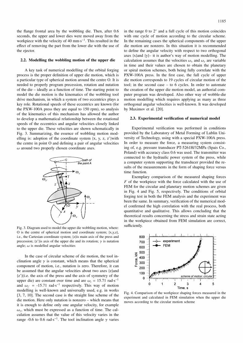
A key task of numerical modelling of the orbital forgingprocess is the proper definition of upper die motion, which isa particular type of spherical motion around the centre O. It isneeded to properly program precession, rotation and nutationof the die – ideally as a function of time. The starting point tomodel the die motion is the kinematics of the wobbling tooldrive mechanism, in which a system of two eccentrics plays akey role. Rotational speeds of these eccentrics are known (forthe PXW-100A press they are equal to 150 rpm), so analysisof the kinematics of this mechanism has allowed the authorto develop a mathematical relationship between the rotationalspeeds of the eccentrics and angular velocities closely linkedto the upper die. These velocities are shown schematically inFig. 3. Summarizing, the essence of wobbling motion mod-elling is: adoption of the coordinate system {x, y, z, z’}withthe centre in point O and defining a pair of angular velocitiesω around two properly chosen coordinate axes.
Fig. 3. Diagram used to model the upper die wobbling motion, where:O is the centre of spherical motion and coordinate system; {x,y,z},i.e., the Cartesian coordinate system; {z}is main axis of the press andprecession; {z’}is axis of the upper die and its rotation; γ is nutationangle; ω is modelled angular velocities
In the case of circular scheme of die motion, the tool in-clination angle γ is constant, which means that the sphericalcomponent of motion, i.e., nutation is zero. Therefore, it canbe assumed that the angular velocities about two axes {z}and{z’}(i.e. the axis of the press and the axis of symmetry of theupper die) are constant over time and are ωz = 15.71 rad·s−1and ωz′ = -15.71 rad·s−1 respectively. This way of motionmodelling is well-known and universally used, e.g. in works[3, 7, 10]. The second case is the straight line scheme of thedie motion. Here only nutation is nonzero – which means thatit is enough to define only one angular velocity, for exampleωy, which must be expressed as a function of time. The cal-culation assumes that the value of this velocity varies in therange -0.6 to 0.6 rad·s−1. The tool inclination angle γ varies
in the range 0 to 2◦ and a full cycle of this motion coincideswith one cycle of motion according to the circular scheme.In the remaining cases the spherical components of the upperdie motion are nonzero. In this situation it is recommendedto define the angular velocity with respect to two orthogonalaxes {x}and {y}– it is author’s way of motion modelling. Thecalculation assumes that the velocities ωx and ωy are variablein time and their values are chosen to obtain the planetaryor spiral motion schemes, both being fully correlate with thePXW-100A press. In the first case, the full cycle of upperdie motion corresponds to 19 cycles of circular motion of thetool; in the second case – to 6 cycles. In order to automatethe creation of the upper die motion model, an authorial com-puter program was developed. Also other way of wobble-diemotion modelling which requires applying as many as threeorthogonal angular velocities is well-known. It was developedby Maximov et al. [20].
2.3. Experimental verification of numerical model
Experimental verification was performed in conditionsprovided by the Laboratory of Metal Forming of Lublin Uni-versity of Technology, using with a special PXW-100A press.In order to measure the force, a measuring system consist-ing of, e.g. pressure transducer PT-5261H/32MPa (Spais Co.,Poland) with accuracy class 0.6 was used. The transmitter wasconnected to the hydraulic power system of the press, whilea computer system supporting the transducer provided the re-sults of the measurements in the form of shaping force versustime function.
Exemplary comparison of the measured shaping forcesF of the workpiece with the force calculated with the use ofFEM for the circular and planetary motion schemes are givenin Fig. 4 and Fig. 5, respectively. The conditions of orbitalforging test in both the FEM analysis and the experiment wasbeen the same. In summary, verification of the numerical mod-el confirmed the high correlation with the real process, bothquantitative and qualitative. This allows concluding that thetheoretical results concerning the stress and strain state actingin the workpiece obtained from FEM simulation are correct,sufficiently.
Fig. 4. Comparison of the workpiece shaping forces measured in theexperiment and calculated in FEM simulation when the upper diemoves according to the circular motion scheme
1186
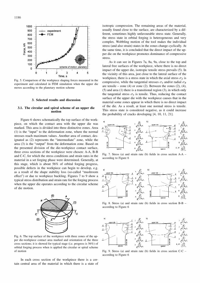
Fig. 5. Comparison of the workpiece shaping forces measured in theexperiment and calculated in FEM simulation when the upper diemoves according to the planetary motion scheme
3. Selected results and discussion
3.1. The circular and spiral scheme of an upper diemotion
Figure 6 shows schematically the top surface of the work-piece, on which the contact area with the upper die wasmarked. This area is divided into three distinctive zones. Area(1) is the “input” to the deformation zone, where the normalstresses reach maximum values. Another area of contact, des-ignated as (2) represents the “intermediate” zone, while thearea (3) is the “output” from the deformation zone. Based onthe presented division of the die-workpiece contact surface,three cross sections of the workpiece were chosen: A-A, B-Band C-C, for which the stress conditions and strain rates in thematerial in a set forging phase were determined. Generally, atthis stage, which is about 56% of orbital forging progress,possible defects in the workpiece can begin to develop, e.g.as a result of the shape stability loss (so-called “mushroomeffect”) or due to workpiece buckling. Figures 7 to 9 show atypical stress distribution and strain rate for the forging processwhen the upper die operates according to the circular schemeof die motion.
Fig. 6. The top surface of the workpiece with three zones of the up-per die-workpiece contact area marked and orientation of the threecross sections; it is showed for typical stage (i.e. progress is 56%) oforbital forging process when is applied the circular or spiral schemeof motion
In each cross section of the workpiece there is a cer-tain central area of the material in which there is a state of
isotropic compression. The remaining areas of the material,usually found close to the surface, are characterized by a dif-ferent, sometimes highly unfavourable stress state. Generally,the stress state in orbital forging is heterogeneous and verycomplex. Wobbling motion of the tool makes the individualstress (and also strain) states in the zones change cyclically. Atthe same time, it is concluded that the direct impact of the up-per die on the workpiece promotes dominance of compressivestress.
As it can see in Figures 7a, 8a, 9a, close to the top andlateral free surfaces of the workpiece, where there is no directimpact of the upper die, isotropic tensile stress prevails (5). Inthe vicinity of this area, just close to the lateral surface of theworkpiece, there is a stress state in which the axial stress σZ iscompressive, while the tangential stresses σθ and/or radial σR
are tensile – zone (4) or zone (2). Between the zones (2), (4),(5) and area (1) there is a transitional region (3), in which onlythe tangential stress σθ is tensile. Thus, reducing the contactsurface of the upper die with the workpiece causes that in thematerial some zones appear in which there is no direct impactof the die. As a result, at least one normal stress is tensile.This stress state is considered negative, as it could increasethe probability of cracks developing [4, 10, 11, 21].
Fig. 7. Stress (a) and strain rate (b) fields in cross section A-A –according to Figure 6
Fig. 8. Stress (a) and strain rate (b) fields in cross section B-B –according to Figure 6
Fig. 9. Stress (a) and strain rate (b) fields in cross section C-C –according to Figure 6
1187
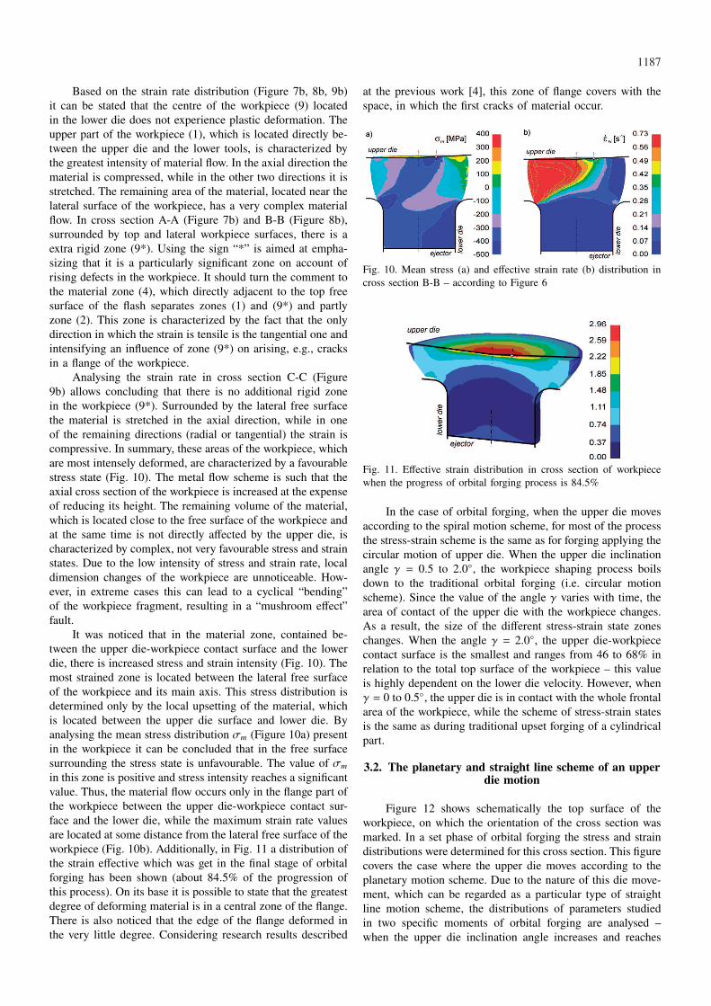
Based on the strain rate distribution (Figure 7b, 8b, 9b)it can be stated that the centre of the workpiece (9) locatedin the lower die does not experience plastic deformation. Theupper part of the workpiece (1), which is located directly be-tween the upper die and the lower tools, is characterized bythe greatest intensity of material flow. In the axial direction thematerial is compressed, while in the other two directions it isstretched. The remaining area of the material, located near thelateral surface of the workpiece, has a very complex materialflow. In cross section A-A (Figure 7b) and B-B (Figure 8b),surrounded by top and lateral workpiece surfaces, there is aextra rigid zone (9*). Using the sign “*” is aimed at empha-sizing that it is a particularly significant zone on account ofrising defects in the workpiece. It should turn the comment tothe material zone (4), which directly adjacent to the top freesurface of the flash separates zones (1) and (9*) and partlyzone (2). This zone is characterized by the fact that the onlydirection in which the strain is tensile is the tangential one andintensifying an influence of zone (9*) on arising, e.g., cracksin a flange of the workpiece.
Analysing the strain rate in cross section C-C (Figure9b) allows concluding that there is no additional rigid zonein the workpiece (9*). Surrounded by the lateral free surfacethe material is stretched in the axial direction, while in oneof the remaining directions (radial or tangential) the strain iscompressive. In summary, these areas of the workpiece, whichare most intensely deformed, are characterized by a favourablestress state (Fig. 10). The metal flow scheme is such that theaxial cross section of the workpiece is increased at the expenseof reducing its height. The remaining volume of the material,which is located close to the free surface of the workpiece andat the same time is not directly affected by the upper die, ischaracterized by complex, not very favourable stress and strainstates. Due to the low intensity of stress and strain rate, localdimension changes of the workpiece are unnoticeable. How-ever, in extreme cases this can lead to a cyclical “bending”of the workpiece fragment, resulting in a “mushroom effect”fault.
It was noticed that in the material zone, contained be-tween the upper die-workpiece contact surface and the lowerdie, there is increased stress and strain intensity (Fig. 10). Themost strained zone is located between the lateral free surfaceof the workpiece and its main axis. This stress distribution isdetermined only by the local upsetting of the material, whichis located between the upper die surface and lower die. Byanalysing the mean stress distribution σm (Figure 10a) presentin the workpiece it can be concluded that in the free surfacesurrounding the stress state is unfavourable. The value of σm
in this zone is positive and stress intensity reaches a significantvalue. Thus, the material flow occurs only in the flange part ofthe workpiece between the upper die-workpiece contact sur-face and the lower die, while the maximum strain rate valuesare located at some distance from the lateral free surface of theworkpiece (Fig. 10b). Additionally, in Fig. 11 a distribution ofthe strain effective which was get in the final stage of orbitalforging has been shown (about 84.5% of the progression ofthis process). On its base it is possible to state that the greatestdegree of deforming material is in a central zone of the flange.There is also noticed that the edge of the flange deformed inthe very little degree. Considering research results described
at the previous work [4], this zone of flange covers with thespace, in which the first cracks of material occur.
Fig. 10. Mean stress (a) and effective strain rate (b) distribution incross section B-B – according to Figure 6
Fig. 11. Effective strain distribution in cross section of workpiecewhen the progress of orbital forging process is 84.5%
In the case of orbital forging, when the upper die movesaccording to the spiral motion scheme, for most of the processthe stress-strain scheme is the same as for forging applying thecircular motion of upper die. When the upper die inclinationangle γ = 0.5 to 2.0◦, the workpiece shaping process boilsdown to the traditional orbital forging (i.e. circular motionscheme). Since the value of the angle γ varies with time, thearea of contact of the upper die with the workpiece changes.As a result, the size of the different stress-strain state zoneschanges. When the angle γ = 2.0◦, the upper die-workpiececontact surface is the smallest and ranges from 46 to 68% inrelation to the total top surface of the workpiece – this valueis highly dependent on the lower die velocity. However, whenγ = 0 to 0.5◦, the upper die is in contact with the whole frontalarea of the workpiece, while the scheme of stress-strain statesis the same as during traditional upset forging of a cylindricalpart.
3.2. The planetary and straight line scheme of an upperdie motion
Figure 12 shows schematically the top surface of theworkpiece, on which the orientation of the cross section wasmarked. In a set phase of orbital forging the stress and straindistributions were determined for this cross section. This figurecovers the case where the upper die moves according to theplanetary motion scheme. Due to the nature of this die move-ment, which can be regarded as a particular type of straightline motion scheme, the distributions of parameters studiedin two specific moments of orbital forging are analysed –when the upper die inclination angle increases and reaches

1188
its maximum (Fig. 12a) and when this angle decreases andits instantaneous value is γ = 1.6◦. These are two extremecases for which the upper die-workpiece contact surface isrespectively the largest (ca. 90%) and lowest (ca. 64%) thanthe whole volume of the material.
Fig. 12. The top surface of the workpiece with the upperdie-workpiece contact area marked and the cross section orientation;it is showed for typical stages of orbital forging process when is ap-plied the planetary or straight line scheme of motion: a) progress is56.4% and current angle γ = 2.0◦, b) progress is 61.3% and currentangle γ = 1.6◦; (+) means the angle γ is in increasing phase, (-)means the angle γ is in decreasing phase
The following Figs 13 and 14 show a typical stress andstrain rate distribution for the orbital forging process in theconditions on the PXW press, when the planetary motionscheme has been applied. When the upper die-workpiece con-tact area is the largest, the vast majority of the workpiece crosssection D-D (Fig. 13a) area is characterized by a favourable,isotropic compressive stress state (1). At the free surface ofthe workpiece there are zones of the material in which at leastone normal stress is tensile. In the right part of the crosssection, i.e. the side where the upper die directly affects thematerial, there is a zone (3) in which only the tangential stressσθ is tensile. But on the opposite side of the workpiece axis,where the upper die is not in contact with the top surfaceof the material, the zone (3) is surrounded by three differentmaterial zones, which are adjacent to the free surface of theworkpiece. On the border between the top and lateral surface(5) there is the most unfavourable, isotropic tensile stress state.The calculation results showed that with increasing lower dievelocity vm the zone narrows – this is caused mainly by theincrease of upper die-workpiece contact area.
Fig. 13. Stress (a) and strain rate (b) fields in cross section D-D –according to Figure 12a
Analysis of the strain rate (Figure 13b) determined incross section D-D allows distinguishing four main zones ofthe material. The workpiece centre (9) does not experienceplastic deformation. However, the central part of the forged
flange (1) is characterized by such a strain state in whichcompressive strain occurs in the axial direction, while in theremaining two directions the strain is tensile. Thus, such a stateof deformation causes an increase of the axial cross sectionat the expense of reducing the flange height. However, thechange of flange dimensions is uneven, because close to thefree surfaces of the workpiece some specific material zonesexist in which the strain negatively affects the forging processstability. On the right side of the workpiece axis, where theupper die affects the material directly, there is a zone (4) wherethe radial strain is compressive – it causes local inhibition ofuniform diameter increase during the process. On the otherside of the workpiece axis the material zone is much larger.In addition, there are zones in which the strain is unfavourableat least in one direction. In zone (6) the material is additionallystretched in axial direction and in zone (5) there occurs excessmaterial flow in a radial direction. This happens because inthe remaining two directions the strain is compressive. If thelower die velocity vm is too small, the relative intensity ofmaterial flow in the zone (5) is so large that it results in localflange diameter increase right by the lower die. As a resulta cold shut may appear – avoiding it is possible if the lowerdie rounding radius surrounding this zone is sufficiently large.Furthermore, it was observed that at the border of zones (1)and (9) in the vicinity of zone (5) there is a small materialzone (8) which is characterized by a flat deformation state.Unlike the adjacent zone (5), radial strain is compressive andin axial direction the strain is tensile.
Let us now examine the stress-strain distribution deter-mined in the workpiece (cross section E-E) when the upperdie-workpiece contact area is the smallest (Fig. 14). In thiscase, the vast majority of workpiece cross-sectional area isstill characterized by a favourable, isotropic compressive stressstate (1). At the free surface of the workpiece there are ma-terial zones in which at least one normal stress is tensile.An increase in the lower die velocity vm results in reducingthe unfavourable stress state area. The relatively small upperdie-workpiece contact area makes the stress-strain state morecomplex.
Fig. 14. Stress (a) and strain rate (b) fields in cross section E-E –according to Figure 12b
At relatively low lower die velocities the stress statescheme in the characteristic plane usually has a symmetricaldistribution in relation to the workpiece axis. Increasing thisvelocity contributes to a more favourable stress distribution,especially occurring in the left part of the cross section E-E(Fig. 14a). Zone (3) borders with a small zone (4), which islocated only at the free surface of the workpiece. The un-favourable zone (7) can be considered as negligibly small.

1189
Analysis of the strain rate which occurs in the cross sec-tion E-E (Fig. 14b) allows distinguishing two dominant mate-rial zones. These are: rigid zone (9) and plastic zone (1), inwhich the material flow manner is considered to be proper –that is, the axial cross section of the flange increases at theexpense of reducing its height. Between these zones, as a resultof the lower die impact on the shaped part of the workpiece,a small transitional zone (8) appears, which is characterizedby a flat strain state – in the tangential direction the materialdoes not undergo deformation.
In addition, the plasticized zone (1) is limited by zone(4), which on the left side of the cross section is directlyadjacent to the free surface of the workpiece. In this zone,the material is stretched only in the tangential direction and inthe other directions the strain is compressive. The occurrenceof this scheme of material deformation at the free surface ofthe workpiece is determined by the direct impact of the upperdie on the forged material. However, on the other side of theanalysed cross section of the workpiece (Fig. 14b), zone (4)turns into zone (3), which is directly adjacent to the lateralfree surface of the workpiece. In this zone there is the leastfavourable scheme of material flow. The reason for this is thetransition of the material from this zone to the relief phase.There appear zones in which the axial strain is tensile andthere even appears a small dead zone. In the material zone (3)cracks usually begin to develop.
4. Summary
The article discussed the issue of stress-strain state whichoccurs in the flange pin type of workpiece during the orbitalforging process using the PXW-100A press, when the dif-ferent schemes of wobble-die motion have been used. Theresults of study have been presented for a typical stage of anorbital forging process. That is to say this stage is dominantduring shaping a workpiece and determines the behaviour ofworkpiece material. Therefore, based on the presented resultsobtained by the author, the following major conclusions wereformulated:• in the process of orbital forging according to the circular
and spiral schemes of upper die motion, the general defor-mation patterns of the material are very similar, moreoverthe flange is formed through a uniform increase of theaxial cross section at the expense of reducing its height;
• the patterns of workpiece deformation during the orbitalforging, when the planetary and rocking schemes has been
used, are similar and its flange is formed as a result ofcyclic radial flow of the material;
• the orbital forging with the incremental angle γ greaterthan 2.0◦ is not recommended, because it increases thedominance the material zones of unfavourable stress-strainstate;
• while decreasing incremental angle γ value below 0.5◦
will reduce the orbital forging process to the traditionalupset forging process, but than the pattern of stress-strainstate is the most favourable.
REFERENCES
[1] R. S h i v p u r i, J. Mater. Shaping Technol. 6, 55 (1988).[2] J. N o w a k, L. M a d e j, S. Z i ó ł k i e w i c z, A.
P l e w i ń s k i, F. G r o s m a n, M. P i e t r z y k, Int J MaterForm Suppl 1, 387 (2008).
[3] G. S a m o ł y k, Steel Res Int 83, 175 (2012).[4] G. S a m o ł y k, J. T o m c z a k, J. B a r t n i c k i, Arch Met-
all Mater 57, 205 (2012).[5] S. Z i ó ł k i e w i c z, Z. G a r c z y ń s k i, Obróbka Plastyczna
Metali 19(3), 55 (2008).[6] H.K. O h, S. C h o i, J Mater Process Tech 66, 101 (1997).[7] S. C h o i, K.H. N a, J.H. K i m, J Mater Process Tech 67, 78
(1997).[8] T. C a n t a, D. F r u n z a, D. S a b a d u s, J Mater Process
Tech 80-81, 195 (1998).[9] J.J. S h e u, C.H. Y u, J Mater Process Tech 201, 9 (2008).
[10] J. B a r t n i c k i, Arch Metall Mater 57, 1137 (2012).[11] A. G o n t a r z, Z. P a t e r, K. D r o z d o w s k i, Arch Metall
Mater 57, 1239 (2012).[12] G. L i u, S.J. Y u a n, Z.R. W a n g, D.C. Z h o u, J Mater
Process Tech 151, 178 (2004).[13] Z. D e c h e n g, Y. S h i j i a n, Z.R. W a n g, J Mater Process
Tech 32, 471 (1992).[14] Z.G. Y u, Q. M a, Z.G. L i n, J. Shanghai Jiaotong Univ. 13,
721 (2008).[15] W. G u a n g c h u n, G. J i n g, Z. G u o q u n, J Mater Process
Tech 169, 108 (2005).[16] X. H a n, L. H u a, Materials and Design 30, 2802 (2009).[17] X. H a n, L. H u a, J Mater Process Tech 209, 5353 (2009).[18] X. H a n, L. H u a, Tribol Int 44, 1742 (2011).[19] S. R u s z, H. D y j a, J Mater Process Tech 157-158, 604
(2004).[20] J.T. M a x i m o v, T.V. K u z m a n o v, A.P. A n c h e v, M.D.
I c h k o v a, J Mater Process Tech 171, 459 (2006).[21] Z. P a t e r, J. T o m c z a k, Arch Metall Mater 57, 919 (2012).
Received: 20 November 2012.