
Research Article Operation of a Wind Turbine-Flywheel ...
17
Research Article Operation of a Wind Turbine-Flywheel Energy Storage System under Conditions of Stochastic Change of Wind Energy Andrzej Tomczewski Institute of Electrical Engineering and Industrial Electronics, Pozna´ n University of Technology, Piotrowo 3A, 60-965 Pozna´ n, Poland Correspondence should be addressed to Andrzej Tomczewski; [email protected] Received 6 June 2014; Accepted 22 July 2014; Published 18 August 2014 Academic Editor: Linni Jian Copyright © 2014 Andrzej Tomczewski. is is an open access article distributed under the Creative Commons Attribution License, which permits unrestricted use, distribution, and reproduction in any medium, provided the original work is properly cited. e paper presents the issues of a wind turbine-flywheel energy storage system (WT-FESS) operation under real conditions. Stochastic changes of wind energy in time cause significant fluctuations of the system output power and as a result have a negative impact on the quality of the generated electrical energy. In the author’s opinion it is possible to reduce the aforementioned effects by using an energy storage of an appropriate type and capacity. It was assumed that based on the technical parameters of a wind turbine- energy storage system and its geographical location one can determine the boundary capacity of the storage, which helps prevent power cuts to the grid at the assumed probability. Flywheel energy storage was selected due to its characteristics and technical parameters. e storage capacity was determined based on an empirical relationship using the results of the proposed statistical and energetic analysis of the measured wind velocity courses. A detailed algorithm of the WT-FESS with the power grid system was developed, eliminating short-term breaks in the turbine operation and periods when the wind turbine power was below the assumed level. 1. Introduction Environmental issues included in long term power strategies of different countries and high accessibility of the renewable sources of energy and their significant potential are the main reasons for an increase in the share of renewable sources of energy in the global generation of electrical energy. When it comes to the widely available solar and wind energy, one should however pay attention to great fluctuations of the converters output power related to a stochastic nature of the irradiation changes and wind velocity V in time. e instability has a negative impact on the cooperation of wind and solar sources with the power grid system [1– 3]. e issue is important for systems with a high percent share of renewable sources of energy, particularly in those without output power stabilisation [2, 4]. e operation of unsustainable sources of energy can cause problems related to stabilisation of a section of a power grid system and gen- erate additional costs related to maintaining the periodically activated conventional sources in a standby mode [5, 6]. Energy storage in industrial applications is a current issue and the research in the area led to some practical applications of batteries, artificial and natural compressed air energy storage (CAES), supercapacitors, superconducting magnetic energy storage (SMES), flywheel energy storage, and so forth, [4, 7–13]. Despite technical sophistication and high costs, their application area in high power systems is gradually extending. ere are a growing number of technical devices including energy storage and further recovery as a part of normal operation, for example, emergency supply systems, pumped storage power plants, and hybrid and electrical cars. Due to growing significance of such kind of solutions used in economics of highly developed countries the problem should be considered with regard to widely understood optimization and economic aspects [11, 14]. An important issue of the practical application of wind sources is to mitigate the effects of output power fluctuations resulting from the stochastic nature of the wind energy changes in time, when working with a power grid system [15]. Long-lasting (e.g., for several hours) breaks in power generation in wind sources related to the decrease in the wind kinetic energy can be determined with the use of computer- assisted systems of the output power prediction [16–18]. e situation differs when the breaks are short (up to several Hindawi Publishing Corporation e Scientific World Journal Volume 2014, Article ID 643769, 16 pages http://dx.doi.org/10.1155/2014/643769
Transcript of Research Article Operation of a Wind Turbine-Flywheel ...

Research ArticleOperation of a Wind Turbine-Flywheel Energy Storage Systemunder Conditions of Stochastic Change of Wind Energy
Andrzej Tomczewski
Institute of Electrical Engineering and Industrial Electronics Poznan University of Technology Piotrowo 3A 60-965 Poznan Poland
Correspondence should be addressed to Andrzej Tomczewski andrzejtomczewskiputpoznanpl
Received 6 June 2014 Accepted 22 July 2014 Published 18 August 2014
Academic Editor Linni Jian
Copyright copy 2014 Andrzej TomczewskiThis is an open access article distributed under theCreativeCommonsAttribution Licensewhich permits unrestricted use distribution and reproduction in any medium provided the original work is properly cited
The paper presents the issues of a wind turbine-flywheel energy storage system (WT-FESS) operation under real conditionsStochastic changes of wind energy in time cause significant fluctuations of the system output power and as a result have a negativeimpact on the quality of the generated electrical energy In the authorrsquos opinion it is possible to reduce the aforementioned effects byusing an energy storage of an appropriate type and capacity It was assumed that based on the technical parameters of awind turbine-energy storage system and its geographical location one can determine the boundary capacity of the storage which helps preventpower cuts to the grid at the assumed probability Flywheel energy storage was selected due to its characteristics and technicalparameters The storage capacity was determined based on an empirical relationship using the results of the proposed statisticaland energetic analysis of the measured wind velocity courses A detailed algorithm of the WT-FESS with the power grid systemwas developed eliminating short-term breaks in the turbine operation and periods when the wind turbine power was below theassumed level
1 Introduction
Environmental issues included in long term power strategiesof different countries and high accessibility of the renewablesources of energy and their significant potential are the mainreasons for an increase in the share of renewable sources ofenergy in the global generation of electrical energy Whenit comes to the widely available solar and wind energy oneshould however pay attention to great fluctuations of theconverters output power related to a stochastic nature ofthe irradiation changes 119864
119909and wind velocity V
119908in time
The instability has a negative impact on the cooperationof wind and solar sources with the power grid system [1ndash3] The issue is important for systems with a high percentshare of renewable sources of energy particularly in thosewithout output power stabilisation [2 4] The operation ofunsustainable sources of energy can cause problems relatedto stabilisation of a section of a power grid system and gen-erate additional costs related to maintaining the periodicallyactivated conventional sources in a standby mode [5 6]
Energy storage in industrial applications is a current issueand the research in the area led to some practical applications
of batteries artificial and natural compressed air energystorage (CAES) supercapacitors superconducting magneticenergy storage (SMES) flywheel energy storage and so forth[4 7ndash13] Despite technical sophistication and high coststheir application area in high power systems is graduallyextending There are a growing number of technical devicesincluding energy storage and further recovery as a part ofnormal operation for example emergency supply systemspumped storage power plants and hybrid and electrical carsDue to growing significance of such kind of solutions used ineconomics of highly developed countries the problem shouldbe considered with regard to widely understood optimizationand economic aspects [11 14]
An important issue of the practical application of windsources is to mitigate the effects of output power fluctuationsresulting from the stochastic nature of the wind energychanges in time when working with a power grid system[15] Long-lasting (eg for several hours) breaks in powergeneration inwind sources related to the decrease in the windkinetic energy can be determined with the use of computer-assisted systems of the output power prediction [16ndash18] Thesituation differs when the breaks are short (up to several
Hindawi Publishing Corporatione Scientific World JournalVolume 2014 Article ID 643769 16 pageshttpdxdoiorg1011552014643769
2 The Scientific World Journal
0
2
4
6
8
10
0 2 4 6 8 10 12 14 16 18 20 22
Win
d ve
loci
ty (m
s)
Time (h)
Vcut-in
Figure 1 Circadianwind velocity changes recorded on 1March 2008in Strzyzow (South Eastern Poland) at the height of ℎ
119901= 10mabove
the ground level
minutes) and impossible to predict due to their generationmechanism Moreover the frequency and duration of shortbreaks depend on the parameters of the implemented windturbinemdashmainly on its cut-in velocity Vcut-in
Figures 1 and 2 present two circadian curves of windvelocity changes obtained by measurements The measure-ments were made on 1 and 5 March 2008 in a meteorologicalstation in Strzyzow (South Eastern Poland) at the height ofℎ119901= 10m above the ground levelThe obtained values were recalculated for the height of
ℎWT = 60m above the land level corresponding to theposition of the wind wheel hub used for further analyses ofEnercon E53 turbine according to the following relationship
V119908WT = V
119908(ℎWTℎ119901
)
120572
(1)
where 120572 is the aerodynamic coefficient of terrain roughnessℎ119901 ℎWT are the heights of the wind velocity and wind wheel
hub measurement quoted in reference to the land level V119908is
the wind velocity at the measurement height ℎ119901 V119908WT is the
recalculated wind velocityThe model of wind velocity vertical profiles expressed in
the formula (1) is simplified but sufficient for the purpose ofthe study
The above-mentioned type of wind turbine with nominalpower of 119875WTN = 800 kW was used in all calculations andsimulations done for the purpose of the studyThe horizontalline marked in Figures 1 and 2 stands for the cut-in velocitywhich for the reference type of turbine is Vcut-in = 2ms Theanalysis of the curve presented in Figure 1 indicates an almost5-hour break (long-lasting break) in power generation andmany short turbine cut-outs from the power grid system Forthe course presented in Figure 2 the average wind velocitiesare higher which allows for the uninterrupted operationof the generator 247 In practice the nature of the windvelocity changing in time tends to include the features of bothcourses and the mean energy additionally depends on the
0
5
10
15
20
25
0 2 4 6 8 10 12 14 16 18 20 22
Win
d ve
loci
ty (m
s)
Time (h)
Vcut-in
Figure 2 Circadian wind velocity changes recorded on 5 March2008 in Strzyzow (South Eastern Poland) at the height of ℎ
119901= 10m
above the ground level
deterministic components circadian and annual changes andlong term trends
At the current technological level of energy storageproduction solving the problems related to the first type ofbreaks seems hard and economically not justified Never-theless short breaks in the operation of wind sources canbe effectively compensated with energy from appropriatelyselected energy storage resulting in a partial stabilisation ofthe output parameters of a wind power plant connected tothe grid and also contribute to improving the quality of thegenerated electrical energy [15 20 21]
2 Cooperation of Energy Storage withWind Turbine
21 Introduction With regard to the breaks in the windturbine operation caused by the stochastic nature of the windvelocity (energy) changes in time it is necessary to find someengineering solutions preventing the related power cuts tothe grid Considering significant technical difficulty relatedto eliminating long-lasting power cuts the methods allowingfor preventing power cuts with maximum duration119879MAX canbe considered sufficient but the parameter value is usuallydetermined for a range up to several minutes
One of the practically feasiblemethods is maintaining thepower supplied to the electrical energy system at the assumedlevel with the value of119875
3MIN in the reference periods In orderto maintain high quality of energy and stable operation ofthe system in the connection spot the change in the powerlevel supplied to the system from the value related to thewind turbine power curve to the value of 119875
3MIN should beas smooth as possible It is also recommended to implementmeasures aimed at partial stabilisation of the system outputpower at the level of 119875
3MIN in periods with reduced windenergy Such situations occur when the wind velocity valueis V10158401198753MIN
gt V119908
ge Vcut-in where V10158401198753MIN
is the velocitycorresponding to the power 119875
3MIN + 119875PW (119875PW is the house
The Scientific World Journal 3
load power of the analysed system) A complete stabilisationof the output power of the WT-ESS for all periods of theturbine operation at a reduced power requires using complexengineering systems and is economically not justified (veryhigh investment expenditure)
The paper assumes that the implementation of the pre-sented measure requires the use of energy storage withappropriate parameters and of appropriate type The basicaim is to compensate the reduced power supplied by thewind turbine generator in the assumed periods with durationup to 119879MAX The solution is of particular importance forgeographical areas with the values of the average windvelocity not much higher than the cut-in velocity Vcut-in ofthe applied type of turbine Appropriately selected turbineand energy storage leads to a creation of wind turbine-energystorage (WT-ESS) of a new quality connected to the powergrid whose features on the one hand result from its being arenewable source of energy but on the other hand are similarto the characteristics of conventional sources [20 22 23]
22 Characteristics of Energy Storage Systems Selecting theEnergy Storage Type Advantages and Disadvantages of KineticStorage Accumulation of energy is a topical and econom-ically expensive problem of high technological complexity[11 12] The studies carried out in this field result amongothers from aspiration to improve energetic safety andfrom the need of long-term accumulation of very largeamount of energy The difficulties in accumulation of electricenergy cause the indirect methods are most commonlyused Consequently it reduces the efficiency of the processAmong the systems that make most often use of the above-mentioned method there are accumulator batteries (lead-acid and lithium-ion batteries) kinetic storage (flywheels)supercapacitors superconducting magnetic energy storage(SMES) and compressed air energy storage (CAES) [4 11 1224]
In case of the storage designed for operation in renewableenergy systems the requirements related to their energeticcapacity rated power charging rate and durability andthe range of operating temperature results from specificconditions of wind turbine and photovoltaic panel operationcaused directly by weather conditions The changes in tem-perature humidity pressure and so forth not only directlyaffect the equipment but also contribute to stochastic changesof input values delivered by the aforesaid types of the sources
It was assumed for purposes of the research that func-tionality of the energy storage in electric power grids isdescribedwith the use of a set of parameters including powerand energy densities (WL and WhL resp)mdashdeterminingpossible recovery of usable current (power) and energeticcapacity durability (the number of charging-dischargingcycles) depth of discharge the range of operating tempera-ture discharge rate and transition rate between the operatingstates efficiency unit cost of the equipment converted topower or unit energy (costkW costkWh) and physicaldimension of the system Table 1 presents a comparison of themost important usable parameters of the above mentionedenergy storage types [10 12]
In order to carry into effect the algorithm proposed in thepaper and aimed at partial stabilization of the power deliveredto the system from a wind source a storage is necessarywhich renders possible a so-called short-term accumulationof energy It is designed for equalizing the output power ofthe system in time intervals below 1 h (usually 025 h) Suchsystems are required to deliver the energy to the electricpower grid immediately after activation of the storage (withvery short delay) and to maintain it at the rated power levelin the assumed time [10] Taking into account a single windturbine an energy storage cooperating with it should havethe average energetic capacity (usually from tens to hundredskWh) high charging rate (comparable to discharging ratemdashin the range ofminutes) rated power in the range from tens tohundreds kW very short time of transition between chargingand discharging stages (below 1 s) and the range of operatingtemperature corresponding to yearly temperature variationscharacteristic for the definite geographic location Moreoverthe storage should be composed of modules allowing forsimple development of the system [25]
The SMES storage must be excluded from cooperationwith wind turbines due to their low energy density (05WhLdivide 10WhL) Usable current value of a single module reacheseven several kA (the superconducting technology and signif-icant reduction of active power loss) nevertheless the timeof cooperation with the system is too short as compared tothe one required according to the assumption Similarly theCAES storage is excluded too due to the need of buildinglarge systems (pressure vessels) or using a precisely imposedlocation of the system (natural reservoirs eg old mineexcavations etc) and relatively poor efficiency of the systemSuch a type of the storage is characterized by too longdeployment time (from several to 10 minutes) as comparedto real dynamics of wind energy variations On the otherhand high power density is an advantage of this storage typeNevertheless in case of the time of energy recovery belowone hour this advantage is not decisive for the choice of thestorage type [10] From the group of considered solutions ofthe problem the supercapacitors must be removed too Thisis caused by very low energy density (2WhL divide 10WhL)which precludes gaining proper capacity andmaintaining theoutput power at required level within the time from ten totwenty minutes
Hence the most important types of energy storagefeasible for practical application of the proposed method ofequalizing the output power of a wind turbine with stochasticcharacter of the input function are secondary electrochemicalcellsmdashaccumulators and flywheels [10 12]
Among the advantages of the flywheels as compared toelectrochemical cells (lead-acid and lithium-ion batteries)there are constant value of energetic capacity in the wholerange of operational temperature (minus35∘C to +40∘C) coveringyearly variations of weather conditions very high numberof charging and discharging cycles reaching millions (life-time 15ndash20 years) and short duration of storage charging(approximating the discharging time with rated power) [1012 16] Two first features allow to locate the storage indirect proximity of the turbine and to operate it without anyrestrictions within the turbine lifetime (15ndash20 years) High
4 The Scientific World Journal
Table1Specificatio
nof
them
ostimpo
rtantu
sablep
aram
eterso
fselectedtypeso
fthe
energy
storage
[1012]
Energy
storage
type
Roun
d-trip
efficiency
[]
Energy
density
[Whl]
Power
density
[kW
l]Cy
clelifecalend
arlife
Depth
ofdischarge[]
Self-discharge
[]
Deploym
ent
time
Charging
time
Operatin
gtemperature
[∘
C]Flyw
heel
80ndash9
520ndash200
upto
10Manymillions15
yearsndash20
years
752ndash5h
10ms
Minutes
minus35
divide+4
0Supercapacito
r90ndash9
42ndash10
upto
15Upto
onem
illion15
years
75Ve
ryslo
wlt10ms
Second
sminus40
divide+6
5Lithium-io
nbatte
ry83ndash86
200ndash
350
01ndash35
5ndash20years(accordingto
temperature)
100
5mon
thly
3msndash5m
sHou
rsminus20
divide+5
0
Lead-acid
batte
ry75ndash80
50ndash100
001ndash0
5500ndash
2000
cycle
s5ndash15
years(according
totemperature)
7001ndash04daily
3msndash5m
sManyho
urs
0divide40
CAES
60ndash70
3ndash6
na
Unlim
ited25
years
35ndash50
05ndash1d
aily
3minndash10m
inHou
rsminus30
divide60
SMES
80ndash9
005ndash10
1ndash4
Unlim
ited20
years
100
10ndash15daily
1msndash10ms
Second
s-minutes
na
The Scientific World Journal 5
PT(t)
WT120596
P1(t)
CS
FESS
PW
(plusmn)P2(t)
P3(t)
P4(t)
Power system
PW(t) W(t)
PWTN
PPW
AES (t)
PESN AES MAX
AES
Figure 3 Construction diagram principles of operation and power flow in the WT-FESS (WTmdashwind turbine FESSmdashflywheel energystorage CSmdashcontrol system 119875
119879(119905)mdashmechanical power 119875WTNmdashwind turbine nominal power and 119875PWmdashthe system house load power)
charging rate [16] enables to use the wind energy even in caseof quick variations without the need of using faster energystorage devices as energetic buffers Additionally the kineticstorage is characterized by high efficiency (from 80 to 95)remarkably higher as compared to lead-acid batteries (75ndash80) For the recent solutions their efficiency is higher eventhan the one of lithium-ion batteries (83ndash86) It shouldbe noticed that the system occupies relatively small spacemdashagroup of modules may be often closed in a container readyfor transportation to another location [10 12]
One of the features of the kinetic storage that might beconsidered as a fault as compared to accumulator batteryis lower energy density (in case of lead-acid battery from50WhL to 100WhL while for the lithium-ion onemdashfrom200WhL to 350WhL) Another fault of them is due tohigh degree of self-discharge (several percent per hour)Nevertheless the above-mentioned features are not decisivefor cooperation between the wind turbine-energy storagesystem and the electric power grid since the storage is notrequired to be characterized by very large energetic capacityand the storage charging and discharging processes lastbelow 1 hourmdashusually no more than twenty minutes Theinvestment cost of flywheels converted to unit power or unitenergetic capacity is several times higher than that of thelead-acid or lithium-ion batteries Hence economical aspectsof the use of such systems must be considered as their faultworsens appraisal of the technology of kinetic storage [10 12]
Obtaining high energy values requires a high flywheelvelocity which entails the use ofmodern compositematerialsTheir density is several times lower than the density of steeland the boundary strength 120590max related to the presence ofhigh radiation forces is much higher which results in obtain-ing the value of characteristic energy several times higher(Wkg) Detailed information on this matter is presented inthe paper [26] Low idle changes and a relatively high totalsystem performance (usually of ca 86) are mainly achievedby using magnetic bearings and the rotor operation in avacuum with the pressure values of about 10minus3 bar [7]
Based on the comparison of technical parameters of theabove-mentioned types of energy storage and consideringthe economic aspects (periodical replacement of batteries) aflywheel type of energy storage was assumed for cooperationwith the wind turbine [9]
23 Algorithm of a Flywheel Energy Storage Cooperationwith a Wind Turbine (Farm) According to the establishedassumptions a wind turbine with the nominal power 119875WTNand specific power curve 119875
1= 119891(V
119908) working with flywheel
energy storage form a complex power system (WT-FESS)Its basic goal is to deliver a relevant level of active power tothe power grid system also in the periods when the windvelocity V
119908is below Vcut-in The basic diagram of a flywheel-
electrical system is presented in Figure 3 The kinetic energyof wind is transformed in the turbine wheel into the shaft (orgear) and generator rotary motion According to the turbinepower curve active power 119875
1(119905) is obtained at the system
outletThe storage operateswith the active output power1198752(119905)
variable in time the power can be positive (energy releasedto the power gridmdashunloading) negative (energy taken fromthe generatormdashloading) or zero energy (idle state of completeunloading of the storage) Hence the storage energy 119860ES(119905)also varies in time and its value ranges from zero to thenominal capacity 119860ES119873 The current energy value tends to beexpressed in the percentage of nominal value with the use offactor 119860ES(119905)
Active power 1198753(119905) which is an algebraic sum of momen-
tary powers 1198751(119905) and 119875
2(119905) with deducted house load power
119875PW is released to the system Due to an automatic changein the WT-FESS configuration its value also varies in time119875PW = 119891(119905) According to the assumptions given inSection 21 while releasing energy from the storage to thegrid the minimum output power value 119875
3MIN is obtainedHowever it covers periods of time with a specific duration(maximum duration 119879MAX) and depends on meeting severalconditions given further on in the algorithm
The system presented in Figure 3 depending on themomentary value of the wind velocity V
119908(119905) and the energy
6 The Scientific World Journal
storage loading119860ES(119905) can be in one of the four characteristicstates
(i) autonomic operation of the turbine generator(V119908(119905) gt V1015840
1198753MINand 119860ES(119905) ge 119860ESMIN) or
(V10158401198753MIN
gt V119908(119905) ge Vcut-in and 119860ES(119905) = 0)
1198753(119905) = 119875
1(119905) minus 119875PW (119905) (2a)
where 119860ESMIN is the minimum level of the storageenergy not resulting in its supplementary loadingunder favourable wind conditions
(ii) generator operation with supplementary loading ofthe energy storage (V
119908(119905) gt V1015840
1198753MIN 119860ES(119905) lt
119860ESMIN)
1198753(119905) = 119875
1(119905) minus 119875
2(119905) minus 119875PW (119905) (2b)
(iii) simultaneous operation of the generator and energystorage (V1015840
1198753MINgt V119908(119905) ge Vcut-in 119860ES(119905) gt 0)
1198753(119905) = 119875
1(119905) + 119875
2(119905) minus 119875PW (119905) (2c)
(iv) autonomic operation of the energy storage (V119908(119905) lt
Vcut-in 119860ES(119905) gt 0)
1198753(119905) = 119875
2(119905) minus 119875PW (119905) (2d)
The transition between the above-mentioned states is acontinuous and dynamic process depending on the stochas-tically changing atmospheric conditions and the current andprevious system arrangement A single continuous operatingperiod of energy collecting from flywheel energy storage islimited with the 119879MAX algorithm parameter
3 Selecting the Energy Storage Volume forWorking with a Wind Turbine
31 Statistical Energy Analysis of the Course of Wind VelocityChanges V
119908= 119891(119905) Based on theoretical analysis and the
conducted tests it was determined that the measurementcourses of the wind velocity changes V
119908= 119891(119905) can be
used for identifying the minimum capacity of the flywheelenergy storage 119860ESMIN that will meet the assumptions ofthe algorithm of WT-FESS cooperation with the power gridsystem according to Section 23 It was established thatthe knowledge of the output parameters of the WT-FESS(time 119879MAX power 119875
3MIN) and technical parameters of theturbine (nominal power 119875WTN cut-in velocity Vcut-in powercurve 119875
1= 119891(V
119908)) and of the energy storage (idle losses
Δ119860ES119895 performance at loading 120578119865+
and unloading 120578119865minus
nominal power 119875ES119873 continuous maximum power 119875ESMAX)are additionally required
Assuming the above-mentioned principle of the WT-FESS operation on a sample course of the wind velocitychanges (Figure 4) horizontal lines identifying the parame-ters characteristic of the systemaremarked the turbine cut-invelocity Vcut-in velocity V1198753MIN
of obtaining the power 1198753MIN +
0
5
10
15
20
25
30
0 5 10 15 20 25 30
Win
d ve
loci
ty (m
s)
Time (s)
Vcut-in
Vcut-out
Area 1
Area 2
Area 3
Area 4
VP3MIN
Figure 4 Course of wind velocity changes V119908= 119891(119905) with marked
areas used for determining the value of statistical and energeticparameters of WT-FESS
119875PW and the turbine cut-out velocity Vcut-out were markedThis way the course V
119908= 119891(119905) is divided into four areas
where a set of statistical and energy parameters characterisingthe WT-FESS in the specific geographical location can bedetermined
In the area 1 the wind velocity meets the requirementV119908(119905) lt Vcut-in and the generator power is 119875
1= 0 In practice
such periods can last from several seconds to many days Inorder to identify the required capacity of a flywheel energystorage 119860ESMIN information about subsequent breaks of thespecific type and their average duration is necessary Theparameters proposed and used in further analysis for the areainclude the average 119879
1AVG and maximum 1198791MAX duration of
power generation breaks (stochastic wind velocity changes)not exceeding the set value of the factor 119879MAX 1198961 seriescoefficient determining the average number of subsequentbreaks separatedwith one turbine operation interval at powerguaranteeing the energy storage loading (119875
1gt 1198753MIN + 119875PW)
and the summary turbine operation time in the area 1198791WT for
the assumed period of analysis 119879119886
Area 2 covers the wind velocity range meeting therequirement Vcut-in lt V
119908le V10158401198753MIN
Information concerning theaverage m 119879
2AVG and maximum 1198792MAX duration of intervals
not exceeding the set value of 119879MAX the average generatorpower 119875
1AVG2 and the total turbine operating time in the area1198792WT for the assumed period of analysis 119879
119886is determined in
the areaThe system operation in area 3 (wind velocity V
119908ge V10158401198753MIN
)allows for controlled loading of the storage according to itscurrent energy status 119860ES(119905) The average generator power1198751AVG3 and the total turbine operating time in the area 119879
3WTfor the assumed period of analysis 119879
119886is determined for the
areaArea 4 covers the turbine cut-out periods due to excess
wind velocity V119908
ge Vcut-out which can additionally causemechanical damage Moreover the following values of elec-trical energy generated by the reference type of turbine aredetermined for the total period 119879
119886and areas 2 and 3 119860WT
1198602WT and 119860
3WT respectively
The Scientific World Journal 7
According to the description above sets of measurementpoints whose values constitute the averagewind velocity fromthe period Δ119905
119898and the duration of 48 seconds are analysed
Hence 1800 measurement points are recorded within 24hours and their number amounts to 657 thousand withinone year For high power wind turbines (hundreds kW andmore) themoments of inertia of rotating elements are so highthat the quotedmeasurement period is sufficient for the goalspresented in the paper All measurements used in the paperwere made with a rotating anemometer placed at 10m abovethe land level
From the point of view of the analysed subject matter it isimportant to compare the values and relationships betweenthe suggested statistical energy parameters for two character-istic periods of a calendar year autumn-winter and spring-summer For many geographical locations including theSouth Eastern Europe the autumn-winter period has greaterwind energy that the spring-summer one and the differencescan be of several dozen percent Another important elementcovers determining the impact of the change in theWT-FESSinput and output parameters in particular in the parameterof time119879MAX and power1198753MIN on the proposed statistical andenergetic factors at the established course of wind velocitychanges and the type of the employed wind turbine
Tables 2(a) 2(b) 3(a) and 3(b) present a comparison ofthe results of a statistical-energetic analysis of the course ofwind velocity changes V
119908= 119891(119905) recorded for three periods in
2010 period I (autumn-winter 1 January 2010ndash31March 2010)period II (spring-summer 1 June 2010ndash31 August 2010) andperiod III (1 January 2010ndash31 December 2010) at the assumedtime 119879MAX = 600 seconds and two powers at the WT-FESSoutlet 119875
3MIN = 200 kW (Tables 2(a) and 2(b)) and 1198753MIN =
300 kW (Tables 3(a) and 3(b) in periods with reduced windenergy (V
119908(119905) lt Vcut-in and V1015840
1198753MINgt V119908(119905) ge Vcut-in) The
analysis was made for Enercon E53 turbine with nominalpower 800 kW at recalculating the wind velocity value to therotor hub centre (ℎ
119908= 60m) according to the relationship
(1)
32 Identifying the Boundary Capacity 119860ESMIN of a Fly-wheel Energy Storage The WT-FESS operation according tothe assumptions of the algorithm presented in Section 23requires using a flywheel energy storage with appropriatecapacityThe authorrsquos research on the analysis of themeasure-ment courses of the wind velocity changes V
119908= 119891(119905) for a
period of several years for one geographical location lead todetermining an empirical relationship identifying the value oftheminimumstorage capacity119860ESMIN that guarantees correctoperation of the analysed system The relationship includestechnical parameters of the storage and wind turbine andstatistical energy parameters of the measurement courses ofthe wind velocity changes defined in Section 31
The presented relationship consists of segments corre-sponding to the turbine operation areas separated in Figure 3A corrective segment related to the storage additional loadingconditions and its ability to use the excess energy generatedby the turbine (119875
1gt 1198753MIN) was also taken into account
Considering these elements in determining the minimum
capacity 119860ESMIN of a storage intended for working with aselected type of wind power plant in a specific geographicallocation the following relationship was proposed
119860ESMIN =1198961
120578ESminussdot 119879119892
1AVG sdot 1198753MIN
+1198961
120578ESminussdot 1198962sdot 119879119892
2AVG sdot (1198753MIN minus 119875
119889
1AVG2)
+ 119875ES119873 sdot
119896ES119895
100sdot 119879119892
119895AVG
minus 1198963sdot 1198964sdot 120578ES+119879
119889
3AVG sdot (1198751AVG3 minus 119875
3MIN)
(3)
where 1198791198921AVG 119879
119892
2AVG 119879119889
3AVG is the upper (119892 index) and lower(119889 index) confidence limit for the subsequent mean timevalues 119879
1AVG 1198792AVG and 119879
3AVG (Tables 2(a) 2(b) 3(a)and 3(b)) 119896ES119895 is the idle losses of the flywheel storageexpressed in percent of its nominal power 119875ES119873 119879
119892
119895AVG isthe upper confidence limit of the storage operation on idlegear (the value stands for the mean time between subsequentperiods of the storage energy use in areas 1 and 2 whoseduration does not exceed the maximum natural unloadingtime storage119879ESR119895) 120578ME+ 120578MEminusare the flywheel energy storageperformance in the loading and unloading process 119896
2is the
correction factor (1198962
= 0 for 1198753MIN le 119875
119889
2AVG and 1198962
=
1 for 1198753MIN gt 119875
119889
2AVG) 1198963 is the coefficient of the storageadditional loading conditions
1198963=
119875WTN minus 1198754MIN
119875WTN minus 1198751MIN
(4)
identifying the turbine powermargin that can be used duringthe storage additional loading where 119875
1MIN stands for theminimum turbine power value corresponding with the windvelocity Vcut-in 1198964 is the ability to use excess power
1198964=
1 for 1198753AVG minus 119875
3MIN le 119875ES119873
119875ES1198731198753AVG minus 119875
3MINfor 1198753AVG minus 119875
3MIN gt 119875ES119873(5)
The other factors and parameters used in the relationship (3)are described in the previous section of the paper
The first three components of the relationship (3) helpdetermine partial capacities related to stabilisation of a powerplant output power for areas 1 and 2 at the establishedmaximum continuous duration of the turbine operation withreduced power (119875
1lt 1198753MIN) and idle loses of the flywheel
energy storage Δ119875ES119895 (1198752 = 0 119860ES(119905) gt 0) The last element isof corrective nature and in special cases reduces the value ofthe identified capacity Additionally it happens that the realcapacity of the storage 119860ESMIN must not be lower than the119860ESMIN determined from the relationship (3) and in practicedepends on the nominal data of the modules availablefor the selected storage type and the possibility of theircombining
8 The Scientific World Journal
Table2(a)L
istof
statisticalandpo
wer
parametersd
etermined
forthe
course
ofwindvelocity
changesin2010
(Enercon
E53
turbineℎ119908=60m1198753MIN
=200kW
and
119879MAX=600s)(b)
Listof
statisticalandpo
wer
parametersd
etermined
forthe
course
ofwindvelocitychangesin2010
(Enercon
E53
turbineℎ119908=60m1198753MIN
=200kW
and
119879MAX=600s)
(a)
Perio
d119879119886
119860WT
1198602WT
1198603WT
1198791AVG
[s]
1198792A
VG[s]
1198961[mdash]
[Days]
[MWh]
[
][MWh]
[]
[MWh]
[]
1Jan2010ndash
31Mar2010
903970
100
592
149
3378
851
1141
1360
147
1Jun
e2010ndash
31Au
g2010
922564
100
898
350
1667
650
1193
1438
179
1Jan2010ndash
31Dec2010
365
15016
100
3147
210
11868
790
1214
1389
176
(b)
Perio
d119879WT
1198791W
T1198792W
T1198793W
T1198751AVG
2[kW
]1198751AVG
3[kW
]1198751AVG
[kW
][h]
[]
[h]
[]
[h]
[]
[h]
[]
1Jan2010ndash
31Mar2010
2160
100
5852
271
9161
424
6587
305
624
5140
2514
1Jun
e2010ndash
31Au
g2010
2208
100
2218
100
15591
706
4271
193
554
3984
1292
1Jan2010ndash
31Dec2010
8760
100
11979
137
50834
580
24787
283
596
4823
1979
The Scientific World Journal 9
Table3(a)L
istof
statisticalandpo
wer
parametersd
etermined
forthe
course
ofwindvelocity
changesin2010
(Enercon
E53
turbineℎ119908=60m1198753MIN
=300kW
and
119879MAX=600s)(b)
Listof
statisticalandpo
wer
parametersd
etermined
forthe
course
ofwindvelocitychangesin2010
(Enercon
E53
turbineℎ119908=60m1198753MIN
=300kW
and
119879MAX=600s)
(a)
Perio
d119879119886
119860WT
1198602WT
1198603WT
1198791AVG
[s]
1198792A
VG[s]
1198961[mdash]
[Days]
[MWh]
[
][MWh]
[]
[MWh]
[]
1Jan2010ndash
31Mar2010
903970
100
982
247
2988
753
1141
1374
154
1Jun
e2010ndash
31Au
g2010
922564
100
1313
512
1252
488
1193
1465
230
1Jan2010ndash
31Dec2010
365
15016
100
4879
325
10136
675
1214
1415
208
(b)
Perio
d119879WT
1198791W
T1198792W
T1198793W
T1198751AVG
2[kW
]1198751AVG
3[kW
]1198751AVG
[kW
][h]
[]
[h]
[]
[h]
[]
[h]
[]
1Jan2010ndash
31Mar2010
2160
100
5852
271
10751
498
4997
231
893
6020
2514
1Jun
e2010ndash
31Au
g2010
2208
100
2218
100
17297
783
2565
116
737
5032
1292
1Jan2010ndash
31Dec2010
876
100
11979
137
57899
661
17722
202
818
5791
1979
Thec
alculations
usethe
power
curvea
ndotherE
53turbinep
aram
etersp
resented
inthem
anufacturerrsquos
technicalcatalogue
[19]
10 The Scientific World Journal
0
100
200
300
400
500
600
700
800
900
0 10 20 30 40 50 60
Min
imum
capa
city
of t
he fl
ywhe
el (k
Wh)
Maximum duration of power cuts (min)
P3MIN = 100 kWP3MIN = 200 kWP3MIN = 300kW
Figure 5 Family of characteristics 119860ESMIN = 119891(119879MAX) for EnerconE53 turbine height ℎ
119908= 60m for the period between 1 Jan 2010
and 31 Mar 2010
33 Changes in the Capacity 119860ESMIN in the Function of WT-FESS Parameters A computational application was devel-oped with the use of the analysis algorithm of the mea-surement courses of wind velocity changes V
119908= 119891(119905) pro-
posed in Section 31 and empirical relation (3) in the NETenvironment (language C) With regard to a large numberof measurement points covering the period of one yearand the related long times of statistical analysis the TaskParallel Library was used for parallel execution on multicoresystem which allowed to significantly reduce the total time ofcalculations
With the use of the developed application families ofcharacteristics 119860ESMIN = 119891(119879MAX) and 119896
1= 119891(119879MAX) were
determined for the established set of power values 1198753MIN
and particular geographical location Based on them it ispossible to evaluate the behaviour of the WT-FESS whenwind turbines with identical nominal power are used todifferentiate the mounting height of the wind wheel and toanalyse the system for different periods of the same year andto compare several years The above-mentioned families ofcharacteristics were determined separately for two periodsof the same year autumn-winter and spring-summer Theconducted calculations used the values of standard deviationsand confidence ranges assuming the confidence factor of095 which were determined for statistical and power param-eters presented in Tables 2(a) 2(b) 3(a) and 3(b)
Figures 5 6 7 and 8 present the discussed families ofcharacteristics determined for two periods from 1 January2010 to 31March 2010 and from 1 June 2010 to 31 August 2010assuming the mounting height of Enercon E53 wind turbineconverter of ℎ
119908= 60m and ℎ
119908= 73m and three power
values of the WT-FESS 1198753MIN = 100 kW 200 kW and 300 kW
Additionally the investigation covered the impact of thechange in the wind converter mounting height on the above-mentioned characteristics Two mounting heights of the E53
0
100
200
300
400
500
600
700
800
900
1000
1100
1200
0 10 20 30 40 50 60
Min
imum
capa
city
of t
he fl
ywhe
el (k
Wh)
Maximum duration of power cuts (min)
P3MIN = 100 kWP3MIN = 200 kWP3MIN = 300kW
Figure 6 Family of characteristics 119860ESMIN = 119891(119879MAX) for EnerconE53 turbine height ℎ
119908= 60m for the period between 1 June 2010
and 31 Aug 2010
0
50
100
150
200
0 10 20 30 40 50 60
Min
imum
capa
city
of t
he fl
ywhe
el (k
Wh)
Maximum duration of power cuts (min)
hw = 60mhw = 73 m
Figure 7 Family of characteristics 119860ESMIN = 119891(119879MAX) for EnerconE53 turbine and the system power of 119875
3MIN 100 kW for the periodbetween 1 Jan 2010 and 31 Mar 2010
turbine converter quoted in the catalogue were employedwhile implementing the task (ℎ
119908= 60m and ℎ
119908= 73m)
alongside with a method of calculating the wind velocityagainst themeasurement height according to the relationship(1) Figures 9 and 10 present the results of calculating thechanges in 119860ESMIN capacity and 119896
1multiplication factor for
the system power 1198753MIN = 100 kW for the period between 1
January 2010 and 31 March 2010Extending the maximum acceptable time 119879MAX of the
turbine operation with a limited or zero power (1198751
lt
1198753MIN) results in an increase in the flywheel energy storage
119860ESMIN allowing for the WT-FESS operation according to
The Scientific World Journal 11
0
2
4
6
8
10
12
14
16
18
0 10 20 30 40 50 60
Maximum duration of power cuts (min)
P3MIN = 100 kWP3MIN = 200 kWP3MIN = 300kW
Serie
s coe
ffici
ent (
mdash)
Figure 8 Family of characteristics 1198961= 119891(119879MAX) for Enercon E53
turbine height ℎ119908= 60m for the period between 1 Jan 2010 and 31
Mar 2010
0
4
8
12
16
20
24
0 10 20 30 40 50 60
Maximum duration of power cuts (min)
P3MIN = 100 kWP3MIN = 200 kWP3MIN = 300kW
Serie
s coe
ffici
ent (
mdash)
Figure 9 Family of characteristics 1198961= 119891(119879MAX) for Enercon E53
turbine height ℎ119908= 60m for the period between 1 June 2010 and
31 Aug 2010
the proposed algorithmmdashSection 23 The change is non-linear and reveals the greatest dynamics at lower time values119879MAX It mainly results from the nature of the changes in themultiplication factor 119896
1(Figures 7 and 8) The differences in
the characteristics curves 1198961= 119891(119879MAX) between the spring-
summer and autumn-winter period result from differentaverage wind velocity and the dynamics of the wind velocitychanges in time Analysing the obtained characteristics onecan note their similarities within the dynamics of the119860ESMINstorage capacity changes for both analysed periods Thedetermined capacity 119860ESMIN for the spring-summer periodis higher than for the autumn-winter period which ismainly caused by higher average values of the wind velocity
0
2
4
6
8
10
12
14
0 10 20 30 40 50 60
Maximum duration of power cuts (min)
hw = 60mhw = 73 m
Serie
s coe
ffici
ent (
mdash)
Figure 10 Family of characteristics 1198961
= 119891(119879MAX) for EnerconE53 turbine and the system power of 119875
3MIN 100 kW for the periodbetween 1 June 2010 and 31 Aug 2010
(kinetic energy) in the winter period Lower values of themultiplication factor for the winter period can be attributedto higher dynamics of the wind velocity change V
119908in time
and the change in the speed of switching between the turbineoperating areas marked in Figure 3
4 Simulation of WT-FESSOperation under Conditions ofStochastic Wind Energy Change
41 Simulator Model Verification of the proposed algorithmof wind turbine cooperation with a flywheel energy storage(WT-FESS) required developing an analytical and numericalmodel and implementing a simulator of the analysed systemoperation With regard to the necessary application of pro-prietary computational methods covering statistical analysisof the wind change velocity measurement data identifyingthe minimum capacity of a flywheel energy storage andanalysing the changes in the storage energy in time it isreasonable to develop our own simulation application Theset goals include
(i) verifying the effectiveness of the proposed methodof determining the minimum capacity of a flywheelenergy storage 119860ESMIN intended for working with awind turbine at the established geographical location
(ii) carrying out tests of the system behaviour undersimulation and real conditions of the wind energychanges in time
(iii) analysing the results of WT-FESS operation as com-pared to the independent operation of the windturbine under constant wind conditions
It was assumed that the correctness of determining the min-imum capacity of a flywheel energy storage 119860ESMIN intendedfor working with a wind turbine is established based on the
12 The Scientific World Journal
value of a percentage factor of eliminating the acceptable cut-outs 119896
119871 It is the relationship between the summary workingtime of a generator with power below 119875
3MIN in unit periodsand duration not exceeding 119879MAX compensated with theflywheel storage energy and the summary time of all periodsof the generator operating at a power not exceeding119875
3MIN andduration not exceeding 119879MAX (including not compensatedperiods) in the assumed period of analysis 119879
119886 expressed in
percentA set of 119873 wind velocity values discrete in time is the
simulator input obtained by measurements According toSection 31 of the paper each measurement point makes theaverage wind velocity for the period Δ119905
11989848 seconds long
In the numerical algorithm of the simulator regardless ofthe energy storage operation state one should consider idlelosses related to mechanical resistance in the system feedingof magnetic bearings and maintaining the specific vacuumlevel in the rotating mass housing If the energy storage isin an idle state they are taken into account as 119896ES119895 factorAt loading and unloading the idle losses are included in theprocess efficiency whereby the efficiency was assumed asidentical in both cases and its value is 120578ES
The momentary power of a wind turbine generator 1198751(119905)
is determined with the use of the energy curve stored in adiscrete form in the database The values of the generatorpower are determined for each of the established points 119873separating the time periods Δ119905
119898(119894)for 119894 = 1 2 119873 minus 1
For the initial 119905119898119904(119894)
and final 119905119898119890(119894)
time of the Δ119905119898(119894)
periodwind velocities amounting to V
119908119904(119894)and V
119908119890(119894)respectively
and the generator power 1198751119904(119894)
and 1198751119890(119894)
related to them aredetermined The average turbine power in the range Δ119905
1015840
119898(119894)
and value 1198751AVG(119894) is used for the calculations made in the
WT-FESS operation simulator The changes in the energystorage power 119875
2(119905) are established based on the relationships
from (2a) to (2d) whereas the output power 1198753(119905) of the
system is identified based on the determined values of 1198751(119905)
and 1198752(119905) and the house load power 119875PW(119905)
The energy state of the storage in discrete moments oftime 119905
119896for 119896 = 0 1 2 119873 is determined based on the initial
storage loading condition (for 119896 = 0 119860ES119873 ge 119860ES0 ge 0)previous changes in the storage119875
2(119905) and turbine119875
1(119905) power
its efficiency and coefficient of idle lossesThe value of energyfor discrete time 119905
119896(119905119896= 119896 sdot Δ119905
119898) is determined by adding
(considering the sign) the energy gains in all time ranges Δ119905119898
preceding the 119905119896point The storage energy in the moment of
time 119905119896can thus be expressed as
119860ES (119905119896 = 119896 sdot Δ119905119898) = 119860ES0 +
119896
sum
119894=1
(119887(119894)
sdot 120578ES sdot 1198752(119894) sdot Δ119905119898)
minus
119896minus1
sum
119894=1
(119888(119894)
sdot1
120578ESsdot 1198752(119894)
sdot Δ119905119898)
minus
119896
sum
119894=1
(119889(119894)
sdot
119896ES119895 sdot 119875ES119873 sdot Δ119905119898
100)
(6)
where 119894 is the time step index 119896 is the final time step indexused according to the relationship 119905
119896= 119896 sdot Δ119905
119898 to determine
the time 119905119896 119875ES119873 is the nominal power of energy storage
1198752(119894)
is the established value of the energy storage loadingor unloading power as the average value for the initial andfinal point of the time range Δ119905
119898 119887119894 119888119894 119889119894isin 0 1 are the
coefficients from sets 119887 119888 and 119889 respectively identifying thestorage state for the time periods (loading unloading idle)
For numerical implementation of proposed model NETplatform MS Visual C language and ADONET technologyfor handling the relational database of the wind turbinesparameters were used Elements of object-oriented softwarewere applied for building the programme structures Alibrary of classes intended for representing the structure andoperating principle of the followingWT-FESS elements windturbine flywheel energy storage control system method ofselecting 119860ESMIN storage capacity and identifying the storageenergy state at any moment of time 119905
119896were developed In
relation to a very time-consuming nature of the calculationscovering a statistical energy analysis of the discrete courseof wind velocity changes in time elements of calculationparalleling were used That is why Task class was used todivide the calculations onto logical cores of the processorintended for PCs and workstations
42 Results of Simulation Analyses Simulation tests of aWT-FESSworkingwith the power grid systemwere carried out fortwo types of inputs test input VWT = 119891(119905) and real input V
119908=
119891(119905) Two configurations of the systemwith different nominalpower 119875ES119873 limit capacities 119860ESMIN and initial loading states119860ES0 of the storage (option I and IImdashTable 4) were usedfor the tests The real input case is covered by parameterspresented in Table 4 as option III ENERCON E 53 turbinewith the power of119875WTN = 810 kWand established generationcharacteristics was used in all tests
The first part of the tests was done for the input VWT =
119891(119905) whose curve is presented in Figure 11(a) The analysiscovers changes in the wind velocity during 70 minutesincluding fluctuations from the cut-in velocity Vcut-in to thevelocity V
119873when the turbine reached the nominal power
119875WTNThe velocity changes VWT in time were selected so thatin the assumed period of analysis 119879
119886the system WT-FESS
reached all working states defined in the defined algorithm(Section 23) and shifted between them at diversified dynam-ics
The other part of the tests covered a simulation of theinvestigated system operation for a real input in a form ofthe curve of wind velocity changes from the one indicatedin the geographical location reference for the period between3 March and 6 March 2008 The nominal (limit) capacity119860ESMIN of the storage used for the tests was determined for anidentical location but usingmeasurement data for the spring-summer period in 2010
According to the assumptions presented in Section 23the numerical simulatormodel covers four operating states ofthe systemdepending on thewind energy systemparametersand current and previous values of the energy storage Theresults of the performed simulations were presented in aform of power curves of the generator 119875
1(119905) storage 119875
2(119905)
(considering the sign) and the output power of the system
The Scientific World Journal 13
Table 4 List of technical parameters of WT-FESS used in simulation tests
Option 119875ESN [kW] 119860ES0 [] 119860ESMIN [kWh] 119879MAX [s] 1198753MIN [kW] 119896119895 [] 119875PW []
I 200 50 100 1800 100 2 05II 100 0 75 1800 100 2 05III 100 0 150 600 100 2 05
024681012
0 5 10 15 20 25 30 35 40 45 50 55 60 65 70
Time (min)
Win
d ve
loci
ty
(ms
)
(a)
0
200
400
600
800
0 5 10 15 20 25 30 35 40 45 50 55 60 65 70
Time (min)
minus400
minus200
P1P1P2-option IP2-option II
Activ
e pow
erP1P
2
(kW
)
(b)
0
200
400
600
800
0 5 10 15 20 25 30 35 40 45 50 55 60 65 70
Time (min)
Option IOption II
Activ
e pow
erP3
(kW
)
(c)
0
20
40
60
80
100
0 5 10 15 20 25 30 35 40 45 50 55 60 65 70
Stor
age e
nerg
y (
)
Time (min)
Option IOption II
(d)
Figure 11 Courses of changes in WT-FESS parameters obtained in the developed simulator for the test input VWT = 119891(119905) and options I andII of calculations (Table 4) (a) wind velocity VWT (b) power 1198751 and 119875
2 (c) power 119875
3 (d) storage loading state 119860ES
1198753(119905) and a relative percent storage loading 119860ES(119905) for the
assumed period of analysis 119879119886
Figure 11 shows the results of WT-FESS operation sim-ulation conducted for the test input and two parameteroptions of the tested system (Table 4) With regard to theshort period under analysis and the related high readabilityin Figures 11(b)ndash11(d) the curves for the aforementionedparameters are presented simultaneously for two simulationoptions (Table 4)
As a result of the wind velocity drop below Vcut-in inthe period between 37 and 57 minutes if the turbine worksindependently it is disconnected from the power grid system(Figure 11(a)mdashcircled with an intermittent line) Howeverconsidering the turbine cooperation with the storage thebreak was eliminated thanks to the previously stored energy(Figures 11(b) and 11(c)) For option II considering theassumption of zero storage energy at the beginning of theanalysis period (119860ES0 = 0) the stored energy was notsufficient to eliminate the entire break which resulted in theturbine cut-out after 20minutes A similar situation occurred
in the first period of the system operation (to ca minute4) The enumerated periods are circled with an intermittentline in Figures 11(c) and 11(d) It is the evidence of toolow capacity of the applied energy storage resulting fromextremely difficult storage operating conditions not includedin the confidence ranges of statistical energy parameters usedin the relationship (3)
Figure 12 shows the curves of some selected simulatorparameters forWT-FESS operation at real input (option IIImdashTable 4)
The analysis of the systemoperation for a real input covers50 hours from the period between 3March 2008 and 6March2008 with diversified wind conditions (Figure 12(a)) Next tohigh wind energy periods (eg between the system operationhour 5 and 20) there are periods with boundary energy valuesfrom the point of view of the assumed WT-FESS operationparameters (eg between hour 20 and 30) This type ofperiods accumulates breaks in the turbine operation whichare short according to the definition presented in Section 1of the paper and should be additionally compensated with
14 The Scientific World Journal
0246810121416
0 5 10 15 20 25 30 35 40 45 50
Win
d ve
loci
ty (m
s)
Time (h)
(a)
0100200300400500600700800
0 5 10 15 20 25 30 35 40 45 50
P1
Time (h)
Activ
e pow
erP1
(kW
)
(b)
0
50
100
0 5 10 15 20 25 30 35 40 45 50
Time (h)
minus50
minus1000Activ
e pow
erP2
(kW
)
(c)
0
200
400
600
800
0 5 10 15 20 25 30 35 40 45 50
Time (h)
Activ
e pow
erP3
(kW
)
(d)
0
20
40
60
80
100
0 5 10 15 20 25 30 35 40 45 50
Stor
age e
nerg
y (
)
Time (h)
(e)
Figure 12 Courses of changes in WT-FESS parameters obtained in the developed simulator for the test input VWT = 119891(119905) for the periodbetween 3 Marchndash6 March 2008 (calculation option III) (a) wind velocity V
119908 (b) power 119875
1(c) power 119875
2 and 119875
3(d) storage loading state
119860ES
energy stored in the storage Furthermore a period oflong-lasting decrease in the wind velocity below the cut-invelocity (between system operation hour 31 and 34) can beadditionally seen in Figure 12 whose impact on the systemoperation will not be analysed in detail
From the point of view of the developed algorithmthe most important periods are the ones with boundary(limit) values of the wind velocity (energy)The implementedalgorithm of WT-FESS cooperation with the power gridsystem assumes stabilisation of the output power 119875
3of the
system at the assumed level 1198753MIN besides eliminating short
breaks It applies to periods where the wind velocity allowsfor reaching the turbine power 119875
3MIN gt 1198751
gt 0 (area 2in Figure 4) and the assumed duration up to 119879MAX In theanalysed period 119879
119886the greatest number of wind velocity
changes corresponding to the transition between areas 1 and2 (Figure 4) occurs between hour 15 and 25 of the systemoperation This period is circled with an intermittent line inFigures 12(c)ndash12(e) Unloading of the storage energy is usedfor eliminating breaks in the turbine operation (119875
1= 0)
and equalising the system output power 1198753with the value
of 1198753MIN (Table 4 option III) assumed in the algorithm
It is also loaded between the storage unloading periods(positive power 119875
2) when the power values 119875
2are negative
(Figure 12(c))
5 Comments and Conclusions
Operation of wind sources in geographical locations withmoderate wind conditions may generate a number of prob-lems related to their cooperation with the power grid sys-tem The basic reason for such occurrence is stochasticallychanging kinetic energy of thewind and construction charac-teristics of the turbines One of the solutions to mitigate theeffect of frequent cut-outs of such sources from the grid isusing energy storage Implementing the proposed algorithmof the wind turbine can control the system operationmdashflywheel energy storage system cooperation with the gridthat allows for eliminating a large number of short breaksusing the previously stored energy The author proposedan algorithm using the features of flywheel energy storagemainly the short period of their loading and shifting betweenthe loading and unloading state as well as low dependenceof the real capacity on temperature Equalising the activepower released to the power grid system at the assumedlevel 119875
3MIN is done for the breaks in the turbine operationand periods when the turbine reaches the power 119875
1lt
1198753MIN at maximum duration 119879MAX The results obtained by
simulation (Figures 11 and 12) are the evidence of goodefficiency of the developed algorithm and improving theconditions of the wind turbine cooperation with the power
The Scientific World Journal 15
grid system The number of the turbine cut-outs from thegrid at appropriately selected flywheel energy storage capacitydecreases significantly which results in an improved qualityof electrical energy and the source stability
Correct operation of the above-mentioned systemrequires determining the minimum (boundary) capacity119860ESMIN of the applied energy storage The process can beconducted in different ways but the author of the papersuggests a proprietary concept based on statistical energyanalysis of the measurement time series of changes inthe wind velocity in the analysed geographical locationfor a period of at least one year (Tables 2(a) 2(b) 3(a)and 3(b)) The minimum capacity of the storage 119860ESMINrequired for the assumed algorithm at maintaining thespecified parameters of cooperation with the power gridsystem is established based on the empirical relationship (3)connecting the energy storage and wind turbine parametersand states as well as the results of statistical energy analysisof the measurement curves V
119908(119905) Seasonality of the average
wind energy demonstrated based on the tests (Tables 2(a)2(b) 3(a) and 3(b)) indicated the need to consider thisfact in determining the limit storage capacity 119860ESMIN Thesimulation results confirm that if this fact is accountedfor while establishing the value of 119860ESMIN the real percentindex of eliminating the acceptable breaks (duration up to119879MAX) is between 75 and 85 Not meeting this conditionresults in a significant decrease in the process of eliminatingshort breaks in the wind turbine operation defined in thepaper
In the authorrsquos opinion the statistical energy parametersproposed and determined for the measurement curves canbe compared and taken into account while designing WT-FESS systems in various geographical locations Based onthe values of the parameters presented in Tables 2(a) 2(b)3(a) and 3(b) one can drawmore detailed conclusions on thenature of wind conditions in the examined location (energydynamics of changes etc) similarly to the wind conditionsclass according to IEC 61400-1 As a result of implementingheuristic methods it is additionally possible to select theoptimum components of the WT-FESS (turbine type towerheight type and size of storage) as regards the unit cost ofelectrical energy generation
It was established based on the conducted statisticalenergy analyses of the curves V
119908= 119891(119905) (Tables 2(a) 2(b)
3(a) and 3(b)) and the tests according to the implementedmethod of determining the capacity119860ESMIN that for a specificgeographical location conclusions concerning mutual rela-tions between the parameters characterising the WT-FESSand cooperationwith the power grid can be formulated Withthis in mind a series of calculations was made whose resultsare presented as curves 119860ESMIN = 119891(119879MAX) at 1198753MIN = const(Figures 4 and 5) and 119860ESMIN = 119891(119879MAX) at ℎ119908 = const(Figure 6) The coefficient of series 119896
1has a major impact on
the capacity value 119860ESMIN and the shape of the enumeratedcharacteristics Considering the dependence of the coefficient1198961on the turbine construction wind conditions and the
assumed value 1198753MIN calculations were made and character-
istics determined for 1198961= 119891(119879MAX) at 1198753MIN = const (Figures
8 and 9) and 1198961= 119891(119879MAX) at ℎ119908 = const (Figure 10)
The families of the aforementioned curves are typicalof a particular geographical location the parameters of thesystem elements (119875WTN 119875ESN ℎTW) and its cooperation withthe power grid (119879MAX 1198753MIN) They can be used for anapproximate determination of the minimum (limit) capacityof the storage 119860ESMIN when different values of the windwheel mounting height power change 119875
3MIN and time of theeliminated breaks 119879MAX are used
The choice of energy accumulation system in the formof flywheels is an effective solution that enables to fulfillthe assumptions formulated for the algorithm of WT-FESSsystem cooperation with the electric power grid Exchange ofthe storage for accumulator batteries would worsen the sys-tem properties because of long charging time (the lead-acidbatteries) capacity variations (particularly in winter) andshorter lifetime (in higher temperature) On the other handthe use of supercapacitors would result in significant growthof the cost since they should be distinguished by high electriccapacity Hence it appears that despite the disadvantagesmentioned in Section 22 the kinetic energy storage complieswith the largest number of required qualities Moreoverdevelopment of the technology allows forecasting reductionof the kinetic storage prices in the future and their morecommon use particularly in the field of renewable powerengineering
The results presented in the paper are a basis for furtherresearch particularly in two basic spheres The first of themconsists in analysis of operation simulation of aWT-FESS sys-tem within one year with consideration of repeated changesin wind power The other includes optimization of the WT-FESS system aimed at definition of such structure of thesystem for which the unit cost of electric power productionis possibly the lowest for the considered geographic location
Conflict of Interests
The author declares that there is no conflict of interestsregarding the publication of this paper
References
[1] K Skowronek and G Trzmiel ldquoThe method for identificationof fotocell in real timerdquo Przegląd Elektrotechniczny vol 83 no11 pp 108ndash110 2007
[2] H Lee B Y Shin S Han S Jung B Park and G JangldquoCompensation for the power fluctuation of the large scalewind farm using hybrid energy storage applicationsrdquo IEEETransactions on Applied Superconductivity vol 22 no 3 2012
[3] M Delfanti D Falabretti M Merlo and G MonfredinildquoDistributed generation integration in the electric grid energystorage system for frequency controlrdquo Journal of Applied Math-ematics vol 2014 Article ID 198427 13 pages 2014
[4] Z Zhou M Benbouzid J Frederic Charpentier F Scuiller andT Tang ldquoA review of energy storage technologies for marinecurrent energy systemsrdquo Renewable and Sustainable EnergyReviews vol 18 pp 390ndash400 2013
[5] A Tomczewski ldquoSelecting thewind turbine for a particular geo-graphic location using statisticalmethodsrdquo Poznan University of
16 The Scientific World Journal
Technology Academic Journals Electrical Engineering no 67-68pp 81ndash93 2011
[6] MR PatelWind and Solar Power SystemsDesign Analysis andOperation Taylor amp Fracis Boca Raton Fla USA 2006
[7] F NWerfel U Floegel-Delor T Riedel et al ldquo250 kW flywheelwith HTS magnetic bearing for industrial userdquo Journal ofPhysics Conference Series vol 97 2008
[8] K Bednarek and L Kasprzyk ldquoFunctional analyses and appli-cation and discussion regarding energy storages in electricsystemsrdquo in Computer Applications in Electrical EngineeringR Nawrowski Ed pp 228ndash243 Publishing House of PoznanUniversity of Technology Poznan Poland 2012
[9] F Dıaz-Gonzalez A Sumper O Gomis-Bellmunt and RVillafafila-Robles ldquoA review of energy storage technologies forwind power applicationsrdquo Renewable and Sustainable EnergyReviews vol 16 no 4 pp 2154ndash2171 2012
[10] G Fuchs B Lunz M Leuthold and D U Sauer TechnologyOverview on Electricity Storage Overview on the Potential andon the Deployment Perspectives of Electricity Storage Technolo-gies Institut fur Stromrichtertechnik und Elektrische AntribeAachen Germany 2012
[11] S Sundararagavan and E Baker ldquoEvaluating energy storagetechnologies for wind power integrationrdquo Solar Energy vol 86no 9 pp 2707ndash2717 2012
[12] F Dıaz-Gonzalez A Sumper O Gomis-Bellmunt and RVillafafila-Robles ldquoA review of energy storage technologies forwind power applicationsrdquo Renewable and Sustainable EnergyReviews vol 16 no 4 pp 2154ndash2171 2012
[13] R Sebastian and R Pena Alzola ldquoFlywheel energy storagesystems review and simulation for an isolated wind powersystemrdquo Renewable and Sustainable Energy Reviews vol 16 no9 pp 6803ndash6813 2012
[14] L Kasprzyk A Tomczewski and K Bednarek ldquoEfficiencyand economic aspects in electromagnetic and optimizationcalculations of electrical systemsrdquo Electrical Review vol 86 no12 pp 57ndash60 2010
[15] F Islam H Hasanien A Al-Durra and S M Muyeen ldquoA newcontrol strategy for smoothing of wind farm output using short-term ahead wind speed prediction and Flywheel energy storagesystemrdquo in Proceedings of the American Control Conference(ACC rsquo12) pp 3026ndash3031 Montreal Canada June 2012
[16] P Pinson Estimation of the uncertainty in wind power forecast-ing [PhD thesis] Ecole des Mines de Paris Paris France 2006
[17] T Uchida T Maruyama and Y Ohya ldquoNew evaluationtechnique for WTG design wind speed using a CFD-model-based unsteady flow simulation with wind direction changesrdquoModelling and Simulation in Engineering vol 2011 Article ID941870 6 pages 2011
[18] N Chen Z Qian I T Nabney and X Meng ldquoWind powerforecasts using Gaussian processes and numerical weatherpredictionrdquo IEEE Transaction on Power Systems vol 29 no 2pp 656ndash665 2014
[19] ldquoENERCONProduct overviewrdquo httpwwwenercondeen-en88htm
[20] P Khayyer and U Ozguner ldquoDecentralized control of large-scale storage-based renewable energy systemsrdquo IEEE Transac-tion on Smart Grid vol 5 no 3 pp 1300ndash1307 2014
[21] M Khalid and A V Savkin ldquoMinimization and control ofbattery energy storage for wind power smoothing aggregateddistributed and semi-distributed storagerdquo Renewable Energyvol 64 pp 105ndash112 2014
[22] F Diaz-Gonzalez F D Bianchi A Sumper and O Gomis-Bellmunt ldquoControl of a flywheel energy storage system forpower smoothing in wind power plantsrdquo IEEE Transaction onEnergy Conversion vol 29 no 1 pp 204ndash214 2014
[23] G O Suvire and P E Mercado ldquoCombined control of adistribution static synchronous compensatorflywheel energystorage system for wind energy applicationsrdquo IET GenerationTransmission and Distribution vol 6 no 6 pp 483ndash492 2012
[24] G N Prodromidis and F A Coutelieris ldquoSimulations of eco-nomical and technical feasibility of battery and flywheel hybridenergy storage systems in autonomous projectsrdquo RenewableEnergy vol 39 no 1 pp 149ndash153 2012
[25] Power Beacon Product Overview httpbeaconpowercom[26] J L Perez-Aparicio and L Ripoll ldquoExact integrated and com-
plete solutions for composite flywheelsrdquo Composite Structuresvol 93 no 5 pp 1404ndash1415 2011
TribologyAdvances in
Hindawi Publishing Corporationhttpwwwhindawicom Volume 2014
International Journal of
AerospaceEngineeringHindawi Publishing Corporationhttpwwwhindawicom Volume 2014
FuelsJournal of
Hindawi Publishing Corporationhttpwwwhindawicom Volume 2014
Journal ofPetroleum Engineering
Hindawi Publishing Corporationhttpwwwhindawicom Volume 2014
Industrial EngineeringJournal of
Hindawi Publishing Corporationhttpwwwhindawicom Volume 2014
Power ElectronicsHindawi Publishing Corporationhttpwwwhindawicom Volume 2014
Advances in
CombustionJournal of
Hindawi Publishing Corporationhttpwwwhindawicom Volume 2014
Journal of
Hindawi Publishing Corporationhttpwwwhindawicom Volume 2014
Renewable Energy
Submit your manuscripts athttpwwwhindawicom
Hindawi Publishing Corporationhttpwwwhindawicom Volume 2014
StructuresJournal of
International Journal of
RotatingMachinery
Hindawi Publishing Corporationhttpwwwhindawicom Volume 2014
EnergyJournal of
Hindawi Publishing Corporationhttpwwwhindawicom Volume 2014
Hindawi Publishing Corporation httpwwwhindawicom
Journal ofEngineeringVolume 2014
Hindawi Publishing Corporation httpwwwhindawicom Volume 2014
International Journal ofPhotoenergy
Hindawi Publishing Corporationhttpwwwhindawicom Volume 2014
Nuclear InstallationsScience and Technology of
Hindawi Publishing Corporationhttpwwwhindawicom Volume 2014
Solar EnergyJournal of
Hindawi Publishing Corporationhttpwwwhindawicom Volume 2014
Wind EnergyJournal of
Hindawi Publishing Corporationhttpwwwhindawicom Volume 2014
Nuclear EnergyInternational Journal of
Hindawi Publishing Corporationhttpwwwhindawicom Volume 2014
High Energy PhysicsAdvances in
The Scientific World JournalHindawi Publishing Corporation httpwwwhindawicom Volume 2014
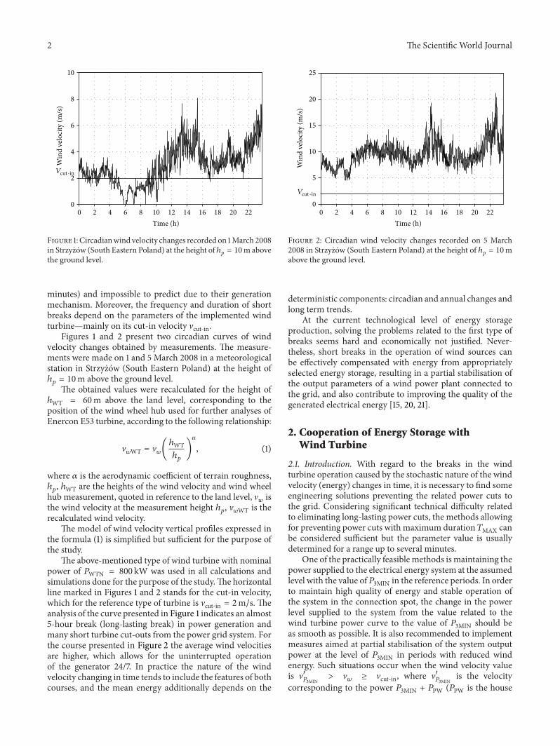
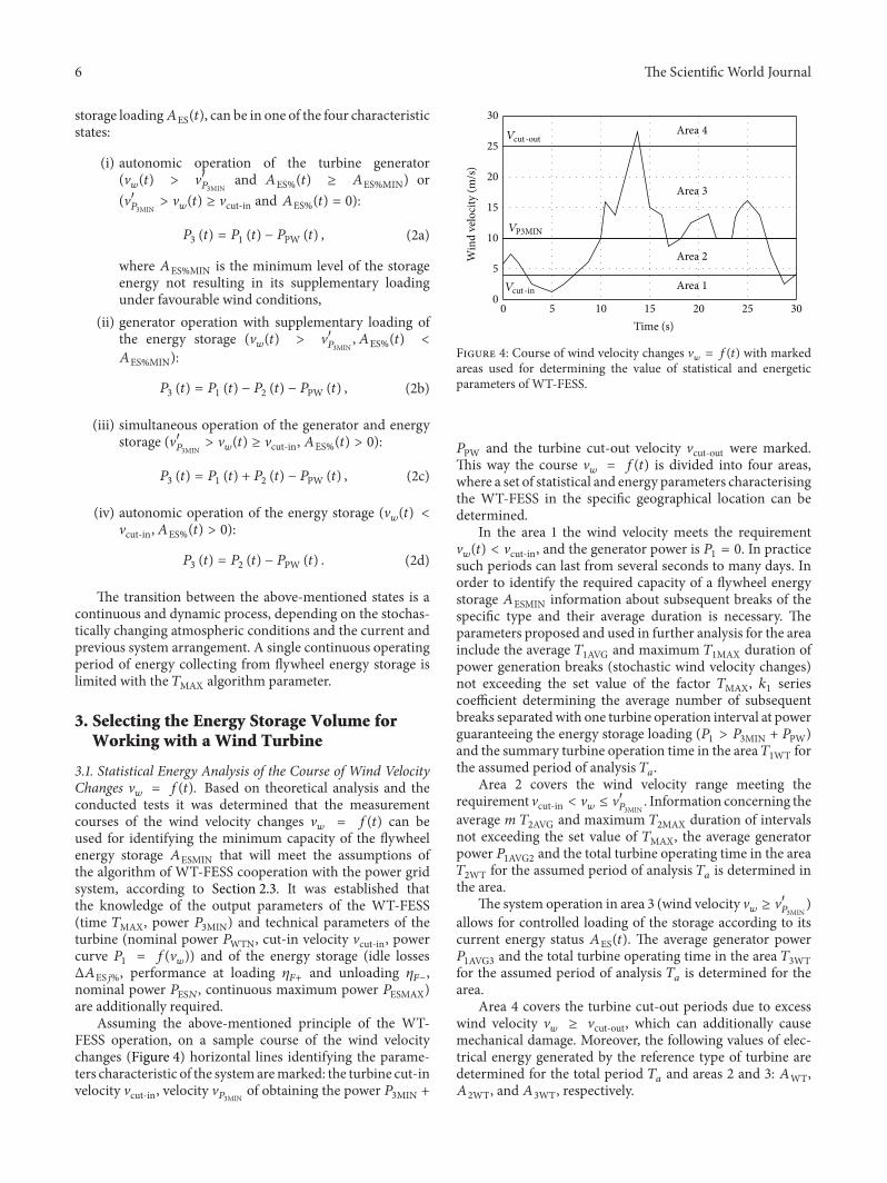
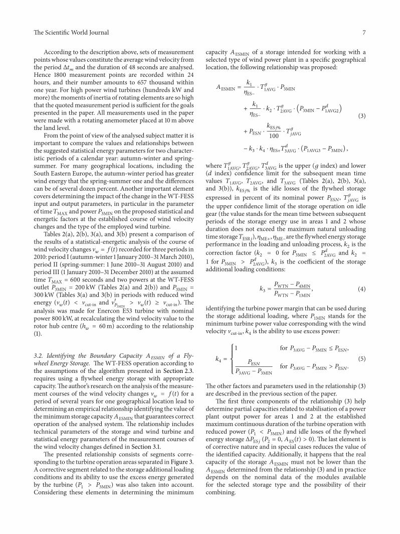
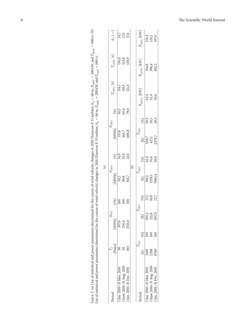
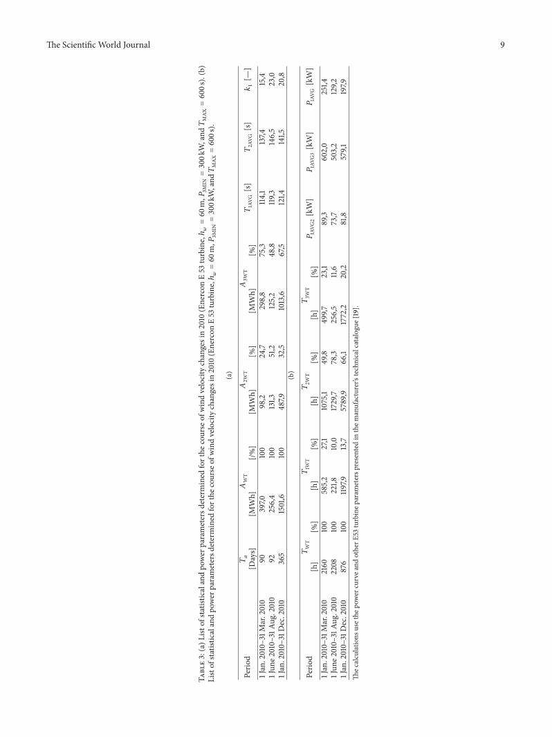
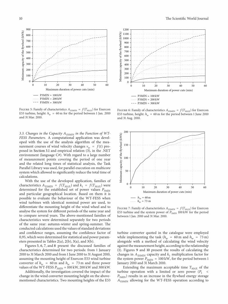
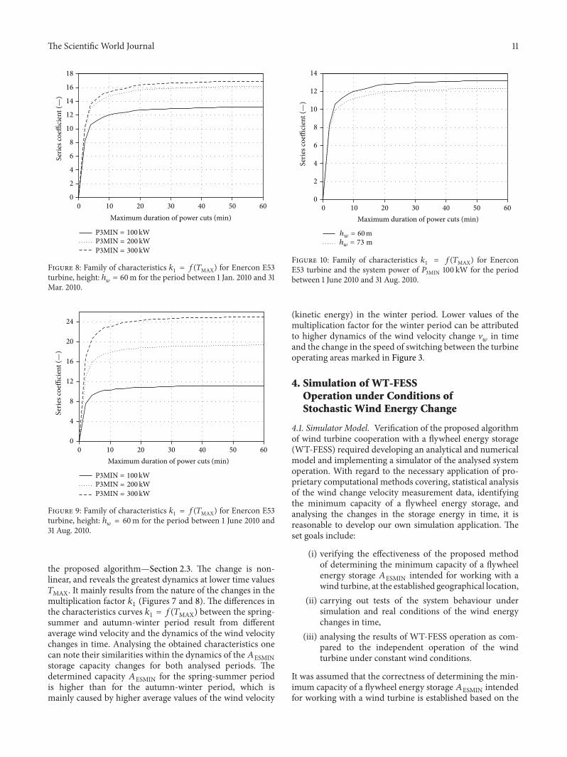
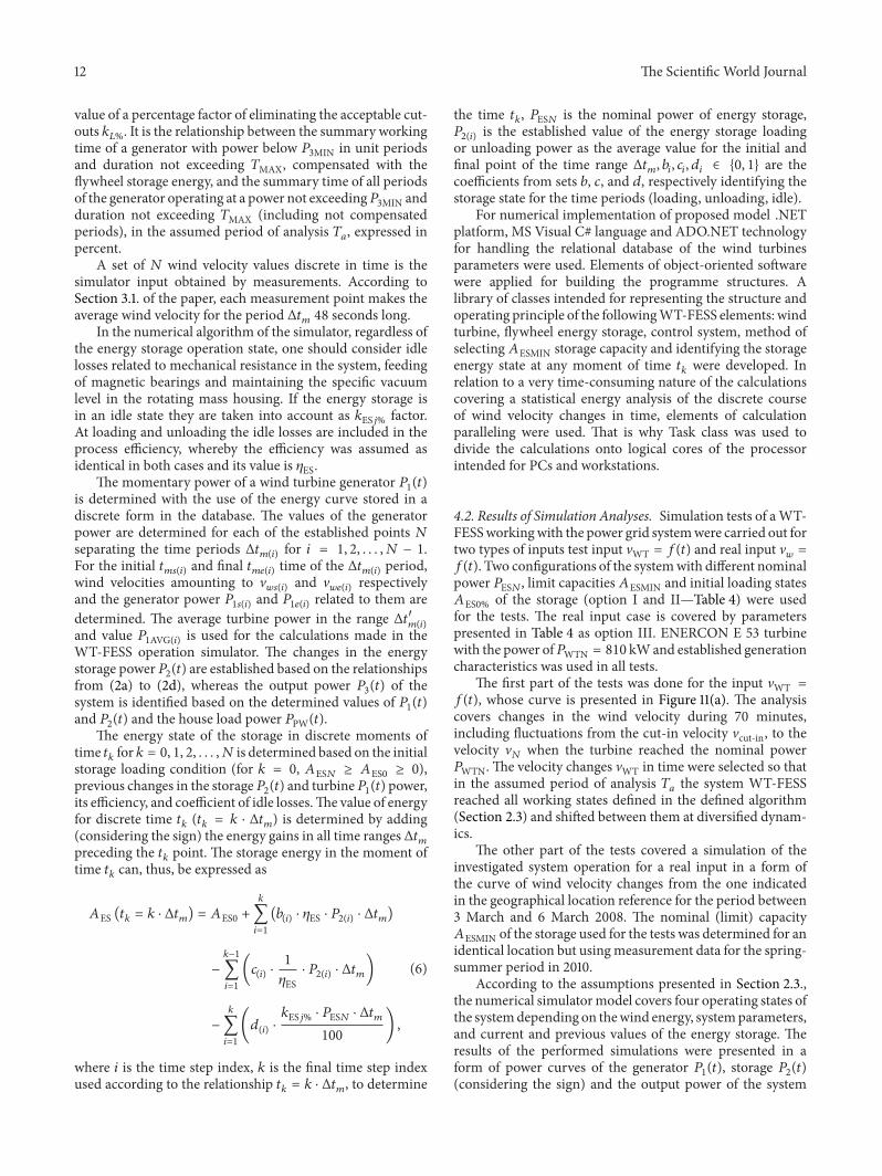