Podręcznik użytkownika - migatronic.com · 2 3 d ROBOT/PLC controller 3 vindinger gennem kerne...
70
50115061 Valid from 2019 week 06 RCI 4 Brugsvejledning User guide Betriebsanleitung Guide de l’utilisateur Guida per l’utilizzatore Gebruikershandleiding Návod k obsluze Podręcznik użytkownika
Transcript of Podręcznik użytkownika - migatronic.com · 2 3 d ROBOT/PLC controller 3 vindinger gennem kerne...

50115061 Valid from 2019 week 06
RCI4
Brugsvejledning
User guide
Betriebsanleitung
Guide de l’utilisateur
Guida per l’utilizzatore
Gebruikershandleiding
Návod k obsluze
Podręcznik użytkownika

2
Dansk ..........................................................................3
English ...................................................................... 11
Deutsch ....................................................................19
Français ....................................................................27
Italiano ......................................................................35
Nederlands ...............................................................43
Česky ........................................................................51
Polski ........................................................................59

2 3
d
ROBOT/PLCcontroller
3 vindingergennem kerne17440005
RWF 30
Sigma Select ROBO
Fjernkontrol
Fieldbuskommunikation
b
4
e
c
a
2
1
3RCI
4Anybus
ekstern
Konfigurationsfil
1
RCI4Anybus
intern
Svejseproces Afstand til arbejdsemne( + )
Total kabellængde i svejsekredsløb( + + )
Total længde af CAN kabel( + )
MIG – puls 10 m 20 m 30 m
MIG – ingen puls 30 m 60 m 30 m
cc cbd d e
Tilslutning af svejseinstallation
RCI4 Anybus
Controller
d
ROBOT/PLCcontroller
RWF 30
Sigma Select ROBO
Fjernkontrol
I/Okommunikation
b
4
e
c
a 2
3RCI I/Oekstern
4
Konfigurationsfil
1
RCI4 I/O
Kabelstørrelser
Svejsestrøm DC PULS
200 A 35 mm² 35 mm²
300 A 50 mm² 70 mm²
400 A 95 mm² / 2x50 mm² 95 mm² / 2x50 mm²
550 A 2x70 mm² 2x70 mm²
Hovedkomponenter
1. Interface
2. Svejsemaskine
3. Trådboks - RWF 30
4. Fjernbetjening
Kabler og fittings
a. Signalkabel til robot controller
b. CAN kommunikationskabel til svejsemaskine
c. Mellemkabel, gas- og 2 x svejsekabel og CAN
d. Svejsebrænder
e. Svejsereturkabel
4
Installering af Anybus-modul
RCI4 Anybus intern RCI4 Anybus ekstern
BEMÆRK:Defekte tilslutninger dækkes ikke af garantien!!!
Tilslutning af svejseinstallation
Tilslutning af RCI4 I/O ekstern
SUB D 9 pol SUB D 25 pol
Tilslutning CAN
1. Vigtigt! Indsæt stikket lige i hullet, når Anybus-modulet skal monteres.
2. Skub stikket på plads med forsigtighed og skru Anybus-modulet fast ved hjælp af skruerne.
1
22
1

4 5
MIGA_CFG
DOCUMENTS
DeviceNet
EtherCAT
PROFIBUS
PROFINET
EtherNet-IP
Config.
Konfiguration af RCI4 og robot/PLCRCI4 konfigureres med en konfigurationsfil. Valg af fil afhænger af opgave og RCI4 type (I/O eller Anybus).
Det medfølgende SD-kort indeholder diverse konfigurationsfiler samt opstillingsfiler, der er påkrævet af nogle robotter og PLC’er.
Indlæs MIGA_CFG/DOCUMENTS folderne på din PC. Hver folder indeholder EDS- eller GSD-filer, brugsanvisninger, quickguides og diverse Fieldbus moduldokumentation til kommunikationsenheder.
Indlæs MIGA.CFG/ROBOT folder på din PC for at finde information om den ønskede konfigurationsfil.
Der er følgende konfigurationsfiler til rådighed:10010208: SIGMA RCI Anybus10010210: Sigma RCI I/O, Program + process (DSUB25 only)10010211: Sigma RCI I/O, Program + sequence (DSUB25 only)10010212: Sigma RCI I/O, JOB (DSUB25 only)10010213: Sigma RCI I/O, JOB + sequence (DSUB 25+9)
Tilslutning og ibrugtagning

6
Tekniske data RCI4 I/O
ANALOG INPUTSDifferential inputs: 3
Common mode range: ± 20 VDC
Max differential voltage: 10 VDC
Differential Input impedance: 100K Ohm
Sampling frequency: 100 Hz
Max. pulse frequency (square wave): 10 Hz
Digital resolution: 10 Bit
Error: ± 2 % of reading ± 2 digits (20mV)
ANALOG OUTPUTSOutputs: 2
Maximum load: 2K Ohm
Output voltage: 0-10 V
Digital resolution: 12 Bit
Sampling frequency: 97 Hz
Error: ± 2 % of reading ± 5 digits (50mV)
Remarks: cannot be used for certification of the welding process
DIGITAL INPUTSInputs: 16
HIGH level (H): 10-26 VDC
LOW level (L): 0-3 VDC
Input impedance: 5K Ohm
Response time to input changes: 100 ms
DIGITAL OUTPUTSOutputs: 5
LOW level: <1 V
HIGH level: 20-24V from internal supply
Max load: 50 mA
Response time: 100 ms
GENERAL DATAOperating temperature: -10 to 40°C (14 to 104°F)

6 7
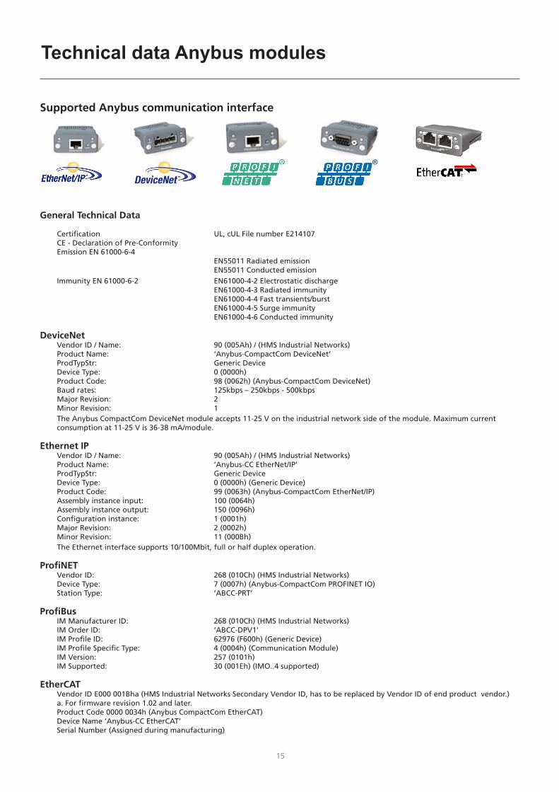
Supported Anybus communication interface
General Technical Data
Certification UL, cUL File number E214107 CE - Declaration of Pre-Conformity Emission EN 61000-6-4 EN55011 Radiated emission EN55011 Conducted emission Immunity EN 61000-6-2 EN61000-4-2 Electrostatic discharge EN61000-4-3 Radiated immunity EN61000-4-4 Fast transients/burst EN61000-4-5 Surge immunity EN61000-4-6 Conducted immunity
DeviceNet Vendor ID / Name: 90 (005Ah) / (HMS Industrial Networks) Product Name: ‘Anybus-CompactCom DeviceNet’ ProdTypStr: Generic Device Device Type: 0 (0000h) Product Code: 98 (0062h) (Anybus-CompactCom DeviceNet) Baud rates: 125kbps – 250kbps - 500kbps Major Revision: 2 Minor Revision: 1
The Anybus CompactCom DeviceNet module accepts 11-25 V on the industrial network side of the module. Maximum current consumption at 11-25 V is 36-38 mA/module.
Ethernet IP Vendor ID / Name: 90 (005Ah) / (HMS Industrial Networks) Product Name: ‘Anybus-CC EtherNet/IP’ ProdTypStr: Generic Device Device Type: 0 (0000h) (Generic Device) Product Code: 99 (0063h) (Anybus-CompactCom EtherNet/IP) Assembly instance input: 100 (0064h) Assembly instance output: 150 (0096h) Configuration instance: 1 (0001h) Major Revision: 2 (0002h) Minor Revision: 11 (000Bh)
The Ethernet interface supports 10/100Mbit, full or half duplex operation.
ProfiNET Vendor ID: 268 (010Ch) (HMS Industrial Networks) Device Type: 7 (0007h) (Anybus-CompactCom PROFINET IO) Station Type: ‘ABCC-PRT’
ProfiBus IM Manufacturer ID: 268 (010Ch) (HMS Industrial Networks) IM Order ID: ‘ABCC-DPV1’ IM Profile ID: 62976 (F600h) (Generic Device) IM Profile Specific Type: 4 (0004h) (Communication Module) IM Version: 257 (0101h) IM Supported: 30 (001Eh) (IMO..4 supported)
EtherCAT Vendor ID E000 001Bha (HMS Industrial Networks Secondary Vendor ID, has to be replaced by Vendor ID of end product vendor.) a. For firmware revision 1.02 and later. Product Code 0000 0034h (Anybus CompactCom EtherCAT) Device Name ‘Anybus-CC EtherCAT’ Serial Number (Assigned during manufacturing)
Tekniske data Anybus moduler
8
DeviceNet
# Element
1 Netværksstatus LED
2 Modulstatus LED
3 DeviceNet tilslutning
4 M12 hunstik
5 M12 hanstik
Network Status
Tilstand Indikation
Slukket Ikke online / Ingen strøm
Grøn Online, en eller flere tilslutninger etableret
Grøn, blinkende (1 Hz) Online, ingen tilslutninger etableret
Rød Kritisk linkfejl
Rød, blinkende (1 Hz) En eller flere tilslutninger på pause
Afvekslende rød/grøn Selvtest
Module Status
Tilstand Indikation
Slukket Ingen strøm
Grøn Normal drift
Grøn, blinkende(1 Hz) Manglende eller ufuldstændig konfigu-ration, enheden mangler igangsætning
Rød Fejl(ene) kan ikke udbedres
Rød, blinkende (1 Hz) Fejl(ene) kan udbedres
Afvekslende rød/grøn Selvtest
DeviceNet stikforbindelseDenne stikforbindelse sørger for forbindelse
Pin Signal Beskrivelse
1 V- Negativ bus forsyningsspænding
2 CAN_L CAN lav bus-linje
3 SHIELD Kabelbeskyttelse
4 CAN_H CAN høj bus-linje
5 V+ Positiv bus forsyningsspænding
EtherNet IP
# Element
1 Netværksstatus LED
2 Modulstatus LED
3 Link/Aktivitet
4 Ethernet Interface
Network Status LED
LED tilstand Beskrivelse
Slukket Ingen strøm eller ingen IP-adresse
Grøn Online, en eller flere tilslutninger etableret (CIP klasse 1 eller 3)
Grøn, blinkende Online, ingen tilslutninger etableret
Rød Dobbelt IP-adresse, FATAL fejl
Rød, blinkende En eller flere tilslutninger på pause (CIP Klasse 1 eller 3)
Modul Status LEDBemærk: Der udføres en testsekvens på denne LED
under opstart
LED tilstand Beskrivelse
Slukket Ingen strøm
Grøn Kontrolleret af en scanner i Run tilstand
Grøn, blinkende Ikke konfigureret, eller scanner er ikke i drift
Rød Alvorlig fejl (EXCEPTION-tilstand, FATAL fejl etc.)
Rød, blinkende Fejl, der kan udbedres
LINK/Aktivitet LED
LED tilstand Beskrivelse
Off Ingen link, ingen aktivitet
Grøn Link etableret
Grøn, flakkende Aktivitet
1 8
Anybus indikatorer

8 9
PROFIBUS
# Element
1 Driftsfunktion
2 Status
3 PROFIBUS tilslutning
4 M12 hunstik
5 M12 hanstik
Driftstilstand
Tilstand Indikation
Slukket Ikke online / Ingen strøm
Grøn Dataudveksling
Blinkende grøn Slet
Blinkende rød (1 blink) Parameterfejl
Blinkende rød (2 blink) PROFIBUS konfigurationsfejl
Status
Tilstand Indikation Bemærkninger
Slukket Ikke initialiseret Anybus tilstand = ‘OPSTILLING¨’ eller ‘NW_INIT’
Grøn Initialiseret Anybus modul har forladt ‘NW_INIT’ tilstand
Blinkende grøn Initialiseret, diagnostisk event(s) til stede
Udvidet diagnostisk bit er indstillet
Rød Fejltilstand Anybus tilstand = ‘EXCEPTION’
PROFINET IP
# Element
1 Netværksstatus LED
2 Modulstatus LED
3 Link/Aktivitet LED
4 Ethernet Interface
Netværk Status LED
Bemærk: Der udføres en testsekvens på denne LED under opstart
LED Tilstand Beskrivelse Bemærkninger
Off Offline - Ingen strøm- Ingen tilslutning med IO Controller
Grøn Online (RUN)
- Tilslutning med IO Controller etableret
- IO Controller i RUN tilstand
Grøn, blinkende
Online (STOP)
- Tilslutning med IO Controller etableret
- IO Controller i STOP tilstand
Modul Status LEDBemærk: Der udføres en testsekvens på denne LED under opstart
LED Tilstand Beskrivelse Bemærkninger
Off Ikke Initialiseret
Ingen strøm - eller - Modul i ‘OPSTILLING’ or ‘NW_INIT’ tilstand
Grøn Normal drift Modul har skiftet fra ‘NW_INIT’ tilstand
Grøn, 1 blink
Diagnostiske event(s)
Diagnostiske event(s) til stede
Grøn, 2 blink
Blink Brugt af engineering værktøjer til at identificere knude på netværk
Rød Exception-fejl Modul i tilstand ‘EXCEPTION’
Rød, 1 blink Konfigurations-fejl
Expected Identification varierer fra Real Identification
Rød, 2 blink
IP Adressefejl IP adresse ikke indstillet
Rød, 3 blink
Fejl i stations-navn
Stationsnavn ikke indstillet
Rød, 4 blink
Intern fejl Modul er stødt på en større intern fejl
LINK/Aktivitet LED
LED Tilstand Beskrivelse Bemærkninger
Slukket Ingen link Ingen link, ingen kommunikation
Grøn Link Ethernet link etableret, ingen kommunikation
Grøn, flakkende
Aktivitet Ethernet link etableret, kommunikation til stede
Ethernet InterfaceEthernet interfacet kører ved 100 Mbit, fuld duplex, med autonegotiation aktiv som standard.
1 8
Anybus indikatorer

10
EtherCATEtherCAT Connector
# Element
1 RUN LED
2 FEJL LED
3 EtherCAT (port 1)
4 EtherCAT (port 2)
5 Link/Aktivitet (port 1)
6 Link/Aktivitet (port 2)
RUN LEDDenne LED afspejler status på CoE (CANopen over EtherCAT) kommunikation
LED Tilstand Indikation Beskrivelse
Slukket INIT CoE enhed i ‘INIT’-tilstand (eller ingen strøm)
Grøn OPERATIONAL CoE enhed i ‘OPERATIONAL’-tilstand
Grøn, blinkende
PRE-OPERATIONAL
CoE enhed i ‘PRE-OPERATIONAL’-tilstand
Grøn, enkelt blink
SAFE-OPERATIONAL
CoE enhed i ‘SAFE-OPERATIONAL’-tilstand
Røda (Fatal Event) -
a. Hvis RUN og ERR bliver rød, indikerer det en fatal event, der tvinger bus interfacet til fysisk passiv tilstand. Kontakt HMS teknisk support.
ERR LEDDenne LED indikerer EtherCAT kommunikationsfejl etc.
LED Tilstand Indikation Beskrivelse
Slukket Ingen fejl Ingen fejl (eller ingen strøm)
Rød, blinkende
Ugyldig konfiguration
Tilstandsændring modtaget fra master er ikke mulig på grund af ugyldige register- eller objekt-indstillinger.
Rød, dobbelt blink
Application watchdog timeout
Sync manager watchdog timeout
Røda Application controller failure
Anybus-modul i EXCEPTION
a. Hvis RUN og ERR bliver rød, indikerer det en fatal event, der tvinger bus interfacet til fysisk passiv tilstand. Kontakt HMS teknisk support.
LINK/Aktivitet Disse LED’er indikerer EtherCAT linkstatus og aktivitet.
LED Tilstand Indikation Beskrivelse
Slukket Ingen link Link ikke registreret (eller ingen strøm)
Grøn Link registreret, ingen aktivitet
Link registreret, ingen trafik detekteret
Grøn, flakkende
Link registreret, aktivitet detekteret
Link registreret, trafik detekteret
6
Anybus indikatorer

10 11
How to connect the installation
Controller
d
ROBOT/PLCcontroller
RWF 30
Sigma Select ROBO
Remotecontrol
Fieldbuscommunication
b
4
e
c
a
2
1
3
Configuration file
1
3 windingsthrough core17440005
RCI4Anybus
external
RCI4Anybus
internal
RCI4 Anybus
Controller
d
ROBOT/PLCcontroller
RWF 30
Sigma Select ROBO
Remotecontrol
I/Ocommunication
b
4
e
c
a 2
3RCI I/Oexternal
4
Configuration file
1
RCI4 I/O
Welding process Distance to work piece( + )
Total cable length in welding circuit( + + )
Total length of CAN cable( + )
MIG – pulse 10 m 20 m 30 m
MIG – non pulse 30 m 60 m 30 m
cc cbd d e
Cable dimensions
Welding current DC PULSE
200 A 35 mm² 35 mm²
300 A 50 mm² 70 mm²
400 A 95 mm² / 2x50 mm² 95 mm² / 2x50 mm²
550 A 2x70 mm² 2x70 mm²
Main components
1. Interface
2. Welding machine
3. Wire feed unit - RWF 30
4. Remote control
Kabler og fittings
a. Signal cable for robot controller
b. CAN communication cable for welding machine
c. Interconnection, gas and 2xwelding cable and CAN
d. Welding torch
e. Welding return cable

12
How to connect the installation
NOTE:Defective connectors Are not covered by warranty!!!
Installing the Anybus module
RCI4 Anybus internal RCI4 Anybus external
1
22
1
Connecting the RCI4 I/O External
SUB D 9 pol SUB D 25 pol
CAN connection
1. Important! Once you have installed the Anybus module, insert the plug straight into the hole.
2. Press the plug slightly into position and tighten the Anybus module using the screws.

12 13
Connection and operation
MIGA_CFG
DOCUMENTS
DeviceNet
EtherCAT
PROFIBUS
PROFINET
EtherNet-IP
Config.
Configuring the RCI4 and Robot/PLCUse a configuration file to configure RCI4. Choose file type according to assignment and RCI4 type (I/O or Anybus).
The SD card included in the supply contains various configuration files and setup files required by some robots and PLCs.
Load the MIGA_CFG/DOCUMENTS folders on your PC. Each folder contains EDS or GSD files, user manuals, quick guides and various Fieldbus module documentation for communication devices.
Load MIGA.CFG/ROBOT folder on your PC to find information about the desired configuration file.
The following configuration files are available:10010208: SIGMA RCI Anybus10010210: Sigma RCI I/O, Program + process (DSUB25 only)10010211: Sigma RCI I/O, Program + sequence (DSUB25 only)10010212: Sigma RCI I/O, JOB (DSUB25 only)10010213: Sigma RCI I/O, JOB + sequence (DSUB 25+9)

14
Technical data RCI4 I/O
ANALOG INPUTSDifferential inputs: 3
Common mode range: ± 20 VDC
Max differential voltage: 10 VDC
Differential Input impedance: 100K Ohm
Sampling frequency: 100 Hz
Max. pulse frequency (square wave): 10 Hz
Digital resolution: 10 Bit
Error: ± 2 % of reading ± 2 digits (20mV)
ANALOG OUTPUTSOutputs: 2
Maximum load: 2K Ohm
Output voltage: 0-10 V
Digital resolution: 12 Bit
Sampling frequency: 97 Hz
Error: ± 2 % of reading ± 5 digits (50mV)
Remarks: cannot be used for certification of the welding process
DIGITAL INPUTSInputs: 16
HIGH level (H): 10-26 VDC
LOW level (L): 0-3 VDC
Input impedance: 5K Ohm
Response time to input changes: 100 ms
DIGITAL OUTPUTSOutputs: 5
LOW level: <1 V
HIGH level: 20-24V from internal supply
Max load: 50 mA
Response time: 100 ms
GENERAL DATAOperating temperature: -10 to 40°C (14 to 104°F)
14 15
Supported Anybus communication interface
General Technical Data
Certification UL, cUL File number E214107 CE - Declaration of Pre-Conformity Emission EN 61000-6-4 EN55011 Radiated emission EN55011 Conducted emission Immunity EN 61000-6-2 EN61000-4-2 Electrostatic discharge EN61000-4-3 Radiated immunity EN61000-4-4 Fast transients/burst EN61000-4-5 Surge immunity EN61000-4-6 Conducted immunity
DeviceNet Vendor ID / Name: 90 (005Ah) / (HMS Industrial Networks) Product Name: ‘Anybus-CompactCom DeviceNet’ ProdTypStr: Generic Device Device Type: 0 (0000h) Product Code: 98 (0062h) (Anybus-CompactCom DeviceNet) Baud rates: 125kbps – 250kbps - 500kbps Major Revision: 2 Minor Revision: 1
The Anybus CompactCom DeviceNet module accepts 11-25 V on the industrial network side of the module. Maximum current consumption at 11-25 V is 36-38 mA/module.
Ethernet IP Vendor ID / Name: 90 (005Ah) / (HMS Industrial Networks) Product Name: ‘Anybus-CC EtherNet/IP’ ProdTypStr: Generic Device Device Type: 0 (0000h) (Generic Device) Product Code: 99 (0063h) (Anybus-CompactCom EtherNet/IP) Assembly instance input: 100 (0064h) Assembly instance output: 150 (0096h) Configuration instance: 1 (0001h) Major Revision: 2 (0002h) Minor Revision: 11 (000Bh)
The Ethernet interface supports 10/100Mbit, full or half duplex operation.
ProfiNET Vendor ID: 268 (010Ch) (HMS Industrial Networks) Device Type: 7 (0007h) (Anybus-CompactCom PROFINET IO) Station Type: ‘ABCC-PRT’
ProfiBus IM Manufacturer ID: 268 (010Ch) (HMS Industrial Networks) IM Order ID: ‘ABCC-DPV1’ IM Profile ID: 62976 (F600h) (Generic Device) IM Profile Specific Type: 4 (0004h) (Communication Module) IM Version: 257 (0101h) IM Supported: 30 (001Eh) (IMO..4 supported)
EtherCAT Vendor ID E000 001Bha (HMS Industrial Networks Secondary Vendor ID, has to be replaced by Vendor ID of end product vendor.) a. For firmware revision 1.02 and later. Product Code 0000 0034h (Anybus CompactCom EtherCAT) Device Name ‘Anybus-CC EtherCAT’ Serial Number (Assigned during manufacturing)
Technical data Anybus modules

16
EtherNet IP
# Item
1 Network status LED
2 Module status LED
3 Link/Activity
4 Ethernet Interface
Network Status LED
LED State Description
Off No power or no IP address
Green On-line, one or more connections established (CIP Class 1 or 3)
Green, flashing On-line, no connections established
Red Duplicate IP address, FATAL error
Red, flashing One or more connections timed out (CIP Class 1 or 3)
Module Status LEDNote: A test sequence is performed on this LED during startup
LED State Description
Off No power
Green Controlled by a Scanner in Run state
Green, flashing Not configured, or Scanner in Idle state
Red Major fault (EXCEPTION-state, FATAL error etc.)
Red, flashing Recoverable Fault(s)
LINK/Activity LED
LED State Description
Off No link, no activity
Green Link established
Green, flickering Activity
1 8
DeviceNet
# Item
1 Network status LED
2 Module status LED
3 DeviceNet connector
4 M12 Female connector
5 M12 Male connector
Network Status
State Indication
Off Not online / No power
Green On-line, one or more connections are established
Flashing Green (1 Hz) On-line, no connections established
Red Critical link failure
Flashing Red (1 Hz) One or more connections timed-out
Alternating Red/Green
Self test
Module Status
State Indication
Off No power
Green Operating in normal condition
Flashing Green (1 Hz) Missing or incomplete configuration, device needs commissioning
Red Unrecoverable Fault(s)
Flashing Red (1 Hz) Recoverable Fault(s)
Alternating Red/Green
Self test
DeviceNet ConnectorThis connector provides DeviceNet connectivity
Pin Signal Description
1 V- Negative bus supply voltage
2 CAN_L CAN low bus line
3 SHIELD Cable shield
4 CAN_H CAN high bus line
5 V+ Positive bus supply voltage
Anybus indicators

16 17
PROFIBUS
# Item
1 Operation Mode
2 Status
3 PROFIBUS Connector
4 M12 Female Connector
5 M12 Male connector
Operation Mode
State Indication
Off Not online / No power
Green Data exchange
Flashing Green Clear
Flashing Red (1 flash) Parametrization error
Flashing Red (2 flashes) PROFIBUS Configuration error
Status
State Indication Comments
Off Not initialized Anybus state = ‘SETUP¨’ or ‘NW_INIT’
Green Initialized Anybus module has left the ‘NW_INIT’ state
Flashing Green Initialized, diagnostic event(s) present
Extended diagnostic bit is set
Red Exception error Anybus state = ‘EXCEPTION’
PROFINET IP
# Item
1 Network status LED
2 Module status LED
3 Link/Activity LED
4 Ethernet Interface
Network Status LED
Note: A test sequence is performed on this LED during startup
LED State Description Comments
Off Offline - No power- No connection with IO Controller
Green Online (RUN)
- Connection with IO Controller established
- IO Controller in RUN state
Green, flashing
Online (STOP)
- Connection with IO Controller established
- IO Controller in STOP state
Module Status LEDNote: A test sequence is performed on this LED during startup
LED State Description Comments
Off Not Initialized No power - or - Module in ‘SETUP’ or ‘NW_INIT’ state
Green Normal Operation
Module has shifted from the ‘NW_INIT’ state
Green, 1 flash
Diagnostic Event(s)
Diagnostic event(s) present
Green, 2 flashes
Blink Used by engineering tools to identify the node on the network
Red Exception Error Module in state ‘EXCEPTION’
Red, 1 flash Configuration Error
Expected Identification differs from Real Identification
Red, 2 flashes
IP Address Error IP address not set
Red, 3 flashes
Station Name Error
Station Name not set
Red, 4 flashes
Internal Error Module has encountered a major internal error
LINK/Activity LED
LED State Description Comments
Off No link No link, no communication present
Green Link Ethernet link established, no communication present
Green, flickering
Activity Ethernet link established, communication present
Ethernet InterfaceThe Ethernet interface operates at 100 Mbit, full duplex, with autonegotiation enabled as default.
1 8
Anybus indicators

18
EtherCATEtherCAT Connector
# Item
1 RUN LED
2 ERROR LED
3 EtherCAT (port 1)
4 EtherCAT (port 2)
5 Link/Activity (port 1)
6 Link/Activity (port 2)
RUN LEDThis LED reflects the status of the CoE (CANopen over EtherCAT) communication
LED State Indication Description
Off INIT CoE device in ‘INIT’-state (or no power)
Green OPERATIONAL CoE device in ‘OPERATIONAL’-state
Green, blinking
PRE-OPERATIONAL
CoE device in ‘PRE-OPERATIONAL’-state
Green, single flash
SAFE-OPERATIONAL
CoE device in ‘SAFE-OPERATIONAL’-state
Reda (Fatal Event) -
a. If RUN and ERR turns red, this indicates a fatal event, forcing the bus interface to a physically passive state. Contact HMS technical support
ERR LEDThis LED indicates EtherCAT communication errors etc.
LED State Indication Description
Off No error No error (or no power)
Red, blinking
Invalid configuration
State change received from master is not possible due to invalid register or object settings
Red, double flash
Application watchdog timeout
Sync manager watchdog timeout
Reda Application controller failure
Anybus module in EXCEPTION
a. If RUN and ERR turns red, this indicates a fatal event, forcing the bus interface to a physically passive state. Contact HMS technical support
LINK/Activity These LEDs indicate the EtherCAT link status and activity
LED State Indication Description
Off No link Link not sensed (or no power)
Green Link sensed, no activity
Link sensed, no traffic detected
Green, flickering
Link sensed, activity detected
Link sensed, traffic detected
6
Anybus indicators

18 19
Anschluss der Anlage
3 Wicklungendurch Kern17440005
Controller
d
ROBOTER/PLCcontroller
RWF 30
Sigma Select ROBO
Fernregler
FieldbusKommunikation
b
4
e
c
a
2
1
3
Konfigurations-datei
1
RCI4Anybus
extern
RCI4Anybus
intern
RCI4 Anybus
Controller
d
ROBOTER/PLCcontroller
RWF 30
Sigma Select ROBO
Fernregler
I/OKommunikation
b
4
e
c
a 2
3 RCI I/Oextern
4
1
Konfigurations-datei
RCI4 I/O
Schweißprozess Abstand zum Werkstück( + )
Gesamtlänge des Kabels im Schweißstromkreis( + + )
Gesamtlänge des CAN-Kabels( + )
MIG – Puls 10 m 20 m 30 m
MIG – kein Puls 30 m 60 m 30 m
cc cbd d e
Kabelgrößen
Schweißstrom DC PULS
200 A 35 mm² 35 mm²
300 A 50 mm² 70 mm²
400 A 95 mm² / 2x50 mm² 95 mm² / 2x50 mm²
550 A 2x70 mm² 2x70 mm²
Hauptkomponenten
1. Interface
2. Schweißmachine
3. Drahtvorschubeinheit - RWF 30
4. Fernregler
Kabel und Fittings
a. Signalkabel für Robotersteuerung
b. CAN Kommunikationskabel für Schweißmachine
c. Zwischenschlauchpaket, Gas- und 2xSchweißkabel und CAN
d. Schweißbrenner
e. Schweißrückleitungskabel
20
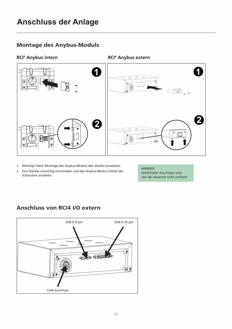
HINWEIS:Fehlerhafte Anschlüsse sind von der Garantie nicht umfasst!
Anschluss der Anlage
Montage des Anybus-Moduls
RCI4 Anybus intern RCI4 Anybus extern
Anschluss von RCI4 I/O extern
SUB D 9 pol SUB D 25 pol
CAN-Anschluss
1. Wichtig!! Nach Montage des Anybus-Moduls den Stecker einsetzen.
2. Den Stecker vorsichtig einschieben und das Anybus-Modul mittels der Schrauben anziehen.
1
22
1

20 21
MIGA_CFG
DOCUMENTS
DeviceNet
EtherCAT
PROFIBUS
PROFINET
EtherNet-IP
Config.
Konfiguration von RCI4 und Roboter/PLCRCI4 ist mittels einer Konfigurationsdatei zu konfigurieren. Wählen Sie die Datei je nach Aufgabe und RCI4 Typ (I/O bzw. Anybus).
Die SD-Karte gehört zum Lieferumfang und enthält verschiedene Konfigurationsdateien sowie Installationsdateien, die für einige Roboter und SPS notwendig sind.
Die MIGA_CFG/DOCUMENTS-Ordner auf Ihren PC laden. Jeder Ordner enthält EDS- bzw. GSD-Dateien, Betriebsanleitungen, Kurzanleitungen und verschiedene Fieldbus Moduldokumentation für Kommunikationsgeräte.
MIGA.CFG/ROBOT auf Ihren PC laden. Information über die gewünschte Konfigurationsdatei entnehmen Sie dem Ordner.
Verfügbar sind folgende Konfigurationsdateien:10010208: SIGMA RCI Anybus10010210: Sigma RCI I/O, Program + process (DSUB25 only)10010211: Sigma RCI I/O, Program + sequence (DSUB25 only)10010212: Sigma RCI I/O, JOB (DSUB25 only)10010213: Sigma RCI I/O, JOB + sequence (DSUB 25+9)
Anschluss und Inbetriebnahme

22
Technische Daten RCI4 I/O
ANALOGEINGÄNGEDifferentiale Eingänge: 3
Gleichtaktbereich: ± 20 VDC
Max. differentiale Spannung: 10 VDC
Differentiale Eingangsimpedanz: 100K Ohm
Samplingfrequenz: 100 Hz
Höchst-Pulsfrequenz (Rechteck): 10 Hz
Digitale Auslösung: 10 Bit
Fehler: ± 2 % des Messwertes ± 2 Ziffer (20mV)
ANALOGAUSGÄNGEAusgänge: 2
Höchstbelastung: 2K Ohm
Ausgangsspannung: 0-10 V
Digitale Auflösung: 12 Bit
Samplingfrequenz: 97 Hz
Fehler: ± 2 % des Messwertes ± 5 Ziffer (50mV)
Hinweis: nicht einsetzbar für Zertifizierung des Schweißprozesses
DIGITALEINGÄNGEEingänge: 16
HOHES Niveau (H): 10-26 VDC
NIEDRIGES Niveau (L): 0-3 VDC
Eingangsimpedanz: 5K Ohm
Reaktionszeit zu Eingangsänderungen: 100 ms
DIGITALAUSGÄNGEAusgänge: 5
NIEDRIGES Niveau: <1 V
HOHES Niveau: 20-24V von der internen Versorgung
Höchstbelastung: 50 mA
Reaktionszeit: 100 ms
ALLGEMEINE DATENBetriebstemperatur: -10 bis 40°C (14 bis 104°F)

22 23
Unterstützte Anybus Kommunikation Interfaces
Allgemeine Technische Daten
Certification UL, cUL File number E214107 CE - Declaration of Pre-Conformity Emission EN 61000-6-4 EN55011 Radiated emission EN55011 Conducted emission Immunity EN 61000-6-2 EN61000-4-2 Electrostatic discharge EN61000-4-3 Radiated immunity EN61000-4-4 Fast transients/burst EN61000-4-5 Surge immunity EN61000-4-6 Conducted immunity
DeviceNet Anbieter ID / Name: 90 (005Ah) / (HMS Industrial Networks) Produktname: ‘Anybus-CompactCom DeviceNet’ ProdTypStr: Generic Device Device Type: 0 (0000h) Product Code: 98 (0062h) (Anybus-CompactCom DeviceNet) Baud rates: 125kbps – 250kbps - 500kbps Major Revision: 2 Minor Revision: 1
The Anybus CompactCom DeviceNet module accepts 11-25 V on the industrial network side of the module. Höchststromverbrauch bei 11-25 V: 36-38 mA/Modul.
Ethernet IP Anbieter ID / Name: 90 (005Ah) / (HMS Industrial Networks) Produktname: ‘Anybus-CC EtherNet/IP’ ProdTypStr: Generic Device Device Type: 0 (0000h) (Generic Device) Product Code: 99 (0063h) (Anybus-CompactCom EtherNet/IP) Assembly instance Eingang: 100 (0064h) Assembly instance Ausgang: 150 (0096h) Konfigurations instance: 1 (0001h) Major Revision: 2 (0002h) Minor Revision: 11 (000Bh)
Ethernet interface unterstützt 10/100Mbit, full or half duplex operation.
ProfiNET Anbieter ID: 268 (010Ch) (HMS Industrial Networks) Device Type: 7 (0007h) (Anybus-CompactCom PROFINET IO) Station Type: ‘ABCC-PRT’
ProfiBus IM Manufacturer ID: 268 (010Ch) (HMS Industrial Networks) IM Order ID: ‘ABCC-DPV1’ IM Profile ID: 62976 (F600h) (Generic Device) IM Profile Specific Type: 4 (0004h) (Kommunikation Modul) IM Version: 257 (0101h) IM Supported: 30 (001Eh) (IMO..4 unterstützt)
EtherCAT Anbieter ID E000 001Bha (HMS Industrial Networks Secondary Anbieter ID, muss durch Anbieter ID des Endprodukt-Anbieters ersetzt werden.) a. Für Firmware-Revision 1.02 und später. Product Code 0000 0034h (Anybus CompactCom EtherCAT) Device Name ‘Anybus-CC EtherCAT’ Serial Number (Assigned during manufacturing)
Technische Daten Anybus-Moduls

24
EtherNet IP
# Artikel
1 Netzwerkstatus LED
2 Modulstatus LED
3 Link/Aktivität
4 Ethernet Interface
Netzwerk-Status LED
LED Zustand Beschreibung
AUS Keine Stromversorgung bzw. keine IP-Adresse
Grün On-line, ein Anschluss bzw. mehrere Anschlüsse ist/sind etabliert (CIP Klasse 1 oder 3)
Grün, blinkend On-line, kein Anschluss etabliert
Rot Doppelte IP Adresse, FATALER Fehler
Rot, blinkend Ein Anschluss oder mehrere Anschlüsse ist/sind abgebrochen (CIP Klasse 1 oder 3)
Modul-Status LEDHinweis: Bei der Inbetriebnahme eine Testsequenz auf diese LED ausführen
LED Zustand Beschreibung
AUS Keine Stromversorgung
Grün Gesteuert durch einen Scanner in Laufzustand
Grün, blinkend Nicht konfiguriert bzw. Scanner in Leerlaufzustand
Rot Großer Fehler (Ausnahme-Zustand, fataler Fehler etc.)
Rot, blinkend Behebbare(r) Fehler
LINK/Aktivität LED
LED Zustand Beschreibung
AUS Kein Link, keine Aktivität
Grün Link etabliert
Grün, blinkend Aktivität
1 8
DeviceNet
# Artikel
1 Netzwerkstatus LED
2 Modulstatus LED
3 DeviceNet Anschluss
4 M12 Weiblicher Anschluss
5 M12 Männlicher Anschluss
Netzwerkstatus
Zustand Anzeige
AUS Nicht online / Keine Stromversorgung
Grün Online, eine oder mehrere Anschlüsse hergestellt
Grün blinkend (1 Hz) Online, kein Anschluss
Rot Kritischer Verbindungsfehler
Rot blinkend (1 Hz) Eine oder mehrere Anschlüsse unterbrochen
Wechselnd rot/grün Selbsttest
Modulstatus
Zustand Anzeige
AUS Keine Stromversorgung
Grün Normalbetrieb
Grün blinkend (1 Hz) Fehlende bzw. unvollständige Konfiguration, Inbetriebenahme nötig
Rot Nicht behebbare(r) Fehler
Rot blinkend (1 Hz) Behebbare(r) Fehler
Wechselnd rot/grün Selbsttest
DeviceNet-AnschlussDieser Anschluss stellt DeviceNet-Konnektivität zur Verfügung
Stift Signal Beschreibung
1 V- Negative bus-Versorgung Spannung
2 CAN_L CAN niedrige bus-Linie
3 SHIELD Kabelschutz
4 CAN_H CAN hohe bus-Linie
5 V+ Positive bus-Versorgung Spannung
Anybus Indikatoren

24 25
PROFIBUS
# Artikel
1 Betriebsmodus
2 Status
3 PROFIBUS Anschluss
4 M12 Weiblicher Anschluss
5 M12 Männlicher Anschluss
Operation Mode
Zustand Anzeige
AUS Nicht online / Keine Stromversorgung
Grün Datenaustausche
Grün, blinkend Löschen
Rot, blinkend (1 Blitz) Parametrisationsfehler
Rot, blinkend (2 Blitze) PROFIBUS Konfigurationsfehler
Status
Zustand Anzeige Bemerkungen
AUS Nicht initialisiert Anybus Zustand = ‘INSTALLATION¨’ bzw. ‘NW_INIT’
Grün Initialisiert Anybus Modul hat den ‘NW_INIT’ Zustand verlassen
Grün, blinkend Initialisiert, Diagnostik Ereigniss(e) vorhanden
Erweitertes Diagnostik-Bit eingestellt
Rot Ausnahmefehler Anybus Zustand = ‘EXCEPTION’
PROFINET IP
# Artikel
1 Netzwerk-Status LED
2 Modul-Status LED
3 Link/Aktivität LED
4 Ethernet Interface
Netzwerk Status LED
Hinweis: Bei der Inbetriebnahme eine Testsequenz auf diese LED ausführen
LED Zustand Beschreibung Bemerkungen
AUS Offline - Keine Stromversorgung- Kein Anschluss mit IO Controller
Grün Online (RUN) - Anschluss mit IO Controller etabliert
- IO Controller in RUN Zustand
Blinkend grün
Online (STOP) - Anschluss mit IO Controller etabliert
- IO Controller in STOP Zustand
Modul Status LEDHinweis: Bei der Inbetriebnahme eine Testsequenz auf diese LED ausführen
LED Zustand Beschreibung Bemerkungen
AUS Nicht initialisiert
Keine Stromversorgung bzw. Modul in ‘INSTALLATION’ oder ‘NW_INIT’ Zustand
Grün Normale Funktion
Modul hat von ‘NW_INIT’ Zustand geändert
Grün, 1 Blitz
Diagnostik Ereigniss(e)
Diagnostik Ereigniss(e) vorhanden
Grün, 2 Blitze
Blink Von Engineering Werkzeugen gebraucht zur Identifizierung des Netzwerksknotens
Rot Ausnahme-fehler
Modul in ‘EXCEPTION’ Zustand
Rot, 1 Blitz Konfigurations-fehler
Erwartete Identifikation unterscheidet sich von der Realen Identifikation
Rot, 2 Blitze IP-Adresse-fehler
IP Adresse nicht eingestellt
Rot, 3 Blitze Stationsname-fehler
Stationsname nicht eingestellt
Rot, 4 Blitze Interner Fehler Modul hat einen großen internen Fehler getroffen
LINK/Aktivität LED
LED Zustand Beschreibung Bemerkungen
AUS Kein Link Kein Link, keine Kommunikation
Grün Link Ethernet Link etabliert, keine Kommunikation
Grün, blinkend
Aktivität Ethernet Link etabliert, Kommunikation vorhanden
Ethernet InterfaceDas Ethernet Interface funktioniert bei 100 Mbit, Full Duplex, mit Autonegotiation standardmäßig aktiviert.
1 8
Anybus Indikatoren

26
EtherCATEtherCAT Anschluss
# Artikel
1 RUN LED
2 FEHLER LED
3 EtherCAT (port 1)
4 EtherCAT (port 2)
5 Link/Aktivität (Port 1)
6 Link/Aktivität (Port 2)
RUN LEDDiese LED zeigt CoE (CANopen over EtherCAT) Kommunikation-Status an
LED Zustand Anzeige Beschreibung
AUS INIT CoE Gerät in ‘INIT’-Zustand (bzw. keine Stromversorgung)
Grün OPERATIONAL CoE Gerät in ‘OPERATIONAL’-Zustand
Grün, blinking
PRE-OPERATIONAL
CoE Gerät in ‘PRE-OPERATIONAL’-Zustand
Grün, einzel-blinkend
SAFE-OPERATIONAL
CoE Gerät in ‘SAFE-OPERATIONAL’-Zustand
Rota (Fatales Ereignis) -
a. Rote RUN und ERR LEDS zeigen ein fatales Ereignis an, das das BUS-Interface in einem physisch passiven Zustand zwingt. HMS Technischer Support kontaktieren.
ERR LEDDiese LED zeigt EtherCAT Kommunikationsfehler etc. an
LED Zustand Anzeige Beschreibung
AUS Kein Fehler Kein Fehler bzw. keine Stromversorgung
Rot, blinkend
Ungültige Konfiguration
Zustandswechsel vom Master empfangen ist nicht möglich aufgrund üngültiger Register bzw. Objekteinstellungen
Rot, doppel-blinkend
Application Watchdog Timeout
Sync Manager Watchdog Timeout
Rota Application Con-troller Fehler
Anybus Modul in EXCEPTION
a. Rote RUN und ERR LEDS zeigen ein fatales Ereignis an, das das BUS-Interface in einem physisch passiven Zustand zwingt. HMS Technischer Support kontaktieren.
LINK/AktivitätDiese LEDs zeigen EtherCAT Linkstatus und Aktivität an
LED Zustand Anzeige Beschreibung
AUS Kein Link Link nicht gefühlt (bzw. keine Stromversorgung)
Grün Link gefühlt, keine Aktivität
Link gefühlt, kein Trafik festgestellt
Grün, blinkend
Link gefühlt, Aktivität festgestellt
Link gefühlt, Trafik festgestellt
6
Anybus Indikatoren

26 27
Raccordement de l’installation
d
RWF 30
Sigma Select ROBO
Télécommande
b
4
e
c
a
2
1
3
Fichier deconfiguration
1
ContrôleurROBOT/API
Contrôleur
CommunicationFieldbus
3 enroulementsautour du noyau17440005
RCI4Anybus
externe
RCI4Anybus
interne
RCI4 Anybus
d
RWF 30
Sigma Select ROBO
CommunicationE/S
b
4
e
c
a 2
3 E/S RCIexterne
4
1
ContrôleurROBOT/API
Contrôleur
Télécommande
Fichier deconfiguration
RCI4 E/S
Procédé de soudage Distance par rapport à la pièce( + )
Longueur totale du câble dans le circuit de soudage( + + )
Longueur totale du câble CAN( + )
MIG - pulsé 10 m 20 m 30 m
MIG - non pulsé 30 m 60 m 30 m
cc cbd d e
Dimensions de câble
Courant de soudage Courant Continu Pulsé
200 A 35 mm² 35 mm²
300 A 50 mm² 70 mm²
400 A 95 mm² / 2x50 mm² 95 mm² / 2x50 mm²
550 A 2x70 mm² 2x70 mm²
Composants principaux
1. Interface
2. Machine de soudage
3. Dévidoir - RWF 30
4. Commande à distance
Câbles et raccords
a. Câble de signal pour unité de commande robot
b. Câble de communication CAN pour machine de soudage
c. Interconnexion, gaz, 2 câbles soudage et CAN
d. Torche de soudage
e. Câble de retour soudage

28
REMARQUE :Les connecteurs défectueux ne sont pas pris en charge par la garantie !
Raccordement de l’installation
Installation du module Anybus
Anybus RCI4 interne Anybus RCI4 externe
Connexion d’E/S RCI4 externe
SUB D 9 pol SUB D 25 pol
Raccordement CAN
1. Important ! Une fois le module Anybus installé, insérez la fiche dans l’emplacement prévu à cet effet.
2. Appliquez une légère pression pour le maintenir en position et fixez le module Anybus à l’aide des vis.
1
22
1

28 29
Branchement et fonctionnement
MIGA_CFG
DOCUMENTS
DeviceNet
EtherCAT
PROFIBUS
PROFINET
EtherNet-IP
Config.
Configuration de l’interface RCI4 et du robot/de l’APIUtilisez un fichier de configuration pour configurer l’interface RCI4. Sélectionnez le type de fichier en fonction de l’opération et du type d’interface RCI4 (E/S ou Anybus).
La carte SD fournie contient différents fichiers de configuration et d’installation requis par certains robots et API.
Chargez le dossier MIGA_CFG/DOCUMENTS et ses sous-dossiers sur votre ordinateur. Chaque dossier contient des fichiers EDS ou GSD, des manuels utilisateur, des guides rapides ainsi que de la documentation relative au module Fieldbus pour les dispositifs de communication.
Chargez le dossier MIGA.CFG/ROBOT sur votre ordinateur pour trouver des informations sur le fichier de configuration souhaité.
Les fichiers de configuration suivants sont disponibles :10010208 : Anybus RCI SIGMA10010210 : E/S RCI Sigma, programme + processus (DSUB25 seulement)10010211 : E/S RCI Sigma, programme + séquence (DSUB25 seulement)10010212 : E/S RCI Sigma, tâche (DSUB25 seulement)10010213 : E/S RCI Sigma, tâche + séquence (DSUB 25+9)

30
Caractéristiques techniques d’E/S de l’interface RCI4
ENTRÉES ANALOGIQUESEntrées différentielles : 3
Plage de mode commun : ± 20 Vcc
Tension différentielle max. : 10 Vcc
Impédance d’entrée différentielle : 100 k Ohm
Fréquence d’échantillonnage : 100 Hz
Fréquence d’impulsion max. (onde carrée) : 10 Hz
Résolution numérique : 10 bits
Erreur : ± 2 % de la lecture ± 2 chiffres (20 mV)
SORTIES ANALOGIQUESSorties : 2
Charge maximale : 2 k Ohm
Tension de sortie : 0-10 V
Résolution numérique : 12 bits
Fréquence d’échantillonnage : 97 Hz
Erreur : ± 2 % de la lecture ± 5 chiffres (50 mV)
Remarque : ne peut pas être utilisé pour la certification du procédé de soudage
ENTRÉES NUMÉRIQUESEntrées : 16
Niveau élevé (H) : 10-26 Vcc
Niveau bas (L) : 0-3 Vcc
Impédance d’entrée : 5 k Ohm
Délai de réponse aux changements d’entrée : 100 ms
SORTIES NUMÉRIQUESSorties : 5
Niveau bas : < 1 V
Niveau élevé : 20-24 V de l’alimentation interne
Charge max. : 50 mA
Délai de réponse : 100 ms
DONNÉES GÉNÉRALESTempérature de fonctionnement : -10 à 40 °C (14 à 104 °F)

30 31
Interface de communication Anybus prise en charge
Données techniques générales
Certification UL, cUL ; numéro de fichier E CE - Déclaration de pré-conformité Émissions EN 61000-6-4 EN55011 Émissions rayonnées EN55011 Émissions par conduction Immunité EN 61000-6-2 EN61000-4-2 Décharge électrostatique EN61000-4-3 Immunité rayonnée EN61000-4-4 Transitoires rapides/en salves EN61000-4-5 Immunité aux ondes de choc EN61000-4-6 Immunité conduite
DeviceNet ID / Nom du fournisseur : 90 (005Ah) / (HMS Industrial Networks) Nom du produit : ‘Anybus-CompactCom DeviceNet’ Type de produit : Appareil générique Type d’appareil : 0 (0000h) Code de produit : 98 (0062h) (Anybus-CompactCom DeviceNet) Vitesses de transmission : 125 kbp/s – 250 kbp/s - 500 kbp/s Révision majeure : 2 Révision mineure : 1
Le module CompactCom DeviceNet d’Anybus accepte de 11 à 25 V sur le côté réseau industriel du module. La consommation de courant maximale à 11-25 V est de 36-38 mA/module.
Ethernet IP ID / Nom du fournisseur : 90 (005Ah) / (HMS Industrial Networks) Nom du produit : ‘Anybus-CC EtherNet/IP’ Type de produit : Appareil générique Type d’appareil : 0 (0000h) (appareil générique) Code de produit : 99 (0063h) (Anybus-CompactCom EtherNet/IP) Entrée d’instance de l’ensemble : 100 (0064h) Sortie d’instance de l’ensemble : 150 (0096h) Instance de configuration : 1 (0001h) Révision majeure : 2 (0002h) Révision mineure : 11 (000Bh)
L’interface Ethernet prend en charge 10/100 Mbit/s, en semi-duplex ou en duplex intégral.
ProfiNET ID du fournisseur : 268 (010Ch) (HMS Industrial Networks) Type d’appareil : 7 (0007h) (Anybus-CompactCom PROFINET IO) Type de station : ‘ABCC-PRT’
ProfiBus ID du fabricant IM : 268 (010Ch) (HMS Industrial Networks) ID de commande IM : ‘ABCC-DPV1’ ID de profil IM : 62976 (F600h) (appareil générique) Type spécifique de profil IM : 4 (0004h) (module de communication) Version IM : 257 (0101h) IM prises en charge : 30 (001Eh) (IMO..4 prise en charge)
EtherCAT ID de fournisseur E000 001Bha – L’ID de fournisseur secondaire d’HMS Industrial Networks doit être remplacé par l’ID du
fournisseur du produit final. a. Pour la révision du micrologiciel version 1.02 et ultérieure. Code de produit 0000 0034h (Anybus CompactCom EtherCAT) Nom de l’appareil ‘Anybus-CC EtherCAT’ Numéro de série (assigné lors de la fabrication)
Caractéristiques techniques modules Anybus

32
Indicateurs Anybus
EtherNet IP
# Item
1 Voyant d’état du réseau
2 Voyant d’état du module
3 Liaison/Activité
4 Interface Ethernet
Voyant d’état du réseau
État du voyant Description
Éteint Pas d’alimentation ou pas d’adresse IP
Vert En ligne, une ou plusieurs connexions établies (classe CIP 1 ou 3)
Vert clignotant En ligne, aucune connexion établie
Rouge Adresse IP en double, erreur FATALE
Rouge clignotant Délai expiré pour une ou plusieurs connexions (classe CIP 1 ou 3)
Voyant d’état du moduleRemarque : Une séquence de test est réalisée sur ce voyant lors du démarrage
État du voyant Description
Éteint Pas d’alimentation
Vert Contrôlé par scanner à l’état d’exécution
Vert clignotant Non configuré, ou scanner à l’état de veille
Rouge Défaut majeur (état EXCEPTION, erreur FATALE, etc.)
Rouge clignotant Défaut(s) récupérable(s)
Voyant LIAISON/Activité
État du voyant Description
Éteint Pas de liaison, pas d’activité
Vert Liaison établie
Vert clignotant Activité
1 8
DeviceNet
# Élément
1 Voyant d’état du réseau
2 Voyant d’état du module
3 Connecteur DeviceNet
4 Connecteur femelle M12
5 Connecteur mâle M12
État du réseau
État Indication
Éteint Hors ligne/Pas d’alimentation
Vert En ligne, une ou plusieurs connexions établies
Vert clignotant (1 Hz) En ligne, aucune connexion établie
Rouge Défaut de liaison critique
Rouge clignotant (1 Hz) Délai expiré pour une ou plusieurs connexions
Rouge/vert en alternance
Autodiagnostic
État du module
État Indication
Éteint Pas d’alimentation
Vert Fonctionnement à l’état normal
Vert clignotant (1 Hz) Configuration manquante ou incomplète, le dispositif doit être mis en service
Rouge Défaut(s) irrécupérable(s)
Rouge clignotant (1 Hz) Défaut(s) récupérable(s)
Rouge/vert en alternance
Autodiagnostic
Connecteur DeviceNetCe connecteur permet d’assurer la connectivité DeviceNet
Broche Signal Description
1 V- Tension d’alimentation du bus négative
2 CAN_L Ligne du bus CAN bas débit
3 SHIELD Blindage
4 CAN_H Ligne du bus CAN haut débit
5 V+ Tension d’alimentation du bus positive

32 33
Indicateurs Anybus
PROFIBUS
# Élément
1 Mode de fonctionnement
2 État
3 Connecteur PROFIBUS
4 Connecteur femelle M12
5 Connecteur mâle M12
Mode de fonctionnement
État Indication
Éteint Hors ligne/Pas d’alimentation
Vert Échange de données
Vert clignotant Prêt
Rouge clignotant (clignote une fois)
Erreur de paramétrage
Rouge clignotant (clignote deux fois)
Erreur de configuration PROFIBUS
État
État Indication Commentaires
Éteint Non initialisé État Anybus = « SETUP » ou « NW_INIT »
Vert Initialisé Le module Anybus a quitté l’état « NW_INIT »
Vert clignotant Initialisé, événement(s) de diagnostic présent(s)
Bit de diagnostic étendu défini
Rouge Erreur d’exception État Anybus = « EXCEPTION »
PROFINET IP
# Élément
1 Voyant d’état du réseau
2 Voyant d’état du module
3 Voyant Liaison/Activité
4 Interface Ethernet
Voyant d’état du réseau
Remarque : Une séquence de test est réalisée sur ce voyant lors du démarrage
État du voyant Description Commentaires
Éteint Hors ligne - Pas d’alimentation- Pas de connexion avec le
contrôleur E/S
Vert En ligne (EXÉCUTION)
- Connexion avec contrôleur E/S établie
- Contrôleur E/S à l’état EXÉCUTION
Vert clignotant En ligne (ARRÊT)
- Connexion avec contrôleur E/S établie
- Contrôleur E/S à l’état ARRÊT
Voyant d’état du moduleRemarque : Une séquence de test est réalisée sur ce voyant lors du démarrage
État du voyant Description Commentaires
Éteint Non initialisé Pas d’alimentation - ou - Module à l’état « SETUP » ou « NW_INIT »
Vert Fonctionnement normal
Le module a quitté l’état « NW_INIT »
Vert, clignote une fois
Événement(s) de diagnostic
Événement(s) de diagnostic présent(s)
Vert, clignote deux fois
Clignotement Utilisé par des outils pour identifier le nœud sur le réseau
Rouge Erreur d’exception Module à l’état « EXCEPTION »
Rouge, clignote une fois
Erreur de configuration
L’identification attendue diffère de l’identification réelle
Rouge, clignote deux fois
Erreur d’adresse IP Adresse IP non définie
Rouge, clignote trois fois
Erreur de nom de station
Nom de station non défini
Rouge, clignote quatre fois
Erreur interne Une erreur interne grave s’est produite
Voyant LIAISON/Activité
État du voyant Description Commentaires
Éteint Pas de liaison Pas de liaison, absence de communication
Vert Liaison Liaison Ethernet établie, absence de communication
Vert clignotant Activité Liaison Ethernet établie, communication présente
Interface EthernetConditions de fonctionnement de l’interface Ethernet : 100 Mbits, mode duplex intégral, autonégociation activée par défaut.
1 8

34
Indicateurs Anybus
EtherCATConnecteur EtherCAT
# Élément
1 VOYANT EXÉCUTION
2 VOYANT ERREUR
3 EtherCAT (port 1)
4 EtherCAT (port 2)
5 Liaison/Activité (port 1)
6 Liaison/Activité (port 2)
VOYANT EXÉCUTIONCe voyant indique l’état de la communication CoE (CANopen over EtherCAT)
État du voyant Indication Description
Éteint INIT Dispositif CoE à l’état « INIT » (ou pas d’alimentation)
Vert OPERATIONAL Dispositif CoE à l’état « OPERATIONAL »
Vert clignotant PRE-OPERATIONAL Dispositif CoE à l’état « PRE-OPERATIONAL »
Vert, clignote une fois
SAFE-OPERATIONAL
Dispositif CoE à l’état « SAFE-OPERATIONAL »
Rougea (Événement fatal) -
a. Lorsqu’ils deviennent rouges, les voyants EXÉCUTION et ERREUR indiquent un événement fatal entraînant l’arrêt de l’interface du bus. Veuillez alors contacter l’assistance technique de HMS.
VOYANT ERREURCe voyant indique notamment des erreurs de communication EtherCAT
État du voyant Indication Description
Éteint Pas d’erreur Pas d’erreur (ou pas d’alimentation)
Rouge clignotant
Configuration non valide
Le changement d’état reçu du maître est impossible en raison de paramètres de registre ou d’objet non valides
Rouge, clignote deux fois
Temporisation du watchdog de l’application
Temporisation du watchdog Sync Manager
Rougea Défaillance du contrôleur d’applications
Module Anybus à l’état EXCEPTION
a. Lorsqu’ils deviennent rouges, les voyants EXÉCUTION et ERREUR indiquent un événement fatal entraînant l’arrêt de l’interface du bus. Veuillez alors contacter l’assistance technique de HMS.
LIAISON/ActivitéCes voyants indiquent l’état et l’activité de la liaison EtherCAT
État du voyant Indication Description
Éteint Pas de liaison Liaison non détectée (ou pas d’alimentation)
Vert Liaison détectée, pas d’activité
Liaison détectée, aucun trafic détecté
Vert clignotant Liaison détectée, activité détectée
Liaison détectée, trafic détecté
6
34 35
Come installare l’impianto
Controller
d
ROBOT/PLCcontroller
RWF 30
Sigma Select ROBO
Remotecontrol
Fieldbuscommunication
b
4
e
c
a
2
1
3
Configuration file
1
3 windingsthrough core17440005
RCI4Anybus
external
RCI4Anybus
internal
RCI4 Anybus
Controller
d
ROBOT/PLCcontroller
RWF 30
Sigma Select ROBO
Remotecontrol
I/Ocommunication
b
4
e
c
a 2
3RCI I/Oexternal
4
Configuration file
1
RCI4 I/O
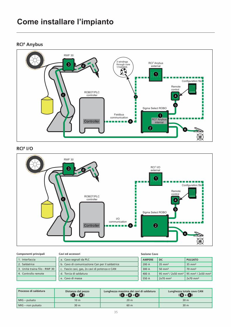
Processo di saldatura Distanza dal pezzo( + )
Lunghezza massima dei cavi di saldatura( + + )
Lunghezza totale cavo CAN( + )
MIG – pulsato 10 m 20 m 30 m
MIG – non pulsato 30 m 60 m 30 m
cc cbd d e
Sezione Cavo
AMPERE DC PULSATO
200 A 35 mm² 35 mm²
300 A 50 mm² 70 mm²
400 A 95 mm² / 2x50 mm² 95 mm² / 2x50 mm²
550 A 2x70 mm² 2x70 mm²
Componenti principali
1. Interfaccia
2. Saldatrice
3. Unità traina filo - RWF 30
4. Controllo remote
Cavi ed accessori
a. Cavo segnali da PLC
b. Cavo di comunicazione Can per il saldatrice
c. Fascio cavi, gas, 2x cavi di potenza e CAN
d. Torcia di saldatura
e. Cavo di massa

36
NOTA:Difetti suoi connettori causati da una errata installazione non sono coperti da garanzia!!!
Come installare l’impianto
Installazione del modulo Anybus
RCI4 Anybus interno RCI4 Anybus esterno
Collegamento I/O RCI4 esterno
SUB D 9 pol SUB D 25 pol
Collegamento CAN-BUS
1. Importante! Posizionare correttamente il modulo Anybus nel suo alloggiamento.
2. Premere leggermente il modulo in posizione e fissare il modulo Anybus utilizzando le viti.
1
22
1

36 37
Collegamenti ed uso
MIGA_CFG
DOCUMENTS
DeviceNet
EtherCAT
PROFIBUS
PROFINET
EtherNet-IP
Config.
Configurazione della RCI4 e Robot / PLCUtilizzare un file di configurazione per configurare RCI4. Scegli il tipo di file in base al tipo di assegnazione e RCI4 (I/O o Anybus)
a scheda SD inclusa nella fornitura, contiene vari file di configurazione e di installazione richiesti da alcuni robot e PLC.
Caricare le cartelle MIGA_CFG/DOCUMENTS su PC. Ogni cartella contiene i file EDS o GSD, manuali utente, guide rapide e varie documentazioni sui moduli di comunicazione Fieldbus.
Carica la cartella MIGA.CFG/ROBOT sul tuo PC per trovare informazioni su file di configurazione desiderato.
Sono disponibili i seguenti file di configurazione:10010208: SIGMA RCI Anybus10010210: Sigma RCI I/O, Program + process (DSUB25 only)10010211: Sigma RCI I/O, Program + sequence (DSUB25 only)10010212: Sigma RCI I/O, JOB (DSUB25 only)10010213: Sigma RCI I/O, JOB + sequence (DSUB 25+9)
38
Dati tecnici RCI4 I/O
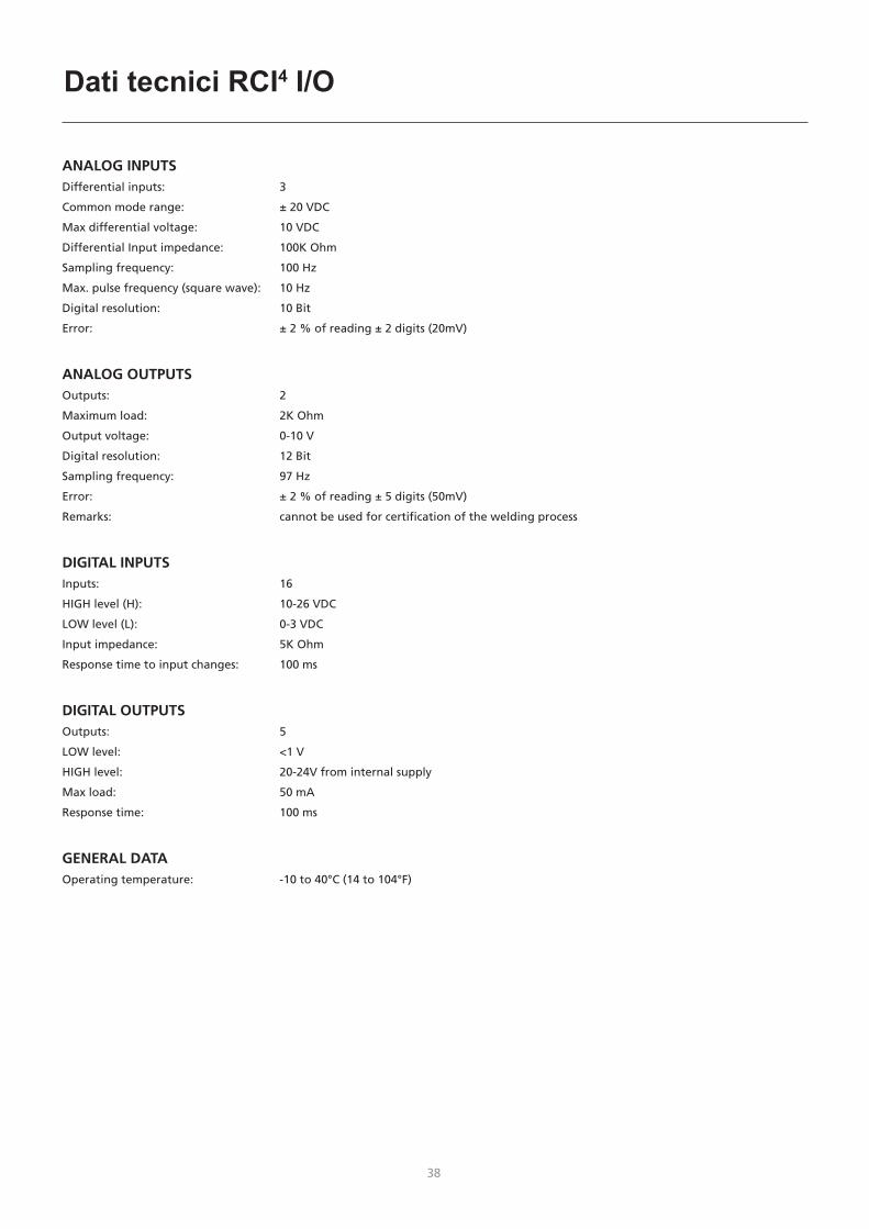
ANALOG INPUTSDifferential inputs: 3
Common mode range: ± 20 VDC
Max differential voltage: 10 VDC
Differential Input impedance: 100K Ohm
Sampling frequency: 100 Hz
Max. pulse frequency (square wave): 10 Hz
Digital resolution: 10 Bit
Error: ± 2 % of reading ± 2 digits (20mV)
ANALOG OUTPUTSOutputs: 2
Maximum load: 2K Ohm
Output voltage: 0-10 V
Digital resolution: 12 Bit
Sampling frequency: 97 Hz
Error: ± 2 % of reading ± 5 digits (50mV)
Remarks: cannot be used for certification of the welding process
DIGITAL INPUTSInputs: 16
HIGH level (H): 10-26 VDC
LOW level (L): 0-3 VDC
Input impedance: 5K Ohm
Response time to input changes: 100 ms
DIGITAL OUTPUTSOutputs: 5
LOW level: <1 V
HIGH level: 20-24V from internal supply
Max load: 50 mA
Response time: 100 ms
GENERAL DATAOperating temperature: -10 to 40°C (14 to 104°F)
38 39
Dati tecnici moduli Anybus
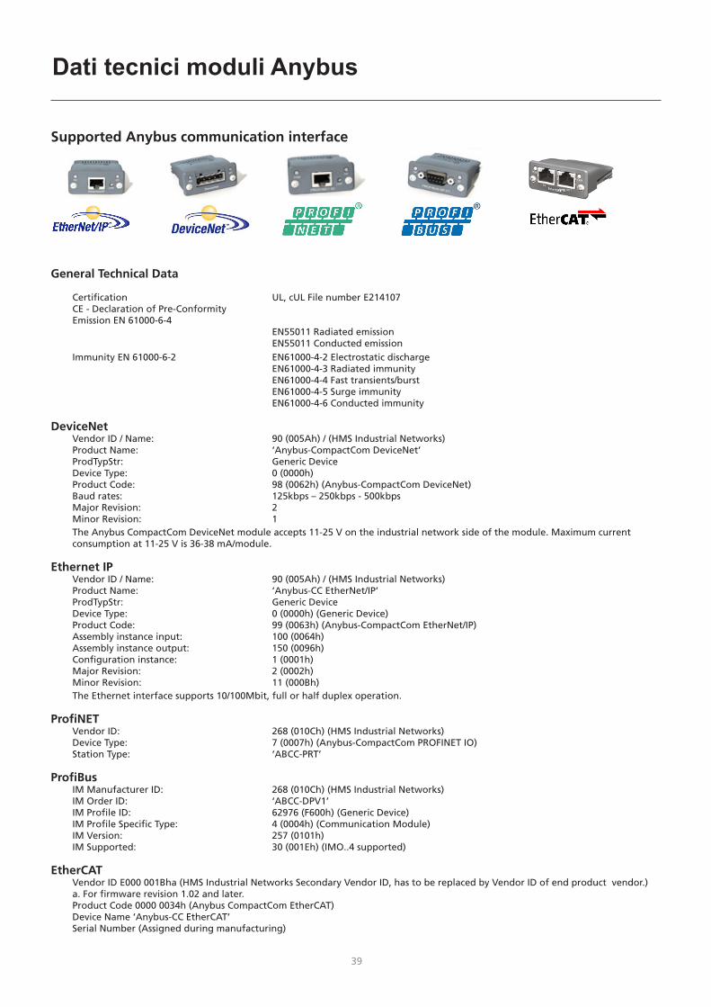
Supported Anybus communication interface
General Technical Data
Certification UL, cUL File number E214107 CE - Declaration of Pre-Conformity Emission EN 61000-6-4 EN55011 Radiated emission EN55011 Conducted emission Immunity EN 61000-6-2 EN61000-4-2 Electrostatic discharge EN61000-4-3 Radiated immunity EN61000-4-4 Fast transients/burst EN61000-4-5 Surge immunity EN61000-4-6 Conducted immunity
DeviceNet Vendor ID / Name: 90 (005Ah) / (HMS Industrial Networks) Product Name: ‘Anybus-CompactCom DeviceNet’ ProdTypStr: Generic Device Device Type: 0 (0000h) Product Code: 98 (0062h) (Anybus-CompactCom DeviceNet) Baud rates: 125kbps – 250kbps - 500kbps Major Revision: 2 Minor Revision: 1
The Anybus CompactCom DeviceNet module accepts 11-25 V on the industrial network side of the module. Maximum current consumption at 11-25 V is 36-38 mA/module.
Ethernet IP Vendor ID / Name: 90 (005Ah) / (HMS Industrial Networks) Product Name: ‘Anybus-CC EtherNet/IP’ ProdTypStr: Generic Device Device Type: 0 (0000h) (Generic Device) Product Code: 99 (0063h) (Anybus-CompactCom EtherNet/IP) Assembly instance input: 100 (0064h) Assembly instance output: 150 (0096h) Configuration instance: 1 (0001h) Major Revision: 2 (0002h) Minor Revision: 11 (000Bh)
The Ethernet interface supports 10/100Mbit, full or half duplex operation.
ProfiNET Vendor ID: 268 (010Ch) (HMS Industrial Networks) Device Type: 7 (0007h) (Anybus-CompactCom PROFINET IO) Station Type: ‘ABCC-PRT’
ProfiBus IM Manufacturer ID: 268 (010Ch) (HMS Industrial Networks) IM Order ID: ‘ABCC-DPV1’ IM Profile ID: 62976 (F600h) (Generic Device) IM Profile Specific Type: 4 (0004h) (Communication Module) IM Version: 257 (0101h) IM Supported: 30 (001Eh) (IMO..4 supported)
EtherCAT Vendor ID E000 001Bha (HMS Industrial Networks Secondary Vendor ID, has to be replaced by Vendor ID of end product vendor.) a. For firmware revision 1.02 and later. Product Code 0000 0034h (Anybus CompactCom EtherCAT) Device Name ‘Anybus-CC EtherCAT’ Serial Number (Assigned during manufacturing)

40
Led Anybus
EtherNet IP
# Articolo
1 Led di stato della rete
2 Led di stato del modulo
3 Collegamento/Activity
4 Interfaccia Ethernet
Led di stato della rete
Stato led Descrizione
Spento No alimentazione o indirizzo IP mancante
Verde In linea, una o più connessioni sono stabilite(CIP Class 1 or 3)
Verde, lampeggiante In linea, nessuna connessione stabilita
Rosso Indirizzo IP esistente, errore irreversibile
Rosso, lampeggiante Una o più connessioni sono state interrotte (CIP Class 1 or 3)
LED di stato del moduloNota: Una sequenza di test viene eseguita su questo LED durante l’avvio
Stato led Descrizione
Spento No alimentazione
Verde Controllato da uno scanner in stato RUN
Verde, lampeggiante Non configurato, o Scanner in stato di inattività
Rosso Errore maggiore (stato di ESECUZIONE, errore FATAL ecc.)
Rosso, lampeggiante Guasti ripristinabili
Collegamento/Attività LED
Stato led Descrizione
Spento Nessun collegamento, no attività
Verde Collegamento stabilito
Verde lampeggiante Attività
1 8
DeviceNet
# Articolo
1 Led di stato della rete
2 Led di stato del modulo
3 Connettore DeviceNet
4 Connettore femmina M12
5 Connettore maschio M12
Stato della rete
Stato Indicazione
Spento Non in linea/no alimentazione
Verde In linea, vengono stabilite una o più connessioni
Verde Lampeggiante (1 Hz) In linea, connessione non stabilita
Rosso Errore critico del collegamento
Rosso Lampeggiante (1 Hz) Una o più connessioni sono terminate
Rosso/Verde Alternato Test di autoverifica
Stato Modulo
Stato Indicazione
Spento No alimentazione
Verde Funzionamento in condizioni normali
Verde Lampeggiante (1 Hz) Configurazione mancante o incomplete, il dispositivo richieda la messa in servizio
Rosso Errore irreversibile
Rosso Lampeggiante (1 Hz) Guasti riparabili
Rosso/Verde Alternato Test di autoverifica
Connettore DeviceNetQuesto connettore fornisce la connessione DeviceNet
Pin Segnale Descrizione
1 V- Alimentazione bus -
2 CAN_L CAN low
3 SHIELD Schermatura cavo
4 CAN_H CAN high
5 V+ Alimentazione bus +

40 41
Led Anybus
PROFIBUS
# Articolo
1 Modalita di funzionamento
2 Stato
3 Connettore PROFIBUS
4 Connettore femmina M12
5 Connettore maschio M12
Modalità di funzionamento
Stato Indicazione
Spento Non in linea/ No alimetazione
Verde Scambio di dati
Verde Lampeggiante Libero
Rosso Lampeggiante (1 flash) Errore di parametrizzazione
Rosso Lampeggiante (2 flashes) Errore di configurazione PROFIBUS
Stato
Stato Indicazione Commenti
Spento Non inizializzato Stato Anybus = ‘SETUP’ o ‘NW_INIT’
Verde Inizializzato Il modulo Anybus ha las-ciato lo stato ‘NW_INIT’
Verde Lampeggiante Sono presenti eventi o eventi diagnostici inizializzati
È stato impostato il bit di diagnostica esteso
Rosso Errore di eccezione Stato Anybus = ‘EXCEPTION’
PROFINET IP
# Articolo
1 LED di stato della rete
2 LED di stato del modulo
3 LED Collegamento/Attività
4 Interfaccia Ethernet
LED di stato della rete
Nota: Una sequenza di test viene eseguita su questo LED durante l’avvio
Stato Led Descrizione Commenti
Spento Disconesso - Nessuna alimentazione- Nessuna connessione con
IO Controller
Verde Connesso (RUN)
- Collegamento con IO Controller stabilito
- Controller IO in stato RUN
Verde, lampeggiante
Connesso (STOP)
- Collegamento con IO Controller stabilito
- Controller IO in stato STOP
LED di stato del moduloNota: Una sequenza di test viene eseguita su questoLED durante l’avvio
Stato Led Descrizione Commenti
Spento Non inizializzato
Nessuna alimentazione o modulo nello stato ‘SETUP’ o ‘NW_INIT’
Verde Operazione normale
Il modulo è stato spostato dallo stato ‘NW_INIT’
Verde, 1 flash
Evento diagnostico
Evento diagnostico presente
Verde, 2 flashes
Blink Utilizzato dalla strumetnazione per indentificare il nodo della rete
Rosso Errore “Exception”
Modulo in stato ‘EXCEPTION’
Rosso, 1 flash
Errore di configurazione
Identificazione prevista differisce dall’identificazione reale
Rosso, 2 flashes
Errore indirizzo IP
Indirizzo IP non impostato
Rosso, 3 flashes
Errore nome stazione
Nome stazione non impostato
Rosso, 4 flashes
Errore interno Il modulo ha riscontrato un grave errore interno
LED COLLEGAMENTO/Attività
Stato Led Descrizione Commenti
Spento Nessun Collegamento
Nessun collegamento presente
Verde Collegato Collegamento Ethernet stabilito, nessuna comunicazione presente
Verde, lampeggiante
Attività Collegamento Ethernet stabilito, comunicazione presente
Interfaccia EthernetL’interfaccia Ethernet funziona a 100 Mbit, full duplex, con la negoziazione automatica attivata come impostazione predefinita.
1 8

42
Led Anybus
EtherCATConnettore EtherCat
# Articolo
1 RUN led
2 Led di errore
3 EtherCAT (porta 1)
4 EtherCAT (porta 2)
5 Collegamento/Attività (porta 1)
6 Collegamento/Attività (porta 2)
RUN LEDQuesto LED riflette lo stato della comunicazione CoE (CANopen over EtherCAT)
Stato Led Indicazione Descrizione
Spento INIT Dispositivo CoE in Stato “INIT” (o nessuna alimentazione)
Verde OPERATIONAL Dispositivo CoE in stato‘OPERATIONAL’
Verde, lampeggiante
PRE-OPERATIONAL
Dispositivo CoE in stato‘PRE-OPERATIONAL’
Verde, singolo flash
SAFE-OPERATIONAL
Dispositivo CoE in stato‘SAFE-OPERATIONAL’
Rossoa Evento fatale -
a. Se RUN e ERR diventano rossi, ciò indica un evento fatale, costringendo l’interfaccia bus ad uno stato fisicamente passivo. Contattare il supporto tecnico HMS
Led erroriQuesto LED indica errori di comunicazione EtherCAT ecc.
Stato Led Indicazione Descrizione
Spento Nessuno errore Nessun errore (o nessuna alimentazione)
Rosso, Lampeggiante
Configurazione non valida
La modifica di stato ricevuta dal master non è possibile a causa di impostazioni di registro o di oggetti non validi
Rosso, doppio flash
Timeout applicazione watchdog
Gestore dellla sincronizzazione watchdog in timeout
Rossoa Errore del controller di applicazione
Modulo Anybus in EXCEPTION
a. Se RUN e ERR diventano rossi, ciò indica un evento fatale, costringendo l’interfaccia bus ad uno stato fisicamente passivo. Contattare il supporto tecnico HMS.
Collegamento/Attività Questi LED indicano lo stato e l’attività del collegamento EtherCAT
Stato Led Indicazione Descrizione
Spento Collegamemto assente
Collegamento non rilevato (nessuna alimentazione)
Verde Collegamento rilevato, nessuna comunicazione
Collegamento rilevato, nessun traffico rilevato
Verde, lampeggiante
Collegamento rilevato, in comunicazione
Collegamento e traffico rilevati
6
42 43
Hoe de installatie aan te sluiten?
Controller
d
ROBOT/PLCcontroller
RWF 30
Sigma Select ROBO
Remotecontrol
Fieldbuscommunication
b
4
e
c
a
2
1
3
Configuration file
1
3 windingsthrough core17440005
RCI4Anybus
external
RCI4Anybus
internal
RCI4 Anybus
Controller
d
ROBOT/PLCcontroller
RWF 30
Sigma Select ROBO
Remotecontrol
I/Ocommunication
b
4
e
c
a 2
3RCI I/Oexternal
4
Configuration file
1
RCI4 I/O
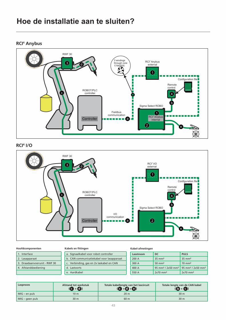
Lasproces Afstand tot werkstuk( + )
Totale kabellengte van het lascircuit( + + )
Totale lengte van de CAN kabel( + )
MIG – en puls 10 m 20 m 30 m
MIG – geen puls 30 m 60 m 30 m
cc cbd d e
Kabel-afmetingen
Lasstroom DC PULS
200 A 35 mm² 35 mm²
300 A 50 mm² 70 mm²
400 A 95 mm² / 2x50 mm² 95 mm² / 2x50 mm²
550 A 2x70 mm² 2x70 mm²
Hoofdcomponenten
1. Interface
2. Lasapparaat
3. Draadaanvoerunit - RWF 30
4. Afstandsbediening
Kabels en fittingen
a. Signaalkabel voor robot controller
b. CAN communicatiekabel voor lasapparaat
c. Verbinding, gas en 2x laskabel en CAN
d. Lastoorts
e. Aardkabel

44
Opmerking:Op defecte connectors kan geen garantie worden geclaimd.
Hoe de installatie aan te sluiten?
Installatie van de Anybus module
RCI4 Anybus intern RCI4 Anybus extern
Verbinden van RCI4 I/O extern
SUB D 9 pol SUB D 25 pol
CAN verbinding
1. Belangrijk! Zodra de Anybus module is geïnstalleerd, steek de plug recht in de uitsparing.
2. Druk de plug voorzichtig in positie en zet de Anybus module vast; gebruik hiervoor de schroeven.
1
22
1

44 45
Aansluiting en bediening
MIGA_CFG
DOCUMENTS
DeviceNet
EtherCAT
PROFIBUS
PROFINET
EtherNet-IP
Config.
Configuratie van RCI4 en Robot / PLCGebruik een configuratiebestand om RCI4 te configureren. Kies bestandstype volgens toewijzing en type RCI4 (I / O of Anybus).
De SD-kaart bevat verschillende configuratie- en setup bestanden die door sommige robots en PLC’s zijn vereist.
Installeer de MIGA_CFG/DOCUMENTS mappen op uw PC. Elke map bevat EDS of GSD-bestanden, gebruikershandleidingen, verkorte handleidingen en diverse Fieldbus module documentatie voor communicatie-apparatuur.
Laad de MIGA.CFG/ROBOT-map op uw pc om informatie te vinden over het gewenste configuratiebestand.
De volgende configuratiebestanden zijn beschikbaar:10010208: SIGMA RCI Anybus10010210: Sigma RCI I/O, Program + process (DSUB25 only)10010211: Sigma RCI I/O, Program + sequence (DSUB25 only)10010212: Sigma RCI I/O, JOB (DSUB25 only)10010213: Sigma RCI I/O, JOB + sequence (DSUB 25+9)

46
Technische gegevens RCI4 I/O
ANALOG INPUTSDifferential inputs: 3
Common mode range: ± 20 VDC
Max differential voltage: 10 VDC
Differential Input impedance: 100K Ohm
Sampling frequency: 100 Hz
Max. pulse frequency (square wave): 10 Hz
Digital resolution: 10 Bit
Error: ± 2 % of reading ± 2 digits (20mV)
ANALOG OUTPUTSOutputs: 2
Maximum load: 2K Ohm
Output voltage: 0-10 V
Digital resolution: 12 Bit
Sampling frequency: 97 Hz
Error: ± 2 % of reading ± 5 digits (50mV)
Remarks: cannot be used for certification of the welding process
DIGITAL INPUTSInputs: 16
HIGH level (H): 10-26 VDC
LOW level (L): 0-3 VDC
Input impedance: 5K Ohm
Response time to input changes: 100 ms
DIGITAL OUTPUTSOutputs: 5
LOW level: <1 V
HIGH level: 20-24V from internal supply
Max load: 50 mA
Response time: 100 ms
GENERAL DATAOperating temperature: -10 to 40°C (14 to 104°F)

46 47
Supported Anybus communication interface
General Technical Data
Certification UL, cUL File number E214107 CE - Declaration of Pre-Conformity Emission EN 61000-6-4 EN55011 Radiated emission EN55011 Conducted emission Immunity EN 61000-6-2 EN61000-4-2 Electrostatic discharge EN61000-4-3 Radiated immunity EN61000-4-4 Fast transients/burst EN61000-4-5 Surge immunity EN61000-4-6 Conducted immunity
DeviceNet Vendor ID / Name: 90 (005Ah) / (HMS Industrial Networks) Product Name: ‘Anybus-CompactCom DeviceNet’ ProdTypStr: Generic Device Device Type: 0 (0000h) Product Code: 98 (0062h) (Anybus-CompactCom DeviceNet) Baud rates: 125kbps – 250kbps - 500kbps Major Revision: 2 Minor Revision: 1
The Anybus CompactCom DeviceNet module accepts 11-25 V on the industrial network side of the module. Maximum current consumption at 11-25 V is 36-38 mA/module.
Ethernet IP Vendor ID / Name: 90 (005Ah) / (HMS Industrial Networks) Product Name: ‘Anybus-CC EtherNet/IP’ ProdTypStr: Generic Device Device Type: 0 (0000h) (Generic Device) Product Code: 99 (0063h) (Anybus-CompactCom EtherNet/IP) Assembly instance input: 100 (0064h) Assembly instance output: 150 (0096h) Configuration instance: 1 (0001h) Major Revision: 2 (0002h) Minor Revision: 11 (000Bh)
The Ethernet interface supports 10/100Mbit, full or half duplex operation.
ProfiNET Vendor ID: 268 (010Ch) (HMS Industrial Networks) Device Type: 7 (0007h) (Anybus-CompactCom PROFINET IO) Station Type: ‘ABCC-PRT’
ProfiBus IM Manufacturer ID: 268 (010Ch) (HMS Industrial Networks) IM Order ID: ‘ABCC-DPV1’ IM Profile ID: 62976 (F600h) (Generic Device) IM Profile Specific Type: 4 (0004h) (Communication Module) IM Version: 257 (0101h) IM Supported: 30 (001Eh) (IMO..4 supported)
EtherCAT Vendor ID E000 001Bha (HMS Industrial Networks Secondary Vendor ID, has to be replaced by Vendor ID of end product vendor.) a. For firmware revision 1.02 and later. Product Code 0000 0034h (Anybus CompactCom EtherCAT) Device Name ‘Anybus-CC EtherCAT’ Serial Number (Assigned during manufacturing)
Technische gegevens Anybus-modules

48
Anybus-indicatoren
EtherNet IP
# Item
1 Netwerk status LED
2 Module status LED
3 Verbinding/Activiteit
4 Ethernet interface
Netwerk Status LED
LED Status Omschrijving
Uit Geen spanning of geen IP adres
Groen On-line, een of meerdere verbindingen zijn tot stand gekomen (CIP Klasse 1 of 3)
Groen, knipperend On-line, geen verbindingen zijn tot stand gekomen
Rood Dubbele IP adressen, FATALE fout
Rood, knipperend Een of meerdere verbindings-onderbrekingen (CIP Klasse 1 of 3)
Module Status LEDOpmerking: Een test wordt uitgevoerd op deze LED tijdens opstarten
LED Status Omschrijving
Uit Geen spanning
Groen Gecontroleerd door een Scanner in uitvoerende status
Groen, knipperend Niet geconfigureerd, of Scanner in lege status
Rood Belangrijke storing (UITZONDERING-status, FATALE fout etc.)
Rood, knipperend Herstelbare fout(en)
VERBINDING/Activiteit LED
LED Status Omschrijving
Uit Geen verbinding, geen activiteiten
Groen Verbinding tot stand gekomen
Groen knipperend Activiteit
1 8
DeviceNet
# Item
1 Network status LED
2 Module status LED
3 DeviceNet connector
4 M12 connector vrouw
5 M12 connector man
Network Status
Status Indicatie
Uit Niet online/Geen spanning
Groen On-line , een of meer verbindingen zijn tot stand gekomen
Knippert Groen (1Hz) On-line, geen verbindingen zijn tot stand gekomen
Rood Kritische verbindingsfout
Knippert Rood (1Hz) Een of meerdere verbindings- onderbrekingen
Afwisselend Rood/Groen
Zelf test
Module Status
Status Indicatie
Uit Geen spanning
Groen Werking in normale conditie
Knippert Groen (1Hz) Ontbrekende of onvolledige configuratie, apparaat moet in bedrijf worden gesteld.
Rood Onherstelbare fout(en)
Knippert Rood (1Hz) Herstelbare fout(en)
Afwisselend Rood/Groen
Zelf test
DeviceNet ConnectorDeze connector biedt DeviceNet verbindingen
Pin Signal Omschrijving
1 V- Negative bus supply voltage
2 CAN_L CAN low bus line
3 SHIELD Cable shield
4 CAN_H CAN high bus line
5 V+ Positive bus supply voltage

48 49
Anybus-indicatoren
PROFIBUS
# Item
1 Operatie Modus
2 Status
3 PROFIBUS Connector
4 M12 Connector Vrouw
5 M12 Connector Man
Operatie Modus
Status Indicatie
Uit Niet online/Geen spanning
Groen Data vervangen
Groen Knipperend Leeg
Rood knipperend (1 flits) Parametrisatie fout
Rood Knipperend (2 flitsen) PROFIBUS Configuratie fout
Status
Status Indicatie Commentaar
Uit Niet geinitialiseerd Anybus status= ‘SETUP¨’ of ‘NW_INIT’
Groen Geinitialiseerd Anybus module heeft de ‘NW_INIT’ status verlaten
Groen Knipperend
Geinitialiseerde diagnostische gebeurtenis(sen) aanwezig
Uitgebreide diagnostische bit is ingesteld
Rood Uitzonderingsfout Anybus status = ‘UITGEZONDERD’
PROFINET IP
# Item
1 Netwerk status LED
2 Module status LED
3 Verbinding/Activiteit LED
4 Ethernet Interface
Netwerk LED Status
Opmerking: Een test wordt uitgevoerd op deze LED tijdens opstarten
LED Status Omschrijving Commentaar
Uit Geen verbinding
- Geen spanning- Geen verbinding met IO Controller
Groen Verbinding (UITVOEREN
- Verbinding met IO Controller tot stand gekomen
- IO Controller in uitvoerende status
Groen Knipperend
Verbinding (STOP)
- Verbinding met IO Controller tot stand gekomen
- IO controller in STOP status
Module LED StatusOpmerking: Een test wordt uitgevoerd op deze LED tijdens opstarten
LED Status Omschrijving Commentaar
Uit Niet geinitialiseerd
Geen spanning - of - Module in ‘SETUP’ of ‘NW_INIT’ status
Groen NormaalOperatie
Module is verschoven van de ‘NW_INIT’ status
Groen1 flits
Diagnostisch gebeuren
Diagnostische gebeurtenis aanwezig
Groen2 flitsen
Knippert Gebruik engineersgereedschap om het knooppunt op het netwerk te identificeren.
Rood Uitzonderings-fout
Module in status ‘UITGEZONDERD’
Rood 1 flits Configuratie-fout
Verwachte identificatie verschilt van echte identificatie
Rood 2 flitsen
IP adres fout IP adres niet ingesteld
Rood 3 flitsen
Stationsnaam fout
Stationsnaam niet ingesteld
Rood4 flitsen
Interne fout Module has encountered a major internal error
VERBINDING/Activiteit LED
LED Status Omschrijving Commentaar
Uit Geen verbinding
Geen verbinding, geen communicatie aanwezig
Groen Verbinding Ethernet verbinding tot stand gekomen, geen communicatie aanwezig
Groen, knippert
Activiteit Ethernet verbinding tot stand gekomen, communicatie aanwezig
Ethernet InterfaceDe Ethernet interface werkt op 100 Mbit, full-duplex, met overdracht modus als standaard ingeschakeld.
1 8

50
Anybus-indicatoren
EtherCATEtherCAT Connector
# Item
1 LED UITVOEREN
2 LED FOUT
3 EtherCAT (Poort 1)
4 EtherCAT (Poort 2)
5 Verbinding/Activiteit (Poort 1)
6 Verbinding/Activiteit (Poort 2)
RUN LEDDeze LED reflecteert de status van de CoE (CANopen over EtherCAT) communicatie
LED Status Indicatie Omschrijving
Uit INIT CoE apparaat in ‘INIT’-staat (of geen spanning)
Groen OPERATIONEEL CoE apparaat in ‘OPERATIONELE’-status
Groen knippert
PRE-OPERATIONEEL CoE apparaat in ‘PRE-OPERATIONELE’-status
Groen enkel flits
VEILIG-OPERATIONEEL
CoE apparaat in ‘VEILIG-OPERATIONELE’-status
Rooda (Fataal probleem) -
a. Als de RUN en ERR rood oplichten, toont dat aan dat er een fataal probleem is opgetreden. Het dwingt de bus interface naar een fysieke passieve toestand. Neem contact op met HMS technische ondersteuning.
ERR LEDDeze LED toont EtherCAT communicatie problemen etc.
LED Status Indicatie Omschrijving
Uit Geen storing Geen storing (of geen spanning)
Roodknippert
Ongeldigeconfiguratie
Het ontvangen van status verandering van master is niet mogelijk vanwege ongeldige register- of object instellingen.
Rood dubbel flits
Applicatie waakhond time-out
Sync manager waakhond time-out
Rooda Fout bij applicatie controller
Anybus module in UITZONDERING
a. Als RUN en ERR rood oplichten, toont dat aan dat er een fataal probleem is opgetreden. Het dwingt de bus interface naar een fysieke passieve toestand. Neem contact op met HMS technische ondersteuning.
VERBINDING/ActiviteitDeze LED’s tonen aan de EtherCAT verbinding status en activiteit
LED Status Indicatie Omschrijving
Uit Geen verbinding Verbinding niet gedetecteerd (of geen spanning)
Groen Verbinding gedetecteerd geen activiteit
Verbinding gedetecteerd, geen verkeer gedetecteerd
Groen knippert
Verbinding en activiteit gedetecteerd
Verbinding en verkeer gedetecteerd
6

50 51
Ovládací
d
ROBOT/PLCovládací jednotka
RWF 30
Sigma Select ROBO
Dálkovýovládací
panel
Fieldbuskomunikace
b
4
e
c
a
2
1
3
Konfigura nísoubor
č
1
3 x vinutíp es jádro17440005ř RCI
4Anybus
externí
RCI4Anybus
interní/vestav nýě
RCI4 Anybus
d
RWF 30
Sigma Select ROBO
I/Okomunikace
b
4
e
c
a 2
3 RCI I/Oexterní
4
1
ROBOT/PLCovládací jednotka
Ovládací
Dálkovýovládací
panel
Konfigura nísoubor
č
RCI4 I/O
Svařovací proces Vzdálenost od svařence( + )
Celková délka kabelů ve svařovacím obvodu( + + )
Celková délka CAN kabelu( + )
MIG – a impulz 10 m 20 m 30 m
MIG – neimpulzní 30 m 60 m 30 m
cc cbd d e
Průřez kabelů
Svařovací proud DC Impulz
200 A 35 mm² 35 mm²
300 A 50 mm² 70 mm²
400 A 95 mm² / 2x50 mm² 95 mm² / 2x50 mm²
550 A 2x70 mm² 2x70 mm²
Hlavní komponenty
1. Interface
2. Svařovací zdroj
3. Robotický podavač - RWF 30
4. Dálková regulace
Kabely a jejich příslušenství
a. Komunikační kabel pro řídící jednotku robota
b. CAN komunikační kabel pro Remote2
c. Mezikabel (obsahuje plyn, 2x svařovací kabel a CAN)
d. Svařovací hořák
e. Zemnící kabel
Doporučený způsob zapojení

52
Doporučený způsob zapojení
Instalace Anybus modulu
RCI4 Anybus interní/vestavěný RCI4 Anybus externí
1
22
1
RCI4 I/O externí - popis konektorů
SUB D 9 pol SUB D 25 pol
Konektor CAN
1. Důležité ! Anybus modul musí být vložen rovně a přímo do otvoru.
2. Mírně zatlačte modul do správné polohy a utáhněte Anybus modul pomocí šroubů.
POZNÁMKA:Na poškozené konektory během instalace se nevztahuje záruka!!!

52 53
Připojení a provoz
MIGA_CFG
DOCUMENTS
DeviceNet
EtherCAT
PROFIBUS
PROFINET
EtherNet-IP
Config.
Konfigurace interface RCI4 a ROBOT/PLC Použijte konfigurační soubor pro konfiguraci RCI4. Vyberte typ souboru podle přiřazení a typu RCI4 (I / O nebo Anybus).
Karta SD obsažená v dodávce obsahuje různé konfigurační soubory a instalační soubory požadované některými roboty a PLC.
SD karta obsahuje v adresáři MIGA_CFG/ DOCUMENTS specifické EDS/GSD soubory, návody k obsluze, rychlé průvodce a dokumentaci k různým typům Anybus modulů.
Vložte kartu do Vašeho PC, v adresáři MIGA.CFG/ROBOT vyhledejte informace o požadovaném konfiguračním souboru.
K dispozici jsou následující konfigurační soubory:10010208: SIGMA RCI Anybus10010210: Sigma RCI I/O, Program + process (DSUB25 only)10010211: Sigma RCI I/O, Program + sequence (DSUB25 only)10010212: Sigma RCI I/O, JOB (DSUB25 only)10010213: Sigma RCI I/O, JOB + sequence (DSUB 25+9)

54
Technická data RCI4 I/O
ANALOG INPUTSDifferential inputs: 3
Common mode range: ± 20 VDC
Max differential voltage: 10 VDC
Differential Input impedance: 100K Ohm
Sampling frequency: 100 Hz
Max. pulse frequency (square wave): 10 Hz
Digital resolution: 10 Bit
Error: ± 2 % of reading ± 2 digits (20mV)
ANALOG OUTPUTSOutputs: 2
Maximum load: 2K Ohm
Output voltage: 0-10 V
Digital resolution: 12 Bit
Sampling frequency: 97 Hz
Error: ± 2 % of reading ± 5 digits (50mV)
Remarks: cannot be used for certification of the welding process
DIGITAL INPUTSInputs: 16
HIGH level (H): 10-26 VDC
LOW level (L): 0-3 VDC
Input impedance: 5K Ohm
Response time to input changes: 100 ms
DIGITAL OUTPUTSOutputs: 5
LOW level: <1 V
HIGH level: 20-24V from internal supply
Max load: 50 mA
Response time: 100 ms
GENERAL DATAOperating temperature: -10 to 40°C (14 to 104°F)

54 55
Supported Anybus communication interface
General Technical Data
Certification UL, cUL File number E214107 CE - Declaration of Pre-Conformity Emission EN 61000-6-4 EN55011 Radiated emission EN55011 Conducted emission Immunity EN 61000-6-2 EN61000-4-2 Electrostatic discharge EN61000-4-3 Radiated immunity EN61000-4-4 Fast transients/burst EN61000-4-5 Surge immunity EN61000-4-6 Conducted immunity
DeviceNet Vendor ID / Name: 90 (005Ah) / (HMS Industrial Networks) Product Name: ‘Anybus-CompactCom DeviceNet’ ProdTypStr: Generic Device Device Type: 0 (0000h) Product Code: 98 (0062h) (Anybus-CompactCom DeviceNet) Baud rates: 125kbps – 250kbps - 500kbps Major Revision: 2 Minor Revision: 1
The Anybus CompactCom DeviceNet module accepts 11-25 V on the industrial network side of the module. Maximum current consumption at 11-25 V is 36-38 mA/module.
Ethernet IP Vendor ID / Name: 90 (005Ah) / (HMS Industrial Networks) Product Name: ‘Anybus-CC EtherNet/IP’ ProdTypStr: Generic Device Device Type: 0 (0000h) (Generic Device) Product Code: 99 (0063h) (Anybus-CompactCom EtherNet/IP) Assembly instance input: 100 (0064h) Assembly instance output: 150 (0096h) Configuration instance: 1 (0001h) Major Revision: 2 (0002h) Minor Revision: 11 (000Bh)
The Ethernet interface supports 10/100Mbit, full or half duplex operation.
ProfiNET Vendor ID: 268 (010Ch) (HMS Industrial Networks) Device Type: 7 (0007h) (Anybus-CompactCom PROFINET IO) Station Type: ‘ABCC-PRT’
ProfiBus IM Manufacturer ID: 268 (010Ch) (HMS Industrial Networks) IM Order ID: ‘ABCC-DPV1’ IM Profile ID: 62976 (F600h) (Generic Device) IM Profile Specific Type: 4 (0004h) (Communication Module) IM Version: 257 (0101h) IM Supported: 30 (001Eh) (IMO..4 supported)
EtherCAT Vendor ID E000 001Bha (HMS Industrial Networks Secondary Vendor ID, has to be replaced by Vendor ID of end product vendor.) a. For firmware revision 1.02 and later. Product Code 0000 0034h (Anybus CompactCom EtherCAT) Device Name ‘Anybus-CC EtherCAT’ Serial Number (Assigned during manufacturing)
Technická data echnická data Anybus modulu

56
Anybus indikační stavové diody
EtherNet IP
# Pozice
1 Indikační síťová dioda
2 Indikační dioda modulu
3 Aktivita spojení
4 Ethernet Interface
Status sítě
LED status Popis
Vypnuto Chybí napájení nebo není definována IP adresa
Zelená On-line, jedno nebo více spojení je navázáno (CIP třída 1 nebo 3)
Blikající zelená On-line, není navázána komunikace
Červená Duplicita IP adresy, fatální chyba
Blikající červená Vypršel čas pro navázání komunikace (CIP třída 1 nebo 3)
Status modulu Poznámka : Během spuštění se na této LED provede testovací
sekvence
LED status Popis
Vypnuto Chybí napájení
Zelená Kontrolováno skenerem v režimu provozu
Blikající zelená Není konfigurováno nebo skener je v nečinném provozu
Červená Hlavní chyba ( stav výjimky, fatální chyba etc.)
Blikající červená Obnovitelná chyba (y)
Spojení /aktivita LED
LED status Popis
Vypnuto Není spojení/aktivita
Zelená Spojení navázáno
Blikající zelená Aktivita
1 8
DeviceNet
# Pozice
1 Indikační síťová dioda
2 Indikační dioda modulu
3 DeviceNet konektor
4 M12 Zástrčka
5 M 12 zásuvka
Status sítě
Stav Indikace
Vypnuto Není online / napájení
Zelená On-line, jedno nebo více spojení je navázáno
Blikající zelená (1 Hz) On-line, není navázána komunikace
Červená Kritická chyba spojení
Blikající červená (1 Hz) Vypršel čas pro navázání komunikace
Střídání červená/zelená Interní test
Status modulu
Stav Indikace
Vypnuto Chybí napájení
Zelená Provoz v normálním stavu
Blikající zelená (1 Hz) Chybějící nebo neúplná konfigurace, zařízení potřebuje uvedení do provozu
Červená Neobnovitelná chyba (y)
Blikající červená (1 Hz) Obnovitelná chyba (y)
Střídání červená/zelená Interní test
DeviceNet konektorKonektor zabezpečuje DeviceNet konektivitu
Pin Signal Popis
1 V- Záporné napájecí napětí sběrnice
2 CAN_L Kanál s nízkým CAN připojením
3 SHIELD Stínění
4 CAN_H Kanál s vysokým CAN připojením
5 V+ Kladné napájecí napětí sběrnice
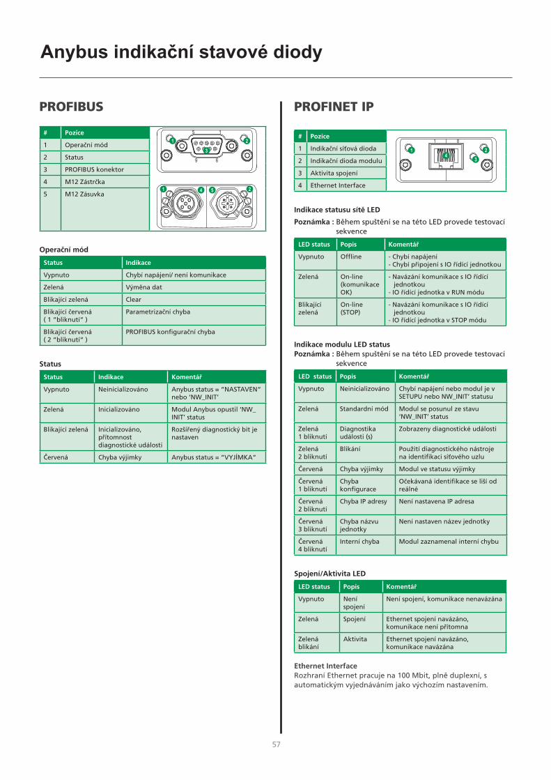
56 57
Anybus indikační stavové diody
PROFIBUS
# Pozice
1 Operační mód
2 Status
3 PROFIBUS konektor
4 M12 Zástrčka
5 M12 Zásuvka
Operační mód
Status Indikace
Vypnuto Chybí napájení/ není komunikace
Zelená Výměna dat
Blikající zelená Clear
Blikající červená ( 1 “bliknutí“ )
Parametrizační chyba
Blikající červená ( 2 “bliknutí“ )
PROFIBUS konfigurační chyba
Status
Status Indikace Komentář
Vypnuto Neinicializováno Anybus status = “NASTAVEN“ nebo ‘NW_INIT’
Zelená Inicializováno Modul Anybus opustil ‘NW_INIT’ status
Blikající zelená Inicializováno, přítomnost diagnostické události
Rozšířený diagnostický bit je nastaven
Červená Chyba výjimky Anybus status = “VYJÍMKA“
PROFINET IP
# Pozice
1 Indikační síťová dioda
2 Indikační dioda modulu
3 Aktivita spojení
4 Ethernet Interface
Indikace statusu sítě LED
Poznámka : Během spuštění se na této LED provede testovací sekvence
LED status Popis Komentář
Vypnuto Offline - Chybí napájení - Chybí připojení s IO řídící jednotkou
Zelená On-line (komunikace OK)
- Navázání komunikace s IO řídící jednotkou
- IO řídící jednotka v RUN módu
Blikající zelená
On-line (STOP)
- Navázání komunikace s IO řídící jednotkou
- IO řídící jednotka v STOP módu
Indikace modulu LED statusPoznámka : Během spuštění se na této LED provede testovací
sekvence
LED status Popis Komentář
Vypnuto Neinicializováno Chybí napájení nebo modul je v SETUPU nebo NW_INIT’ statusu
Zelená Standardní mód Modul se posunul ze stavu ‘NW_INIT’ status
Zelená 1 bliknutí
Diagnostika události (s)
Zobrazeny diagnostické události
Zelená 2 bliknutí
Blikání Použití diagnostického nástroje na identifikaci síťového uzlu
Červená Chyba výjimky Modul ve statusu výjimky
Červená 1 bliknutí
Chyba konfigurace
Očekávaná identifikace se liší od reálné
Červená 2 bliknutí
Chyba IP adresy Není nastavena IP adresa
Červená 3 bliknutí
Chyba názvu jednotky
Není nastaven název jednotky
Červená 4 bliknutí
Interní chyba Modul zaznamenal interní chybu
Spojení/Aktivita LED
LED status Popis Komentář
Vypnuto Není spojení
Není spojení, komunikace nenavázána
Zelená Spojení Ethernet spojení navázáno, komunikace není přítomna
Zelená blikání
Aktivita Ethernet spojení navázáno, komunikace navázána
Ethernet InterfaceRozhraní Ethernet pracuje na 100 Mbit, plně duplexní, s automatickým vyjednáváním jako výchozím nastavením.
1 8

58
Anybus indikační stavové diody
EtherCATEtherCAT konektor
# Pozice
1 Indikace RUN
2 Indikace chyby
3 EtherCAT (port 1)
4 EtherCAT (port 2)
5 Spojení/aktivita (port 1)
6 Spojení/aktivita (port 2)
Indikace RUN LED Tato indikační LED odráží stav komunikace CoE ((CANopen přes EtherCAT)
LED status Indikace Popis
Vypnutí INIT CoE zařízení je ve statusu “INIT“ (nebo chybí napájení )
Zelená Provoz CoE zařízení je ve statusu “PROVOZ“
Zelená blikání
Předoperační provoz
CoE zařízení je ve statusu “PŘEDOPERAČNÍ PROVOZ“
Zelená jednoduché blikání
Bezpečný provoz CoE zařízení je ve statusu “BEZPEČNÝ PROVOZ“
Červenáa (Fatální událost) -
a. Pokud se RUN a ERR zčervená, znamená to fatální událost, která nutí rozhraní sběrnice do fyzicky pasivního stavu.
Kontaktujte technickou podporu společnosti HMS
ERR LED indikaceTato LED indikuje chyby komunikace EtherCAT atd.
LED status Indikace Popis
Vypnutí Bez chyby Bez chyby ( nebo bez napájení)
Červená blikání
Neplatná konfigurace
Přijatá změna stavu od “mastra“ není možní z důvodu neplatného nastavení registru nebo objektu
Červená dvojité blikání
Vypršel časový limit
Vypršení časového limitu Sync manageru
Červenáa Chyba správce komunikace
Anybus modul ve výjimce
a. Pokud se RUN a ERR zčervená, znamená to fatální událost, která nutí rozhraní sběrnice do fyzicky pasivního stavu.
Kontaktujte technickou podporu společnosti HMS
Spojení/Aktivita LEDTyto LED diody indikují stav a aktivitu komunikace EtherCat
LED status Indikace Popis
Vypnuto Není spojení Není spojení (nebo chybí napájení)
Zelená Spojení, bez aktivity
Spojení, nebyl zjištěn žádný provoz
Zelená blikání
Spojení, aktivita detekována
Spojení provoz zjištěn
6

58 59
Jak wykonać podłączenie
Controller
d
ROBOT/PLCcontroller
RWF 30
Sigma Select ROBO
Remotecontrol
Fieldbuscommunication
b
4
e
c
a
2
1
3
Configuration file
1
3 windingsthrough core17440005
RCI4Anybus
external
RCI4Anybus
internal
Magistrala RCI4 Anybus
Controller
d
ROBOT/PLCcontroller
RWF 30
Sigma Select ROBO
Remotecontrol
I/Ocommunication
b
4
e
c
a 2
3RCI I/Oexternal
4
Configuration file
1
I/O RCI4 /wej/wyj/
Proces spawania Odległość od spawanego przedmiotu( + )
Łączna długość przewodu w obwodzie spawalniczym( + + )
Całkowita długość przewodu CAN( + )
MIG – i pulsacja 10 m 20 m 30 m
MIG – bez pulsacji 30 m 60 m 30 m
cc cbd d e
Przekrój przewodu
Prąd spawania DC /prąd stały PRĄD PULSACYJNY
200 A 35 mm² 35 mm²
300 A 50 mm² 70 mm²
400 A 95 mm² / 2x50 mm² 95 mm² / 2x50 mm²
550 A 2x70 mm² 2x70 mm²
Główne komponenty
1. Interfejs
2. Spawarka
3. Zespół podawania drutu - RWF 30
4. Zdalne sterowanie
Kable i przyłącza
a. Kabel sterowniczy kontrolera robota
b. Kabel komunikacyjny CAN spawarki
c. Podłączenie - gaz i 2x kable spawalnicze oraz CAN
d. Uchwyty spawalnicze
e. Kabel powrotny

60
Jak wykonać podłączenie
Montaż modułu magistrali Anybus
Moduł wewnętrzny RCI4 Anybus Moduł zewnętrzny RCI4 Anybus
1
22
1
Zewnętrzne podłączenie I/O RCI4
SUB D 9 pol SUB D 25 pol
Podłączenie magistrali CAN
1. Ważne! Kiedy moduł Anybus jest juz zamontowany wprowadź wtyczkę prosto do gniazda.
2. Naciśnij lekko wtyczkę dla uzyskania prawidłowej pozycji podłączenia i dokręć moduł Anybus śrubami.
UWAGA:Uszkodzone złącza nie są objęte gwarancją !!!
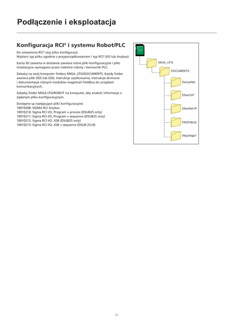
60 61
Podłączenie i eksploatacja
MIGA_CFG
DOCUMENTS
DeviceNet
EtherCAT
PROFIBUS
PROFINET
EtherNet-IP
Config.
Konfiguracja RCI4 i systemu Robot/PLCDo ustawienia RCI4 użyj pliku konfiguracji. Wybierz typ pliku zgodnie z przyporządkowaniem i typ RCI4 (I/O lub Anybus).
Karta SD zawarta w dostawie zawiera różne pliki konfiguracyjne i pliki instalacyjne wymagane przez niektóre roboty i sterowniki PLC.
Załaduj na swój komputer foldery MIGA_CFG/DOCUMENTS. Każdy folder zawiera pliki EDS lub GSD, Instrukcje użytkowania, Instrukcje skrócone i dokumentacje różnych modułów magistrali Fieldbus do urządzeń komunikacyjnych.
Załaduj folder MIGA.CFG/ROBOT na komputer, aby znaleźć informacje o żądanym pliku konfiguracyjnym.
Dostępne są następujące pliki konfiguracyjne:10010208: SIGMA RCI Anybus10010210: Sigma RCI I/O, Program + process (DSUB25 only)10010211: Sigma RCI I/O, Program + sequence (DSUB25 only)10010212: Sigma RCI I/O, JOB (DSUB25 only)10010213: Sigma RCI I/O, JOB + sequence (DSUB 25+9)

62
Dane techniczne RCI4 I/O
ANALOG INPUTSDifferential inputs: 3
Common mode range: ± 20 VDC
Max differential voltage: 10 VDC
Differential Input impedance: 100K Ohm
Sampling frequency: 100 Hz
Max. pulse frequency (square wave): 10 Hz
Digital resolution: 10 Bit
Error: ± 2 % of reading ± 2 digits (20mV)
ANALOG OUTPUTSOutputs: 2
Maximum load: 2K Ohm
Output voltage: 0-10 V
Digital resolution: 12 Bit
Sampling frequency: 97 Hz
Error: ± 2 % of reading ± 5 digits (50mV)
Remarks: cannot be used for certification of the welding process
DIGITAL INPUTSInputs: 16
HIGH level (H): 10-26 VDC
LOW level (L): 0-3 VDC
Input impedance: 5K Ohm
Response time to input changes: 100 ms
DIGITAL OUTPUTSOutputs: 5
LOW level: <1 V
HIGH level: 20-24V from internal supply
Max load: 50 mA
Response time: 100 ms
GENERAL DATAOperating temperature: -10 to 40°C (14 to 104°F)

62 63
Supported Anybus communication interface
General Technical Data
Certification UL, cUL File number E214107 CE - Declaration of Pre-Conformity Emission EN 61000-6-4 EN55011 Radiated emission EN55011 Conducted emission Immunity EN 61000-6-2 EN61000-4-2 Electrostatic discharge EN61000-4-3 Radiated immunity EN61000-4-4 Fast transients/burst EN61000-4-5 Surge immunity EN61000-4-6 Conducted immunity
DeviceNet Vendor ID / Name: 90 (005Ah) / (HMS Industrial Networks) Product Name: ‘Anybus-CompactCom DeviceNet’ ProdTypStr: Generic Device Device Type: 0 (0000h) Product Code: 98 (0062h) (Anybus-CompactCom DeviceNet) Baud rates: 125kbps – 250kbps - 500kbps Major Revision: 2 Minor Revision: 1
The Anybus CompactCom DeviceNet module accepts 11-25 V on the industrial network side of the module. Maximum current consumption at 11-25 V is 36-38 mA/module.
Ethernet IP Vendor ID / Name: 90 (005Ah) / (HMS Industrial Networks) Product Name: ‘Anybus-CC EtherNet/IP’ ProdTypStr: Generic Device Device Type: 0 (0000h) (Generic Device) Product Code: 99 (0063h) (Anybus-CompactCom EtherNet/IP) Assembly instance input: 100 (0064h) Assembly instance output: 150 (0096h) Configuration instance: 1 (0001h) Major Revision: 2 (0002h) Minor Revision: 11 (000Bh)
The Ethernet interface supports 10/100Mbit, full or half duplex operation.
ProfiNET Vendor ID: 268 (010Ch) (HMS Industrial Networks) Device Type: 7 (0007h) (Anybus-CompactCom PROFINET IO) Station Type: ‘ABCC-PRT’
ProfiBus IM Manufacturer ID: 268 (010Ch) (HMS Industrial Networks) IM Order ID: ‘ABCC-DPV1’ IM Profile ID: 62976 (F600h) (Generic Device) IM Profile Specific Type: 4 (0004h) (Communication Module) IM Version: 257 (0101h) IM Supported: 30 (001Eh) (IMO..4 supported)
EtherCAT Vendor ID E000 001Bha (HMS Industrial Networks Secondary Vendor ID, has to be replaced by Vendor ID of end product vendor.) a. For firmware revision 1.02 and later. Product Code 0000 0034h (Anybus CompactCom EtherCAT) Device Name ‘Anybus-CC EtherCAT’ Serial Number (Assigned during manufacturing)
Dane techniczne modułów Anybus
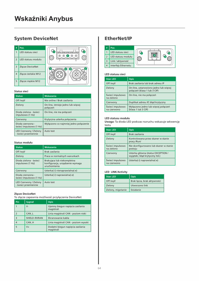
64
Wskaźniki Anybus
EtherNet/IP
# Poz.
1 LED statusu sieci
2 LED statusu modułu
3 Link / aktywność
4 Interfejs Ethernetu
LED statusu sieci
Stan LED Opis
Off /wył/ Brak zasilania lub brak adresu IP
Zielony On-line, ustanowiono jedno lub więcej połączeń (klasa 1 lub 3 CIP)
Świeci impulsowo na zielono
On-line, nie ma połączeń
Czerwony Duplikat adresu IP, błąd krytyczny
Świeci impulsowo na czerwono
Wyłączono jedno lub więcej połączeń (klasa 1 lub 3 CIP)
LED statusu modułuUwaga: Ta dioda LED podczas rozruchu wskazuje sekwencję testu
Stan LED Opis
Off /wył/ Brak zasilania
Zielony Kontrolowana przez skaner w stanie pracy /Run/
Świeci impulsowo na zielono
Nie skonfigurowano lub skaner w stanie postoju
Czerwony Usterka główna (status EXCEPTION /wyjątek/, błąd krytyczny itd.)
Świeci impulsowo na czerwono
Usterka(-i) naprawialna(-e)
LED LINK/Activity
Stan LED Opis
Off /wył/ Brak łącza, brak aktywności
Zielony Utworzono link
Zielony, migotanie Działanie
1 8
System DeviceNet
# Poz.
1 LED statusu sieci
2 LED statusu modułu
3 Złącze DeviceNet
4 Złącze żeńskie M12
5 Złącze męskie M12
Status sieci
Status Wskazania
Off /wył/ Nie online / Brak zasilania
Zielony On-line, istnieje jedno lub więcej połączeń
Dioda zielona - świeci impulsowo (1 Hz)
On-line, nie ma połączeń
Czerwony Krytyczna usterka połączenia
Dioda czerwona - świeci impulsowo (1 Hz)
Wyłączono co najmniej jedno połączenie
LED Czerwony / Zielony - świeci przemiennie
Auto test
Status modułu
Status Wskazania
Off /wył/ Brak zasilania
Zielony Praca w normalnych warunkach
Dioda zielona - świeci impulsowo (1 Hz)
Brakująca lub niekompletna konfiguracja, urządzenie wymaga uruchomienia
Czerwony Usterka(-i) nienaprawialna(-e)
Dioda czerwona - świeci impulsowo (1 Hz)
Usterka(-i) naprawialna(-e)
LED Czerwony / Zielony - świeci przemiennie
Auto test
Złącze DeviceNetTo złącze zapewnia możliwość przyłączenia DeviceNet
Pin Sygnał Opis
1 V- Ujemny biegun napięcia zasilania magistrali
2 CAN_L Linia magistrali CAN - poziom niski
3 SHIELD /EKRAN Ekranowanie kabla
4 CAN_H Linia magistrali CAN - poziom wysoki
5 V+ Dodatni biegun napięcia zasilania magistrali

64 65
Wskaźniki Anybus
PROFIBUS
# Poz.
1 Tryb pracy
2 Status
3 Złącze PROFIBUS
4 Złącze żeńskie M12
5 Złącze męskie M12
Tryb pracy
Status Wskazania
Off /wył/ Nie w trybie online / Brak zasilania
Zielony Wymiana danych
Migające światło zielone Skasować
Dioda czerwona - świeci impulsowo (1 błysk)
Błąd parametryzacji
Dioda czerwona - świeci impulsowo (2 błyski)
Błąd konfiguracji PROFIBUS
Status
Status Wskazania Komentarze
Off /wył/ Nie zostało uruchomione
Status Anybus = ‘SETUP¨’ lub ‘NW_INIT’
Zielony Uruchomione Moduł Anybus pominął status “NW_INIT”
Migające światło zielone
Uruchomiono, wystąpił przypadek diagnostyczny
Ustawiono poszerzony bit diagnostyki
Czerwony Błąd wyjątku Status Anybus = ‘EXCEPTION’
PROFINET IP
# Poz.
1 LED statusu sieci
2 LED statusu modułu
3 LED LINK/Activity
4 Interfejs Ethernetu
LED statusu sieci
Uwaga: Ta dioda LED podczas rozruchu wskazuje sekwencję testu
Stan LED Opis Komentarze
Off /wył/ Offline - Brak zasilania- Brak połączenia z kontrolerem IO
Zielony Online (RUN) /praca online/
- ustanowiono połączenie z kontrolerem IO
- Kontroler IO ma status RUN /praca/
Świeci impulsowo na zielono
Online (STOP)
- ustanowiono połączenie z kontrolerem IO
- Kontroler IO ma status STOP
LED statusu modułuUwaga: Ta dioda LED podczas rozruchu wskazuje sekwencję testu
Stan LED Opis Komentarze
Off /wył/ Połączenie nie uruchomione
Brak zasilania - lub - Moduł ma status “SETUP” lub “NW_INIT”
Zielony Normalna praca
Moduł został przestawiony ze statusu “NW_INIT”
Świeci na zielono - 1 błysk
Zdarzenie(-a) diagnostyczne
Wystąpił przypadek diagnostyczny
Świeci na zielono - 2 błyski
Migotanie Wykorzystywane przez narzędzia inżynieryjne do identyfikacji węzła w sieci
Czerwony Błąd wyjątku Moduł ma status “EXCEPTION”
Świeci na czerwono - 1 błysk
Błąd konfiguracji
Oczekiwana identyfikacja różni się od rzeczywistego stanu identyfikacji
Świeci na czerwono - 2 błyski
Błąd adresu IP Nie ustawiono adresu IP
Świeci na czerwono - 3 błyski
Błąd nazwy stanowiska
Nazwa stanowiska nie została ustawiona
Świeci na czerwono - 4 błyski
Błąd wewnętrzny
Moduł wykrył duży błąd wewnętrzny
LED LINK/Activity
Stan LED Opis Komentarze
Off /wył/ Brak linku Brak łącza, brak komunikacji
Zielony Link Ustawiono łącze Ethernet, brak komunikacji
Zielony, migotanie
Działanie Ustawiono łącze Ethernet, komunikacja poprawna
Interfejs EthernetuInterfejs Ethernet pracuje z prędkością 100 Mbit, przy pełnym dupleksie, z włączoną autonegocjacją - ustawienia domyślne.
1 8

66
Wskaźniki Anybus
EtherCATZłącze EtherCAT
# Poz.
1 LED RUN /praca/
2 LED ERROR /błąd/
3 EtherCAT (port 1)
4 EtherCAT (port 2)
5 Link/Activity (port 1)
6 Link/Activity (port 2)
LED RUN /praca/Dioda LED odzwierciedla status komunikacji CoE (CANopen ponad EtherCAT)
Stan LED Wskazania Opis
Off /wył/ INIT Urządzenie CoE ma status “INIT” (lub brak zasilania)
Zielony PRACUJE Urządzenie CoE ma status “OPERATIONAL”
Zielony migający PRE-OPERATIONAL /przygotowanie do pracy/
Urządzenie CoE ma status “PRE-OPERATIONAL”
Świeci na zielono - 1 błysk
SAFE-OPERATIONAL /bezp.- praca/
Urządzenie CoE ma status ‘SAFE-OPERATIONAL’
Czerwonya (błąd krytyczny) -
a. Jeśli diody RUN i ERR zmienią kolor na czerwony, oznacza to błąd krytyczny, co wymusza przełączenie interfejsu magistrali do fizycznego stanu biernego.
Należy skontaktować się z zespołem pomocy technicznej HMS.
LED ERR Dioda LED wskazuje błędy komunikacji EtherCAT itp.
Stan LED Wskazania Opis
Off /wył/ Brak błędu Brak błędu (lub brak zasilania)
Czerwony, miganie
Nieprawidłowa konfiguracja
Zmiana statusu sygnału otrzymana z modułu master nie jest możliwa z powodu nieprawidłowego ustawienia rejestru lub obiektu
Świeci na czerwono - podwójny błysk
Przekroczenie czasu progu alarmowego aplikacji
Przekroczenie czasu progu alarmowego synchronizacji
Czerwonya Usterka kontrolera aplikacji
Moduł Anybus - status EXCEPTION
a. Jeśli diody RUN i ERR zmienią kolor na czerwony, oznacza to błąd krytyczny, co wymusza przełączenie interfejsu magistrali do fizycznego stanu biernego.
Należy skontaktować się z zespołem pomocy technicznej HMS.
LINK/Activity Diody LED wskazują status i działanie łącza EtherCAT
Stan LED Wskazania Opis
Off /wył/ Brak linku Łącze /link/ nie wykryte (lub nie ma zasilania)
Zielony Łącze /link/ wykryty, brak aktywności
Link wykryty, nie wykryto wymiany sygnału
Zielony, migotanie
Link wykryty, wykryto aktywność
Link wykryty, wykryto wymianę sygnału
6

66 67
5 5
4 4
3 3
2 2
1 1
DD
CC
BB
AA
ANY BUS
CONNECTOR
M1
RCI4
ANYBUS
71613687
74471467
Title
Size
Doc
umen
t Num
ber
Rev
Dat
e:Sh
eet
of
Des
ign
:
Dat
e :
Appr
oved
:
Dat
e :
7886
7005
A
RC
I4 A
NYB
US
BO
KS
MIG
ATRO
NIC
A/S
Agge
rsun
dvej
33
DK-
9690
Fje
rrits
lev
Tlf:
(+45
) 96
500
600
ww
w.m
igat
roni
c.dk
A4
11
Tues
day,
Feb
ruar
y 05
, 201
9
BPO
05-0
2-20
19
JBI
05-0
2-20
19
Title
Size
Doc
umen
t Num
ber
Rev
Dat
e:Sh
eet
of
Des
ign
:
Dat
e :
Appr
oved
:
Dat
e :
7886
7005
A
RC
I4 A
NYB
US
BO
KS
MIG
ATRO
NIC
A/S
Agge
rsun
dvej
33
DK-
9690
Fje
rrits
lev
Tlf:
(+45
) 96
500
600
ww
w.m
igat
roni
c.dk
A4
11
Tues
day,
Feb
ruar
y 05
, 201
9
BPO
05-0
2-20
19
JBI
05-0
2-20
19
Title
Size
Doc
umen
t Num
ber
Rev
Dat
e:Sh
eet
of
Des
ign
:
Dat
e :
Appr
oved
:
Dat
e :
7886
7005
A
RC
I4 A
NYB
US
BO
KS
MIG
ATRO
NIC
A/S
Agge
rsun
dvej
33
DK-
9690
Fje
rrits
lev
Tlf:
(+45
) 96
500
600
ww
w.m
igat
roni
c.dk
A4
11
Tues
day,
Feb
ruar
y 05
, 201
9
BPO
05-0
2-20
19
JBI
05-0
2-20
19
M1 Microfit8s1 2 3 4 5 6 7 8
CAN CONNECT
1234
5 6 789
1+5
5V2
+55V
3G
ND
_+55
V4
GN
D_+
55V
5+1
1V_C
AN6
MIG
ANET
0_H
7M
IGAN
ET0_
L8
GN
D_C
AN9
NC
+55V
+55V
GN
D_+
55V
GN
D_+
55V
+11V
_CAN
MIG
ANET
0_H
MIG
ANET
0_L
GN
D_C
AN

68
5 5
4 4
3 3
2 2
1 1
DD
CC
BB
AA
RCI4 I/O71613641
17200193
17200193
74471467
Title
Size
Doc
umen
t Num
ber
Rev
Dat
e:Sh
eet
of
Des
ign
:
Dat
e :
Appr
oved
:
Dat
e :
7886
7006
A
RC
I4 I/
O B
OK
S
MIG
ATRO
NIC
A/S
Agge
rsun
dvej
33
DK-
9690
Fje
rrits
lev
Tlf:
(+45
) 96
500
600
ww
w.m
igat
roni
c.dk
A4
11
Tues
day,
Feb
ruar
y 05
, 201
9
BPO
05-0
2-20
19
JBI
05-0
2-20
19
Title
Size
Doc
umen
t Num
ber
Rev
Dat
e:Sh
eet
of
Des
ign
:
Dat
e :
Appr
oved
:
Dat
e :
7886
7006
A
RC
I4 I/
O B
OK
S
MIG
ATRO
NIC
A/S
Agge
rsun
dvej
33
DK-
9690
Fje
rrits
lev
Tlf:
(+45
) 96
500
600
ww
w.m
igat
roni
c.dk
A4
11
Tues
day,
Feb
ruar
y 05
, 201
9
BPO
05-0
2-20
19
JBI
05-0
2-20
19
Title
Size
Doc
umen
t Num
ber
Rev
Dat
e:Sh
eet
of
Des
ign
:
Dat
e :
Appr
oved
:
Dat
e :
7886
7006
A
RC
I4 I/
O B
OK
S
MIG
ATRO
NIC
A/S
Agge
rsun
dvej
33
DK-
9690
Fje
rrits
lev
Tlf:
(+45
) 96
500
600
ww
w.m
igat
roni
c.dk
A4
11
Tues
day,
Feb
ruar
y 05
, 201
9
BPO
05-0
2-20
19
JBI
05-0
2-20
19
M2
3M34
BW
1 2 3 4 5 6 7 8 9 10 11 12 13 14 15 16 17 18 19 20 21 22 23 24 25 26 27 28 29 30 31 32 33 34
DSU
B 9
1A 2A 3A 4A 5A 6A 7A 8A 9A
M1 Microfit8s1 2 3 4 5 6 7 8
CAN CONNECT
1234
5 6 789
1+5
5V2
+55V
3G
ND
_+55
V4
GN
D_+
55V
5+1
1V_C
AN6
MIG
ANET
0_H
7M
IGAN
ET0_
L8
GN
D_C
AN9
NC
DSU
B 25
1A 2A 3A 4A 5A 6A 7A 8A 9A 10A
11A
12A
13A
14A
15A
16A
17A
18A
19A
20A
21A
22A
23A
24A
25A
+55V
+55V
GN
D_+
55V
GN
D_+
55V
+11V
_CAN
MIG
ANET
0_H
MIG
ANET
0_L
GN
D_C
AN
ANAL
OG
_IN
5AN
ALO
G_I
N4
GN
DD
IGIT
AL_O
UT4
DIG
ITAL
_OU
T3G
ND
DIG
ITAL
_IN
15D
IGIT
AL_I
N14
DIG
ITAL
_IN
11D
IGIT
AL_I
N10
DIG
ITAL
_IN
9D
IGIT
AL_I
N8
DIG
ITAL
_IN
7D
IGIT
AL_I
N6
DIG
ITAL
_IN
5D
IGIT
AL_I
N4
DIG
ITAL
_IN
3D
IGIT
AL_I
N2
DIG
ITAL
_IN
1D
IGIT
AL_I
N0
GN
DD
IGIT
AL_O
UT2
DIG
ITAL
_OU
T1D
IGIT
AL_O
UT0
GN
DAN
ALO
G_I
N3
ANAL
OG
_IN
2AN
ALO
G_I
N1
ANAL
OG
_IN
0G
ND
ANAL
OG
_OU
T1AN
ALO
G_O
UT0
ANAL
OG
_OU
T0AN
ALO
G_O
UT1
GN
DAN
ALO
G_I
N0
ANAL
OG
_IN
1AN
ALO
G_I
N2
ANAL
OG
_IN
3G
ND
DIG
ITAL
_OU
T0D
IGIT
AL_O
UT1
DIG
ITAL
_OU
T2G
ND
DIG
ITAL
_IN
0D
IGIT
AL_I
N1
DIG
ITAL
_IN
2D
IGIT
AL_I
N3
DIG
ITAL
_IN
4D
IGIT
AL_I
N5
DIG
ITAL
_IN
6D
IGIT
AL_I
N7
DIG
ITAL
_IN
8D
IGIT
AL_I
N9
DIG
ITAL
_IN
10D
IGIT
AL_I
N11
DIG
ITAL
_IN
12
DIG
ITAL
_IN
13D
IGIT
AL_I
N14
DIG
ITAL
_IN
15G
ND
DIG
ITAL
_OU
T3D
IGIT
AL_O
UT4
GN
DAN
ALO
G_I
N4
ANAL
OG
_IN
5
DIG
ITAL
_IN
12D
IGIT
AL_I
N13

76
DENMARK:
Main officeSVEJSEMASKINEFABRIKKEN MIGATRONIC A/SAggersundvej 33, DK-9690 Fjerritslev, DenmarkTel. +45 96 500 600, www.migatronic.com
MIGATRONIC EUROPE:
Great BritainMIGATRONIC WELDING EQUIPMENT LTD21 Jubilee Drive, Belton Park, LoughboroughGB-Leicestershire LE11 5XS, Great BritainTel. +44 01509/267499, www.migatronic.co.uk
FranceMIGATRONIC EQUIPEMENT DE SOUDURE S.A.R.L. Parc Avenir II, 313 Rue Marcel Merieux FR-69530 Brignais, France Tel. +33 04 78 50 65 11, www.migatronic.fr
ItalyMIGATRONIC s.r.l. IMPIANTI PER SALDATURA Via Dei Quadri 40, IT-20871 Vimercate (MB), Italy Tel. +39 039 9278093, www.migatronic.it
NorwayMIGATRONIC NORGE AS Industriveien 6, N-3300 Hokksund, Norway Tel. +47 32 25 69 00, www.migatronic.no
Czech RepublicMIGATRONIC CZ a.s. Tolstého 451, CZ-415 03 Teplice 3, Czech Republic Tel. +420 411 135 600, www.migatronic.cz
HungaryMIGATRONIC KERESKEDELMI KFT. Szent Miklós u. 17/a, H-6000 Kecskemét, Hungary Tel. +36 76 505 969 www.migatronic.hu
MIGATRONIC ASIA:
ChinaSUZHOU MIGATRONIC WELDING TECHNOLOGY CO. LTD #4 FengHe Road, Industrial Park, CH-SuZhou, ChinaTel. +86 0512-87179800, www.migatronic.cn
MIGATRONIC AUTOMATION A/SKnøsgårdvej 112, DK-9440 Aabybro, DenmarkTel. +45 96 96 27 00, www.migatronic-automation.dk
FinlandMIGATRONIC OY PL 105, FI-04301 Tuusula, Finland Tel. +358 0102 176 500, www.migatronic.fi
HollandMIGATRONIC NEDERLAND B.V. Hallenweg 34, NL-5683 CT Best, Holland Tel. +31 499 37 50 00, www.migatronic.nl
SwedenMIGATRONIC SVETSMASKINER ABNääs Fabriker, Box 5015,S-448 50 Tollered, Sweden Tel. +46 031 44 00 45, www.migatronic.se
GermanyMIGATRONIC SCHWEISSMASCHINEN GMBH Sandusweg 12, D-35435 Wettenberg-Launsbach, Germany Tel. +49 0641/98284-0, www.migatronic.de
IndiaMIGATRONIC INDIA PRIVATE LTD.No.22 & 39/20H Sowri Street, IN-Alandur, Chennai – 600 016, IndiaTel. +91 44 2233 0074 www.migatronic.in