Numerical Simulation of Welding Thin Titanium Sheets
9
Numerical simulation of welding thin titanium sheets Piotr Lacki 1, a , Konrad Adamus 1,b 1 Czestochowa University of Technology, ul. J.H. Dąbrowskiego 69, Częstochowa 42-201, Poland a [email protected], b [email protected] Keywords: FEM simulation, titanium sheets, titanium Grade 2, titanium Grade 5, electron beam welding. Abstract. Different titanium grades are used in aircraft construction because of titanium’s unique properties. These materials are mostly joined by different welding methods. Electron beam welding technology is often used in the aircraft industry to join structural elements made of titanium alloys. The goal of the work is a numerical analysis of the electron beam welding process applied to joining thin titanium sheets. The analysis was performed using finite element method, FEM. Temperature distribution, size of heat affected zone (HAZ), depth and width of fusion zone were determined for the assumed heat source model. Thermo-mechanical (TMC) simulation of the electron beam welding process using FEM is presented in the paper. The joining of two sheets, one made of commercially pure titanium Grade 2 and the other made of titanium alloy Grade 5 (Ti6Al4V), is analysed in the work. For the sheet welding process distributions of temperature, effective stress, and sheet deformation were calculated. Introduction. Titanium has attractive mechanical properties [1]. Low density and high strength are characteristic of titanium and its alloys. A combination of these properties is widely used in technology although, in practice, plastic forming of titanium, especially its alloys poses many problems. In [2,3,4] some advantages and disadvantages of titanium as the material used for the drawn-parts were presented. Sheet-titanium forming as an essential component of modern industry allowing for production of drawn-parts used in the aerospace, automotive and construction industries was discussed. The high corrosion resistance of titanium is the main reason for its wide application in the chemical industry and medicine. The experimental data of mechanical titanium properties, which are necessary in numerical simulations, were given. Sheets made of commercially pure titanium (e.g. Grade1 or Grade 2) and titanium alloys (e.g. Grade 5 or Grade 9) are often used in industry. The components produced from titanium sheets such as casings, car body parts or aircraft parts require joining operations. The joined sheets are characterized by different geometry or material properties, the so called tailor welded blanks (TWB), are being increasingly used in industry. The quality of weld in TWB is an important factor which can influence the quality of the deep drawing process. An accurate description of weld behaviour during the forming process is a difficult task. The increase of temperature in the heat affected zone (HAZ) during the welding process causes changes in material’s mechanical properties. A tension test doesn’t provide enough data to identify the sheet mechanical properties, necessary for a simulation, within the volume of material corresponding to HAZ. More detailed experiments and numerical simulations are required. In [5] the comprehensive studies on the weld quality in TWB were presented. In [6] different methods for the measurement of TWB mechanical properties within a heat affected zone were suggested. These methods were based both on the experimental studies, and the combined experimental and numerical procedures. The results of the uniaxial tensile test and the microhardness measurements were given. Based on the tests conducted, the stress-strain relationships were given Electron beam welding, EBW, is one of the joining methods used for titanium. EBW is a fusion welding process that utilizes electrons as a source of heat [7]. It is very efficient and precise welding technique thus its application in industrial processes is increasing, [8]. The advantage of EBW Key Engineering Materials Vol. 549 (2013) pp 407-414 Online available since 2013/Apr/24 at www.scientific.net © (2013) Trans Tech Publications, Switzerland doi:10.4028/www.scientific.net/KEM.549.407 All rights reserved. No part of contents of this paper may be reproduced or transmitted in any form or by any means without the written permission of TTP, www.ttp.net. (ID: 130.194.20.173, Monash University Library, Clayton, Australia-31/08/13,17:23:33)
Transcript of Numerical Simulation of Welding Thin Titanium Sheets
Numerical simulation of welding thin titanium sheets
Piotr Lacki1, a, Konrad Adamus1,b 1Czestochowa University of Technology, ul. J.H. Dąbrowskiego 69, Częstochowa 42-201, Poland
Keywords: FEM simulation, titanium sheets, titanium Grade 2, titanium Grade 5, electron beam welding.
Abstract. Different titanium grades are used in aircraft construction because of titanium’s unique
properties. These materials are mostly joined by different welding methods. Electron beam welding
technology is often used in the aircraft industry to join structural elements made of titanium alloys.
The goal of the work is a numerical analysis of the electron beam welding process applied to joining
thin titanium sheets. The analysis was performed using finite element method, FEM. Temperature
distribution, size of heat affected zone (HAZ), depth and width of fusion zone were determined for
the assumed heat source model. Thermo-mechanical (TMC) simulation of the electron beam
welding process using FEM is presented in the paper. The joining of two sheets, one made of
commercially pure titanium Grade 2 and the other made of titanium alloy Grade 5 (Ti6Al4V), is
analysed in the work. For the sheet welding process distributions of temperature, effective stress,
and sheet deformation were calculated.
Introduction. Titanium has attractive mechanical properties [1]. Low density and high strength are
characteristic of titanium and its alloys. A combination of these properties is widely used in
technology although, in practice, plastic forming of titanium, especially its alloys poses many
problems. In [2,3,4] some advantages and disadvantages of titanium as the material used for the
drawn-parts were presented. Sheet-titanium forming as an essential component of modern industry
allowing for production of drawn-parts used in the aerospace, automotive and construction
industries was discussed. The high corrosion resistance of titanium is the main reason for its wide
application in the chemical industry and medicine. The experimental data of mechanical titanium
properties, which are necessary in numerical simulations, were given.
Sheets made of commercially pure titanium (e.g. Grade1 or Grade 2) and titanium alloys (e.g.
Grade 5 or Grade 9) are often used in industry. The components produced from titanium sheets such
as casings, car body parts or aircraft parts require joining operations. The joined sheets are
characterized by different geometry or material properties, the so called tailor welded blanks
(TWB), are being increasingly used in industry. The quality of weld in TWB is an important factor
which can influence the quality of the deep drawing process. An accurate description of weld
behaviour during the forming process is a difficult task. The increase of temperature in the heat
affected zone (HAZ) during the welding process causes changes in material’s mechanical properties.
A tension test doesn’t provide enough data to identify the sheet mechanical properties, necessary for
a simulation, within the volume of material corresponding to HAZ. More detailed experiments and
numerical simulations are required. In [5] the comprehensive studies on the weld quality in TWB
were presented. In [6] different methods for the measurement of TWB mechanical properties within
a heat affected zone were suggested. These methods were based both on the experimental studies,
and the combined experimental and numerical procedures. The results of the uniaxial tensile test
and the microhardness measurements were given. Based on the tests conducted, the stress-strain
relationships were given
Electron beam welding, EBW, is one of the joining methods used for titanium. EBW is a fusion
welding process that utilizes electrons as a source of heat [7]. It is very efficient and precise welding
technique thus its application in industrial processes is increasing, [8]. The advantage of EBW
Key Engineering Materials Vol. 549 (2013) pp 407-414Online available since 2013/Apr/24 at www.scientific.net© (2013) Trans Tech Publications, Switzerlanddoi:10.4028/www.scientific.net/KEM.549.407
All rights reserved. No part of contents of this paper may be reproduced or transmitted in any form or by any means without the written permission of TTP,www.ttp.net. (ID: 130.194.20.173, Monash University Library, Clayton, Australia-31/08/13,17:23:33)
technology is its low heat input into the weld that translates into a low deformation of welded
components. Wang [9] analysed the extension of electron beam welding with electron beam
scanning for the joining of titanium Grade 5. It was shown that the application of electron beam
scanning allows for controlling titanium Grade 5 microstructure. Finite element method (FEM) is an
effective way to predict properties of the welded parts and weld based on the process control
parameters [10,11,12]. The examples of using FEM method to simulate the welding process for
Inconel 706 parts were presented in [13,14]. In [15,16] authors using this method studied the weld
pool characteristic and its relation to the welding process parameters such as: welding speed,
electron beam power and thickness of welded material. A different approach to the study of the
weld pool was adopted in [17]. An interaction between keyhole and welding pool during laser
welding using numerical simulations was analysed. The keyhole shape was dependent on the
surface tension and the recoil force. The numerical model was developed based on the Fluent
system which is a computational fluid dynamics (CFD) software. Welding of titanium and its alloys
requires appropriate selection of the welding method due to high chemical activity and susceptibility
to gas (nitrogen, oxygen and hydrogen) absorption at temperatures above 500oC. This limits the
choice of available welding technologies. In order to avoid undesirable changes in a material
structure titanium welding requires inert gas protection such as argon, or a vacuum. EBW
technology is frequently applied to the joining of titanium components.
Goal of the work. The numerical analysis of electron beam welding of thin titanium sheets is the
main goal of this study. Based on the numerical analysis temperature distribution, size of heat
affected zone (HAZ), and the depth and width of fusion zone were determined for the assumed
model of the heat source.
This study presents the thermo-mechanical (TMC) simulation of the electron beam welding
process using the finite element method (FEM). The joint between two sheets made of
commercially pure titanium Grade 2 and titanium alloy Grade 5 (Ti6Al4V) was considered. Sheets
of type tailor-welded blanks – TWB combine good drawability of one sheet with the high strength
of the other sheet. A well-designed joint ensures beneficial properties of TWB sheets.
In the paper the calculation results for the following EBW parameters were given: accelerating
voltage of 50 kV, beam current of 4 mA, and welding speed of 20 mm/s. The electron beam was
focused at the top surface of the sheets.
On the basis of the numerical calculations a heat affected zone, a degree of sheet deformation and
residual stresses after welding were determined. The calculation results were compared against the
actual experiment results.
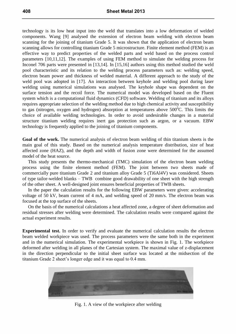
Experimental test. In order to verify and evaluate the numerical calculation results the electron
beam welded workpiece was used. The process parameters were the same both in the experiment
and in the numerical simulation. The experimental workpiece is shown in Fig. 1. The workpiece
deformed after welding in all planes of the Cartesian system. The maximal value of z-displacement
in the direction perpendicular to the initial sheet surface was located at the midsection of the
titanium Grade 2 sheet’s longer edge and it was equal to 0.4 mm.
Fig. 1. A view of the workpiece after welding
408 Sheet Metal 2013

Model description. The numerical model was built using the Finite Element Method extensively
described in the literature [18,19,20]. The analysis was performed using the ADINA System based
on FEM. The model takes into account changes in stresses as a function of temperature. Such a
solution requires a thermo-mechanical model. The numerical model uses 8-node hexahedral finite
elements. The model comprises 24,552 finite elements which correspond to 38,112 nodes. Due to
the highly nonlinear and non-stationary nature of the problem, 4,800 time steps were used in the
calculations. The value of a single time step was 0.002 s. The total time of the simulated process
was 603.6 s where the welding time was 8 s and the remaining time corresponded to the cooling of
the sheets in the air. The length of the welding trajectory was 160 mm. The numerical model takes
into account fixing of the sheets using a clamping device. This was achieved by taking away degrees
of freedom in the clamping area.
Thermal model. A flat three-dimensional thermal model of heat transfer described by Fourier
law was used in the analysis. It was assumed that the initial temperature of the sheets is 20oC.
Internal heat was applied to consecutive volumes of material in order to simulate a moving electron
beam. The volume of material where the heat is produced moves through the mesh with a step equal
to the length of element edge. The following material data were assumed in the model:
- for Grade 2 titanium: thermal conductivity k=20.8 W/mK, specific heat of 523 J/kgK and
density of 4510 kg/m3,
- for Grade 5 titanium: thermal conductivity k=6.7 W/mK, specific heat of 526 J/kgK, and
density of 4430 kg/m3
Heat exchange to the environment was assumed on the sheet surface.
Mechanical model. A three-dimensional stress state was assumed in the static mechanical
analysis. An elastic-plastic Prandtl model without hardening was applied to the description of
material behavior. The assumed mechanical properties of Grade 2 and Grade 5 titanium as a
function of temperature are shown in Table 1.
Table 1. Mechanical properties of Grade 2 and Grade 5 titanium versus temperature
Temperature
[oC]
Young’s
Modulus
[GPa]
Poisson’s ratio Yield point
[MPa]
Modulus of
strain hardening
[MPa]
Coefficient of
linear expansion
[10-6
/K]
Grade
5
Grade
2
Grade
5
Grade
2
Grade
5
Grade
2
Grade
5
Grade
2
Grade
5
Grade
2
100.0 99.90 102.4 0.342 0.37 813 300 83.81 115 8.66 8.41
200.0 94.66 94.8 0.342 0.37 726 230 87.62 115 9.26 8.88
300.0 89.42 87.2 0.342 0.37 639 200 91.43 115 9.86 9.35
400.0 84.18 79.6 0.342 0.37 553 170 95.24 115 10.46 10.30
500.0 78.94 72.0 0.342 0.37 466 140 99.05 115 11.06 10.77
600.0 73.70 64.4 0.342 0.37 379 110 102.86 115 11.66 11.25
700.0 68.46 56.8 0.342 0.37 293 80 106.67 115 12.26 11.72
800.0 63.22 49.2 0.342 0.37 206 50 110.48 115 12.86 12.19
900.0 57.98 41.6 0.342 0.37 119 20 114.29 115 13.46 12.66
1000.0 52.74 36.1 0.342 0.37 60 20 118.10 115 14.06 13.14
1550.0 6.00 6.0 0.342 0.37 60 20 21.72 115 17.66 15.74
1600.0 5.00 5.0 0.342 0.37 60 20 12.96 115 17.98 15.98
The geometry and mesh of the welded sheets. In the analysis both Grade 2 and Grade 5
titanium sheets have the same thickness of 0.8 mm and length of 160 mm. The width of titanium
Grade 2 sheet is 28.5 mm and the width of the titanium Grade 5 sheet is 26 mm. The overall view of
Key Engineering Materials Vol. 549 409

titanium sheets’ geometry is presented in Fig. 2 (a), a mesh for a 25-mm long trajectory is shown in
Fig. 2 (b) and the magnified view of the mesh around the welding trajectory is presented in Fig. 2
(c). The beginning of the welding trajectory is located at the origin of a coordinate system and a heat
source moves along y axis. The orientation of the sheets in the following figures is the same, i.e.
titanium Grade 2 sheet is located at the side of xy plane corresponding to negative x values and
titanium Grade 5 sheet is located at the side of xy plane corresponding to positive x values.
Fig. 2. FEM mesh (a) the overall view of the titanium sheets’ geometry (b) the view of mesh for a
25-mm long welding trajectory (c) the magnified mesh around the welding trajectory
Fig. 3. The movement of the heat source through the FEM mesh corresponding to a short
welding trajectory for times t1 and t2
410 Sheet Metal 2013

The heat source moves through the mesh. Fig. 3 presents only these elements where heat is
produced during the welding process. The heat source is denoted with a black color and its position
is presented for two moments in time: t1 and t2. The heat source is built from two volumes in shape
of a cuboid. The volumes are stacked on each other as presented in Fig. 3. The mesh is generated in
such a way that elements are either fully inside or fully outside a heat source volume. The size and
power density of the heat source volumes define the heat source. The heat source was calibrated in
order to obtain consistency between the actual and calculated shapes of the fusion zone. As a result
of calibration process, the top heat source segment was assigned the power density of 512·109 W/m
3
and the bottom heat source segment was assigned the power density of 256·109 W/m
3. The total
power of the calibrated heat source was equal to 164 W and the electron beam power was equal to
200 W. Not all the beam power is converted into heat inside a material. The loss of heat source
power is caused among others by reflection of electrons and emission of X-rays [8]. The loss of
power is represented by an efficiency factor η which in the analyzed case was equal to 82%. Thus
the total power generated by the heat source equals the product of the beam power and the
efficiency factor.
Numerical calculation results. Temperature distribution at a welding time of 6.4 s is shown in
Fig. 4. It can be seen that isotherms are not symmetrical with respect to the welding trajectory. This
is due to the different thermal conductivity of the welded sheets. An asymmetry of temperature
distribution causes different thermal expansion of the sheets and thus the increase in residual
stresses. The maximal calculated temperature is in the middle of the weld pool and equals
Tmax=4195°C. This temperature may deviate from the real temperature because the calculated
temperature strongly depends on the resolution of the finite element mesh and time steps.
Fig. 4. The temperature distribution, C, on the welded workpiece surface at time 6.4 s
The numerical calculations on the basis of the assumed model give valuable information on the
analysed process. This information is difficult to obtain in other ways. To date, the determination of
residual stresses after welding is one of the most difficult tasks. Residual stresses represented as
effective stresses appear already in the first seconds of the welding process and grow as the process
continues. The maximal effective stress in the first second of the process is 391 MPa. Fig. 5 shows
the distribution of effective stresses at time 6.4s from the beginning of the welding operation.
In this case, the maximal stresses increase up to 711 MPa. In the area of the weld pool stresses
are small due to the very low titanium yield point at such a temperature. Stresses increase as the
metal cools. According to Fig. 5 the highest effective stresses occur at the start point of the welding
trajectory and gradually decrease in the direction of the weld pool.
Key Engineering Materials Vol. 549 411
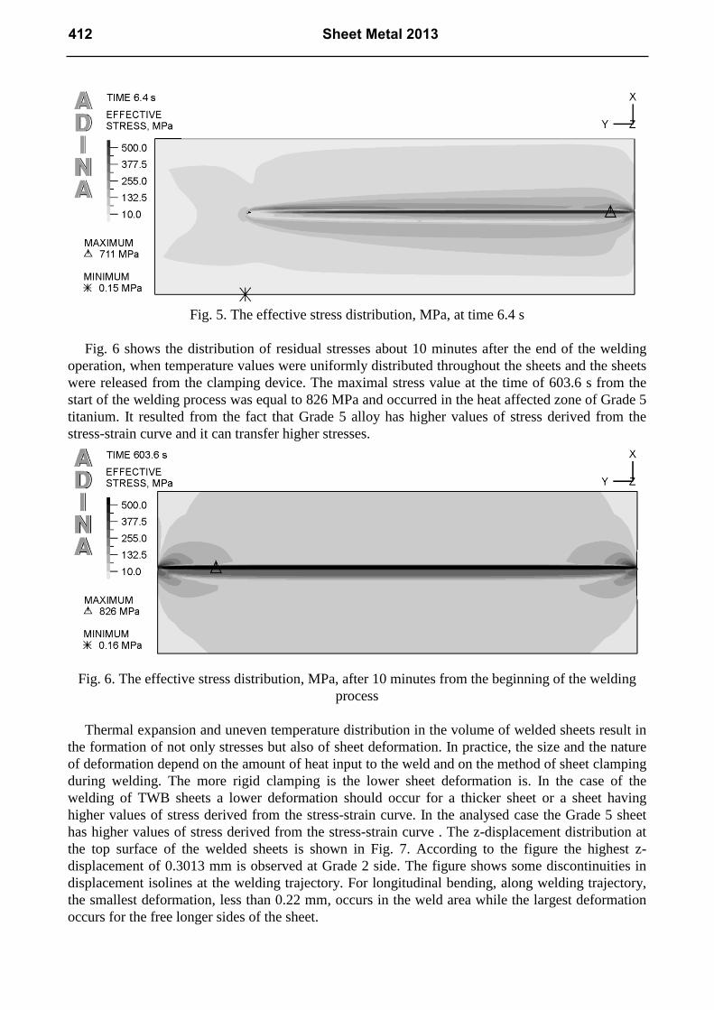
Fig. 5. The effective stress distribution, MPa, at time 6.4 s
Fig. 6 shows the distribution of residual stresses about 10 minutes after the end of the welding
operation, when temperature values were uniformly distributed throughout the sheets and the sheets
were released from the clamping device. The maximal stress value at the time of 603.6 s from the
start of the welding process was equal to 826 MPa and occurred in the heat affected zone of Grade 5
titanium. It resulted from the fact that Grade 5 alloy has higher values of stress derived from the
stress-strain curve and it can transfer higher stresses.
Fig. 6. The effective stress distribution, MPa, after 10 minutes from the beginning of the welding
process
Thermal expansion and uneven temperature distribution in the volume of welded sheets result in
the formation of not only stresses but also of sheet deformation. In practice, the size and the nature
of deformation depend on the amount of heat input to the weld and on the method of sheet clamping
during welding. The more rigid clamping is the lower sheet deformation is. In the case of the
welding of TWB sheets a lower deformation should occur for a thicker sheet or a sheet having
higher values of stress derived from the stress-strain curve. In the analysed case the Grade 5 sheet
has higher values of stress derived from the stress-strain curve . The z-displacement distribution at
the top surface of the welded sheets is shown in Fig. 7. According to the figure the highest z-
displacement of 0.3013 mm is observed at Grade 2 side. The figure shows some discontinuities in
displacement isolines at the welding trajectory. For longitudinal bending, along welding trajectory,
the smallest deformation, less than 0.22 mm, occurs in the weld area while the largest deformation
occurs for the free longer sides of the sheet.
412 Sheet Metal 2013

Fig. 7. The values of z-displacement, mm, which characterize the deformation of the welded sample
Summary
Based on the carried out numerical calculations it can be stated that titanium welded sheets undergo
deformation as a result of heat generation during welding. The degree of deformation depends on
the amount of heat input to the weld. There is the increase in sheet deformation when the value of
energy input grows. The experimental results are in qualitative agreement with the numerical
calculation results. The actual value of the maximal z-displacement was equal to 0.4 mm and the
calculated value of the maximal z-displacement was equal to 0.3 mm. In both cases the maximal
z-displacement was located at the midsection of the longer edge of the titanium Grade 2 sheet.
For an accelerating voltage of 50kV, welding speed of 20 mm/s and beam current of 4 mA the
maximal calculated temperature is equal to 4195oC.
The calculated residual stresses in EBW joint reach the maximal value of 826 MPa and occur in
the heat affected zone of Grade 5 titanium.
Acknowledgements. Financial support of Structural Funds in the Operational Programme -
Innovative Economy (IE OP) financed from the European Regional Development Fund - Project
"Modern material technologies in aerospace industry", Nr POIG.01.01.02-00-015/08-00 is gratefully
acknowledged.
References
[1] A. Bylica, J. Sieniawski: Tytan i jego stopy (PWN, Warszawa, Poland 1985 in Polish).
[2] J. Adamus: Arch. Metall. Mater. Vol. 54/3 (2009), p. 705.
[3] J. Adamus, P. Lacki, W. Więckowski: Arch. Metall. Mater. Vol. 56 Issue 2 (2011), p. 431.
[4] J. Adamus, P. Lacki: Comp. Mater. Sci. Vol. 50 (2011), p. 1305.
[5] V. Ciubotariu, G. Brabie: Arch. Civ. Mech. Eng. Vol. 11, Issue 4 (2011), p. 811.
[6] J. Rojek, M. Hyrcza-Michalska, A. Bokota, W. Piekarska: Arch. Civ. Mech. Eng. Vol. 12, Issue
2 (2012), p. 156.
[7] S.-C. Wu, K.-H. Tseng, H.-C. Wen, M.-J. Wu, C.-P. Chou, Appl. Surf. Sci., Vol. 264 (2013),
p. 45-51
[8] H. Schultz: Electron beam welding, Woodhead Publishing, Abington, 1994.
[9] S. Wang, X. Wu, Mater. Design, Vol. 36 (2012), p. 663–670
Key Engineering Materials Vol. 549 413

[10] W. Piekarska, M. Kubiak, A. Bokota: Arch. Metall. Mater., Vol. 56 Issue 2, (2011), p.409
[11] W. Piekarska, M. Kubiak: Int. J. Heat. Mass. Tran., Vol. 54 Issue 23-24, (2011) p. 4966
[12] W. Piekarska, M. Kubiak, J. Therm. Anal. Calorim., Vol. 110 Issue 1, (2012) p. 159
[13] P. Ferro, A. Zambon, F. Bonollo: Mater. Sci. Eng. A, Vol. 392 (2005) , p. 94.
[14] P. Lacki, K. Adamus, K. Wojsyk, M. Zawadzki: Key Eng. Mat. Vol. 473 (2011) p. 540.
[15] P. Lacki, K. Adamus: Comput. Struct.Vol. 89 (2011), p. 977.
[16] P. Lacki, K. Adamus, K. Wojsyk, M. Zawadzki, Z. Nitkiewicz: Arch. Metall. Mater. Vol. 56
Issue 2 (2011), p. 455.
[17] J. Rońda, A. Siwek: Arch. Civ. Mech. Eng. Vol. 11, Issue 3 (2011), p. 739.
[18] O.C. Zienkiewicz: Metoda Elementów Skończonych (Arkady, Warszawa 1972 in Polish).
[19] K.J. Bathe: Finite Element Procedures (Prentice-Hall Inc., New Jersey, 1996).
[20] T. Pyttel: Finite Element Course (ESIGmbH, Eschborn, 2002).
414 Sheet Metal 2013

Sheet Metal 2013 10.4028/www.scientific.net/KEM.549 Numerical Simulation of Welding Thin Titanium Sheets 10.4028/www.scientific.net/KEM.549.407