
Numerical comparative analysis of the combustion process ... · 2. Podstawy teoretyczne obliczeń...
9
62 COMBUSTION ENGINES, No. 1/2012 (148) Ryszard MICHAŁOWSKI Krzysztof MIKSIEWICZ Marcin TKACZYK Numerical comparative analysis of the combustion process in an engine powered by CNG This paper contains the analysis of Compressible Natural Gas combustion process in engine dedicated to diesel oil. The analysis was performed on the basis of the numerical results of two systems for methane dosing. The first simulation considers the CNG delivery into the suction manifold, and subsequent production of air-fuel mixture as well as separate combustion model of a homogenous mixture. The second simulation comprises a numerical application of the fuel injec- tion directly into the combustion chamber. Therefore it is also a simulation of a combustion process. Among the numerical results conducted with the aid of Computational Fluid Dynamics the following parameters were selected for the combustion qualitative evaluation in terms of mechanical, heat and flow properties: fields of pressure and temperature, mass fraction of the fuel and turbulence intensity. All test were conducted on the engine adopted to be fed with CNG. Key word: combustion engines, Compresible Natural Gas, Computational Fluid Dynamic Numeryczna analiza porównawcza procesów spalania w silnikach zasilanych CNG W artykule przedstawiono analizę procesów spalania CNG w silniku oryginalnie zaprojektowanym do spalania oleju napędowego. Analizę przeprowadzono na podstawie wyników badań numerycznych dwóch systemów dozowania metanu. Pierwszy obejmuje symulację dozowania CNG do kolektora dolotowego, następnie wytworzenie mieszanki powietrzno- paliwowej oraz odrębny model spalania mieszanki homogenicznej. Drugi system to numeryczna aplikacja wtrysku metanu bezpośrednio do komory spalania, a w konsekwencji symulacja procesu spalania. Spośród wyników badań numerycznych CFD do oceny jakościowej spalania pod kątem właściwości mechanicznych cieplnych i przepływowych wybrano takie parametry procesu, jak: pole ciśnienia i temperatury, udział masowy paliwa oraz intensywność turbulencji; w silniku adaptowanym do zasilania CNG. Słowa kluczowe: silniki spalinowe, gaz ziemny, modelowanie numeryczne 1. Introduction A piston combustion engine is a heat (thermodynamic) ma- chine, in which chemical energy of fuel is converted into heat energy. This in turn is converted into mechanical energy. Obtaining best performance index of a combustion en- gines was one of the main priority for the constructors on the early ears of the engines inception. Initially, it was manifested by the desire to increase overall power and efficiency. Over time, these efforts have become more sophisticated and dealt with operating parameters. However the basic problem which is remains improving the process of cylinder filling with working medium [8]. Intake system plays an important role in the process of an internal combustion engine cylinder filling, therefore there is a need to express it in numerical way. By describing the phe- nomenon occurring within the intake systems. All approaches to express the process of cylinder filling numerically based on simplified assumption was characterized by low conform- ity with results of practical verification. The complexity of the equations governing the mass, energy and momentum conservation laws interfered obtaining correct computation results [7]. However, the development of numerical meth- ods combined with the rapid progress of digital computers has enabled the approximate solution and consequently the simulation of flow in the intake systems. 1. Wstęp Tłokowy silnik spalinowy jest maszyną cieplną (ter- modynamiczną), w której energia chemiczna paliwa jest zamieniana na energię cieplną, a ta z kolei na energię me- chaniczną. Uzyskanie jak najlepszych wskaźników pracy silnika spalinowego skupiało uwagę konstruktorów od pierwszych lat jego powstania. Początkowo wyrażało się to dążeniem do zwiększenia mocy i sprawności ogólnej silnika. W miarę upływu czasu dążenia te stały się bardziej wyrafinowane i dotyczyły większej liczby parametrów roboczych silnika. Problemami pozostały jednak nadal: poprawa napełnienia cylindra czynnikiem roboczym [8], przygotowanie ładunku i przeprowadzenie procesu spalania w sposób ekonomicznie i ekologicznie uzasadniony. Układ dolotowy odgrywa istotną rolę w procesie napeł- nienia cylindra, dlatego podejmowano próby obliczeniowego ujęcia procesu napełnienia cylindra silnika spalinowego, realizowane przez opis zjawisk w układach dolotowych. Wszystkie próby obliczeniowego ujęcia procesu napeł- nienia silnika spalinowego opierające się na założeniach upraszczających cechowały się małą zgodnością z wynika- mi weryfikacji praktycznych. Uwikłany charakter równań, zasad zachowania: masy, energii i pędu, utrudniał uzyskanie poprawnych wyników obliczeń [7]. Jednak rozwój metod PTNSS-2012-SS1-109 Numeryczna analiza porównawcza procesów spalania w silnikach zasilanych CNG
Transcript of Numerical comparative analysis of the combustion process ... · 2. Podstawy teoretyczne obliczeń...
62 COMBUSTION ENGINES, No. 1/2012 (148)
Ryszard MICHAŁOWSKIKrzysztof MIKSIEWICZMarcin TKACZYK
Numerical comparative analysis of the combustion process in an engine powered by CNG
This paper contains the analysis of Compressible Natural Gas combustion process in engine dedicated to diesel oil. The analysis was performed on the basis of the numerical results of two systems for methane dosing. The first simulation considers the CNG delivery into the suction manifold, and subsequent production of air-fuel mixture as well as separate combustion model of a homogenous mixture. The second simulation comprises a numerical application of the fuel injec-tion directly into the combustion chamber. Therefore it is also a simulation of a combustion process. Among the numerical results conducted with the aid of Computational Fluid Dynamics the following parameters were selected for the combustion qualitative evaluation in terms of mechanical, heat and flow properties: fields of pressure and temperature, mass fraction of the fuel and turbulence intensity. All test were conducted on the engine adopted to be fed with CNG.Key word: combustion engines, Compresible Natural Gas, Computational Fluid Dynamic
Numeryczna analiza porównawcza procesów spalania w silnikach zasilanych CNG
W artykule przedstawiono analizę procesów spalania CNG w silniku oryginalnie zaprojektowanym do spalania oleju napędowego. Analizę przeprowadzono na podstawie wyników badań numerycznych dwóch systemów dozowania metanu. Pierwszy obejmuje symulację dozowania CNG do kolektora dolotowego, następnie wytworzenie mieszanki powietrzno-paliwowej oraz odrębny model spalania mieszanki homogenicznej. Drugi system to numeryczna aplikacja wtrysku metanu bezpośrednio do komory spalania, a w konsekwencji symulacja procesu spalania. Spośród wyników badań numerycznych CFD do oceny jakościowej spalania pod kątem właściwości mechanicznych cieplnych i przepływowych wybrano takie parametry procesu, jak: pole ciśnienia i temperatury, udział masowy paliwa oraz intensywność turbulencji; w silniku adaptowanym do zasilania CNG.Słowa kluczowe: silniki spalinowe, gaz ziemny, modelowanie numeryczne
1. Introduction A piston combustion engine is a heat (thermodynamic) ma-
chine, in which chemical energy of fuel is converted into heat energy. This in turn is converted into mechanical energy.
Obtaining best performance index of a combustion en-gines was one of the main priority for the constructors on the early ears of the engines inception. Initially, it was manifested by the desire to increase overall power and efficiency. Over time, these efforts have become more sophisticated and dealt with operating parameters. However the basic problem which is remains improving the process of cylinder filling with working medium [8].
Intake system plays an important role in the process of an internal combustion engine cylinder filling, therefore there is a need to express it in numerical way. By describing the phe-nomenon occurring within the intake systems. All approaches to express the process of cylinder filling numerically based on simplified assumption was characterized by low conform-ity with results of practical verification. The complexity of the equations governing the mass, energy and momentum conservation laws interfered obtaining correct computation results [7]. However, the development of numerical meth-ods combined with the rapid progress of digital computers has enabled the approximate solution and consequently the simulation of flow in the intake systems.
1. WstępTłokowy silnik spalinowy jest maszyną cieplną (ter-
modynamiczną), w której energia chemiczna paliwa jest zamieniana na energię cieplną, a ta z kolei na energię me-chaniczną.
Uzyskanie jak najlepszych wskaźników pracy silnika spalinowego skupiało uwagę konstruktorów od pierwszych lat jego powstania. Początkowo wyrażało się to dążeniem do zwiększenia mocy i sprawności ogólnej silnika. W miarę upływu czasu dążenia te stały się bardziej wyrafinowane i dotyczyły większej liczby parametrów roboczych silnika. Problemami pozostały jednak nadal: poprawa napełnienia cylindra czynnikiem roboczym [8], przygotowanie ładunku i przeprowadzenie procesu spalania w sposób ekonomicznie i ekologicznie uzasadniony.
Układ dolotowy odgrywa istotną rolę w procesie napeł-nienia cylindra, dlatego podejmowano próby obliczeniowego ujęcia procesu napełnienia cylindra silnika spalinowego, realizowane przez opis zjawisk w układach dolotowych. Wszystkie próby obliczeniowego ujęcia procesu napeł-nienia silnika spalinowego opierające się na założeniach upraszczających cechowały się małą zgodnością z wynika-mi weryfikacji praktycznych. Uwikłany charakter równań, zasad zachowania: masy, energii i pędu, utrudniał uzyskanie poprawnych wyników obliczeń [7]. Jednak rozwój metod
PTNSS-2012-SS1-109
Numeryczna analiza porównawcza procesów spalania w silnikach zasilanych CNG
63COMBUSTION ENGINES, No. 1/2012 (148)
The latest methods for simulation of the combustion cylinder filling process, which refers to the impact of the intake system design as well as the chemical components transformation, can be reduced to determination of the losses in the stationary flow considering the flow dynamics. This is done with the aid of the Computational Fluid Dynamics methods (CFD). CFD programs are based mostly on the Finite Element Method (FEM) [1, 12, 13, 16] or the Finite Volume Method, (FVM) [4, 5]. Suitable preparation of the grid requires compliance with the rules [1, 2, 10, 14] and some experience. Similarly, the establishment of an ap-propriate boundary and initial conditions and the selection of remaining parameters of the calculations [1, 2, 9, 11, 15]. Time of steady flow computation is relatively short. With the currently available hardware the computations can last for several hours in the case of the air intake into the combustion engine. The computation of unsteady flow (including full induction stroke) can last even for a dozen of days. The CFD methods based softwares are capable of determining the velocity pressure and fields generated during the flow within the intake system, and also includes the model of diffusion and kinetics in the equations of the chemical reaction of the combustion process. Furthermore, they enable to determine the flow in terms of the geometry, friction occurring at the duct walls, medium viscosity, and the heat exchange. In order to perform the computation, it is necessary to develop numerical form of the intake system, subsequently discretize the area of numerical computation using, for example, Gambit software [3]. For such elaborated data the boundary and initial conditions, and subsequently, the parameters of computation can be established. The CFD methods are relatively inexpensive, despise the cost of hardware and software. Some parameters characterizing the flow (e.g. fields of velocity and pressure pattern) can be determined with a greater accuracy than by means of measuring methods.
However, taking the rapid development of a computer hardware into account it is believed that this method will be increasingly common. Presently, there is a lot of com-putational software available, however the communication between them and data exchange is still rather impedimental [6]. The problem in CFD methods is the interpretation of results. The computer will “count everything “, unfortunately not always considering all of the physical characteristics of the phenomenon. This requires skilful interpretation of the results. For the flow calculations FLUENT computational software was used, which is considered one of the best com-mercial programs available on market.
2. Theoretical bases of numerical calculationsThe most popular numerical methods used for flow
investigation are as follow:– finite difference method FDM,– finite volume method FVM,– finite element method FEM.
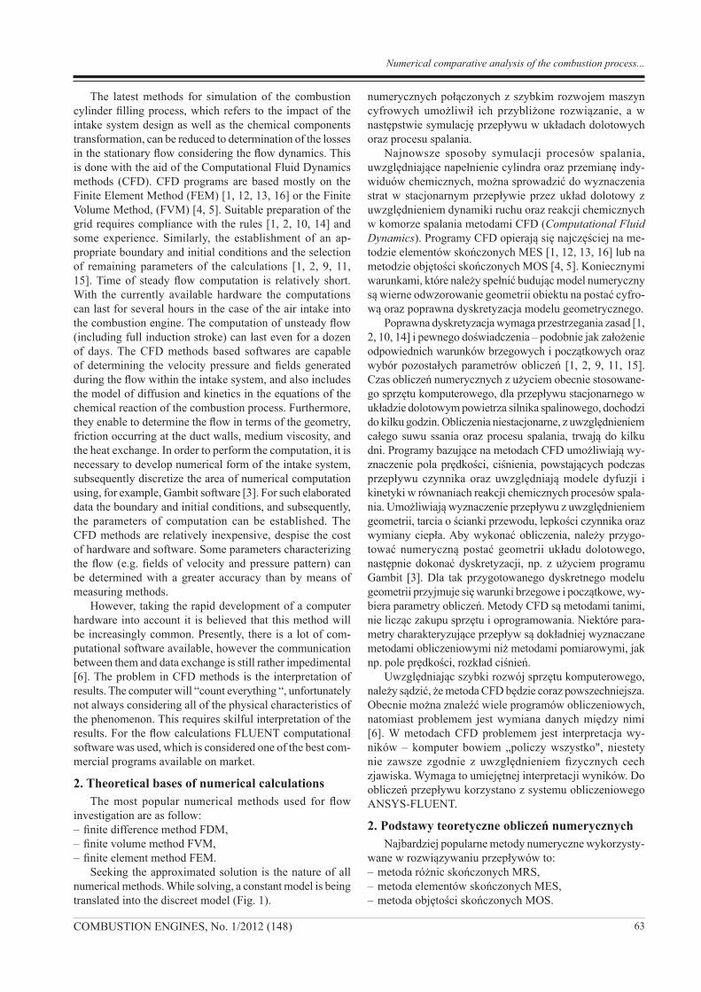
Seeking the approximated solution is the nature of all numerical methods. While solving, a constant model is being translated into the discreet model (Fig. 1).
numerycznych połączonych z szybkim rozwojem maszyn cyfrowych umożliwił ich przybliżone rozwiązanie, a w następstwie symulację przepływu w układach dolotowych oraz procesu spalania.
Najnowsze sposoby symulacji procesów spalania, uwzględniające napełnienie cylindra oraz przemianę indy-widuów chemicznych, można sprowadzić do wyznaczenia strat w stacjonarnym przepływie przez układ dolotowy z uwzględnieniem dynamiki ruchu oraz reakcji chemicznych w komorze spalania metodami CFD (Computational Fluid Dynamics). Programy CFD opierają się najczęściej na me-todzie elementów skończonych MES [1, 12, 13, 16] lub na metodzie objętości skończonych MOS [4, 5]. Koniecznymi warunkami, które należy spełnić budując model numeryczny są wierne odwzorowanie geometrii obiektu na postać cyfro-wą oraz poprawna dyskretyzacja modelu geometrycznego.
Poprawna dyskretyzacja wymaga przestrzegania zasad [1, 2, 10, 14] i pewnego doświadczenia – podobnie jak założenie odpowiednich warunków brzegowych i początkowych oraz wybór pozostałych parametrów obliczeń [1, 2, 9, 11, 15]. Czas obliczeń numerycznych z użyciem obecnie stosowane-go sprzętu komputerowego, dla przepływu stacjonarnego w układzie dolotowym powietrza silnika spalinowego, dochodzi do kilku godzin. Obliczenia niestacjonarne, z uwzględnieniem całego suwu ssania oraz procesu spalania, trwają do kilku dni. Programy bazujące na metodach CFD umożliwiają wy-znaczenie pola prędkości, ciśnienia, powstających podczas przepływu czynnika oraz uwzględniają modele dyfuzji i kinetyki w równaniach reakcji chemicznych procesów spala-nia. Umożliwiają wyznaczenie przepływu z uwzględnieniem geometrii, tarcia o ścianki przewodu, lepkości czynnika oraz wymiany ciepła. Aby wykonać obliczenia, należy przygo-tować numeryczną postać geometrii układu dolotowego, następnie dokonać dyskretyzacji, np. z użyciem programu Gambit [3]. Dla tak przygotowanego dyskretnego modelu geometrii przyjmuje się warunki brzegowe i początkowe, wy-biera parametry obliczeń. Metody CFD są metodami tanimi, nie licząc zakupu sprzętu i oprogramowania. Niektóre para-metry charakteryzujące przepływ są dokładniej wyznaczane metodami obliczeniowymi niż metodami pomiarowymi, jak np. pole prędkości, rozkład ciśnień.
Uwzględniając szybki rozwój sprzętu komputerowego, należy sądzić, że metoda CFD będzie coraz powszechniejsza. Obecnie można znaleźć wiele programów obliczeniowych, natomiast problemem jest wymiana danych między nimi [6]. W metodach CFD problemem jest interpretacja wy-ników – komputer bowiem „policzy wszystko", niestety nie zawsze zgodnie z uwzględnieniem fizycznych cech zjawiska. Wymaga to umiejętnej interpretacji wyników. Do obliczeń przepływu korzystano z systemu obliczeniowego ANSYS-FLUENT.
2. Podstawy teoretyczne obliczeń numerycznychNajbardziej popularne metody numeryczne wykorzysty-
wane w rozwiązywaniu przepływów to:– metoda różnic skończonych MRS,– metoda elementów skończonych MES,– metoda objętości skończonych MOS.
Numerical comparative analysis of the combustion process...
64 COMBUSTION ENGINES, No. 1/2012 (148)
The FLUENT software is based on a Finite Volume Method (FVM), therefore this method is applied for flow calcula-tions in this work. FVM consists in the direct discretization (in the physical space) of equations which are expressing fundamentals of fluid mechanics these equations can be bequeathed as one equation of transport in the following form [1]:
(1)
when: ϕ = 1 – equation of continuity, ϕ = vx – equation of momentum conservation for OX, ϕ = h – equation of energy conservation (h-enthalpy), where: t – time, ρ – density of the fluid, V – volume, A – area, Γ – coefficient of diffusion, S – heat source from ϕ.
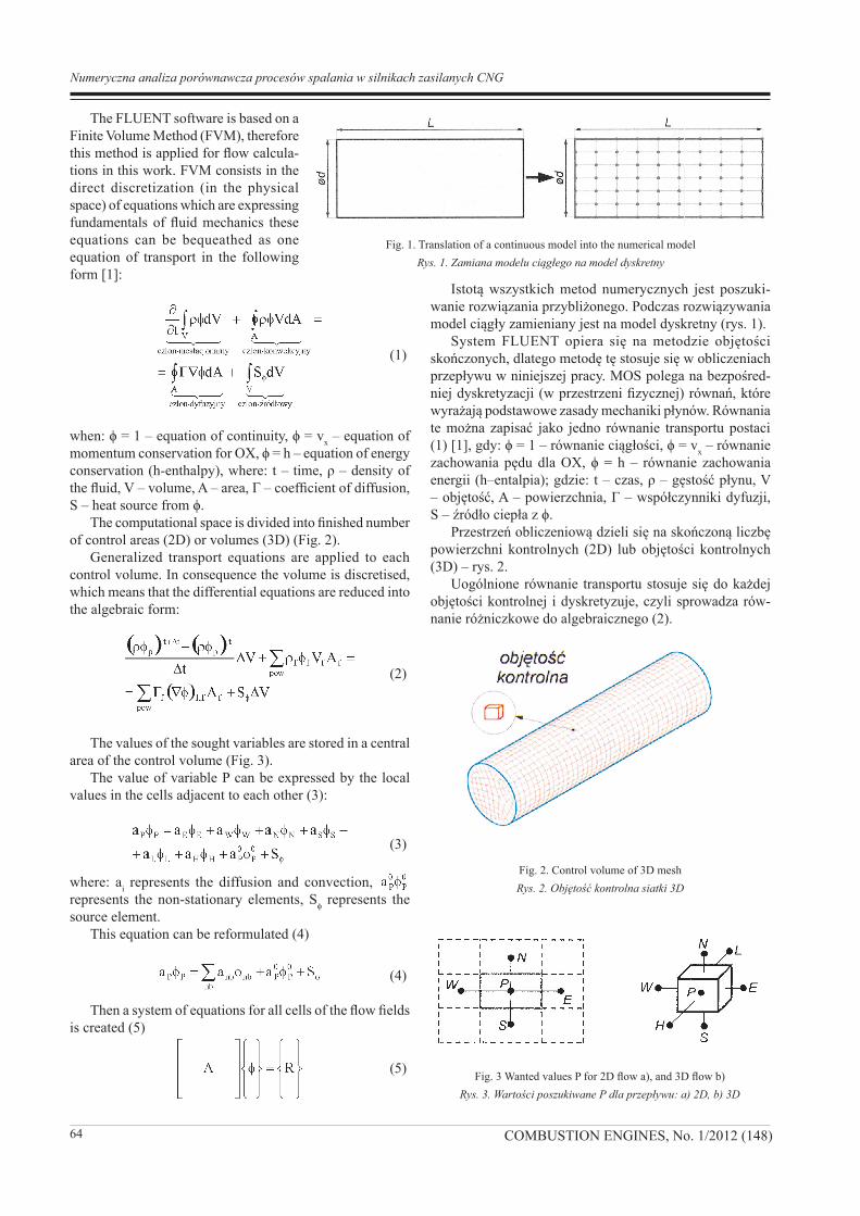
The computational space is divided into finished number of control areas (2D) or volumes (3D) (Fig. 2).
Generalized transport equations are applied to each control volume. In consequence the volume is discretised, which means that the differential equations are reduced into the algebraic form:
(2)
The values of the sought variables are stored in a central area of the control volume (Fig. 3).
The value of variable P can be expressed by the local values in the cells adjacent to each other (3):
(3)
where: ai represents the diffusion and convection, represents the non-stationary elements, Sϕ represents the source element.
This equation can be reformulated (4)
(4)
Then a system of equations for all cells of the flow fields is created (5)
(5)
Istotą wszystkich metod numerycznych jest poszuki-wanie rozwiązania przybliżonego. Podczas rozwiązywania model ciągły zamieniany jest na model dyskretny (rys. 1).
System FLUENT opiera się na metodzie objętości skończonych, dlatego metodę tę stosuje się w obliczeniach przepływu w niniejszej pracy. MOS polega na bezpośred-niej dyskretyzacji (w przestrzeni fizycznej) równań, które wyrażają podstawowe zasady mechaniki płynów. Równania te można zapisać jako jedno równanie transportu postaci (1) [1], gdy: ϕ = 1 – równanie ciągłości, ϕ = vx – równanie zachowania pędu dla OX, ϕ = h – równanie zachowania energii (h–entalpia); gdzie: t – czas, ρ – gęstość płynu, V – objętość, A – powierzchnia, Γ – współczynniki dyfuzji, S – źródło ciepła z ϕ.
Przestrzeń obliczeniową dzieli się na skończoną liczbę powierzchni kontrolnych (2D) lub objętości kontrolnych (3D) – rys. 2.
Uogólnione równanie transportu stosuje się do każdej objętości kontrolnej i dyskretyzuje, czyli sprowadza rów-nanie różniczkowe do algebraicznego (2).
Fig. 1. Translation of a continuous model into the numerical modelRys. 1. Zamiana modelu ciągłego na model dyskretny
Fig. 2. Control volume of 3D meshRys. 2. Objętość kontrolna siatki 3D
Fig. 3 Wanted values P for 2D flow a), and 3D flow b)Rys. 3. Wartości poszukiwane P dla przepływu: a) 2D, b) 3D
Numeryczna analiza porównawcza procesów spalania w silnikach zasilanych CNG
65COMBUSTION ENGINES, No. 1/2012 (148)
This system is solved iteratively in order to satisfy the condition (6):
(6)
Calculations can be carried out in two ways: Coupled or Segregated method. Here and throughout this paper the Segregated method is applied.
3. Numerical investigation of an engine used in heavy-duty vehicle for surface miningA numerical tests of two CNG powered systems was
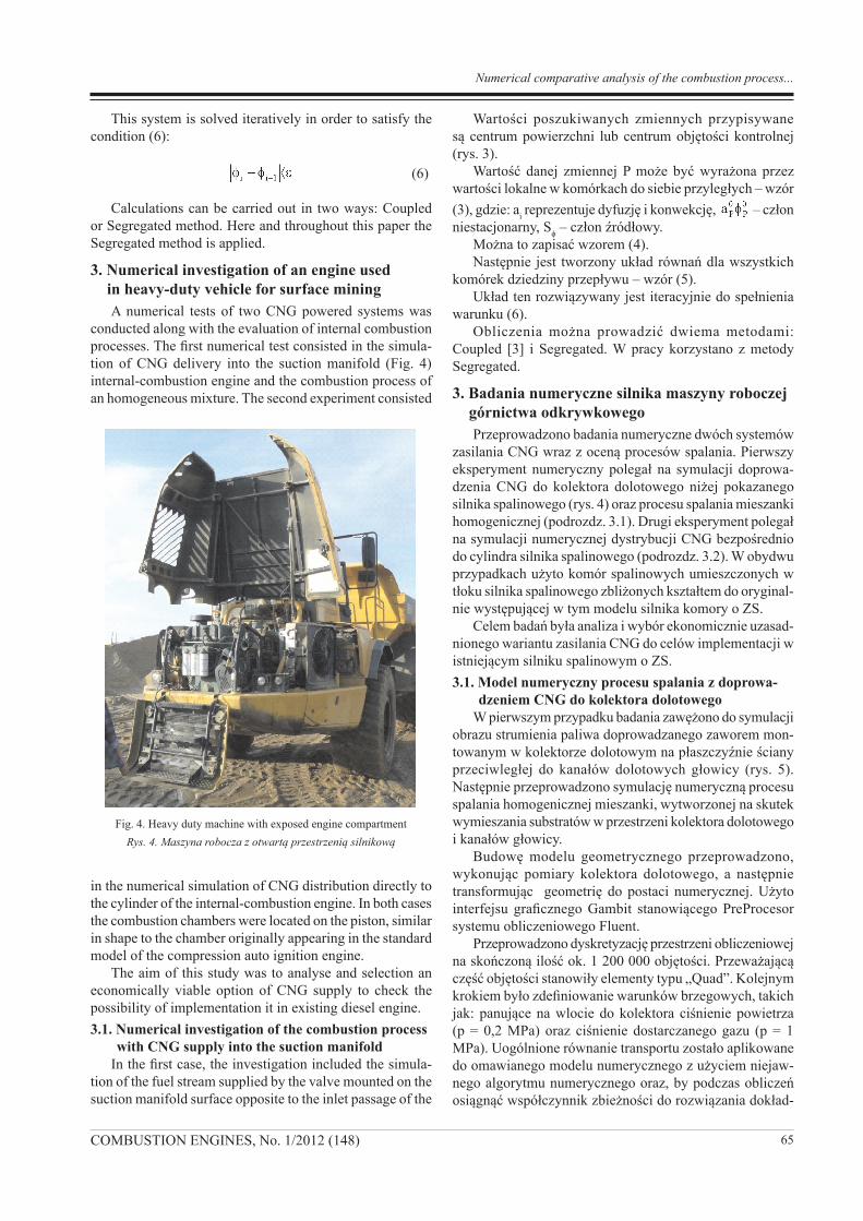
conducted along with the evaluation of internal combustion processes. The first numerical test consisted in the simula-tion of CNG delivery into the suction manifold (Fig. 4) internal-combustion engine and the combustion process of an homogeneous mixture. The second experiment consisted
in the numerical simulation of CNG distribution directly to the cylinder of the internal-combustion engine. In both cases the combustion chambers were located on the piston, similar in shape to the chamber originally appearing in the standard model of the compression auto ignition engine.
The aim of this study was to analyse and selection an economically viable option of CNG supply to check the possibility of implementation it in existing diesel engine.3.1. Numerical investigation of the combustion process
with CNG supply into the suction manifoldIn the first case, the investigation included the simula-
tion of the fuel stream supplied by the valve mounted on the suction manifold surface opposite to the inlet passage of the
Wartości poszukiwanych zmiennych przypisywane są centrum powierzchni lub centrum objętości kontrolnej (rys. 3).
Wartość danej zmiennej P może być wyrażona przez wartości lokalne w komórkach do siebie przyległych – wzór (3), gdzie: ai reprezentuje dyfuzję i konwekcję, – człon niestacjonarny, Sϕ – człon źródłowy.
Można to zapisać wzorem (4).Następnie jest tworzony układ równań dla wszystkich
komórek dziedziny przepływu – wzór (5).Układ ten rozwiązywany jest iteracyjnie do spełnienia
warunku (6).Obliczenia można prowadzić dwiema metodami:
Coupled [3] i Segregated. W pracy korzystano z metody Segregated.
3. Badania numeryczne silnika maszyny roboczej górnictwa odkrywkowegoPrzeprowadzono badania numeryczne dwóch systemów
zasilania CNG wraz z oceną procesów spalania. Pierwszy eksperyment numeryczny polegał na symulacji doprowa-dzenia CNG do kolektora dolotowego niżej pokazanego silnika spalinowego (rys. 4) oraz procesu spalania mieszanki homogenicznej (podrozdz. 3.1). Drugi eksperyment polegał na symulacji numerycznej dystrybucji CNG bezpośrednio do cylindra silnika spalinowego (podrozdz. 3.2). W obydwu przypadkach użyto komór spalinowych umieszczonych w tłoku silnika spalinowego zbliżonych kształtem do oryginal-nie występującej w tym modelu silnika komory o ZS.
Celem badań była analiza i wybór ekonomicznie uzasad-nionego wariantu zasilania CNG do celów implementacji w istniejącym silniku spalinowym o ZS. 3.1. Model numeryczny procesu spalania z doprowa-
dzeniem CNG do kolektora dolotowegoW pierwszym przypadku badania zawężono do symulacji
obrazu strumienia paliwa doprowadzanego zaworem mon-towanym w kolektorze dolotowym na płaszczyźnie ściany przeciwległej do kanałów dolotowych głowicy (rys. 5). Następnie przeprowadzono symulację numeryczną procesu spalania homogenicznej mieszanki, wytworzonej na skutek wymieszania substratów w przestrzeni kolektora dolotowego i kanałów głowicy.
Budowę modelu geometrycznego przeprowadzono, wykonując pomiary kolektora dolotowego, a następnie transformując geometrię do postaci numerycznej. Użyto interfejsu graficznego Gambit stanowiącego PreProcesor systemu obliczeniowego Fluent.
Przeprowadzono dyskretyzację przestrzeni obliczeniowej na skończoną ilość ok. 1 200 000 objętości. Przeważającą część objętości stanowiły elementy typu „Quad”. Kolejnym krokiem było zdefiniowanie warunków brzegowych, takich jak: panujące na wlocie do kolektora ciśnienie powietrza (p = 0,2 MPa) oraz ciśnienie dostarczanego gazu (p = 1 MPa). Uogólnione równanie transportu zostało aplikowane do omawianego modelu numerycznego z użyciem niejaw-nego algorytmu numerycznego oraz, by podczas obliczeń osiągnąć współczynnik zbieżności do rozwiązania dokład-
Fig. 4. Heavy duty machine with exposed engine compartmentRys. 4. Maszyna robocza z otwartą przestrzenią silnikową
Numerical comparative analysis of the combustion process...
66 COMBUSTION ENGINES, No. 1/2012 (148)
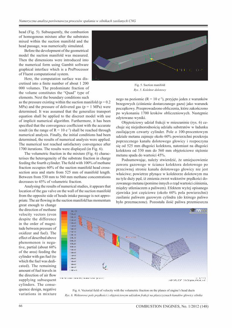
head (Fig. 5). Subsequently, the combustion of homogenous mixture after the substrates mixed within the suction manifold and the head passage, was numerically simulated.
Before the development of the geometrical model the suction manifold was measured. Then the dimensions were introduced into the numerical form using Gambit software graphical interface which is a PreProcessor of Fluent computational system.
Here, the computation surface was dis-cretised into a finite number of about 1 200 000 volumes. The predominate fraction of the volume constitutes the “Quad” type of elements. Next the boundary conditions such as the pressure existing within the suction manifold (p = 0.2 MPa) and the pressure of delivered gas (p = 1 MPa) were determined. It was assumed that the generalize transport equation shall be applied to the discreet model with use of implicit numerical algorithm. Furthermore, it has been specified that the convergence coefficient with the accurate result (in the range of R = 10 e–5) shall be reached through numerical analysis. Finally, the initial conditions had been determined, the results of numerical analysis were applied. The numerical test reached satisfactory convergence after 1700 iterations. The results were displayed (in Fig. 6).
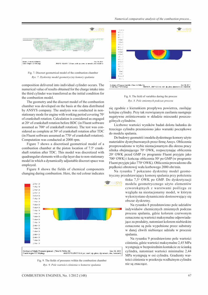
The volumetric fraction in the mixture (Fig. 6) charac-terises the heterogeneity of the substrate fraction in charge feeding the fourth cylinder. The field with 100% of methane fraction occupies 60% of the suction manifold head cross-section area and starts from 525 mm of manifold length. Between from 530 mm to 560 mm methane concentrations decreases to 45% of volumetric fraction.
Analysing the results of numerical studies, it appears that location of the gas valve on the wall of the suction manifold from the opposite side of heads intake passage is not appro-priate. The air flowing in the suction manifold has momentum great enough to change the direction of methane velocity vectors (even despite the difference in the order of magni-tude between pressure of oxidizer and fuel). The effect of described above phenomenon is nega-tive, partial (about 60% of the area) feeding the cylinder with gas fuel (to which the fuel was dedi-cated). The remaining amount of fuel travels in the direction of air flow supplying subsequent cylinders. The conse-quence design, negative variations in mixture
nego na poziomie (R = 10 e–5), przyjęto jeden z warunków brzegowych (ciśnienie dostarczanego gazu) jako warunek początkowy. Przeprowadzono obliczenia, które zakończono po wykonaniu 1700 kroków obliczeniowych. Następnie edytowano wyniki.
Objętościowy udział frakcji w mieszaninie (rys. 6) ce-chuje się niejednorodnością udziału substratów w ładunku zasilającym czwarty cylinder. Pole o 100-procentowym udziale metanu zajmuje około 60% powierzchni przekroju poprzecznego kanału dolotowego głowicy i rozpoczyna się od 525 mm długości kolektora, natomiast na długości kolektora od 530 mm do 560 mm objętościowe stężenie metanu spada do wartości 45%.
Podsumowując, należy stwierdzić, że umiejscowienie zaworu gazowego w ściance kolektora dolotowego po przeciwnej stronie kanału dolotowego głowicy nie jest właściwe; powietrze płynące w kolektorze dolotowym ma na tyle duży pęd, iż zmienia zwrot wektorów prędkości do-zowanego metanu (pomimo innych o rząd wartości ciśnienia, między utleniaczem a paliwem). Efektem wyżej opisanego zjawiska jest częściowe (około 60% pola powierzchni) zasilanie paliwem gazowym cylindra (do którego paliwo było przeznaczone). Pozostała ilość paliwa przemieszcza
Fig. 5. Suction manifoldRys. 5. Kolektor dolotowy
Fig. 6. Vectorial field of velocity with the volumetric fraction on the planes of engine’s head ductsRys. 6. Wektorowe pole prędkości z objętościowym udziałem frakcji na płaszczyznach kanałów głowicy silnika
Numeryczna analiza porównawcza procesów spalania w silnikach zasilanych CNG
67COMBUSTION ENGINES, No. 1/2012 (148)
composition delivered into individual cylinder occurs. The numerical value of results obtained for the charge intake into the third cylinder was transferred as the initial condition for the combustion model.
The geometry and the discreet model of the combustion chamber was developed on the basis at the data distributed by ANSYS company. The analysis was conducted in non-stationary mode for engine with working period covering 70o of crankshaft rotation. Calculation is considered as engaged at 20o of crankshaft rotation before BDC (in Fluent software assumed as 700o of crankshaft rotation). The test was con-sidered as complete at 50o of crankshaft rotation after TDC (in Fluent software assumed as 770o of crankshaft rotation). Computation was conducted at 2000 rpm.
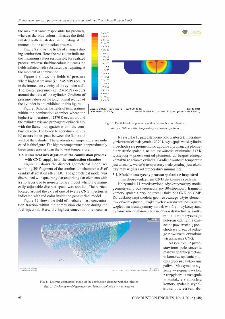
Figure 7 shows a discretised geometrical model of a combustion chamber at the piston location of 7.5o crank-shaft rotation after TDC. This model was discretized with quadrangular elements with a slip layer due to non-stationary model in which a dynamically adjustable discreet space was employed.
Figure 8 shows the fields of chemical components changing during combustion. Here, the red colour indicates
się zgodnie z kierunkiem przepływu powietrza, zasilając kolejne cylindry. Przy tak rozwiązanym zasilaniu następuje negatywne zróżnicowanie w składzie mieszanki poszcze-gólnych cylindrów.
Liczbowe wartości wyników badań dolotu ładunku do trzeciego cylindra przeniesiono jako warunki początkowe do modelu spalania.
Do budowy geometrii i modelu dyskretnego komory użyto materiałów dystrybuowanych przez firmę Ansys. Obliczenia przeprowadzono w trybie niestacjonarnym dla okresu pracy silnika obejmującego 70o OWK, rozpoczynając obliczenia 20o OWK przed GMP (w programie Fluent przyjęte jako 700o OWK) i kończąc obliczenia 50o po GMP (w programie Fluent przyjęte jako 770o OWK). Obliczenia prowadzono dla prędkości obrotowej wału korbowego 2000 obr/min.
Na rysunku 7 pokazano dyskretny model geome-tryczny przedstawiający komorę spalania przy położeniu
tłoka 7,5o OWK po GMP. Do dyskretyzacji modelu geometrycznego użyto elementów czworokątnych z warstwami poślizgu ze względu na niestacjonarny model, w którym wykorzystano dynamicznie dostosowujący się obszar dyskretny.
Na rysunku 8 przedstawiono pole udziałów indywiduów chemicznych zmiennych podczas procesu spalania, gdzie kolorem czerwonym oznaczone są wartości maksymalne odpowiada-jące za produkty, natomiast kolorem niebieskim oznaczone są pola wypełnione przez substraty w danej chwili niebiorące udziału w procesie spalania.
Na rysunku 9 przedstawiono pole wartości ciśnienia, gdzie wartości maksymalne 2,45 MPa występują w bezpośrednim kontakcie ze ścianką cylindra, natomiast wartości minimalne 2,44 MPa występują w osi cylindra. Gradienty war-tości ciśnienia w przekroju wzdłużnym cylindra nie są znaczące.
Fig. 7. Discreet geometrical model of the combustion chamberRys. 7. Dyskretny model geometryczny komory spalania
Fig. 8. The field of variables during the processRys. 8. Pole zmiennych podczas procesu
Fig. 9. The fields of pressures within the combustion chamberRys. 9. Pole wartości ciśnienia w komorze spalania
Numerical comparative analysis of the combustion process...
68 COMBUSTION ENGINES, No. 1/2012 (148)
the maximal value responsible for products, whereas the blue colour indicates the fields inflated with substrates participating at the moment in the combustion process.
Figure 8 shows the fields of changes dur-ing combustion. Here, the red colour indicates the maximum values responsible for realized process, whereas the blue colour indicates the fields inflated with substrates participating at the moment at combustion.
Figure 9 shows the fields of pressure where highest pressure (i.e. 2.45 MPa) occurs in the immediate vicinity of the cylinder wall. The lowest pressure (i.e. 2.4 MPa) occurs around the axis of the cylinder. Gradient of pressure values on the longitudinal section of the cylinder is not exhibited in this figure.
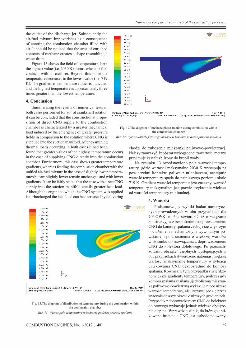
Figure 10 shows the fields of temperatures within the combustion chamber where the highest temperature of 2370 K occurs around the cylinder axis and propagates cylindrically with the flame propagation within the com-bustion zone. The lowest temperature (i.e. 737 K) occurs in the space between the flame and wall of the cylinder. The gradients of temperature are indi-cated in this figure. The highest temperature is approximately three times greater than the lowest temperature. 3.2. Numerical investigation of the combustion process
with CNG supply into the combustion chamberFigure 11 shows the discreet geometrical model re-
sembling 30o fragment of the combustion chamber at 5o of crankshaft rotation after TDC. The geometrical model was discretized with quadrangular and triangular elements with a slip layer due to non-stationary model where a dynami-cally adjustable discreet space was applied. The surface located around the axis of one of twelve CNG injectors is indicated with red color inside the geometrical model.
Figure 12 shows the field of methane mass concentra-tion fraction within the combustion chamber during the fuel injection. Here, the highest concentrations occur at
Na rysunku 10 przedstawiono pole wartości temperatury, gdzie wartości maksymalne 2370 K występują w osi cylindra i rozchodzą się promieniowo zgodnie z propagacją płomie-nia w strefie spalania, natomiast wartości minimalne 737 K występują w przestrzeni od płomienia do bezpośredniego kontaktu ze ścianką cylindra. Gradient wartości temperatur jest znaczny, wartość temperatury maksymalnej jest około trzy razy większa od temperatury minimalnej.3.2. Model numeryczny procesu spalania z bezpośred-
nim doprowadzeniem CNG do komory spalaniaNa rysunku 11 przedstawiono zdyskretyzowany model
geometryczny odzwierciedlający 30-stopniowy fragment komory spalania przy położeniu tłoka 5o OWK po GMP. Do dyskretyzacji modelu geometrycznego użyto elemen-tów czworokątnych i trójkątnych z warstwami poślizgu ze względu na niestacjonarny model, w którym wykorzystano dynamicznie dostosowujący się obszar dyskretny. W środku
modelu numerycznego kolorem czarnym zazna-czono powierzchnię prze-chodzącą przez oś jedne-go z dwunastu otworków wtryskiwacza CNG.
Na rysunku 12 przed-stawiono pole stężenia masowego frakcji metanu w komorze spalania pod-czas procesu dawkowania paliwa. Maksymalne stę-żenie występuje u wylotu z rozpylacza, a następnie w kontakcie z atmosferą komory spalania wypeł-nioną powietrzem do-
Fig. 10. The fields of temperatures within the combustion chamberRys. 10. Pole wartości temperatury w komorze spalania
Fig. 11. Discreet geometrical model of the combustion chamber with the injectorRys. 11. Dyskretny model geometryczny komory spalania z wtryskiwaczem
Numeryczna analiza porównawcza procesów spalania w silnikach zasilanych CNG
69COMBUSTION ENGINES, No. 1/2012 (148)
the outlet of the discharge jet. Subsequently the air-fuel mixture impoverishes as a consequence of entering the combustion chamber filled with air. It should be noticed that the area of enriched contents of methane creates a shape resembling a water drop.
Figure 13 shows the field of temperature, here the highest value (i.e. 2030 K) occurs when the fuel contacts with an oxidiser. Beyond this point the temperature decreases to the lowest value (i.e. 719 K). The gradient of temperature values is indicated and the highest temperature is approximately three times greater than the lowest temperature.
4. ConclusionSummarizing the results of numerical tests in
both cases performed for 70° of crankshaft rotation it can be concluded that the constructional propo-sition of direct CNG supply to the combustion chamber is characterized by a greater mechanical load induced by the emergence of greater pressure fields in comparison to the solution where CNG is supplied into the suction manifold. After examining thermal loads occurring in both cases it had been found that greater values of the highest temperature occurs in the case of supplying CNG directly into the combustion chamber. Furthermore, this case shows greater temperature gradients, whereas feeding the combustion chamber with the unified air-fuel mixture in the case of slightly lower tempera-tures but are slightly lower remain unchanged and with lower gradients. It can be fairly stated that the case with direct CNG supply into the suction manifold entails greater heat load. Although the engine to which the CNG system was applied is turbocharged the heat load can be decreased by delivering
chodzi do zubożenia mieszanki paliwowo-powietrznej. Należy zauważyć, iż obszar wzbogaconej zawartości metanu przyjmuje kształt zbliżony do kropli wody.
Na rysunku 13 przedstawiono pole wartości tempe-ratury, gdzie wartości maksymalne 2030 K występują na powierzchni kontaktu paliwa z utleniaczem, następnie wartość temperatury spada do najniższego poziomu około 719 K. Gradient wartości temperatur jest znaczny, wartość temperatury maksymalnej jest prawie trzykrotnie większa od wartości temperatury minimalnej.
4. WnioskiPodsumowując wyniki badań numerycz-
nych prowadzonych w obu przypadkach dla 70o OWK, można stwierdzić, iż rozwiązanie konstrukcyjne z bezpośrednim doprowadzeniem CNG do komory spalania cechuje się większym obciążeniem mechanicznym wywołanym po-wstaniem pola ciśnienia o większej wartości w stosunku do rozwiązania z doprowadzeniem CNG do kolektora dolotowego. Po przeanali-zowaniu obciążeń cieplnych występujących w obu przypadkach stwierdzono natomiast większe wartości maksymalne temperatury w sytuacji dawkowania CNG bezpośrednio do komory spalania. Również w tym przypadku stwierdzo-no większe gradienty temperatury, podczas gdy komora spalania zasilana ujednoliconą mieszan-ką paliwowo-powietrzną wykazuje nieco niższe wartości temperatury, ale utrzymujące się przez znacznie dłuższy okres i o niższych gradientach. Przypadek z doprowadzeniem CNG do kolektora dolotowego wykazuje jednak większe obciąże-nia cieplne. Wprawdzie silnik, do którego apli-kowano instalacje CNG jest turbodoładowany,
Fig. 12.The diagram of methane phase fraction during combustion within the combustion chamber
Rys. 12. Wykres udziału fazowego metanu w komorze podczas procesu spalania
Fig. 13.The diagram of distribution of temperature during the combustion within the combustion chamber
Rys. 13. Wykres pola temperatury w komorze podczas procesu spalania
Numerical comparative analysis of the combustion process...
70 COMBUSTION ENGINES, No. 1/2012 (148)
a na drodze zwiększania ilości doprowadzanego powietrza można zmniejszyć obciążenia cieplne, jednak pod warun-kiem odpowiedniego dostosowania przekrycia zaworów.
Przy obecnym stanie wiedzy dostarczonej przez badania numeryczne obu sposobów zasilania CNG, ekonomicznie uzasadnione wydaje się rozwiązanie z pośrednim dopro-wadzeniem CNG, jednak do podjęcia ostatecznej decyzji konieczna jest symulacja porównawcza wtrysku oleju napę-dowego, do zasilania którym dany silnik był konstrukcyjnie przewidziany.
Badania numeryczne z użyciem metod CFD do okre-ślania możliwości zastosowania paliw alternatywnych w istniejących lub konstruowanych silnikach spalinowych mają coraz większe zastosowanie ze względu na niskie koszty oraz coraz większą dokładność.
greater amount of air. This however, can be only done with the appropriated of valve covering adjustment.
On the basis of the results provided by the numerical investigation of both CNG supply cases, it is clear that the economically viable solution is the indirect CNG supply. However, it requires further comparative simulation of the diesel oil injection to which the engine was constructed.
Numerical investigation with the use of CFD method for determination of the alternative fuels applicability in existing engines or engines under construction gains greater popularity due to low costs and they constantly increasing accuracy.
Bibliography/Literatura[1] Ansys.inc., ANSYS Fluent 6.3 Theory Guide 2011.[2] Atkins W.S.: Consultants and Members of the NSC, Best
Practice Guidelines for Marine Aplications of Computational Fluid Dynamics, Sirehna, HSVA, FLOWTECH, VTT, Impe-rial College of Science & Technology, Germanischer Lloyd, Astilleros Espanoles, http://pronet.wsatkins.co.uk/marnet/
[3] Fluent Inc., Fluent 6.1 User`s Guide, 2011.[4] Gryboś R.: Podstawy mechaniki płynów, Wydawnictwo Na-
ukowe PWN, Warszawa 1998.[5] Johnson R.: Fluid Dynamice, CRC Press LLC, Floryda
1998.[6] Khodorovsky A.: Experience in Using Various CAD Systems
for Hull Lines Design. Problems of CAD System Integration into Current Design Technology, 14th International Confe-rence on Hydrodynamics in Ship Design HYDRONAV 2001, Szczecin – Miedzyzdroje, September, 27–29, 2001.
Krzysztof Miksiewicz, DEng. – doctor in the Faculty of Mechanics and Machine Construction Wrocław University of Technology.dr inż. Krzysztof Miksiewicz – adiunkt w Instytucie Konstrukcji i Eksploatacji Maszyn Wydziału Me-chanicznego Politechniki Wrocławskiej.e-mail: [email protected]
Paper reviewed/Artykuł recenzowany
Marcin Tkaczyk, DEng. – doctor in the Faculty of Mechanics and Machine Construction Wrocław University of Technology.dr inż. Marcin Tkaczyk – adiunkt w Instytucie Konstrukcji i Eksploatacji Maszyn Wydziału Me-chanicznego Politechniki Wrocławskiej.e-mail: [email protected]
Ryszard Michałowski Eng. – Head of the Wał-brzych Gasworks, PGNiG Group.mgr inż. Ryszard Michałowski – Dyrektor Gazowni Wałbrzyskiej, PGNiG SA, Dolnośląski Oddział Obrotu Gazem we Wrocławiu.e-mail: [email protected]
[7] Mysłowski J.: Doładowanie bezsprężarkowe silników z za-płonem samoczynnym. WNT, Warszawa 1995.
[8] Mysłowski J.: Doładowanie silników. WKiŁ, Warszawa 2002.
[9] Oertel Jr. H., Laurien E.: Numerische Stromungsmechanik, Springer-Verlag, Berlin 1995.
[10] Olsen N.: Computational Fluid Dynamics in Hydraulic and Sedimentation Engineering, The Norwegian University of Science and Technology, Trondheim 1999.
[11] Peyreat R., Taylor T.: Computational Methods for Fluid Flow, Springer-Verlag, New York 1983.
[12] Rusiński E., Czmochowski J., Smolnicki T.: Zaawansowana metoda elementów skończonych w konstrukcjach nośnych, Oficyna Wydawnicza Politechniki Wrocławskiej, Wrocław 2000.
[13] Rusiński E.: Zasady projektowania konstrukcji nośnych po-jazdów samochodowych, Oficyna Wydawnicza Politechniki Wrocławskiej, Wrocław 2002.
[14] Thompson J., Warsi Z., Mastin C.: Numerical Grid Generation Fundations and Applications, Elsavier Science Publishing Co., Inc., New York 1985.
[15] Wilcox D.: Turbulence Modeling for CFD, KNI, Inc., Anaheim 2002.
[16] Zienkiewicz O.: Metoda elementów skończonych, Arkady, Warszawa 1972.
Numeryczna analiza porównawcza procesów spalania w silnikach zasilanych CNG