
Novel low power microwave plasma sources at …pe.org.pl/articles/2012/8/12.pdf · 40 PRZEGLĄD...
4
PRZEGLĄD ELEKTROTECHNICZNY (Electrical Review), ISSN 0033-2097, R. 88 NR 8/2012 39 Dariusz CZYLKOWSKI 1 , Mariusz JASIŃSKI 1 , Jerzy MIZERACZYK 1,2 The Szewalski Institute of Fluid Flow Machinery, Gdańsk (1), Gdynia Maritime University (2) Novel low power microwave plasma sources at atmospheric pressure Abstract. The aim of this paper is to present the results of our experimental investigations concerning novel low power microwave plasma sources. Such devices are of high interest from industry point of view, namely for plastic or metal surface treatment. Proposed by us plasma sources are small, simple and low cost. Plasma generated by them is of regular shape. They can be operated at atmospheric pressure, at standard frequency of 2.45 GHz and microwave power lower than 500 W. Streszczenie. Celem pracy jest zaprezentowanie opracowanych przez nas nowych mikrofalowych źródeł plazmy małej mocy. Takie urządzenia cieszą się zainteresowaniem przemysłu w celu zastosowań w obróbce plastikowych i metalowych powierzchni. Zaproponowane przez nas źródła plazmy małej mocy są małe, proste I tanie. Pracują pod ciśnieniem atmosferycznym I standardowej częstotliwości 2,45 GHz. (Nowe małej mocy mikrofalowe źródło plazmy przy ciśnieniu atmosferycznym) Keywords: atmospheric pressure discharge, microwave plasma sources, surface treatment. Słowa kluczowe: wyładowanie pod ciśnieniem atmosferycznym, mikrofalowe źródła plazmy, obróbka powierzchni. Introduction To meet industry expectations of having small and low cost source of plasma for surface treatment we started an experimental investigations concerning this problem. One of the promising plasma application is the removing of unwanted photoresist in the semiconductor and photo- electronic industries [1]. Produced plasma is used for the removal of pollutants in order to improve surface conditions and to enhance the adhesion strength of substrate before photoresist coat. Microwave plasma surface treatment also find applications in cars production, aviation industry, textiles and in biomedical engineering [2-5]. Except above- named properties generated plasma should be regular in shape. Currently, devices provided plasmas in the form of flame [6] or column [7] are well known. In this paper we present results of our work and we propose a few novel low power microwave plasma sources. These are: waveguide slit plasma generator, multijet microwave plasma generator and microwave plasma sheet generator. All of them were designed, built and testes in our Centre for Plasma and Laser Engineering of our Institute. They are operated at atmospheric pressure, at standard frequency of 2.45 GHz and microwave power not exceeding 500 W. Experimental setup The diagram of the setup used for experimental investigations of novel microwave plasma sources is shown in the figure 1. Its essential components are: microwave generator, isolator, directional coupler with power meters, three stub tuner, microwave plasma generator, gas flow control and measurement system and movable plunger. Fig.1. The diagram of the setup for experimental investigations of novel microwave plasma sources The microwave generator is a source of electromagnetic radiation at frequency of 2.45 GHz and maximal microwave power of 2 kW. Calibrated directional couplers are used to sample the incident and reflected microwave power at the plasma generator input. The diverted fractions of power are measured with power meters. The three stub tuner and movable plunger are impedance matching devices. Matching the impedance of a plasma generator to the impedance of a transmission line is in some cases desirable for better microwave power transfer. Generally, they can exist in the experimental setup but not have to. The microwave plasma generator can be supplied by coaxial cable or stripline structures in the case of lower microwave powers. When operating with higher microwave powers the plasma generator should be fed through waveguide. In this paper we present plasma generators based either on stripline structure or rectangular waveguide. For initiate the discharge a high voltage spark source is used. In the figure 2 the diagram of the setup for industry applications is shown. Fig.2. The diagram of the setup for industry applications Comparing with setup presented in the figure 1 there is lack of microwave power measurement system and impedance matching devices. Also the microwave generator is of different structure. Because of demand not too high microwave power to supply our novel plasma sources the microwave generator can incorporates the magnetron typical for microwave ovens assuring power up to 1000 W. It should be also noted that such device does not require the water cooling. It can also work without isolator. All experimental tests were performed with argon and neon at a flow rate up to 25 l/min and microwave power up to 500 W. Waveguide slit plasma generator The new waveguide slit plasma generator is based on the WR 430 standard rectangular waveguide. Its sketch is presented in the figure 3. It has the form of the wedge waveguide tipped with a slit of dimensions 1×54.6 mm. From microwave power input side the generator is terminated with a teflon plate which prevent flowing of the gas to the waveguide circuit. Generated in the waveguide slit plasma due to the gas flow leaves the waveguide region. Protruded plasma gives the possibility of contact
Transcript of Novel low power microwave plasma sources at …pe.org.pl/articles/2012/8/12.pdf · 40 PRZEGLĄD...
PRZEGLĄD ELEKTROTECHNICZNY (Electrical Review), ISSN 0033-2097, R. 88 NR 8/2012 39
Dariusz CZYLKOWSKI1, Mariusz JASIŃSKI1, Jerzy MIZERACZYK1,2
The Szewalski Institute of Fluid Flow Machinery, Gdańsk (1), Gdynia Maritime University (2)
Novel low power microwave plasma sources at atmospheric pressure
Abstract. The aim of this paper is to present the results of our experimental investigations concerning novel low power microwave plasma sources. Such devices are of high interest from industry point of view, namely for plastic or metal surface treatment. Proposed by us plasma sources are small, simple and low cost. Plasma generated by them is of regular shape. They can be operated at atmospheric pressure, at standard frequency of 2.45 GHz and microwave power lower than 500 W. Streszczenie. Celem pracy jest zaprezentowanie opracowanych przez nas nowych mikrofalowych źródeł plazmy małej mocy. Takie urządzenia cieszą się zainteresowaniem przemysłu w celu zastosowań w obróbce plastikowych i metalowych powierzchni. Zaproponowane przez nas źródła plazmy małej mocy są małe, proste I tanie. Pracują pod ciśnieniem atmosferycznym I standardowej częstotliwości 2,45 GHz. (Nowe małej mocy mikrofalowe źródło plazmy przy ciśnieniu atmosferycznym) Keywords: atmospheric pressure discharge, microwave plasma sources, surface treatment. Słowa kluczowe: wyładowanie pod ciśnieniem atmosferycznym, mikrofalowe źródła plazmy, obróbka powierzchni. Introduction To meet industry expectations of having small and low cost source of plasma for surface treatment we started an experimental investigations concerning this problem. One of the promising plasma application is the removing of unwanted photoresist in the semiconductor and photo-electronic industries [1]. Produced plasma is used for the removal of pollutants in order to improve surface conditions and to enhance the adhesion strength of substrate before photoresist coat. Microwave plasma surface treatment also find applications in cars production, aviation industry, textiles and in biomedical engineering [2-5]. Except above-named properties generated plasma should be regular in shape. Currently, devices provided plasmas in the form of flame [6] or column [7] are well known. In this paper we present results of our work and we propose a few novel low power microwave plasma sources. These are: waveguide slit plasma generator, multijet microwave plasma generator and microwave plasma sheet generator. All of them were designed, built and testes in our Centre for Plasma and Laser Engineering of our Institute. They are operated at atmospheric pressure, at standard frequency of 2.45 GHz and microwave power not exceeding 500 W. Experimental setup The diagram of the setup used for experimental investigations of novel microwave plasma sources is shown in the figure 1. Its essential components are: microwave generator, isolator, directional coupler with power meters, three stub tuner, microwave plasma generator, gas flow control and measurement system and movable plunger.
Fig.1. The diagram of the setup for experimental investigations of novel microwave plasma sources
The microwave generator is a source of electromagnetic radiation at frequency of 2.45 GHz and maximal microwave power of 2 kW. Calibrated directional couplers are used to sample the incident and reflected microwave power at the plasma generator input. The diverted fractions of power are
measured with power meters. The three stub tuner and movable plunger are impedance matching devices. Matching the impedance of a plasma generator to the impedance of a transmission line is in some cases desirable for better microwave power transfer. Generally, they can exist in the experimental setup but not have to. The microwave plasma generator can be supplied by coaxial cable or stripline structures in the case of lower microwave powers. When operating with higher microwave powers the plasma generator should be fed through waveguide. In this paper we present plasma generators based either on stripline structure or rectangular waveguide. For initiate the discharge a high voltage spark source is used. In the figure 2 the diagram of the setup for industry applications is shown.
Fig.2. The diagram of the setup for industry applications Comparing with setup presented in the figure 1 there is lack of microwave power measurement system and impedance matching devices. Also the microwave generator is of different structure. Because of demand not too high microwave power to supply our novel plasma sources the microwave generator can incorporates the magnetron typical for microwave ovens assuring power up to 1000 W. It should be also noted that such device does not require the water cooling. It can also work without isolator. All experimental tests were performed with argon and neon at a flow rate up to 25 l/min and microwave power up to 500 W. Waveguide slit plasma generator The new waveguide slit plasma generator is based on the WR 430 standard rectangular waveguide. Its sketch is presented in the figure 3. It has the form of the wedge waveguide tipped with a slit of dimensions 1×54.6 mm. From microwave power input side the generator is terminated with a teflon plate which prevent flowing of the gas to the waveguide circuit. Generated in the waveguide slit plasma due to the gas flow leaves the waveguide region. Protruded plasma gives the possibility of contact
40 PRZEGLĄD ELEKTROTECHNICZNY (Electrical Review), ISSN 0033-2097, R. 88 NR 8/2012
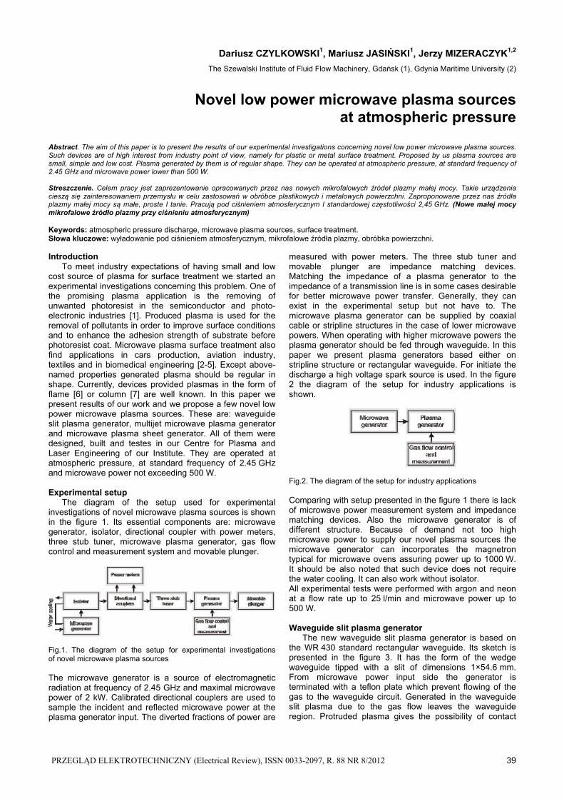
with treatment material. For initiation the discharge the absorbed microwave power PA, as low as 50 W, is required.
Fig.3. The sketch of the waveguide slit plasma generator The photos of the slit argon plasma for different values of absorbed microwave power PA and gas flow rate of Q=25 l/min are presented in the figure 4. As it can be seen depending on the absorbed microwave power PA the
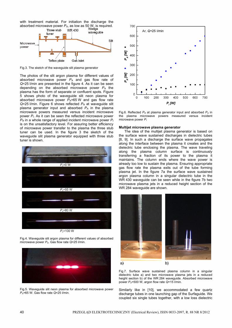
plasma has the form of separate or confluent spots. Figure 5 shows photo of the waveguide slit neon plasma for absorbed microwave power PA=65 W and gas flow rate Q=25 l/min. Figure 6 shows reflected PR at waveguide slit plasma generator input and absorbed PA in the plasma microwave powers measured versus incident microwave power PI. As it can be seen the reflected microwave power PR in a whole range of applied incident microwave power PI is on the unsatisfactory level. For assuring better efficiency of microwave power transfer to the plasma the three stub tuner can be used. In the figure 3 the sketch of the waveguide slit plasma generator equipped with three stub tuner is shown.
Fig.4. Waveguide slit argon plasma for different values of absorbed microwave power PA. Gas flow rate Q=25 l/min.
Fig.5. Waveguide slit neon plasma for absorbed microwave power PA=65 W. Gas flow rate Q=25 l/min.
Fig.6. Reflected PR at plasma generator input and absorbed PA in the plasma microwave powers measured versus incident microwave power PI
Multijet microwave plasma generator The idea of the multijet plasma generator is based on the surface wave sustained discharges in dielectric tubes [8, 9]. In such a discharge the surface wave propagates along the interface between the plasma it creates and the dielectric tube enclosing the plasma. The wave traveling along the plasma column surface is continuously transferring a fraction of its power to the plasma it maintains. The column ends where the wave power is already too low to sustain the plasma. Ensuring appropriate gas flow rate the plasma exits out of the tube forming plasma jet. In the figure 7a the surface wave sustained argon plasma column in a singular dielectric tube in the WR 430 waveguide can be seen while in the figure 7b two microwave plasma jets in a reduced height section of the WR 284 waveguide are shown.
Fig.7. Surface wave sustained plasma column in a singular dielectric tube a) and two microwave plasma jets in a reduced height section b) of the WR 284 waveguide. Absorbed microwave power PA=500 W, argon flow rate Q=15 l/min.
Similarly like in [10], we accommodated a few quartz discharge tubes in one launching gap of the Surfaguide. We coupled six single tubes together, with a low loss dielectric

PRZEGLĄD ELEKTROTECHNICZNY (Electrical Review), ISSN 0033-2097, R. 88 NR 8/2012 41
glue, in a single file. The inner and outer diameters of each tube are 1 and 5 mm, respectively. Such small tube inner diameter prevents plasma filamentation. In the figure 8 the photo of the six microwave plasma jets, for absorbed microwave power PA=500 W, and argon total flow rate Q=15 l/min, can be seen. Changing the gas flow rate and position of the tubes within the waveguide the length of the plasma jets can be changed.
Fig.8. Six microwave plasma jets in a reduced height section of the WR 284 waveguide. Absorbed microwave power PA=500 W, argon flow rate Q=15 l/min. In the figure 9 different possible configuration of six microwave plasma jets on the WR 284 waveguide wide wall can be seen. In the figure 9a perpendicularly to waveguide axis, in the figure 9b parallel to waveguide axis and in the figure 9c not tested during our investigations centrally placed plasma jets in the form of fascile. Figure 10 shows six microwave plasma jets in a reduced height section of the WR 284 waveguide during metal plate treatment. Absorbed microwave power PA=500 W, argon flow rate Q=15 l/min.
Fig.9. Different configuration of six microwave plasma jets on the WR 284 waveguide wide wall: a) perpendicularly to waveguide axis b) parallel to waveguide axis c) centrally in the form of fascile
Fig.10. Six microwave plasma jets in a reduced height section of the WR 284 waveguide during metal plate treatment. Absorbed microwave power PA=500 W, argon flow rate Q=15 l/min. Microwave plasma sheet generator Presented in this section microwave plasma sheet generator was firstly described in [11] and [12]. Its main advantage is a shape of generated plasma, namely sheet shape. It is convenient from surface treatment point of view, thus attractive for industry. The plasma is generated inside a quartz box through which the working gas flows. Because of the gas flow the plasma goes out of a box permitting the processing of the material’s surface (see figure 11).
Fig.11. Plasma sheet, fed through waveguide, during metal plate treatment. Microwave power PI=250 W, argon flow rate Q=25 l/min.
The exemplary dimensions of the generated plasma sheet could be 50 mm of width and 1 mm of thickness for absorbed microwave power PA=200 W and argon flow rate Q=5 l/min. Depending on the microwave power and gas flow rate the gas temperature of the generated plasma varies from 400ºC to 800ºC. Presented here plasma sheet generator can be supplied from a waveguide (see figure 11), from a wedge waveguide (figure 13) or a stripline (figure 12). Figure 14 presents the reflected PR at plasma generator input and absorbed PA in the plasma microwave powers measured versus incident microwave power PI in the case of plasma sheet generator supplied from a waveguide wedge.

42 PRZEGLĄD ELEKTROTECHNICZNY (Electrical Review), ISSN 0033-2097, R. 88 NR 8/2012
Fig.12. Stripline based device for generation of the microwave plasma sheet. Microwave power PI=300 W, argon flow rate Q=5 l/min.
Fig.13. Plasma sheet generator supplied from a waveguide wedge. Microwave power PI=300 W, argon flow rate Q=5 l/min.
Fig.14. Reflected PR at plasma generator input and absorbed PA in the plasma microwave powers measured versus incident microwave power PI in the case of waveguide wedge based device. Conclusions The undisputed advantages of presented in this paper microwave devices are as follows. They are of small dimensions (a few centimetres) and simple in design thus cheap in production. They can be operated at atmospheric pressure what eliminates an expensive vacuum apparatus. Standard microwave frequency of 2.45 GHz and microwave
power not exceeding 1000 W allows to use cheap commercial magnetrons such as that installed in microwave oven. Sustaining the plasma in quartz tubes or box prevent contaminations from metallic electrode. Plasma generated in presented devices is of regular shape. To strictly evaluate the usefulness of presented in this paper plasma devices for surface treatment, the knowledge of the plasma parameters like electron density and gas temperature is crucial. Thus the spectroscopic diagnostic and plasma gas analysis are planned. Assuming, we conclude that presented in this paper devices makes them attractive for industry in surface treatment of various materials. This research was supported by The Szewalski Institute of Fluid-Flow Machinery, Polish Academy of Sciences under the program IMP PAN O3Z1T1.
REFERENCES [1] Chen H.H., Weng C.C., L iao J.D., Chen K.M., Hsu B.W.,
Photo-resist stripping process using atmospheric pressure micro-plsma system, J. Phys. D: Appl. Phys. 42 (2009), 1-8
[2] Denes F. S., Mano lache S., Macromolecular plasma-chemistry: an emerging field of polymer science, Prog. Polym. Sci. 29 (2004), 815–885
[3] Chu P.K., Chen J.Y., Wang L.P., Huang N., Plasma-surface modification of biomaterials, Materials Science and Engineering R 36 (2002), 143–206
[4] Moren t R., De Geyte r N., Verschuren J., De C le rck K., K iekens P., Leys C., Non-thermal plasma treatment of textiles, Surface & Coatings Technology 202 (2008), 3427–3449
[5] C. Tendero , C. T i x ie r , P. T r i s tan t , J. Desma ison , P. Lepr ince , Atmospheric pressure plasmas: A review, Spectrochimica Acta Part B 61 (2006), 2-30
[6] Mo isan M., Zak rzewsk i Z., Ros ta ing J.C., Waveguide-based single and multiple nozzle plasma torches: the TIAGO concept, Plasma Sources Sci. Technol., 10 (2001), 387-395
[7] Nowakowska H., Cz y l kowsk i D., Zak rzewsk i Z., Surface wave sustained discharge in argon: two-temperature collisional-radiative model and experimental verification, J. Optoelectron. Adv. Mater., 7 (2005), 2427-2437
[8] Mo isan M., Beaudry C., Lepr ince P., A new device for the production of long plasma columns at a high electron density, Phys. Lett., 50A (1974), 125-126
[9] Mo isan M., Zak rzewsk i Z., Pan te l R., Lepr ince P.: A waveguide-based launcher to sustain long plasma columns through the propagation of an electromagnetic surface wave, IEEE Trans. Plasma Sci., PS-12 (1984), 203-214
[10] Mo isan M., Zak rzewsk i Z., E temad i R., Ros ta ing J.C., Multitube surface-wave discharges for increased gas throughput at atmospheric pressure, J. Appl. Phys., 83 (1998), 5691-5701
[11] Jas ińsk i M., Goch M., M ize raczyk M., Plasma device for treatment of material surfaces, Patent Application, No. P 383703
[12] Jasiński M., Goch M., M ize raczyk J., Urządzenie mikrofalowe do generacji płaszczyzny plazmowej, Przegląd Elektrotechniczny, 86 (2010), nr.7, 112-114
Authors: mgr inż. Dariusz Czylkowski, dr inż. Mariusz Jasiński, The Szewalski Institute of Fluid-Flow Machinery, Polish Academy of Sciences, ul. Fiszera 14, 80-952 Gdańsk, E-mail: [email protected], [email protected]; prof. dr hab. inż. Jerzy Mizeraczyk, The Szewalski Institute of Fluid-Flow Machinery, Polish Academy of Sciences, ul. Fiszera 14, 80-952 Gdańsk and Gdynia Maritime University, Faculty of Marine Electrical Engineering, Morska 81-87, 81-225 Gdynia, E-mail: [email protected]


![The Microwave Sources for EPR Spectroscopy · and c is the speed of light. The magnetron is characterized by a high instability of both a generated frequency and its phase [4]. Due](https://static.fdocuments.pl/doc/165x107/5e6876dca613c33c6b07654d/the-microwave-sources-for-epr-spectroscopy-and-c-is-the-speed-of-light-the-magnetron.jpg)