
Project, design and tests of In-wheel outer-rotor PMSM for ...pe.org.pl/articles/2017/2/31.pdf ·...
9
138 PRZEGLĄD ELEKTROTECHNICZNY, ISSN 0033-2097, R. 93 NR 2/2017 Jan SZCZYPIOR, Rafał JAKUBOWSKI, Adam BIERNAT, Mateusz RZESZOWSKI Warsaw University of Technology, Institute of Control and Industrial Electronic doi:10.15199/48.2017.02.31 Project, design and tests of In-wheel outer-rotor PMSM for electric car application. Part 2 Abstract. In the paper construction, structure of prototype and test results of electrical machine for direct drive in the electric car is concisely presented. Measurement results are compared to design calculations. Due to special requirements and machine operation condition the novel technical and technological solutions are adapted. Presented in the paper chosen test results of machine prototype confirms efficiency of applied technical and technological solutions. Streszczenie. W pracy opisano budowę poszczególnych części zaprojektowanej maszyny synchronicznej z magnesami trwałymi do bezpośredniego napędu samochodu. Ze względu na specyficzne wymagania i warunki pracy maszyny przy jej budowie zastosowano nowatorskie rozwiązania techniczne i technologiczne. Zamieszone w pracy przykładowe wyniki badań zbudowanego prototypu maszyny elektrycznej potwierdziły poprawność opracowanej metody projektowania oraz skuteczność zastosowanych rozwiązań technicznych i technologicznych. (Projekt, konstrukcja i badania silnika synchronicznego z magnesami trwałymi do bezpośredniego napędu samochodu. Część 2). Keywords: electrical car, direct drive, permanent magnets synchronous machine, design and test of electrical machine. Słowa kluczowe: samochód elektryczny, silnik synchroniczny z magnesami trwałymi, projektowanie i testowanie silnika elektrycznego. Introduction Paper is a continuation of article [1] that presents design process and constructions of synchronous machine with permanent magnets for direct drive of electric car. Due to special requirements and machine operation condition the novel technical and technological solutions are adapted. In the paper the construction and technology of following machine elements are described: - glued stator core and frame fastening that secure high connection strength required in case of high rotational torque produced in the motor, - individual coils and whole stator winding, - rotor with glued permanent magnets, - hub with integrated rotor position sensor (encoder), - cooling channel sealing, - machine interior sealing. Prototype tests were performed on specially made laboratory stand. The laboratory stand equipment is described in details. During tests specially elaborated and professional signal converters and dedicated virtual measurement devices are used. All test results were stored in files. Performed tests comprise following measurements: - vibration and induced voltages in no load state for different rotational speed, - torque in respect to load angle in locked rotor mode for different current values, - load in generating mode of operation for different rotational speed, - thermal for different load, - dependence of inductance in d and q axis on current, - flux density distribution in air gap for different currents and rotor positions. Chosen test results are compared with design calculations. Explanations and substantiation of differences are presented. Prototyping Novel technical and technological solutions are used in the prototyping process. Thanks to them the high quality of machine elements workmanship is achieved and problems that may appear while assembling individual part in to fully functional motor are avoided. 1. Workmanship of coils and stator winding. Winding coils are made using special template. Template with additional equipment allows coil shaping and required number of winding coil turns to be glued using thermo-hardening insulation varnish (fig. 1). Thank to that all coils keeps rigorously specific dimensions. This fa- cilitates coil placement on the insulated stator teeth (fig. 2). Fig.1. Coil winding, gluing and shaping process Fig.2. Coil placement on the insulation covered stator teeth 2. Workmanship of stator core. Stator core is made as stack of electro-technical sheets of 0,5 mm thickness. Individual sheets are cut for adequate shape using laser based tool. In the aim of diminishing the noise originates in stack sheet vibration while supplying motor from frequency converter working with few kHz switching frequency, the stack sheets are glued. Gluing is made using special device (fig. 3). After gluing stator stack
Transcript of Project, design and tests of In-wheel outer-rotor PMSM for ...pe.org.pl/articles/2017/2/31.pdf ·...
138 PRZEGLĄD ELEKTROTECHNICZNY, ISSN 0033-2097, R. 93 NR 2/2017
Jan SZCZYPIOR, Rafał JAKUBOWSKI, Adam BIERNAT, Mateusz RZESZOWSKI
Warsaw University of Technology, Institute of Control and Industrial Electronic
doi:10.15199/48.2017.02.31
Project, design and tests of In-wheel outer-rotor PMSM for electric car application. Part 2
Abstract. In the paper construction, structure of prototype and test results of electrical machine for direct drive in the electric car is concisely presented. Measurement results are compared to design calculations. Due to special requirements and machine operation condition the novel technical and technological solutions are adapted. Presented in the paper chosen test results of machine prototype confirms efficiency of applied technical and technological solutions. Streszczenie. W pracy opisano budowę poszczególnych części zaprojektowanej maszyny synchronicznej z magnesami trwałymi do bezpośredniego napędu samochodu. Ze względu na specyficzne wymagania i warunki pracy maszyny przy jej budowie zastosowano nowatorskie rozwiązania techniczne i technologiczne. Zamieszone w pracy przykładowe wyniki badań zbudowanego prototypu maszyny elektrycznej potwierdziły poprawność opracowanej metody projektowania oraz skuteczność zastosowanych rozwiązań technicznych i technologicznych. (Projekt, konstrukcja i badania silnika synchronicznego z magnesami trwałymi do bezpośredniego napędu samochodu. Część 2). Keywords: electrical car, direct drive, permanent magnets synchronous machine, design and test of electrical machine. Słowa kluczowe: samochód elektryczny, silnik synchroniczny z magnesami trwałymi, projektowanie i testowanie silnika elektrycznego.
Introduction Paper is a continuation of article [1] that presents design
process and constructions of synchronous machine with permanent magnets for direct drive of electric car. Due to special requirements and machine operation condition the novel technical and technological solutions are adapted. In the paper the construction and technology of following machine elements are described: - glued stator core and frame fastening that secure high connection strength required in case of high rotational torque produced in the motor, - individual coils and whole stator winding, - rotor with glued permanent magnets, - hub with integrated rotor position sensor (encoder), - cooling channel sealing, - machine interior sealing.
Prototype tests were performed on specially made laboratory stand. The laboratory stand equipment is described in details. During tests specially elaborated and professional signal converters and dedicated virtual measurement devices are used. All test results were stored in files. Performed tests comprise following measurements: - vibration and induced voltages in no load state for different rotational speed, - torque in respect to load angle in locked rotor mode for different current values, - load in generating mode of operation for different rotational speed, - thermal for different load, - dependence of inductance in d and q axis on current, - flux density distribution in air gap for different currents and rotor positions. Chosen test results are compared with design calculations. Explanations and substantiation of differences are presented. Prototyping Novel technical and technological solutions are used in the prototyping process. Thanks to them the high quality of machine elements workmanship is achieved and problems that may appear while assembling individual part in to fully functional motor are avoided. 1. Workmanship of coils and stator winding. Winding coils are made using special template. Template with additional equipment allows coil shaping and required number of winding coil turns to be glued using
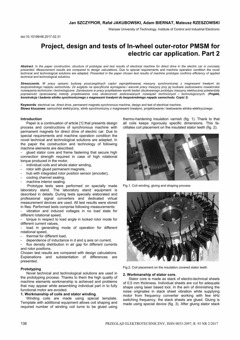
thermo-hardening insulation varnish (fig. 1). Thank to that all coils keeps rigorously specific dimensions. This fa-cilitates coil placement on the insulated stator teeth (fig. 2). Fig.1. Coil winding, gluing and shaping process
Fig.2. Coil placement on the insulation covered stator teeth
2. Workmanship of stator core. Stator core is made as stack of electro-technical sheets of 0,5 mm thickness. Individual sheets are cut for adequate shape using laser based tool. In the aim of diminishing the noise originates in stack sheet vibration while supplying motor from frequency converter working with few kHz switching frequency, the stack sheets are glued. Gluing is made using special device (fig. 3). After gluing stator stack
PRZEGLĄD ELEKTROTECHNICZNY, ISSN 0033-2097, R. 93 NR 2/2017 139
is taken off the device and internal surface precisely processed for adequate fitting to stator frame. Fig.3. Stacking, pressing and gluing process of stator core 3. Encasing of stator core on the frame. After forcing in stator core on frame the core-frame joint is enforced. Enforcing is necessary because of high torque about 500 Nm produced in the machine. Aiming this nine holes uniformly distributed on the core-frame contact surface are drilled along stack (fig. 3). Holes are placed in the teeth axis. Increase of joint strength is achieved by forcing adequately fitted locating pins in to holes (fig. 4). Fig.4. Drilling holes and pin enforcing core-frame joint 4. Magnets mounting. Correct magnet gluing to the rotor frame should secure high shear strength of weld and high precision of magnet distribution along rotor frame perimeter. High weld strength is achieved by using adequate glue and preparation of glued surfaces. Precision of magnet distribution is accomplished by device that allows performing angular rotor displacement of very high accuracy (fig. 5). To increase glue strength space between magnets are filling with resin. Fig.5. Device for uniform magnets distribution and gluing 5. Hub construction. Hub cross-section with marked individual elements are presented on figure 6. The main hub task together with bearing is to secure appropriate positioning of rotor with screwed down car wheel in respect to machine stator fixed to car suspension system. For this reasons hub bearing system has to be resistive to radial and axial forces. Cause of radial forces appearance is the unbalanced magnetic pull between machine rotor and stator, gravity force and dynamic reaction of wheel with ground. Source of axial forces is the wheel reaction during taking a bend and during wheel contact with side obstacles.
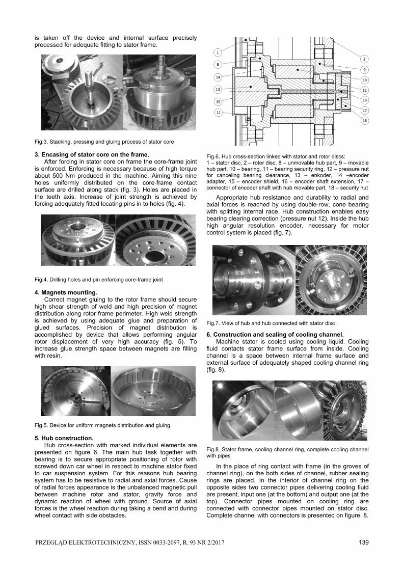
Fig.6. Hub cross-section linked with stator and rotor discs: 1 – stator disc, 2 – rotor disc, 8 – unmovable hub part, 9 – movable hub part, 10 – bearing, 11 – bearing security ring, 12 – pressure nut for canceling bearing clearance, 13 – enkoder, 14 –encoder adapter, 15 – encoder shield, 16 – encoder shaft extension, 17 – connector of encoder shaft with hub movable part, 18 – security nut
Appropriate hub resistance and durability to radial and axial forces is reached by using double-row, cone bearing with splitting internal race. Hub construction enables easy bearing clearing correction (pressure nut 12). Inside the hub high angular resolution encoder, necessary for motor control system is placed (fig. 7).
Fig.7. View of hub and hub connected with stator disc
6. Construction and sealing of cooling channel. Machine stator is cooled using cooling liquid. Cooling fluid contacts stator frame surface from inside. Cooling channel is a space between internal frame surface and external surface of adequately shaped cooling channel ring (fig. 8).
Fig.8. Stator frame, cooling channel ring, complete cooling channel with pipes
In the place of ring contact with frame (in the groves of channel ring), on the both sides of channel, rubber sealing rings are placed. In the interior of channel ring on the opposite sides two connector pipes delivering cooling fluid are present, input one (at the bottom) and output one (at the top). Connector pipes mounted on cooling ring are connected with connector pipes mounted on stator disc. Complete channel with connectors is presented on figure. 8.
140 PRZEGLĄD ELEKTROTECHNICZNY, ISSN 0033-2097, R. 93 NR 2/2017
7. Sealing of machine interior. Machine interior sealing system is placed close to stator disc. Elastic sealing V-ring is used. V-ring is placed on specially shaped socket in the stiffening movable ring fixed to the rotor frame. To the elastic part of sealing ring the unmovable ring fixed to the stator disc adheres. Sealing system is presented on figure 9. Fig.9. Machine interior sealing. 1 – stator disc, 5 – movable stiffening ring, 6 – elastic V-ring, 7 – unmovable sealing ring Complete machine prototype is presented on figure 10. On the suspension side connecting pipes delivering cooling liquid, supplying conductors, and temperature sensors and encoder wires are visible. Between movable and unmovable machine part the sealing ring is visible. Fig.10. Machine prototype, subsequently presented: wheel side view, side view and suspension side view Prototype tests The aim of prototype tests was verification of chosen parameters obtained during designing stage and checking the correctness of adopted constructional solutions. Prototype tests were performed on the specially constructed laboratory stand. During construction of laboratory stand the rule that instantaneous values of measurement signals are to be registered was decided. This enabled to perform measurements both in steady state and dynamic state of operation using the same set of measurement devices. For such assumptions laboratory stand for tests of machine prototype was equipped in following elements, sensors and converters: - Mounting system of tested machine to the stand basis; - System of drive/load shaft end connection with machine rotor that replace wheel rim; - 30,8 kW DC Motor with blower cooling coupled with planetary gearbox with reduction ratio 5:1. DC Motor serves as load or drive for tested prototype depending on mode of operation (motoring or generating); - Rotational torque and speed sensor DATAFLEX 42 with measurement ranges 0-200 Nm or 0-500 Nm, coupled with shaft ends of DC Motor and tested machine prototype with non-slip membrane clutches. Sensor enables torque measurement in normal and locked rotor mode of operation; - Tested machine cooling system consists of cooler, fan and cooling fluid pump. Pump and fan are supplied from
regulated power suppliers that enable control of fluid and air delivery; - Systems for rotor locking and precision change of rotor of tested machine angular position; - System for Hall probe mounting in the air gap and displacement along circumference of tested machine. Moving part is coupled with angular position converter. Hall probe is connected with elaborated supply current stabilizer and output voltage signal conditioning circuit; - Four-quadrants DC thyristor drive controller supplied from three phase power system for supplying armature circuit of DC Motor, regulated excitation current source, high power DC voltage source (5 kW/60 V/85 A) for supplying tested motor on rotor locked mode of operation; - Arrangement of three current/voltage converters Tektronix A622 type of measurement range 0-100 A and three voltage/voltage converters with galvanic separation LEM LV25p type of measurement range 0-500 V; - Converter that converts digital signal from 14 bits absolute encoder mounted in the tested machine in to analog signal; - Arrangement of converters cooperating with temperature sensors LM135 type mounted in the chosen winding and constructional elements spots; - Piezoelectric vibration sensor 4339 Bruel&Kjaer type of sensitivity 9.96 mV/g, screw mounted on special base glued to the machine frame; - Measurement microphone for measurement air pressure changes; - Converter USB-6251 that converts analogue signal from sensors into digital form. Converter is connected with PC using USB bus, equipped with LabVIEW program tool [2]. LabVIEW program tool [1] enables creation of own applications – so called virtual measurement systems, that secure measurement data acquisition, processing and visualization. In the created virtual instruments one can distinguish following blocks: - Acquisition block – enables determination of number of active A/D converter channels, sampling frequency, number of registered samples, rescaling of measurement channels and creation of data files; - Processing block – enables elimination of constant signal component and noise, determination of fundamental frequency, calculation of signal FFT, determination of basic signal measures (mean values, RMS values), mathematical processing (calculation of electrical and mechanical power); - Visualization block – consists of graphical windows that presents signal instantaneous courses and characteristics – dependences between signals and numerical windows that presents digital values of signal measures; - Manipulation buttons that control virtual device functionality e.g. enable start of auto-calibration procedure or adding measured quantities to a file. All described next measurements were made using specially elaborated virtual measurement devices. Its basic structure is the same. Virtual instruments differ depending on realized task. The following measurement tests of machine prototype were performed: - Vibration and induced voltages in no load state for different rotational speed; - Torque in respect to load angle in locked rotor mode for different current values; - Load in generating mode of operation for different rotational speed; - Temperature for different load; - Dependence of inductance in d and q axis on current. - Flux density distribution in air gap for different current;

PRZEGLĄD ELEKTROTECHNICZNY, ISSN 0033-2097, R. 93 NR 2/2017 141
1. Testing of vibration and induced voltages in no load state for different rotational speed
View of laboratory stand for vibration and induced voltage tests is presented on figure 11.
Fig.11. View of laboratory stand for vibration and induced voltage tests Measurements were performed using specially elaborated virtual measurement device that enables: register of instantaneous values of induced voltages, acceleration of stator vibrations, rotational torque acting on rotor of tested machine and instantaneous changes of acoustic pressure – noise created by rotor of tested machine. Measurement device enables writing in to file, data collected during 10 second with sampling frequency 40 kHz. The aim of test was measurement of vibration acceleration of stator evoked by cogging torque and unbalanced magnetic pull between stator and rotor and measurement of induced voltages in no load state. Measurements were performed for few values of rotational velocity from 50 rpm to 450 rpm. Tested motor was drive by DC motor. Apart of vibrations also instantaneous values of induced voltages were registered. On figure 13 spectrum of voltage induced for 450 rpm within range 0,1 Hz to 4 kHz is presented. Fig.12. Stator vibration spectrum from 0.1 Hz to 1 kHz for machine rotational velocities from 50 to 450 rpm
Stator vibration spectrum from 0.1 Hz to 1 kHz for few machine rotational velocities is presented on figure 12. Picture reveals existence of vibrations of frequency depending and independent on rotational speed. Vibration frequency components depending on rotational velocity are defined by multiples of product of rotational frequency fr and number of stator teeth N1. This vibrations result from cogging torque which frequency is N1. Its amplitudes are dominating and increase with rotational velocity increase,
but do not exceed 0,015 m/s2. Cause of vibrations independent on rotational velocity is drive torque pulsations which armature was feed from DC thyristor drive controller. This kind of supply results in existence of current and torque pulsations frequencies that are multiples of mains frequency 50 Hz. Another cause of vibrations independent on rotational speed are structural resonant frequencies of machine construction and stand basis. In the full range spectrum these vibrations appears within ranges (500-2000 Hz) and (6500-10000 Hz). Fig.13. Spectrum of voltage induced for 450 rpm within range 0,1 Hz to 4 kHz, numbers mark subsequent higher harmonics
Picture reveals that amplitudes of higher harmonics do not exceed 0.5% of fundamental harmonic. Difference of amplitudes of individual phase voltages do not exceeds 1,5%. Differences between amplitudes of individual phase voltages calculated and measured do not exceed 5%. The main reason of divergences is differences between real and claimed by producer demagnetization magnet characteristics.
2. Testing of torque in respect to load angle in locked rotor mode for different current values Laboratory stand enables determination of electromagnetic torque characteristics in respect on rotor angular position for locked rotor mode and fixed, defined current values in phase belts. View of systems for rotor locking and precision change of rotor of tested machine angular position is presented on figure 14. Fig.14. View of systems for rotor locking and change of rotor of angular position, connected with torque sensor Measurements were performed using virtual measurement device that enables: register of rotor angular position, electromagnetic torque and maximal value of chosen phase current. Moreover in the digital windows the maximal winding temperature is presented. Phase belts were feed from high power regulated DC supply with current limitation. Thank to this the constant current value not affected by increasing of winding resistance with temperature increase. After setting chosen rotor position using screw gear and pushing virtual “measure” button collected data – angular position, torque and current is added to measurement file as a new row. After each
142 PRZEGLĄD ELEKTROTECHNICZNY, ISSN 0033-2097, R. 93 NR 2/2017
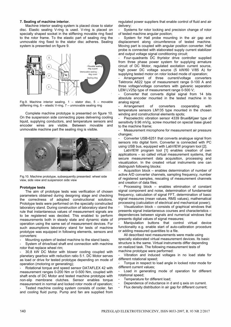
measurement the updated torque characteristic in form of broken line connecting points which co-ordinates are results of subsequent measurements. Fig.15. Characteristics of rotational torque on angular rotor position for zero phase belts current values and clockwise (Tr) and anticlockwise (Tl) directions of rotor angular position changes, Tf – friction torque, Taf – mean value of friction torque Fig.16. Characteristics of rotational torque in respect to rotor position
On figure 15 the characteristics of rotational torque on angular rotor position for zero phase belts current values and clockwise (Tr) and anticlockwise (Tl) directions of rotor angular position changes are presented. Figure reveals that in the tested machine the cogging torque of amplitude 0,7 Nm and periodicity equal to stator grove pitch exists. Experimentally determined cogging torque is much higher and has greater periodicity of changes that calculated cogging torque. So great value of cogging torque of periodicity equal to tooth pitch, is caused by differences in dimensions, individual rotor magnets magnetization and no-idealities in symmetrical magnet distribution along rotor circumference. Shift of measured characteristics for different direction of rotor angular changes is caused by friction torque in the machine bearing system. Determined mean value of friction torque is about 2 Nm.
On figure 16 the measured dependence of electromagnetic torque in respect to rotor angular position for feeding 1st phase belt and parallel connected 2nd and 3rd phase belts with currents of different multiplication (1, 2, 3,
3,5) of nominal current are presented. Figure shows that dependence of maximal values of torque on currents is nearly linear. Performed tests reveals that according to presumed requirements there is possible over three times torque overload of designed and build machine. Measured value of rotational torque is by 3% bigger than torque calculated during designing.
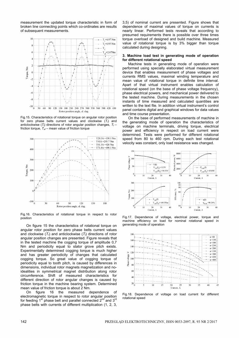
3. Machine load test in generating mode of operation for different rotational speed Machine tests in generating mode of operation were performed using specially elaborated virtual measurement device that enables measurement of phase voltages and currents RMS values, maximal winding temperature and mean value of rotational torque in definite time interval. Apart of that virtual instrument enables calculation of rotational speed (on the base of phase voltage frequency), phase electrical powers, and mechanical power delivered to the tested machine. During measurements in the chosen instants of time measured and calculated quantities are written to the text file. In addition virtual instrument’s control panel contains digital and graphical windows for data values and time course presentation. On the base of performed measurements of machine in the generating mode of operation the characteristics of voltage on machine terminals, driving torque, electrical power and efficiency in respect on load current were determined. Tests were performed for different rotational speed from 80 to 460 rpm. During each test rotational velocity was constant, only load resistance was changed. Fig.17. Dependence of voltage, electrical power, torque and machine efficiency on load for nominal rotational speed in generating mode of operation Fig.18. Dependence of voltage on load current for different rotational speed
PRZEGLĄD ELEKTROTECHNICZNY, ISSN 0033-2097, R. 93 NR 2/2017 143
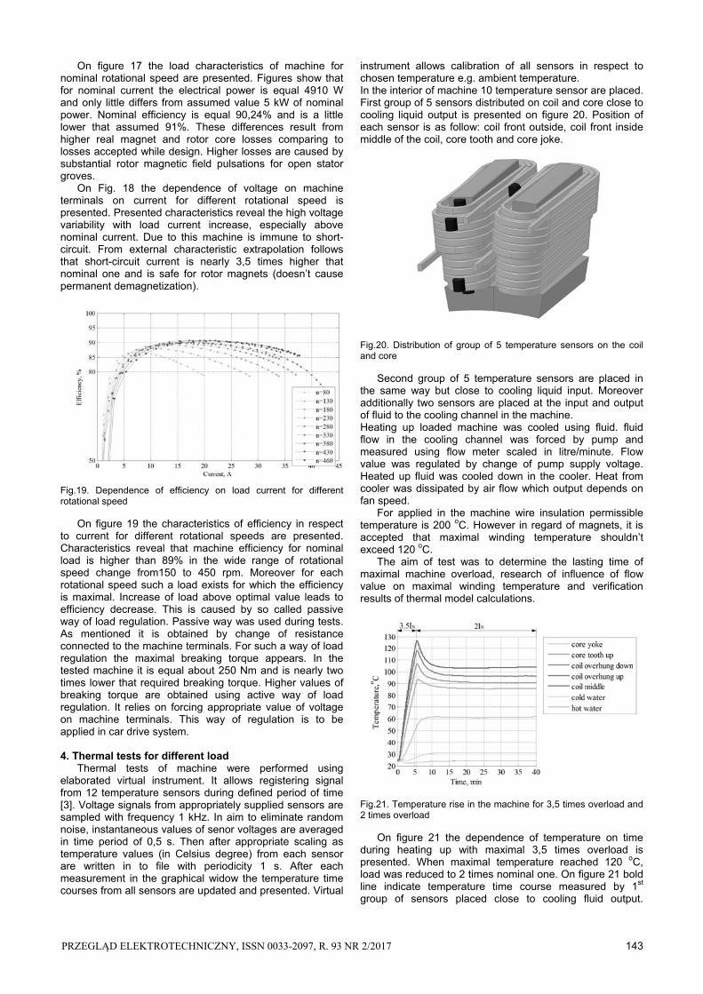
On figure 17 the load characteristics of machine for nominal rotational speed are presented. Figures show that for nominal current the electrical power is equal 4910 W and only little differs from assumed value 5 kW of nominal power. Nominal efficiency is equal 90,24% and is a little lower that assumed 91%. These differences result from higher real magnet and rotor core losses comparing to losses accepted while design. Higher losses are caused by substantial rotor magnetic field pulsations for open stator groves. On Fig. 18 the dependence of voltage on machine terminals on current for different rotational speed is presented. Presented characteristics reveal the high voltage variability with load current increase, especially above nominal current. Due to this machine is immune to short-circuit. From external characteristic extrapolation follows that short-circuit current is nearly 3,5 times higher that nominal one and is safe for rotor magnets (doesn’t cause permanent demagnetization). Fig.19. Dependence of efficiency on load current for different rotational speed
On figure 19 the characteristics of efficiency in respect to current for different rotational speeds are presented. Characteristics reveal that machine efficiency for nominal load is higher than 89% in the wide range of rotational speed change from150 to 450 rpm. Moreover for each rotational speed such a load exists for which the efficiency is maximal. Increase of load above optimal value leads to efficiency decrease. This is caused by so called passive way of load regulation. Passive way was used during tests. As mentioned it is obtained by change of resistance connected to the machine terminals. For such a way of load regulation the maximal breaking torque appears. In the tested machine it is equal about 250 Nm and is nearly two times lower that required breaking torque. Higher values of breaking torque are obtained using active way of load regulation. It relies on forcing appropriate value of voltage on machine terminals. This way of regulation is to be applied in car drive system.
4. Thermal tests for different load Thermal tests of machine were performed using elaborated virtual instrument. It allows registering signal from 12 temperature sensors during defined period of time [3]. Voltage signals from appropriately supplied sensors are sampled with frequency 1 kHz. In aim to eliminate random noise, instantaneous values of senor voltages are averaged in time period of 0,5 s. Then after appropriate scaling as temperature values (in Celsius degree) from each sensor are written in to file with periodicity 1 s. After each measurement in the graphical widow the temperature time courses from all sensors are updated and presented. Virtual
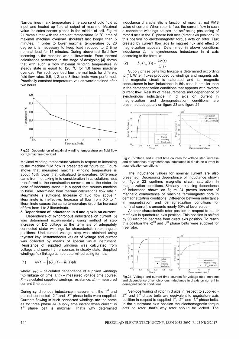
instrument allows calibration of all sensors in respect to chosen temperature e.g. ambient temperature. In the interior of machine 10 temperature sensor are placed. First group of 5 sensors distributed on coil and core close to cooling liquid output is presented on figure 20. Position of each sensor is as follow: coil front outside, coil front inside middle of the coil, core tooth and core joke. Fig.20. Distribution of group of 5 temperature sensors on the coil and core
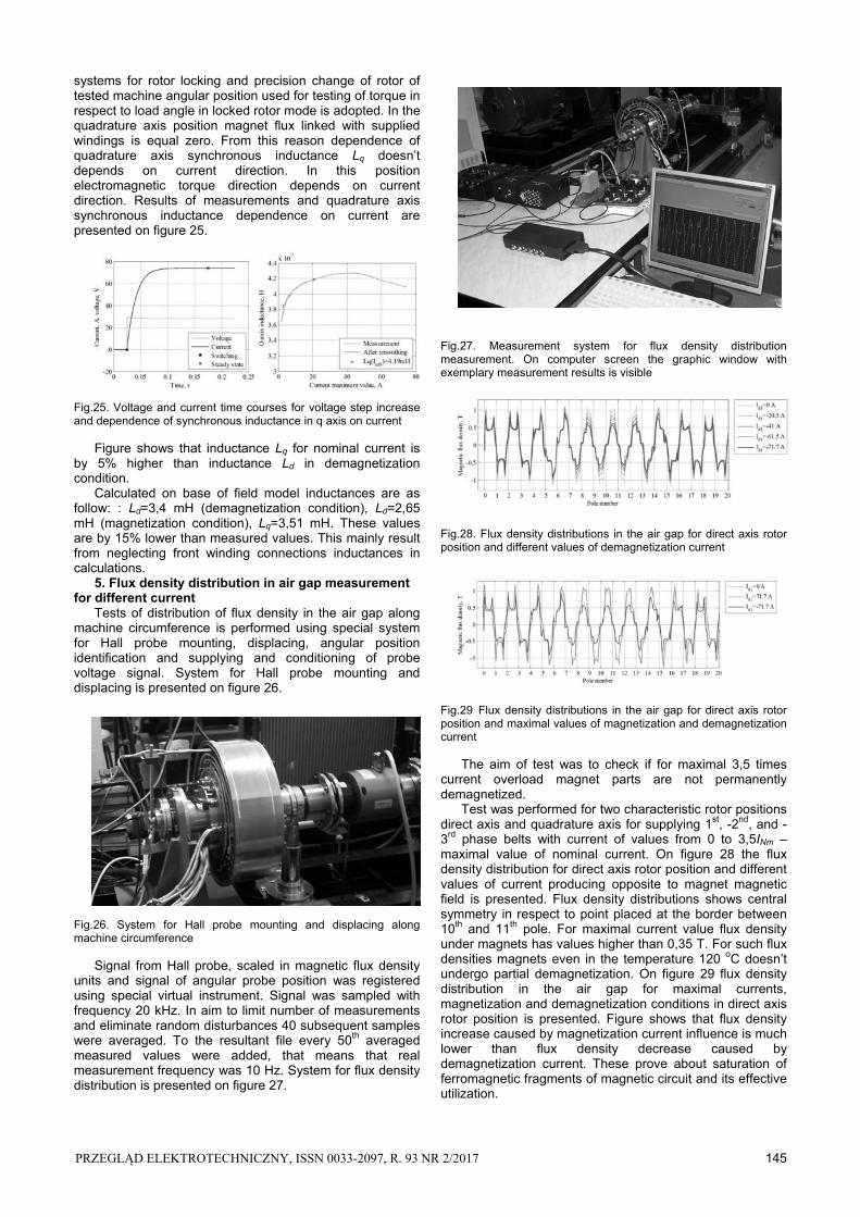
Second group of 5 temperature sensors are placed in the same way but close to cooling liquid input. Moreover additionally two sensors are placed at the input and output of fluid to the cooling channel in the machine. Heating up loaded machine was cooled using fluid. fluid flow in the cooling channel was forced by pump and measured using flow meter scaled in litre/minute. Flow value was regulated by change of pump supply voltage. Heated up fluid was cooled down in the cooler. Heat from cooler was dissipated by air flow which output depends on fan speed. For applied in the machine wire insulation permissible temperature is 200 oC. However in regard of magnets, it is accepted that maximal winding temperature shouldn’t exceed 120 oC. The aim of test was to determine the lasting time of maximal machine overload, research of influence of flow value on maximal winding temperature and verification results of thermal model calculations. Fig.21. Temperature rise in the machine for 3,5 times overload and 2 times overload On figure 21 the dependence of temperature on time during heating up with maximal 3,5 times overload is presented. When maximal temperature reached 120 oC, load was reduced to 2 times nominal one. On figure 21 bold line indicate temperature time course measured by 1st group of sensors placed close to cooling fluid output.
144 PRZEGLĄD ELEKTROTECHNICZNY, ISSN 0033-2097, R. 93 NR 2/2017
Narrow lines mark temperature time course of cold fluid at input and heated up fluid at output of machine. Maximal value indicates sensor placed in the middle of coil. Figure 21 reveals that with the ambient temperature 25 oC, time of maximal machine overload shouldn’t last longer than 5 minutes. In order to lower maximal temperature by 20 degree it is necessary to keep load reduced to 2 time nominal load for 15 minutes. During above test fluid flow incoming to the machine was 1 liter/minute. From thermal calculations performed in the stage of designing [4] shows that with such a flow maximal winding temperature in steady state is equal to 120 oC for 1,8 times machine overload. For such overload four thermal tests for different fluid flow rates: 0,5, 1, 2, and 3 liter/minute were performed. Practically constant temperature values were obtained after two hours. Fig.22. Dependence of maximal winding temperature on fluid flow for 1,8 machine overload Maximal winding temperature values in respect to incoming to the machine fluid flow is presented on figure 22. Figure shows that measured maximal winding temperature is about 10% lower that calculated temperature. Difference cams from not taking in to consideration in calculations heat transferred to the construction screwed on to the stator. In case of laboratory stand it is support that mounts machine to base. Determined from thermal calculations flow rate 1 liter/minute is sufficient. Increase of fluid flow above 1 liter/minute is ineffective. Increase of flow from 0,5 to 1 liter/minute causes the same temperature drop like increase of flow from 1 to 3 liter/minute. 5. Dependence of inductance in d and q axis on current Dependence of synchronous inductance on current [5] was determined experimentally using method of step increase of DC voltage at the terminals of adequately connected stator windings for characteristic rotor angular positions. Undisturbed voltage step was obtained using thyristor key. Instantaneous values of voltage and current was collected by means of special virtual instrument. Resistance of supplied windings was calculated from voltage and current time courses in steady state. Supplied windings flux linkage can be determined using formula:
(1) t
z ttRitUt0
d))()(()(
where: ψ(t) – calculated dependence of supplied windings flux linkage on time, Uz(t) – measured voltage time course, R – calculated supplied windings resistance, i(t) – measured current time course. During synchronous inductance measurement the 1st and parallel connected -2nd and -3rd phase belts were supplied. Currents flowing in such connected windings are the same as for three phase AC supply time instant when current in 1st phase belt is maximal. That’s why determined
inductance characteristic is function of maximal, not RMS value of current. When rotor is free, the current flow in such a connected windings causes the self-acting positioning of rotor d axis in the 1st phase belt axis (direct axis position). In this position no electromagnetic torque acts on rotor. Flux created by current flow ads to magnet flux and effect of magnetization appears. Determined in above conditions inductance Ld. is synchronous inductance in d axis according to the formula:
(2) )(3
)(2))((
ti
ttiL md
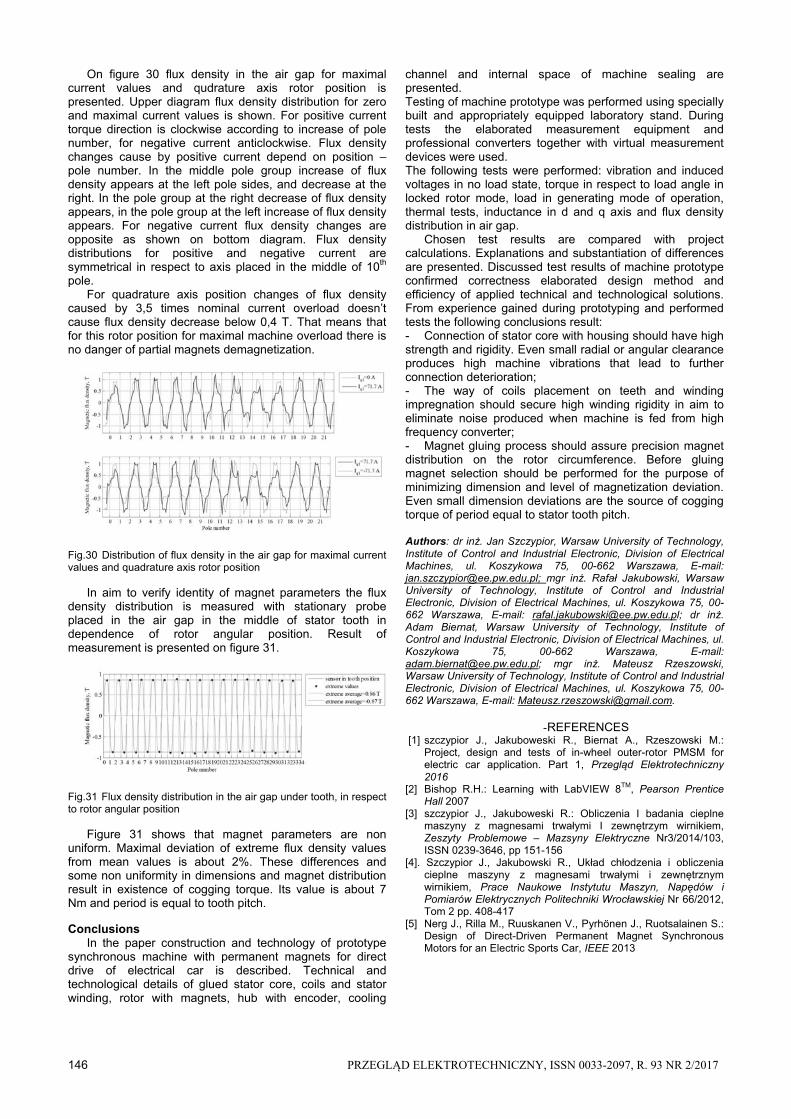
Supply phase belts flux linkage is determined according to (1). When fluxes produced by windings and magnets ads the magnetic circuit is saturated and its magnetic conductance is low. Inductance in this case is smaller than in the demagnetization conditions that appears with reverse current flow. Results of measurements and dependence of synchronous inductance in d axis on current in magnetization and demagnetization conditions are presented adequately on figure 23 and figure 24. Fig.23. Voltage and current time courses for voltage step increase and dependence of synchronous inductance in d axis on current in magnetization conditions The inductance values for nominal current are also presented. Decreasing dependence of inductance shown on figure 23 confirms magnetic circuit saturation in magnetization conditions. Similarly increasing dependence of inductance shown on figure 24 proves increase of magnetic conductance of machine ferromagnetic core in demagnetization conditions. Difference between inductance in magnetization and demagnetization conditions for nominal current is amounts nearly 50% of lover value. Another characteristic rotor position in respect to stator mmf axis is quadrature axis position. This position is shifted by 90 electrical degrees from direct axis position. To reach this position the -2nd and 3rd phase belts were supplied for free rotor. Fig.24. Voltage and current time courses for voltage step increase and dependence of synchronous inductance in d axis on current in demagnetization conditions
Self-positioning of rotor in d axis in respect to supplied -2nd and 3rd phase belts are equivalent to quadrature axis position in respect to supplied 1st, -2nd and -3rd phase belts. In the quadrature axis position the electromagnetic torque acts on rotor, that’s why rotor should be locked. The
PRZEGLĄD ELEKTROTECHNICZNY, ISSN 0033-2097, R. 93 NR 2/2017 145
systems for rotor locking and precision change of rotor of tested machine angular position used for testing of torque in respect to load angle in locked rotor mode is adopted. In the quadrature axis position magnet flux linked with supplied windings is equal zero. From this reason dependence of quadrature axis synchronous inductance Lq doesn’t depends on current direction. In this position electromagnetic torque direction depends on current direction. Results of measurements and quadrature axis synchronous inductance dependence on current are presented on figure 25. Fig.25. Voltage and current time courses for voltage step increase and dependence of synchronous inductance in q axis on current Figure shows that inductance Lq for nominal current is by 5% higher than inductance Ld in demagnetization condition. Calculated on base of field model inductances are as follow: : Ld=3,4 mH (demagnetization condition), Ld=2,65 mH (magnetization condition), Lq=3,51 mH. These values are by 15% lower than measured values. This mainly result from neglecting front winding connections inductances in calculations. 5. Flux density distribution in air gap measurement for different current Tests of distribution of flux density in the air gap along machine circumference is performed using special system for Hall probe mounting, displacing, angular position identification and supplying and conditioning of probe voltage signal. System for Hall probe mounting and displacing is presented on figure 26. Fig.26. System for Hall probe mounting and displacing along machine circumference Signal from Hall probe, scaled in magnetic flux density units and signal of angular probe position was registered using special virtual instrument. Signal was sampled with frequency 20 kHz. In aim to limit number of measurements and eliminate random disturbances 40 subsequent samples were averaged. To the resultant file every 50th averaged measured values were added, that means that real measurement frequency was 10 Hz. System for flux density distribution is presented on figure 27.
Fig.27. Measurement system for flux density distribution measurement. On computer screen the graphic window with exemplary measurement results is visible Fig.28. Flux density distributions in the air gap for direct axis rotor position and different values of demagnetization current Fig.29 Flux density distributions in the air gap for direct axis rotor position and maximal values of magnetization and demagnetization current The aim of test was to check if for maximal 3,5 times current overload magnet parts are not permanently demagnetized. Test was performed for two characteristic rotor positions direct axis and quadrature axis for supplying 1st, -2nd, and -3rd phase belts with current of values from 0 to 3,5INm – maximal value of nominal current. On figure 28 the flux density distribution for direct axis rotor position and different values of current producing opposite to magnet magnetic field is presented. Flux density distributions shows central symmetry in respect to point placed at the border between 10th and 11th pole. For maximal current value flux density under magnets has values higher than 0,35 T. For such flux densities magnets even in the temperature 120 oC doesn’t undergo partial demagnetization. On figure 29 flux density distribution in the air gap for maximal currents, magnetization and demagnetization conditions in direct axis rotor position is presented. Figure shows that flux density increase caused by magnetization current influence is much lower than flux density decrease caused by demagnetization current. These prove about saturation of ferromagnetic fragments of magnetic circuit and its effective utilization.
146 PRZEGLĄD ELEKTROTECHNICZNY, ISSN 0033-2097, R. 93 NR 2/2017
On figure 30 flux density in the air gap for maximal current values and qudrature axis rotor position is presented. Upper diagram flux density distribution for zero and maximal current values is shown. For positive current torque direction is clockwise according to increase of pole number, for negative current anticlockwise. Flux density changes cause by positive current depend on position – pole number. In the middle pole group increase of flux density appears at the left pole sides, and decrease at the right. In the pole group at the right decrease of flux density appears, in the pole group at the left increase of flux density appears. For negative current flux density changes are opposite as shown on bottom diagram. Flux density distributions for positive and negative current are symmetrical in respect to axis placed in the middle of 10th pole. For quadrature axis position changes of flux density caused by 3,5 times nominal current overload doesn’t cause flux density decrease below 0,4 T. That means that for this rotor position for maximal machine overload there is no danger of partial magnets demagnetization. Fig.30 Distribution of flux density in the air gap for maximal current values and quadrature axis rotor position In aim to verify identity of magnet parameters the flux density distribution is measured with stationary probe placed in the air gap in the middle of stator tooth in dependence of rotor angular position. Result of measurement is presented on figure 31. Fig.31 Flux density distribution in the air gap under tooth, in respect to rotor angular position Figure 31 shows that magnet parameters are non uniform. Maximal deviation of extreme flux density values from mean values is about 2%. These differences and some non uniformity in dimensions and magnet distribution result in existence of cogging torque. Its value is about 7 Nm and period is equal to tooth pitch. Conclusions In the paper construction and technology of prototype synchronous machine with permanent magnets for direct drive of electrical car is described. Technical and technological details of glued stator core, coils and stator winding, rotor with magnets, hub with encoder, cooling
channel and internal space of machine sealing are presented. Testing of machine prototype was performed using specially built and appropriately equipped laboratory stand. During tests the elaborated measurement equipment and professional converters together with virtual measurement devices were used. The following tests were performed: vibration and induced voltages in no load state, torque in respect to load angle in locked rotor mode, load in generating mode of operation, thermal tests, inductance in d and q axis and flux density distribution in air gap. Chosen test results are compared with project calculations. Explanations and substantiation of differences are presented. Discussed test results of machine prototype confirmed correctness elaborated design method and efficiency of applied technical and technological solutions. From experience gained during prototyping and performed tests the following conclusions result: - Connection of stator core with housing should have high strength and rigidity. Even small radial or angular clearance produces high machine vibrations that lead to further connection deterioration; - The way of coils placement on teeth and winding impregnation should secure high winding rigidity in aim to eliminate noise produced when machine is fed from high frequency converter; - Magnet gluing process should assure precision magnet distribution on the rotor circumference. Before gluing magnet selection should be performed for the purpose of minimizing dimension and level of magnetization deviation. Even small dimension deviations are the source of cogging torque of period equal to stator tooth pitch. Authors: dr inż. Jan Szczypior, Warsaw University of Technology, Institute of Control and Industrial Electronic, Division of Electrical Machines, ul. Koszykowa 75, 00-662 Warszawa, E-mail: [email protected]; mgr inż. Rafał Jakubowski, Warsaw University of Technology, Institute of Control and Industrial Electronic, Division of Electrical Machines, ul. Koszykowa 75, 00-662 Warszawa, E-mail: [email protected]; dr inż. Adam Biernat, Warsaw University of Technology, Institute of Control and Industrial Electronic, Division of Electrical Machines, ul. Koszykowa 75, 00-662 Warszawa, E-mail: [email protected]; mgr inż. Mateusz Rzeszowski, Warsaw University of Technology, Institute of Control and Industrial Electronic, Division of Electrical Machines, ul. Koszykowa 75, 00-662 Warszawa, E-mail: [email protected].
- REFERENCES [1] szczypior J., Jakuboweski R., Biernat A., Rzeszowski M.:
Project, design and tests of in-wheel outer-rotor PMSM for electric car application. Part 1, Przegląd Elektrotechniczny 2016
[2] Bishop R.H.: Learning with LabVIEW 8TM, Pearson Prentice Hall 2007
[3] szczypior J., Jakuboweski R.: Obliczenia I badania cieplne maszyny z magnesami trwałymi I zewnętrzym wirnikiem, Zeszyty Problemowe – Mazsyny Elektryczne Nr3/2014/103, ISSN 0239-3646, pp 151-156
[4]. Szczypior J., Jakubowski R., Układ chłodzenia i obliczenia cieplne maszyny z magnesami trwałymi i zewnętrznym wirnikiem, Prace Naukowe Instytutu Maszyn, Napędów i Pomiarów Elektrycznych Politechniki Wrocławskiej Nr 66/2012, Tom 2 pp. 408-417
[5] Nerg J., Rilla M., Ruuskanen V., Pyrhönen J., Ruotsalainen S.: Design of Direct-Driven Permanent Magnet Synchronous Motors for an Electric Sports Car, IEEE 2013