Method of increasing the reliability and safety of the ... · According to presented by ABB data,...
10
EKSPLOATACJA I NIEZAWODNOSC – MAINTENANCE AND RELIABILITY VOL.17, NO. 3, 2015 398 Article citation info: (*) Tekst artykułu w polskiej wersji językowej dostępny w elektronicznym wydaniu kwartalnika na stronie www.ein.org.pl PAWLAK M, KOśCIELNY JM, WASIEWICZ P. Method of increasing the reliability and safety of the processes through the use of fault tolerant con- trol systems. Eksploatacja i Niezawodnosc – Maintenance and Reliability 2015; 17 (3): 398–407, http://dx.doi.org/10.17531/ein.2015.3.10. Mariusz PAWLAK Jan Maciej KOśCIELNY Piotr WASIEWICZ METHOD OF INCREASING THE RELIABILITY AND SAFETY OF THE PROCESSES THROUGH THE USE OF FAULT TOLERANT CONTROL SYSTEMS METODA PODWYżSZANIA NIEZAWODNOśCI I BEZPIECZEńSTWA PROCESóW POPRZEZ STOSOWANIE UKłADóW REGULACJI TOLERUJąCYCH USZKODZENIA* The operation idea of fault tolerant control systems, has been presented in the paper. Protection and security layers applied in technical diagnostics associated with safety of control system, have been discussed. The automatic control system of a steam tur- bine power, has been described as an example of fault tolerant control system. A steam turbine is the main element of energy blocs forming a national energy system. Therefore, the turbine control systems require high reliability. The impact of diagnostics and fault tolerance on the values of reliability and safety coefficients of control systems, have been determined in the paper. Keywords: control system, functional safety, protection and security layers, diagnostics, fault tolerance, redun- dancy, reconfiguration, reliability and safety coefficients, energetic block, steam turbine. Przedstawiono ideę działania układów automatyki tolerujących uszkodzenia. Omówiono warstwy zabezpieczeniowo ochronne stosowane w diagnostyce technicznej, związanej z bezpieczeństwem układów regulacji. Jako przykład układu regulacji toleru- jącego uszkodzenia torów pomiarowych, opisano układ regulacji mocy turbiny parowej. Turbiny takie stanowią podstawowy element bloków energetycznych, tworzących krajowy system energetyczny. Dlatego też, od układów regulacji turbin wymaga się dużej niezawodności. W pracy określono wpływ diagnostyki i tolerowania uszkodzeń na wartości wskaźników niezawodności i bezpieczeństwa układów automatyki. Słowa kluczowe: bezpieczeństwo, diagnostyka, układ regulacji, tolerowanie uszkodzeń, redundancja, rekonfigu- racja, turbina parowa, blok energetyczny, wskaźniki niezawodności. 1. Introduction The control system faults are one of the main causes of break- downs in industrial processes. According to presented by ABB data, 36% of all problems are caused by failures of control system compo- nents, including faults of sensors and actuators primarily. These de- vices are installed on the process installation, which creates for them difficult and variable operating conditions. Control units, installed in the control rooms, are damaged relatively rare. If we consider dam- ages caused by control systems exclusively , then not more than 10% of them are caused by faults of control units. The others are the con- sequences of faults of sensors and actuators. In contrast, paradoxi- cally different redundant solutions are developed and are commer- cially available primarily for any kind of controllers and computer networks. Examples of serious industrial accidents caused by damage to the measuring equipment are: Damage in the fuel storage Buncefield, on 11 December 2005. • A fault of the level sensor caused overflow of the fuel tank and ignition. Next, a series of explosions and fire of aviation fuel occurred. It was the largest fire in Europe. There were 40 injuries and substantial material damage (£ 5bn) [1]. Damage in Texas City, USA, on 23 March 2005, in the largest • oil refinery BP International. During a start-up procedure of the separator plant at the Isomerization Department, produc- ing high octane unleaded gasoline additives, level sensors have failed. It caused the level overflow in the distillation column, resulting in a rapid evaporation, a pressure increase, a raffinate ejections, and consequently explosion and fire. 15 people were killed and 170 were injured. Separator plant and evaporation of hydrocarbons plant were destroyed [2]. The need to ensure an adequate level of security, i.e. reducing the risk to an acceptable level, was the cause of the development of in- ternational standards of functional safety. Functional safety related to all activities in the life cycle of the E/E/PE control systems (contain- ing the electrical/ electronic/ programmable electronic components), constitutes an important aspect of functional safety. Various standards have been developed, e.g. in the area of general principles of func- tional safety - IEC 61508 [11,20,21], in the field of industrial proc- esses - EN 61511, in the scope of machines - EN 62061 [12] and in the scope of nuclear energy - IEC 61513. The most important is the new version of IEC 61508 standard [21]. It was adopted as a European standard EN 61508, and next as a national standard PN-EN 61508 [33]. IEC 61511 standard is cur- rently being updated and will be published with a delay as a European standard (EN) and national (EN). It contains a number of additions and refers more broadly to the current IEC 61508 standard, mainly of its parts 5, 6 and 7. New versions of these standards broadly include theoretical issues (numerous citation of recognized publications) and the requirements for mathematical models in terms of verification and validation of the proposed solutions [21].
Transcript of Method of increasing the reliability and safety of the ... · According to presented by ABB data,...
Eksploatacja i NiEzawodNosc – MaiNtENaNcE aNd REliability Vol.17, No. 3, 2015398
Article citation info:
(*) Tekst artykułu w polskiej wersji językowej dostępny w elektronicznym wydaniu kwartalnika na stronie www.ein.org.pl
PAwlAk M, kościelny JM, wAsiewicz P. Method of increasing the reliability and safety of the processes through the use of fault tolerant con-trol systems. eksploatacja i niezawodnosc – Maintenance and Reliability 2015; 17 (3): 398–407, http://dx.doi.org/10.17531/ein.2015.3.10.
Mariusz PAwlAkJan Maciej kościelnyPiotr wAsiewicz
Method of increasing the reliability and safety of the processes through the use of fault tolerant control systeMs
Metoda podwyższania niezawodności i bezpieczeństwa procesów poprzez stosowanie układów regulacji tolerujących uszkodzenia*
The operation idea of fault tolerant control systems, has been presented in the paper. Protection and security layers applied in technical diagnostics associated with safety of control system, have been discussed. The automatic control system of a steam tur-bine power, has been described as an example of fault tolerant control system. A steam turbine is the main element of energy blocs forming a national energy system. Therefore, the turbine control systems require high reliability. The impact of diagnostics and fault tolerance on the values of reliability and safety coefficients of control systems, have been determined in the paper.
Keywords: control system, functional safety, protection and security layers, diagnostics, fault tolerance, redun-dancy, reconfiguration, reliability and safety coefficients, energetic block, steam turbine.
Przedstawiono ideę działania układów automatyki tolerujących uszkodzenia. Omówiono warstwy zabezpieczeniowo ochronne stosowane w diagnostyce technicznej, związanej z bezpieczeństwem układów regulacji. Jako przykład układu regulacji toleru-jącego uszkodzenia torów pomiarowych, opisano układ regulacji mocy turbiny parowej. Turbiny takie stanowią podstawowy element bloków energetycznych, tworzących krajowy system energetyczny. Dlatego też, od układów regulacji turbin wymaga się dużej niezawodności. W pracy określono wpływ diagnostyki i tolerowania uszkodzeń na wartości wskaźników niezawodności i bezpieczeństwa układów automatyki.
Słowa kluczowe: bezpieczeństwo, diagnostyka, układ regulacji, tolerowanie uszkodzeń, redundancja, rekonfigu-racja, turbina parowa, blok energetyczny, wskaźniki niezawodności.
1. Introduction
The control system faults are one of the main causes of break-downs in industrial processes. According to presented by ABB data, 36% of all problems are caused by failures of control system compo-nents, including faults of sensors and actuators primarily. These de-vices are installed on the process installation, which creates for them difficult and variable operating conditions. Control units, installed in the control rooms, are damaged relatively rare. If we consider dam-ages caused by control systems exclusively, then not more than 10% of them are caused by faults of control units. The others are the con-sequences of faults of sensors and actuators. In contrast, paradoxi-cally different redundant solutions are developed and are commer-cially available primarily for any kind of controllers and computer networks.
Examples of serious industrial accidents caused by damage to the measuring equipment are:
Damage in the fuel storage Buncefield, on 11 December 2005. •A fault of the level sensor caused overflow of the fuel tank and ignition. Next, a series of explosions and fire of aviation fuel occurred. It was the largest fire in Europe. There were 40 injuries and substantial material damage (£ 5bn) [1].Damage in Texas City, USA, on 23 March 2005, in the largest •oil refinery BP International. During a start-up procedure of the separator plant at the Isomerization Department, produc-ing high octane unleaded gasoline additives, level sensors have
failed. It caused the level overflow in the distillation column, resulting in a rapid evaporation, a pressure increase, a raffinate ejections, and consequently explosion and fire. 15 people were killed and 170 were injured. Separator plant and evaporation of hydrocarbons plant were destroyed [2].
The need to ensure an adequate level of security, i.e. reducing the risk to an acceptable level, was the cause of the development of in-ternational standards of functional safety. Functional safety related to all activities in the life cycle of the E/E/PE control systems (contain-ing the electrical/ electronic/ programmable electronic components), constitutes an important aspect of functional safety. Various standards have been developed, e.g. in the area of general principles of func-tional safety - IEC 61508 [11,20,21], in the field of industrial proc-esses - EN 61511, in the scope of machines - EN 62061 [12] and in the scope of nuclear energy - IEC 61513.
The most important is the new version of IEC 61508 standard [21]. It was adopted as a European standard EN 61508, and next as a national standard PN-EN 61508 [33]. IEC 61511 standard is cur-rently being updated and will be published with a delay as a European standard (EN) and national (EN). It contains a number of additions and refers more broadly to the current IEC 61508 standard, mainly of its parts 5, 6 and 7. New versions of these standards broadly include theoretical issues (numerous citation of recognized publications) and the requirements for mathematical models in terms of verification and validation of the proposed solutions [21].
Eksploatacja i NiEzawodNosc – MaiNtENaNcE aNd REliability Vol.17, No. 3, 2015 399
sciENcE aNd tEchNology
The concept of Fault Tolerant Control Systems (FTCS), has been discussed in the paper. According to the authors, these systems could provide a new protection layer within the meaning of the standards associated with the functional safety. Mainly faults of sensors and ac-tuators are taken into account in FTC systems, which leads to a sig-nificant value increase of the reliability and safety coefficients of the control systems and thus of the whole process. An exemplary control system of the condensing turbine tolerating sensor faults, has been presented in the paper [29-32, 41]. The influence of diagnosis and fault tolerance on values of the reliability and safety coefficients, has been also discussed.
2. Protection layers
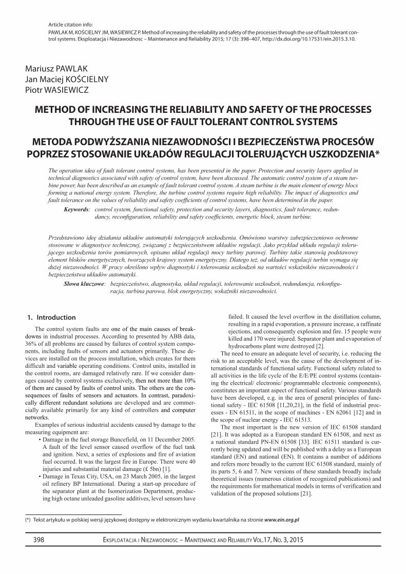
The purpose of safety-related control systems is to reduce the risk, and thus to decrease the frequency of occurrence of dangerous events or to reduce the effects of such events.The applied security systems have a layered structure as shown in Fig.1.
The first layer represents the process installation, which should be resistant to internal and external disturbances (security actions and technological blockades). The second layer is represented by a basic process control system (BPCS). It can be Distributed Control Sys-tem (DCS), which integrates a control and monitoring tasks or system consisting of Supervisory Control and Data Acquisition (SCADA) and PLC/PAC (Programmable Logic Control-ler/Programmable Automation Controller). The third layer is a separate alarm system and operator’s intervention. SIS (Safety Instru-mented System) constitutes the fourth layer. The aim of these four mentioned above layers is to prevent the occurrence of failures. The fifth layer engineering security systems, such as the safety valves, curtains, protective barri-ers, housing, etc., which aim is to reduce the effects of damage occurred. Even higher lay-ers realize internal and external procedures, and technical measures, whose aim is to mini-mize human and material losses.
Commonly used SIS systems implement the safety automatic algorithms and the acti-vation of blockades, whose task is to achieve the proper process operation. Signals gener-ated by SIS systems, for instance, cut off sup-ply or raw materials, block actuators in a safe position, run the shut-off valves, set a safe op-erating status of engines, pumps, ventilators, etc. Usually, SIS actions are associated with shut-off a part of the process installation or even the whole process, which leads to eco-nomic losses.
Therefore, in the lower layers (1, 2 and 3), it is advisable to use solutions that can guarantee the elimination of hazards in the early stages of their development. Methods of reducing the risk, which do not caused the process shut-off, are:
Robust construction of process installation thanks to solid de-1. sign and high quality building and exploitation; passive solu-tions are used, which do not require any control as well as any operator’s intervention to avoid the dangerous situations,Hardware and software redundancy of the control system ele-2. ments,Separate alarm-3. advisory systems,Appropriately designed process visualization,4. Training of operators, especially with use of process simula-5. tors, based on which the various emergency scenarios can be applied,On-line 6. diagnosis systems of the process and automation field devices,Fault tolerant control systems (FTCS).7.
The first four solutions are commonly known and used. While the others are recently developed intensively [13,21,28]. The last three of the methods listed above are not covered sufficiently in safety stand-ards.
3. Idea of fault tolerant control systems
The fault tolerant control algorithms are currently one of the most important directions of research and development in the field of au-tomation. They were discussed, among others, in monographs [3, 8, 9, 13, 18, 25, 28, 36]. The first works on the FTC focused on the aerospace industry. Nowadays, however, in addition to applications in aircrafts, FTC systems are designed for industrial processes more frequently [14-16, 39, 38-41].
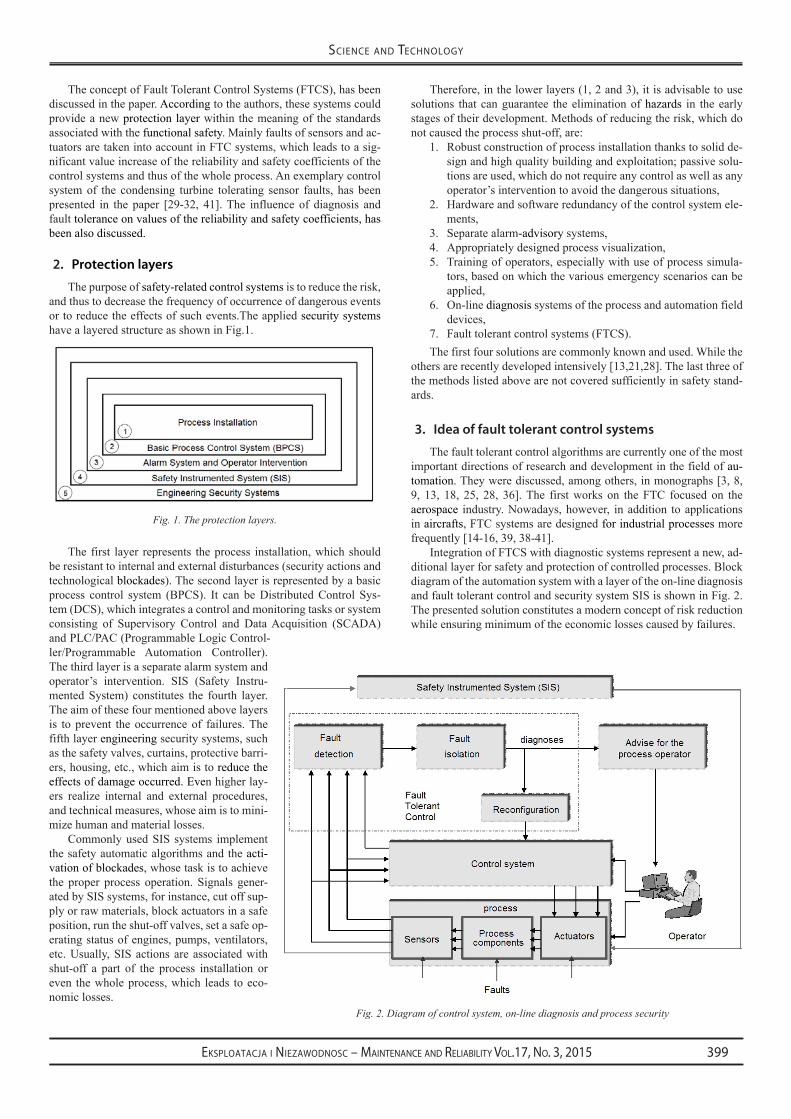
Integration of FTCS with diagnostic systems represent a new, ad-ditional layer for safety and protection of controlled processes. Block diagram of the automation system with a layer of the on-line diagnosis and fault tolerant control and security system SIS is shown in Fig. 2. The presented solution constitutes a modern concept of risk reduction while ensuring minimum of the economic losses caused by failures.
Fig. 1. The protection layers.
Fig. 2. Diagram of control system, on-line diagnosis and process security
Eksploatacja i NiEzawodNosc – MaiNtENaNcE aNd REliability Vol.17, No. 3, 2015400
sciENcE aNd tEchNology
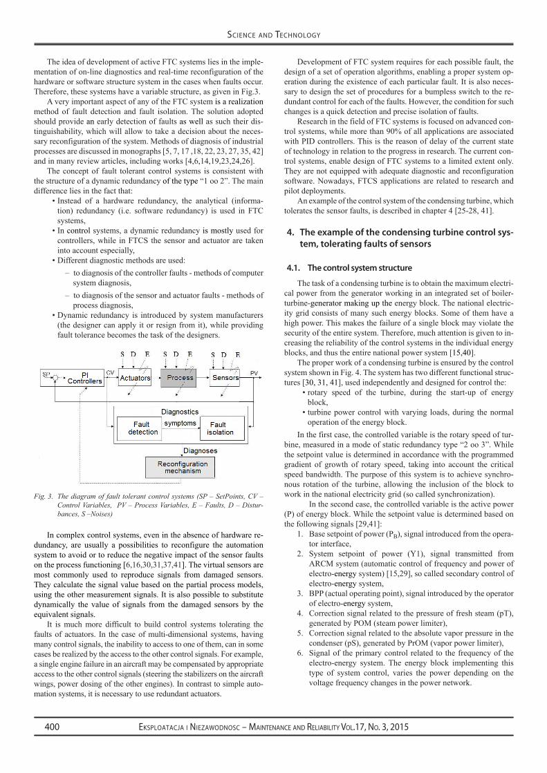
The idea of development of active FTC systems lies in the imple-mentation of on-line diagnostics and real-time reconfiguration of the hardware or software structure system in the cases when faults occur. Therefore, these systems have a variable structure, as given in Fig.3.
A very important aspect of any of the FTC system is a realization method of fault detection and fault isolation. The solution adopted should provide an early detection of faults as well as such their dis-tinguishability, which will allow to take a decision about the neces-sary reconfiguration of the system. Methods of diagnosis of industrial processes are discussed in monographs [5, 7, 17 ,18, 22, 23, 27, 35, 42] and in many review articles, including works [4,6,14,19,23,24,26].
The concept of fault tolerant control systems is consistent with the structure of a dynamic redundancy of the type “1 oo 2”. The main difference lies in the fact that:
Instead of a hardware redundancy, the analytical (informa-•tion) redundancy (i.e. software redundancy) is used in FTC systems, In • control systems, a dynamic redundancy is mostly used for controllers, while in FTCS the sensor and actuator are taken into account especially,Different diagnostic methods are used: •
to diagnosis of the controller faults - methods of computer –system diagnosis, to diagnosis of the sensor and actuator faults - methods of –process diagnosis,
Dynamic redundancy is introduced by system manufacturers •(the designer can apply it or resign from it), while providing fault tolerance becomes the task of the designers.
In complex control systems, even in the absence of hardware re-dundancy, are usually a possibilities to reconfigure the automation system to avoid or to reduce the negative impact of the sensor faults on the process functioning [6,16,30,31,37,41]. The virtual sensors are most commonly used to reproduce signals from damaged sensors. They calculate the signal value based on the partial process models, using the other measurement signals. It is also possible to substitute dynamically the value of signals from the damaged sensors by the equivalent signals.
It is much more difficult to build control systems tolerating the faults of actuators. In the case of multi-dimensional systems, having many control signals, the inability to access to one of them, can in some cases be realized by the access to the other control signals. For example, a single engine failure in an aircraft may be compensated by appropriate access to the other control signals (steering the stabilizers on the aircraft wings, power dosing of the other engines). In contrast to simple auto-mation systems, it is necessary to use redundant actuators.
Development of FTC system requires for each possible fault, the design of a set of operation algorithms, enabling a proper system op-eration during the existence of each particular fault. It is also neces-sary to design the set of procedures for a bumpless switch to the re-dundant control for each of the faults. However, the condition for such changes is a quick detection and precise isolation of faults.
Research in the field of FTC systems is focused on advanced con-trol systems, while more than 90% of all applications are associated with PID controllers. This is the reason of delay of the current state of technology in relation to the progress in research. The current con-trol systems, enable design of FTC systems to a limited extent only. They are not equipped with adequate diagnostic and reconfiguration software. Nowadays, FTCS applications are related to research and pilot deployments.
An example of the control system of the condensing turbine, which tolerates the sensor faults, is described in chapter 4 [25-28, 41].
4. The example of the condensing turbine control sys-tem, tolerating faults of sensors
4.1. The control system structure
The task of a condensing turbine is to obtain the maximum electri-cal power from the generator working in an integrated set of boiler-turbine-generator making up the energy block. The national electric-ity grid consists of many such energy blocks. Some of them have a high power. This makes the failure of a single block may violate the security of the entire system. Therefore, much attention is given to in-creasing the reliability of the control systems in the individual energy blocks, and thus the entire national power system [15,40].
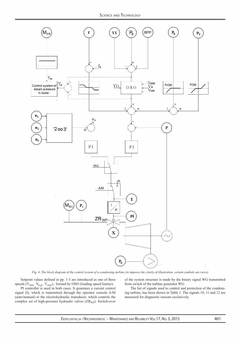
The proper work of a condensing turbine is ensured by the control system shown in Fig. 4. The system has two different functional struc-tures [30, 31, 41], used independently and designed for control the:
rotary speed of the turbine, during the start-up of energy •block,turbine power control with varying loads, during the normal •operation of the energy block.
In the first case, the controlled variable is the rotary speed of tur-bine, measured in a mode of static redundancy type “2 oo 3”. While the setpoint value is determined in accordance with the programmed gradient of growth of rotary speed, taking into account the critical speed bandwidth. The purpose of this system is to achieve synchro-nous rotation of the turbine, allowing the inclusion of the block to work in the national electricity grid (so called synchronization).
In the second case, the controlled variable is the active power (P) of energy block. While the setpoint value is determined based on the following signals [29,41]:
Base setpoint of power (P1. B), signal introduced from the opera-tor interface,System setpoint of power (Y1), signal transmitted from 2. ARCM system (automatic control of frequency and power of electro-energy system) [15,29], so called secondary control of electro-energy system,BPP (actual operating point), signal introduced by the operator 3. of electro-energy system,Correction signal related to the pressure of fresh steam (pT), 4. generated by POM (steam power limiter),Correction signal related to the absolute vapor pressure in the 5. condenser (pS), generated by PrOM (vapor power limiter),Signal of the primary control related to the frequency of the 6. electro-energy system. The energy block implementing this type of system control, varies the power depending on the voltage frequency changes in the power network.
Fig. 3. The diagram of fault tolerant control systems (SP – SetPoints, CV – Control Variables, PV – Process Variables, E – Faults, D – Distur-bances, S –Noises)
Eksploatacja i NiEzawodNosc – MaiNtENaNcE aNd REliability Vol.17, No. 3, 2015 401
sciENcE aNd tEchNology
Setpoint values defined in pp. 1-3 are introduced as one of three speeds (Vmin, Vavg, Vmax), formed by OSO (loading speed limiter).
PI controller is used in both cases. It generates a current control signal (I), which is transmitted through the operator console A/M (auto/manual) to the electrohydraulic transducer, which controls the complex set of high-pressure hydraulic valves (ZRWP). Switch-over
of the system structure is made by the binary signal WG transmitted from switch of the turbine generator WG.
The list of signals used to control and protection of the condens-ing turbine, has been shown in Table 1. The signals 10, 11 and 12 are measured for diagnostic reasons exclusively.
Fig. 4. The block diagram of the control system of a condensing turbine (to improve the clarity of illustration, certain symbols are twice)

Eksploatacja i NiEzawodNosc – MaiNtENaNcE aNd REliability Vol.17, No. 3, 2015402
sciENcE aNd tEchNology
4.2. Fault Detection and Fault Isolation
There are two phases distinguish during a process diagnosis (Fig. 3): fault detection (FD) and fault isolation (FI). For FD pur-poses, the method based on relationships between values of process variables, is used in the considered example. On the basis of these re-lationships, the partial process models are designed, which constitute an information redundancy. The goal is to find models with possible simple structures which satisfactorily meet established requirements. The search for simple structures arises from the need to minimize the calculation time of model output. Adopted relationships should also take into account the dynamics of the value changes of the model parameters. Taking into account the above aspects, the following rela-tions were distinguished for the modeling purposes:
1 1( , )tDTt tP f M P−
Λ
−= (1)
11( , )t tDT DTtM f X M −
Λ
−= (2)
( )ip f IΛ
= (3)
( , )TI f P pΛ= (4)
Symbols used in the formulas (1, 2, 3, 4), have been defined in Table 1.
One way to design models for diagnostic purposes is to use the idea of neural fuzzy systems, Takagi-Sugeno-Kang (NFS-TSK). This mathematical apparatus can be used for reliability analysis [10] or modeling for the purpose of analytical redundancy [10, 38].
Neural fuzzy systems are a combination of fuzzy modeling and the structure of artificial neural networks. The construction of NFS model begins with choosing the input and output variables. When cre-ating a fuzzy neural model, expert knowledge is used to determine the number of fuzzy sets for each input and distribution of these fuzzy sets. The value ranges of the model inputs are determined on the ba-sis of measured process data archived by the SCADA or DCS. The number of fuzzy sets determines unambiguously the number of rules. The type of membership function (trapezoidal, triangular, Gaussian)
should also be specified. Finally, the model weights are cal-culated according to the selected neural network learning al-gorithm. The designed model should provide sufficient mod-eling accuracy for diagnostic purposes.
There are known algorithms of model identification, with the use of genetic optimization, in which the selection of TSK model structure and parameters is fully automatically imple-mented [38].
NFS model created in accordance with the formula (1), is shown in Fig. 5. On the other hand, Fig. 6 presents the trends of the following variables: MDT - the mass flow of the steam, P - the active power of the generator, P^ - output from the model represented by the formula (1) with specified input signals, r1- residuum of the model, understood as the differ-ence r1=P-P^. The residuum chart confirms that model suf-ficiently reflects reality for diagnostic purposes.
The presented relationships were also tested in terms of their sensitivity to detect of sensor faults. The sensor faults
can be classified into two basic types: catastrophic faults and para-metric faults. The catastrophic faults cause a sudden change of the residuum value. Such a change implies the need to make immedi-ate appropriate safety action. In contrast, the parametric faults are as-sociated with the aging of the components. They are manifested in the form of accumulation of the residuum value. Measures of these changes are mean or variance of the residuum value. On the basis of these parameters a decisions about the need to change the operation manner of the control system may be undertaken.
In order to verify the sensitivity of the model to detect disturbanc-es in the measurement circuit of the active power of the generator, a special fault was simulated. The fault consisting in setting a fixed value of the signal, at a certain moment, for a certain time. Simulation effects of this disturbance, are shown in Fig. 7. The trends demon-strate that the residuum is sensitive to the simulated fault of the active power sensor. The average values of residuals in the sliding window, are used for detecting of faults of measuring circuits. This constitutes the simplest way of filtration.
The next step in the diagnostic process is the isolation of the dam-aged measuring circuit. There are many methods of fault isolation. One of the ways is to present relationship: faults-symptoms in the shape of a binary diagnostic matrix. The elements of the matrix take
Table 1. List of signals used in the control system of the condensing turbine.
No. Analog signal Symbol Units
1 active power of generator P Mw
2 pressure of fresh steam pT MPa
3 absolute vapor pressure in condenser (vacuum) pS kPa (%)
4 mass flow of steam MDT t/h
5 base setpoint of power PB Mw
6 system setpoint of power y1 Mw
7 actual operating point BPP Mw
8 frequency of electric current f Hz
9 rotational speed of turbine n 1/min
10 control signal, current signal i mA
11 oil pressure pulse pi MPa
12 opening degree of control valves X %
Fig. 5. The structure of the neural fuzzy model created in accordance with formula (1)

Eksploatacja i NiEzawodNosc – MaiNtENaNcE aNd REliability Vol.17, No. 3, 2015 403
sciENcE aNd tEchNology
a value of 0 or 1, wherein a value of 1 indicates that the residuum is sensitive to a given fault. The fault occurrence causes that the re-siduum deviates from zero. The exceeding of the defined threshold, is interpreted as a symptom occurrence.
During the design process, one should identify the sensitivity of all the residuals for each fault. The binary diagnostic matrix prepared for the analyzed control system is shown in Table 2.
Detection of sensor fault must result in the reconfiguration of the control system structure or changing the control algorithm. The
condensing turbine control system plays a very responsible role in the national power system, therefore immobilizing of the turbine due to fault of the measuring circuits of process variables is not allowed [31, 32].
4.3. Reconfiguration after the occurrence of faults
When starting to design the control system tolerating faults of measuring circuits, it is to specify a set of possible states of the opera-tion (F) of the system, in the case of particular faults:
{ }: 1,2...,mF f m M= = (5)
Brief description of the possible change of the system operation when occur the faults defined in Table. 1, has been presented in Ta-ble 3.
One of the most important signals introduced to the control sys-tem for the purpose of control and safety, is the steam pressure pT. In control systems with a leading turbine, checking the steam pressure is intended to protect the energetic block against the unacceptable power fluctuations. The power generated by the energetic block should be adapted to the current possibilities of water, air and fuel supply in-stallations. Therefore, in case of fault detection of the steam pressure measuring circuit, one should change the operation manner of the con-
Fig. 6. The modeling results for the data not covered by a training data set. Model was created on basis of formula (1)
Fig. 7. Simulation of a disturbance in the measurement circuit of the active power (P). Symbols used: P - active power generator, P^ - calculated output of the model based on formula (1), P* - fault simulation of the power measurement circuit, MDT- steam mass flow, r1 - model residuum
Table 2. The binary diagnostic matrix.
MDT P pT pi i
1r P PΛ
= − 1 1 0 0 0
2 DT DTr M MΛ
= −1 0 0 0 0
3 i ir p pΛ
= − 0 0 0 1 1
4r I IΛ
= − 0 1 1 0 1
Table 3. System reconfiguration after the occurrence of possible faults of mea-suring circuits
State Fault of measuring circuit
Possible change of operation when fault occur
F1 Active power (P) pro-duced by generator
Use of virtual power sensor or switching to manual control of turbine valves from operator console.
F2 Pressure of fresh steam (pT)
Disconnection of the primary control. Blockade of intervention power (block-ade of y1i signal). Turning off the steam power limiter (PoM). setting the minimum speed in the load-ing speed limiter (oso).
F3 Absolute vapor pres-sure in condenser (vacuum) (pS)
Turning off the vacuum power limiter (ProM). Blockade of intervention power (blockade of y1i signal).
F4 Mass flow of steam (MDT)
Disconnection of the signal ym coupling of the boiler control system with the turbine control system.
F5 system setpoint of power (ARcM-y1)
Disconnection of the signal y1from the secondary control (system power set-point).
F6 Actual operating point (BPP)
changing the setpoint from BPP on PB - the base setpoint of power (on the operator panel).
F7 Frequency of the electric current (f )
Use of turbine rotary speed instead of a current frequency.
F8 The rotational speed of the turbine (n)
Rejection of measurements from a faulty sensor and work with the other two.
F9 Measurement of the control signal (i)
Reconfiguration of diagnostic system which supports the control system.
The oil pressure pulse (pi)
The opening degree of control valves (X)

Eksploatacja i NiEzawodNosc – MaiNtENaNcE aNd REliability Vol.17, No. 3, 2015404
sciENcE aNd tEchNology
trol system so that the fault does not have a negative impact on the whole energetic block. For this purpose, it is necessary to reconfigure the system, consisting of the following actions:
Disconnection of the primary con-1) trol system, because it is relatively fast and can have a negative impact on the operation of the energetic block, in the absence of appropri-ate value of the steam pressure,Blockade of the binary signal Y1i 2) of the intervention power,Turning off the steam power lim-3) iter (POM). The characteristics of the output of this programming block is depending on the meas-ured value of the steam pressure. Incorrectly measured pressure value may send false signals to the power setpoint for the whole ener-getic block,Setting of minimum speed V4) min [MW/min] in OSO (loading speed limiter).
With the above assumptions, the block can operate to a limited extent, even with the remote signals, as shown in Fig.8. Additional protective signals Ym and Yp, coupling the power control system with a control steam pressure in the boiler, which ensure to get the adequate power in the system with the leading turbine. In this kind of systems the turbine power control plays in the energetic block the primary role. In contrast, the boiler steam pressure control is subordinated. One should stress, however a general rule, that it is better to switch off the remote setpoint source, than defending the remote control mode at all costs. This could result in disconnection of the energetic block from the national electro-energy system.
5. Influence of diagnostics and fault tolerance on the coeffi-cients of system reliability and system safety
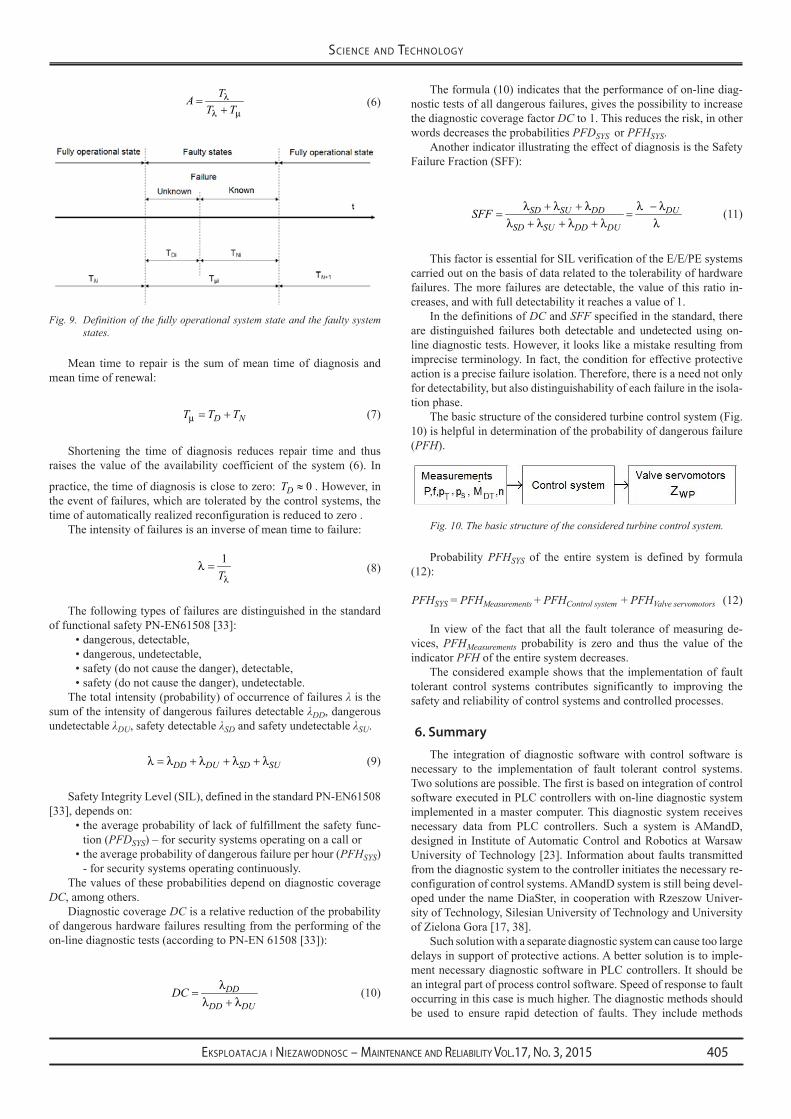
A positive influence of fault tolerance and diagnosis carried out in real time on the reliability and security of the system can be demonstrated by analyzing the co-efficients characterizing these properties. Definition of the fully operational system state and the faulty system states (e.g. F1-F9 states shown in Table 3), is given in Fig. 9. The characteristic time intervals have the following meaning:
Mean time to failure (• MTTF) - Tλ , Mean time to repair (• MTTR), i.e. the average time interval from
the failure occurring till the repair of a faulty device - Tµ ,Mean time between failures (• MTBF), i.e. MTBF MTTF MTTR= + ,
Mean time of diagnosis• - DT Mean time of renewal, i.e. replacing the defective device to the •efficient one together with the restoration of the system after
repair/replacement - NT .In case of the repairable systems, such as FTCS, the system avail-
ability coefficient, is widely used as the reliability indicator [44]. It is defined by the formula:
Fig. 8. Block diagram of the turbine control system shown in Fig. 3, after the reconfiguration made after fault detection of the measuring circuit pT
Eksploatacja i NiEzawodNosc – MaiNtENaNcE aNd REliability Vol.17, No. 3, 2015 405
sciENcE aNd tEchNology
TA
T Tλ
λ µ=
+ (6)
Mean time to repair is the sum of mean time of diagnosis and mean time of renewal:
D NT T Tµ = + (7)
Shortening the time of diagnosis reduces repair time and thus raises the value of the availability coefficient of the system (6). In
practice, the time of diagnosis is close to zero: 0DT ≈ . However, in the event of failures, which are tolerated by the control systems, the time of automatically realized reconfiguration is reduced to zero .
The intensity of failures is an inverse of mean time to failure:
1
Tλλ = (8)
The following types of failures are distinguished in the standard of functional safety PN-EN61508 [33]:
dangerous, detectable,•dangerous, undetectable,•safety (do not cause the danger), detectable,•safety (do not cause the danger), undetectable.•
The total intensity (probability) of occurrence of failures λ is the sum of the intensity of dangerous failures detectable λDD, dangerous undetectable λDU, safety detectable λSD and safety undetectable λSU.
DD DU SD SUλ λ λ λ λ= + + + (9)
Safety Integrity Level (SIL), defined in the standard PN-EN61508 [33], depends on:
the average probability of lack of fulfillment the safety func-•tion (PFDSYS) – for security systems operating on a call or the average probability of dangerous failure per hour (• PFHSYS) - for security systems operating continuously.
The values of these probabilities depend on diagnostic coverage DC, among others.
Diagnostic coverage DC is a relative reduction of the probability of dangerous hardware failures resulting from the performing of the on-line diagnostic tests (according to PN-EN 61508 [33]):
DD
DD DUDC λ
λ λ=
+ (10)
The formula (10) indicates that the performance of on-line diag-nostic tests of all dangerous failures, gives the possibility to increase the diagnostic coverage factor DC to 1. This reduces the risk, in other words decreases the probabilities PFDSYS or PFHSYS.
Another indicator illustrating the effect of diagnosis is the Safety Failure Fraction (SFF):
SD SU DD DU
SD SU DD DUSFF λ λ λ λ λ
λ λ λ λ λ+ + −
= =+ + +
(11)
This factor is essential for SIL verification of the E/E/PE systems carried out on the basis of data related to the tolerability of hardware failures. The more failures are detectable, the value of this ratio in-creases, and with full detectability it reaches a value of 1.
In the definitions of DC and SFF specified in the standard, there are distinguished failures both detectable and undetected using on-line diagnostic tests. However, it looks like a mistake resulting from imprecise terminology. In fact, the condition for effective protective action is a precise failure isolation. Therefore, there is a need not only for detectability, but also distinguishability of each failure in the isola-tion phase.
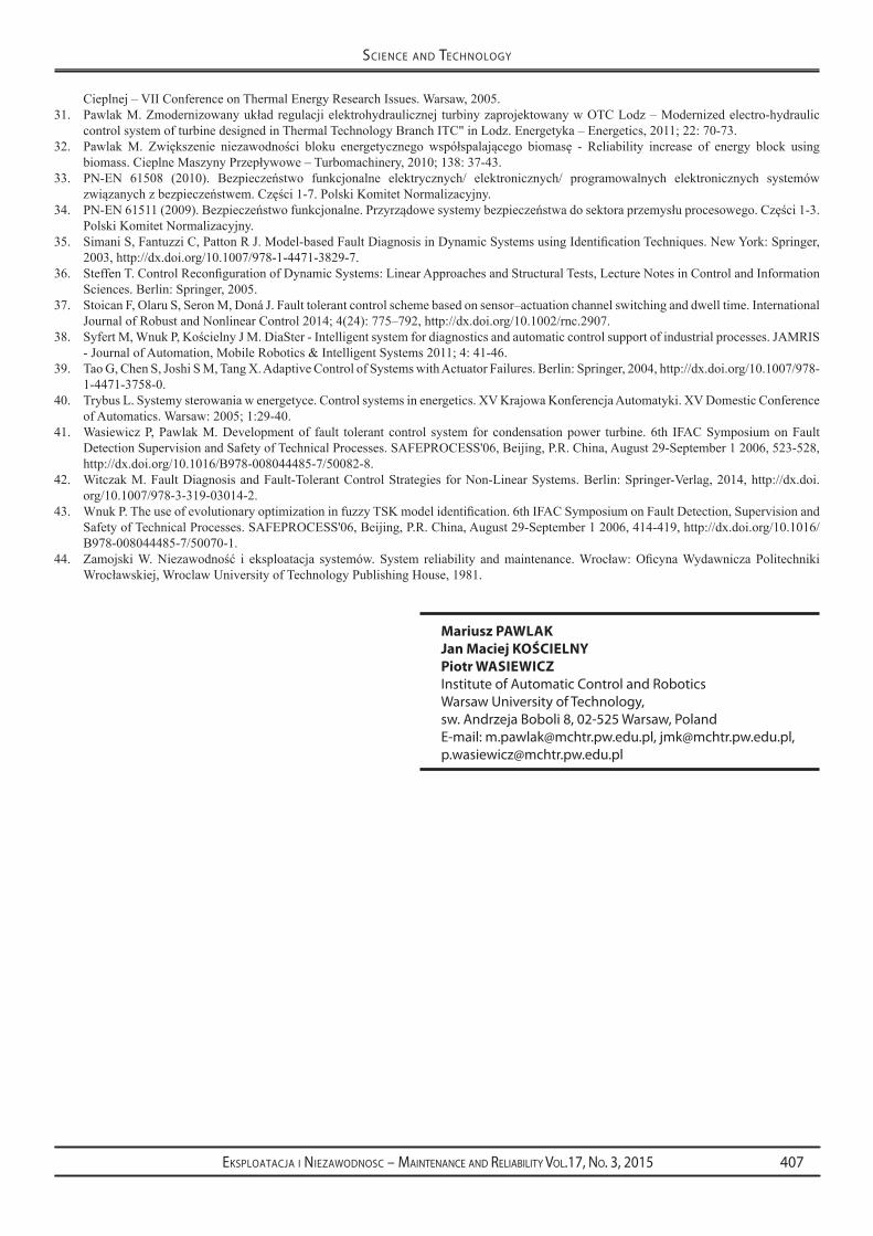
The basic structure of the considered turbine control system (Fig. 10) is helpful in determination of the probability of dangerous failure (PFH).
Probability PFHSYS of the entire system is defined by formula (12):
PFHSYS = PFHMeasurements + PFHControl system + PFHValve servomotors (12)
In view of the fact that all the fault tolerance of measuring de-vices, PFHMeasurements probability is zero and thus the value of the indicator PFH of the entire system decreases.
The considered example shows that the implementation of fault tolerant control systems contributes significantly to improving the safety and reliability of control systems and controlled processes.
6. Summary
The integration of diagnostic software with control software is necessary to the implementation of fault tolerant control systems. Two solutions are possible. The first is based on integration of control software executed in PLC controllers with on-line diagnostic system implemented in a master computer. This diagnostic system receives necessary data from PLC controllers. Such a system is AMandD, designed in Institute of Automatic Control and Robotics at Warsaw University of Technology [23]. Information about faults transmitted from the diagnostic system to the controller initiates the necessary re-configuration of control systems. AMandD system is still being devel-oped under the name DiaSter, in cooperation with Rzeszow Univer-sity of Technology, Silesian University of Technology and University of Zielona Gora [17, 38].
Such solution with a separate diagnostic system can cause too large delays in support of protective actions. A better solution is to imple-ment necessary diagnostic software in PLC controllers. It should be an integral part of process control software. Speed of response to fault occurring in this case is much higher. The diagnostic methods should be used to ensure rapid detection of faults. They include methods
Fig. 9. Definition of the fully operational system state and the faulty system states.
Fig. 10. The basic structure of the considered turbine control system.

Eksploatacja i NiEzawodNosc – MaiNtENaNcE aNd REliability Vol.17, No. 3, 2015406
sciENcE aNd tEchNology
based on models of objects. Such a solution has been implemented in the condensing turbine control system, in one of the national energetic blocks [29-32, 41].
It can be expected that in the nearest future, the rapid development of control systems equipped with software for process diagnosis and fault tolerance will take place. Also the number of industrial applica-tions will grow in this field. Of course, such systems before deploy-ing them to the industry, require full verification and validation of
hardware and software, in accordance with the requirements of the relevant functional safety standards (PN-EN 61508 i PN-EN 61511 lub PN-EN 62061), in the overall functional safety management in the life cycle [20, 21]. A certain barrier for industrial applications is lack of sufficient number of appropriate specialists. However, now in many technical universities these issues are included in the curricula and young engineers will be prepared to implement innovative control systems.
References
1. http://www.sache.org/beacon/files/2009/09/pl/read/2009-09-Beacon-Polish%20-s.pdf2. http://archiwum.ciop.pl/18388.html3. Blanke M, Kinnaert M, Lunze J, Staroswiecki M. Diagnosis and Fault-Tolerant Control. Berlin Springer-Verlag, 2004.4. Calado J M F, Korbicz J, Patan K, Patton R J, Sáda Costa J M G. Soft computing approaches to fault diagnosis for dynamic systems.
European Journal of Control 2001; 7(2–3): 248–286, http://dx.doi.org/10.3166/ejc.7.248-286.5. Chiang L H, Russell E L, Braatz R D. Fault Detection and Diagnosis in Industrial Systems. London: Springer, 2001, http://dx.doi.
org/10.1007/978-1-4471-0347-9.6. Frank P M. Fault diagnosis in dynamic systems using analytical and knowledge-based redundancy. Automatica 1990; 26: 459-474, http://
dx.doi.org/10.1016/0005-1098(90)90018-D.7. Gertler J. Fault Detection and Diagnosis in Engineering Systems, New York - Basel - Hong Kong: Marcel Dekker. Inc., 1998.8. HajiyevC,CaliskanF.FaultDiagnosisandReconfigurationinFlightControlSystems.London:KluwerAcademicPublishers,2003,http://
dx.doi.org/10.1007/978-1-4419-9166-9.9. HéctorB,FabiánG.ReconfigurableDistributedControl.London:Springer,2005.10. Huang H Z. Structural reliability analysis using fuzzy sets theory. Eksploatacja i Niezawodnosc – Maintenance and Reliability 2012; 14(4):
284–294.11. IEC 61508 (2010). Functional safety of electrical/electronic/programmable electronic safety – related systems. Parts 1-7. International
Electrotechnical Commission (IEC), Geneva.12. IEC 62061 (2005). Safety of machinery – Functional safety of safety-related electrical/electronic and programmable electronic control
systems (E/E/PE). International Electrotechnical Commission (IEC), Geneva.13. Isermann I. Fault-Diagnosis Systems: An Introduction from Fault Detection to Fault Tolerance. Berlin: Springer, 2005.14. Isermann R, Ballé P. Trends in the application of model-based fault detection and diagnosis of technical process. Control Engineering
Practice 1997; 5(5): 709-719, http://dx.doi.org/10.1016/S0967-0661(97)00053-1.15. JormakkaH,KoponenP,PentikainenH,Bartoszewicz-BurczyH.Onmanagingphysicalandcyberthreatstoenergysystemsidentification
and countermeasure requirements. Eksploatacja i Niezawodnosc – Maintenance and Reliability 2010; 3: 27-33.16. Kamal E, Aitouche A, Ghorbani R, Bayart M. Fuzzy Scheduler Fault-Tolerant Control for Wind Energy Conversion Systems. Control
Systems Technology, IEEE Transactions 2014; 1(22):119 – 131, http://dx.doi.org/10.1109/TCST.2013.2246162.17. KorbiczJ,KościelnyJM.Modeling,DiagnosticsandProcessControl.ImplementationintheDiaSterSystem.Springer,2010.18. KorbiczJ,KościelnyJM,KowalczukZ,CholewaW,etal.FaultDiagnosis:Models,artificialintelligencemethods,applications.Berlin:
Springer, 2004, http://dx.doi.org/10.1007/978-3-642-18615-8.19. Korbicz J. Robust fault detection using analytical and soft computing methods. Bulletin of the Polish Academy Sciences. Technical Sciences
2006, 54(1):75-88.20. Kosmowski K. Layer of protection analysis in the context of functional safety management. 10th Conference Diagnostics of Processes and
Systems.Zamość:2011;1:371-37821. KosmowskiK,ŚliwińskiM.Odlipca2015r.zmianywnormiePNEN61511.IVForumBezpieczeństwaFunkcjonalnego,UrządDozoru
Technicznego,OżarówMazowiecki,26-27lutego2015.22. Kościelny JM.Diagnostykazautomatyzowanychprocesówprzemysłowych–Diagnosisof automated industrialprocesses.Akademicka
OficynaWydawniczaExit–AcademicPublishingHouseExit,Warsaw,2001.23. Kościelny JM,SyfertM,WnukP.Advancedmonitoring and diagnostic system 'AMandD'. 6th IFACSymposiumonFaultDetection,
SupervisionandSafetyofTechnicalProcesses.SAFEPROCESS'06,Beijing,P.R.China,August29-September12006,635-640,http://dx.doi.org/10.1016/B978-008044485-7/50107-X.
24. Leonhardt S, Ayoubi M. Methods of fault diagnosis. Control Engineering Practice 1997; 5(5): 683-692, http://dx.doi.org/10.1016/S0967-0661(97)00050-6.
25. Mahmoud M, Jiang J, Zhang Y M. Active Fault Tolerant Control Systems. Stochastic Analysis and Synthesis. Lecture Notes in Control and Information Sciences. Berlin: Springer, 2003.
26. PattonRJ,Lopez-ToribioCJ,UppalFJ.Artificialintelligenceapproachestofaultdiagnosisfordynamicsystems.InternationalJournalofApplied Mathematics and Computer Science 1999; 9(3): 471-518.
27. Patton R J, Frank P, Clark R. Issues of fault diagnosis for dynamic systems. Berlin: Springer, 2000, http://dx.doi.org/10.1007/978-1-4471-3644-6.
28. Patton R, Montander S. Active fault tolerant control for nonlinear systems with simultaneous actuator and sensor faults. International Journal of Control, Automation and Systems 2013; 6(11): 1149-1161.
29. Pawlak M, Karczewski J. New Structure of Governor Electrohydraulic Power which meets the Requirements of the Implemented LFC-System. ActaEnergetica 2014; 1(18): 126-135.
30. PawlakM,KarczewskiJ.StrukturaUARturbinykondensacyjnejbiorącejudziałwregulacjisystemuelektroenergetycznego–Structureof control system of condensation turbine taking part in control of electroenergy system. VII Konferencja Problemy Badawcze Energetyki
Eksploatacja i NiEzawodNosc – MaiNtENaNcE aNd REliability Vol.17, No. 3, 2015 407
sciENcE aNd tEchNology
Cieplnej – VII Conference on Thermal Energy Research Issues. Warsaw, 2005.31. PawlakM.Zmodernizowanyukładregulacjielektrohydraulicznej turbinyzaprojektowanywOTCLodz–Modernizedelectro-hydraulic
control system of turbine designed in Thermal Technology Branch ITC" in Lodz. Energetyka – Energetics, 2011; 22: 70-73.32. PawlakM. Zwiększenie niezawodności bloku energetycznego współspalającego biomasę - Reliability increase of energy block using
biomass.CieplneMaszynyPrzepływowe–Turbomachinery,2010;138:37-43.33. PN-EN 61508 (2010). Bezpieczeństwo funkcjonalne elektrycznych/ elektronicznych/ programowalnych elektronicznych systemów
związanychzbezpieczeństwem.Części1-7.PolskiKomitetNormalizacyjny.34. PN-EN61511(2009).Bezpieczeństwofunkcjonalne.Przyrządowesystemybezpieczeństwadosektoraprzemysłuprocesowego.Części1-3.
Polski Komitet Normalizacyjny.35. SimaniS,FantuzziC,PattonRJ.Model-basedFaultDiagnosisinDynamicSystemsusingIdentificationTechniques.NewYork:Springer,
2003, http://dx.doi.org/10.1007/978-1-4471-3829-7.36. SteffenT.ControlReconfigurationofDynamicSystems:LinearApproachesandStructuralTests,LectureNotesinControlandInformation
Sciences. Berlin: Springer, 2005.37. Stoican F, Olaru S, Seron M, Doná J. Fault tolerant control scheme based on sensor–actuation channel switching and dwell time. International
Journal of Robust and Nonlinear Control 2014; 4(24): 775–792, http://dx.doi.org/10.1002/rnc.2907.38. SyfertM,WnukP,KościelnyJM.DiaSter-Intelligentsystemfordiagnosticsandautomaticcontrolsupportofindustrialprocesses.JAMRIS
- Journal of Automation, Mobile Robotics & Intelligent Systems 2011; 4: 41-46.39. Tao G, Chen S, Joshi S M, Tang X. Adaptive Control of Systems with Actuator Failures. Berlin: Springer, 2004, http://dx.doi.org/10.1007/978-
1-4471-3758-0.40. Trybus L. Systemy sterowania w energetyce. Control systems in energetics. XV Krajowa Konferencja Automatyki. XV Domestic Conference
of Automatics. Warsaw: 2005; 1:29-40.41. Wasiewicz P, Pawlak M. Development of fault tolerant control system for condensation power turbine. 6th IFAC Symposium on Fault
DetectionSupervisionandSafetyofTechnicalProcesses.SAFEPROCESS'06,Beijing,P.R.China,August29-September12006,523-528,http://dx.doi.org/10.1016/B978-008044485-7/50082-8.
42. Witczak M. Fault Diagnosis and Fault-Tolerant Control Strategies for Non-Linear Systems. Berlin: Springer-Verlag, 2014, http://dx.doi.org/10.1007/978-3-319-03014-2.
43. WnukP.TheuseofevolutionaryoptimizationinfuzzyTSKmodelidentification.6thIFACSymposiumonFaultDetection,SupervisionandSafetyofTechnicalProcesses.SAFEPROCESS'06,Beijing,P.R.China,August29-September12006,414-419,http://dx.doi.org/10.1016/B978-008044485-7/50070-1.
44. ZamojskiW.Niezawodność i eksploatacja systemów.System reliability andmaintenance.Wrocław:OficynaWydawniczaPolitechnikiWrocławskiej,WroclawUniversityofTechnologyPublishingHouse,1981.
Mariusz pawlakjan Maciej kościelnypiotr wasiewiczinstitute of Automatic control and Roboticswarsaw University of Technology, sw. Andrzeja Boboli 8, 02-525 warsaw, Polande-mail: [email protected], [email protected], [email protected]