MODELING OF THE GRAIN STRUCTURE FORMATION … · For the modeling the ProCAST R ... transparent...
6
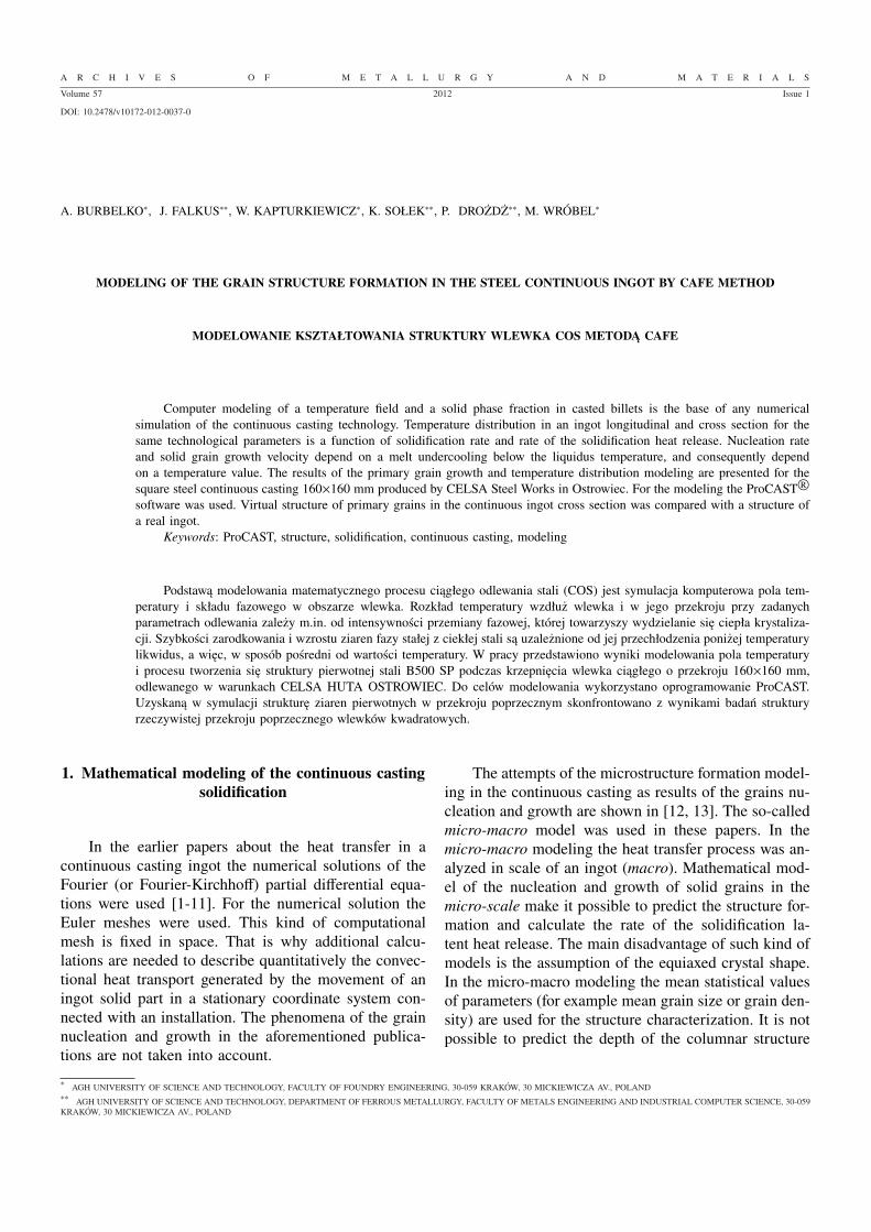
A R C H I V E S O F M E T A L L U R G Y A N D M A T E R I A L S Volume 57 2012 Issue 1 DOI: 10.2478/v10172-012-0037-0 A. BURBELKO * , J. FALKUS ** , W. KAPTURKIEWICZ * , K. SOLEK ** , P. DROŻDŻ ** , M. WRÓBEL * MODELING OF THE GRAIN STRUCTURE FORMATION IN THE STEEL CONTINUOUS INGOT BY CAFE METHOD MODELOWANIE KSZTALTOWANIA STRUKTURY WLEWKA COS METODĄ CAFE Computer modeling of a temperature field and a solid phase fraction in casted billets is the base of any numerical simulation of the continuous casting technology. Temperature distribution in an ingot longitudinal and cross section for the same technological parameters is a function of solidification rate and rate of the solidification heat release. Nucleation rate and solid grain growth velocity depend on a melt undercooling below the liquidus temperature, and consequently depend on a temperature value. The results of the primary grain growth and temperature distribution modeling are presented for the square steel continuous casting 160×160 mm produced by CELSA Steel Works in Ostrowiec. For the modeling the ProCAST R software was used. Virtual structure of primary grains in the continuous ingot cross section was compared with a structure of a real ingot. Keywords: ProCAST, structure, solidification, continuous casting, modeling Podstawą modelowania matematycznego procesu ciąglego odlewania stali (COS) jest symulacja komputerowa pola tem- peratury i skladu fazowego w obszarze wlewka. Rozklad temperatury wzdluż wlewka i w jego przekroju przy zadanych parametrach odlewania zależy m.in. od intensywności przemiany fazowej, której towarzyszy wydzielanie się ciepla krystaliza- cji. Szybkości zarodkowania i wzrostu ziaren fazy stalej z cieklej stali są uzależnione od jej przechlodzenia poniżej temperatury likwidus, a więc, w sposób pośredni od wartości temperatury. W pracy przedstawiono wyniki modelowania pola temperatury i procesu tworzenia się struktury pierwotnej stali B500 SP podczas krzepnięcia wlewka ciąglego o przekroju 160×160 mm, odlewanego w warunkach CELSA HUTA OSTROWIEC. Do celów modelowania wykorzystano oprogramowanie ProCAST. Uzyskaną w symulacji strukturę ziaren pierwotnych w przekroju poprzecznym skonfrontowano z wynikami badań struktury rzeczywistej przekroju poprzecznego wlewków kwadratowych. 1. Mathematical modeling of the continuous casting solidification In the earlier papers about the heat transfer in a continuous casting ingot the numerical solutions of the Fourier (or Fourier-Kirchhoff) partial differential equa- tions were used [1-11]. For the numerical solution the Euler meshes were used. This kind of computational mesh is fixed in space. That is why additional calcu- lations are needed to describe quantitatively the convec- tional heat transport generated by the movement of an ingot solid part in a stationary coordinate system con- nected with an installation. The phenomena of the grain nucleation and growth in the aforementioned publica- tions are not taken into account. The attempts of the microstructure formation model- ing in the continuous casting as results of the grains nu- cleation and growth are shown in [12, 13]. The so-called micro-macro model was used in these papers. In the micro-macro modeling the heat transfer process was an- alyzed in scale of an ingot (macro). Mathematical mod- el of the nucleation and growth of solid grains in the micro-scale make it possible to predict the structure for- mation and calculate the rate of the solidification la- tent heat release. The main disadvantage of such kind of models is the assumption of the equiaxed crystal shape. In the micro-macro modeling the mean statistical values of parameters (for example mean grain size or grain den- sity) are used for the structure characterization. It is not possible to predict the depth of the columnar structure * AGH UNIVERSITY OF SCIENCE AND TECHNOLOGY, FACULTY OF FOUNDRY ENGINEERING, 30-059 KRAKÓW, 30 MICKIEWICZA AV., POLAND ** AGH UNIVERSITY OF SCIENCE AND TECHNOLOGY, DEPARTMENT OF FERROUS METALLURGY, FACULTY OF METALS ENGINEERING AND INDUSTRIAL COMPUTER SCIENCE, 30-059 KRAKÓW, 30 MICKIEWICZA AV., POLAND
Transcript of MODELING OF THE GRAIN STRUCTURE FORMATION … · For the modeling the ProCAST R ... transparent...
A R C H I V E S O F M E T A L L U R G Y A N D M A T E R I A L S
Volume 57 2012 Issue 1
DOI: 10.2478/v10172-012-0037-0
A. BURBELKO∗, J. FALKUS∗∗, W. KAPTURKIEWICZ∗, K. SOŁEK∗∗, P. DROŻDŻ∗∗, M. WRÓBEL∗
MODELING OF THE GRAIN STRUCTURE FORMATION IN THE STEEL CONTINUOUS INGOT BY CAFE METHOD
MODELOWANIE KSZTAŁTOWANIA STRUKTURY WLEWKA COS METODĄ CAFE
Computer modeling of a temperature field and a solid phase fraction in casted billets is the base of any numericalsimulation of the continuous casting technology. Temperature distribution in an ingot longitudinal and cross section for thesame technological parameters is a function of solidification rate and rate of the solidification heat release. Nucleation rateand solid grain growth velocity depend on a melt undercooling below the liquidus temperature, and consequently dependon a temperature value. The results of the primary grain growth and temperature distribution modeling are presented for thesquare steel continuous casting 160×160 mm produced by CELSA Steel Works in Ostrowiec. For the modeling the ProCAST R©software was used. Virtual structure of primary grains in the continuous ingot cross section was compared with a structure ofa real ingot.
Keywords: ProCAST, structure, solidification, continuous casting, modeling
Podstawą modelowania matematycznego procesu ciągłego odlewania stali (COS) jest symulacja komputerowa pola tem-peratury i składu fazowego w obszarze wlewka. Rozkład temperatury wzdłuż wlewka i w jego przekroju przy zadanychparametrach odlewania zależy m.in. od intensywności przemiany fazowej, której towarzyszy wydzielanie się ciepła krystaliza-cji. Szybkości zarodkowania i wzrostu ziaren fazy stałej z ciekłej stali są uzależnione od jej przechłodzenia poniżej temperaturylikwidus, a więc, w sposób pośredni od wartości temperatury. W pracy przedstawiono wyniki modelowania pola temperaturyi procesu tworzenia się struktury pierwotnej stali B500 SP podczas krzepnięcia wlewka ciągłego o przekroju 160×160 mm,odlewanego w warunkach CELSA HUTA OSTROWIEC. Do celów modelowania wykorzystano oprogramowanie ProCAST.Uzyskaną w symulacji strukturę ziaren pierwotnych w przekroju poprzecznym skonfrontowano z wynikami badań strukturyrzeczywistej przekroju poprzecznego wlewków kwadratowych.
1. Mathematical modeling of the continuous castingsolidification
In the earlier papers about the heat transfer in acontinuous casting ingot the numerical solutions of theFourier (or Fourier-Kirchhoff) partial differential equa-tions were used [1-11]. For the numerical solution theEuler meshes were used. This kind of computationalmesh is fixed in space. That is why additional calcu-lations are needed to describe quantitatively the convec-tional heat transport generated by the movement of aningot solid part in a stationary coordinate system con-nected with an installation. The phenomena of the grainnucleation and growth in the aforementioned publica-tions are not taken into account.
The attempts of the microstructure formation model-ing in the continuous casting as results of the grains nu-cleation and growth are shown in [12, 13]. The so-calledmicro-macro model was used in these papers. In themicro-macro modeling the heat transfer process was an-alyzed in scale of an ingot (macro). Mathematical mod-el of the nucleation and growth of solid grains in themicro-scale make it possible to predict the structure for-mation and calculate the rate of the solidification la-tent heat release. The main disadvantage of such kind ofmodels is the assumption of the equiaxed crystal shape.In the micro-macro modeling the mean statistical valuesof parameters (for example mean grain size or grain den-sity) are used for the structure characterization. It is notpossible to predict the depth of the columnar structure
∗ AGH UNIVERSITY OF SCIENCE AND TECHNOLOGY, FACULTY OF FOUNDRY ENGINEERING, 30-059 KRAKÓW, 30 MICKIEWICZA AV., POLAND∗∗ AGH UNIVERSITY OF SCIENCE AND TECHNOLOGY, DEPARTMENT OF FERROUS METALLURGY, FACULTY OF METALS ENGINEERING AND INDUSTRIAL COMPUTER SCIENCE, 30-059KRAKÓW, 30 MICKIEWICZA AV., POLAND
380
zone or the relation between the longitudinal and lateralsizes of columnar grains.
Modeling of the inner structure of the dendritic grainby means of the cellular automaton (CA) method in twodimensions is presented in [14]. Modeling of the thinsegregation layer formation under a small freezing crys-tals layer in a continuous strand is shown in [15]. Un-fortunately, CA models with a cell size of order of 1 µmcannot be used for the solidification modeling on a largescale typical for industrial continuous casters.
In this paper the CAFE model [16-17] is availableas ProCAST R© software module [18] was used for thesimulation of a primary phase grains in a continuousingot. In this modeling Cellular Automata (CA) mathe-matical method is used with a grater cell size sufficientfor outer grain shape modeling. The CA modeling en-ables to take into account the stochastic bulk and surface(at the crystallizer wall) grain nucleation, as for simulat-ing individual growth of the primary phase grains. Re-sults of simulation are history of the interphase boundarymigration as well as the grain boundary position afterthe full ingot solidification. A CA simulation is con-nected with an ingot temperature field calculation. Forheat flux and temperature field modeling the Finite Ele-ment Method (FEM) was used in the ProCAST R© soft-ware. As opposed to the model [14] mentioned above,the CAFE model works with the cell size of order 0.1mm, that is why the simulation of an inner structure ofdendritic grains is not possible. On the other hand thethree-dimensional analysis of greater domains is able towork in CAFE.
The CA modeling of the microstructure formationduring the continuous ingot solidification requires themobile Lagrange’s mesh utilization connected with aningot.
2. Conditions of modeling
The calculations were performed for the square ingotof the section 160 x 160 mm produced by CELSA SteelWorks Ostrowiec (CELSA Group). The curvature of thecontinuous ingots is constant from the crystallizer up tothe straightening machine and the radius of the inneringot surface is equal to 10 m. Due to the appropriativeshape of the crystallizer’s walls the bending of an ingotin this continuous caster is not necessary.
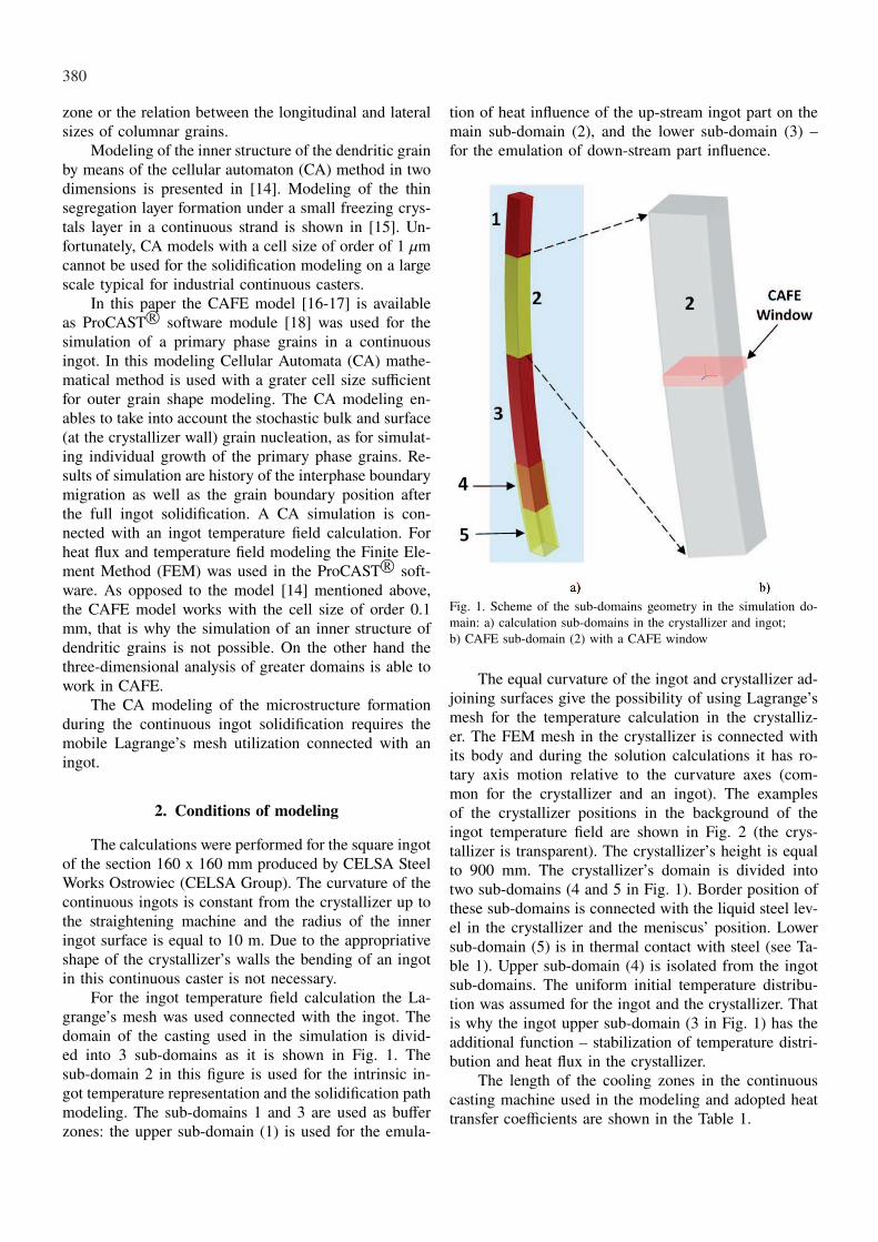
For the ingot temperature field calculation the La-grange’s mesh was used connected with the ingot. Thedomain of the casting used in the simulation is divid-ed into 3 sub-domains as it is shown in Fig. 1. Thesub-domain 2 in this figure is used for the intrinsic in-got temperature representation and the solidification pathmodeling. The sub-domains 1 and 3 are used as bufferzones: the upper sub-domain (1) is used for the emula-
tion of heat influence of the up-stream ingot part on themain sub-domain (2), and the lower sub-domain (3) –for the emulation of down-stream part influence.
Fig. 1. Scheme of the sub-domains geometry in the simulation do-main: a) calculation sub-domains in the crystallizer and ingot;b) CAFE sub-domain (2) with a CAFE window
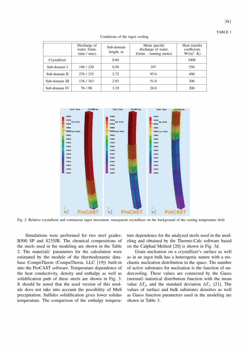
The equal curvature of the ingot and crystallizer ad-joining surfaces give the possibility of using Lagrange’smesh for the temperature calculation in the crystalliz-er. The FEM mesh in the crystallizer is connected withits body and during the solution calculations it has ro-tary axis motion relative to the curvature axes (com-mon for the crystallizer and an ingot). The examplesof the crystallizer positions in the background of theingot temperature field are shown in Fig. 2 (the crys-tallizer is transparent). The crystallizer’s height is equalto 900 mm. The crystallizer’s domain is divided intotwo sub-domains (4 and 5 in Fig. 1). Border position ofthese sub-domains is connected with the liquid steel lev-el in the crystallizer and the meniscus’ position. Lowersub-domain (5) is in thermal contact with steel (see Ta-ble 1). Upper sub-domain (4) is isolated from the ingotsub-domains. The uniform initial temperature distribu-tion was assumed for the ingot and the crystallizer. Thatis why the ingot upper sub-domain (3 in Fig. 1) has theadditional function – stabilization of temperature distri-bution and heat flux in the crystallizer.
The length of the cooling zones in the continuouscasting machine used in the modeling and adopted heattransfer coefficients are shown in the Table 1.
381
TABLE 1Conditions of the ingot cooling
Discharge ofwater, l/min.(min / max)
Sub-domainlength, m
Mean specificdischarge of water,
l/(min. · running meter)
Heat transfercoefficient,W/(m2· K)
Crystallizer 0.60 1000
Sub-domain I 196 / 220 0.50 397 550
Sub-domain II 276 / 335 2.72 95.0 400
Sub-domain III 136 / 163 2.93 51.0 300
Sub-domain IV 76 / 90 3.19 26.0 200
Fig. 2. Relative crystallizer and continuous ingot movement: transparent crystallizer on the background of the casting temperature field
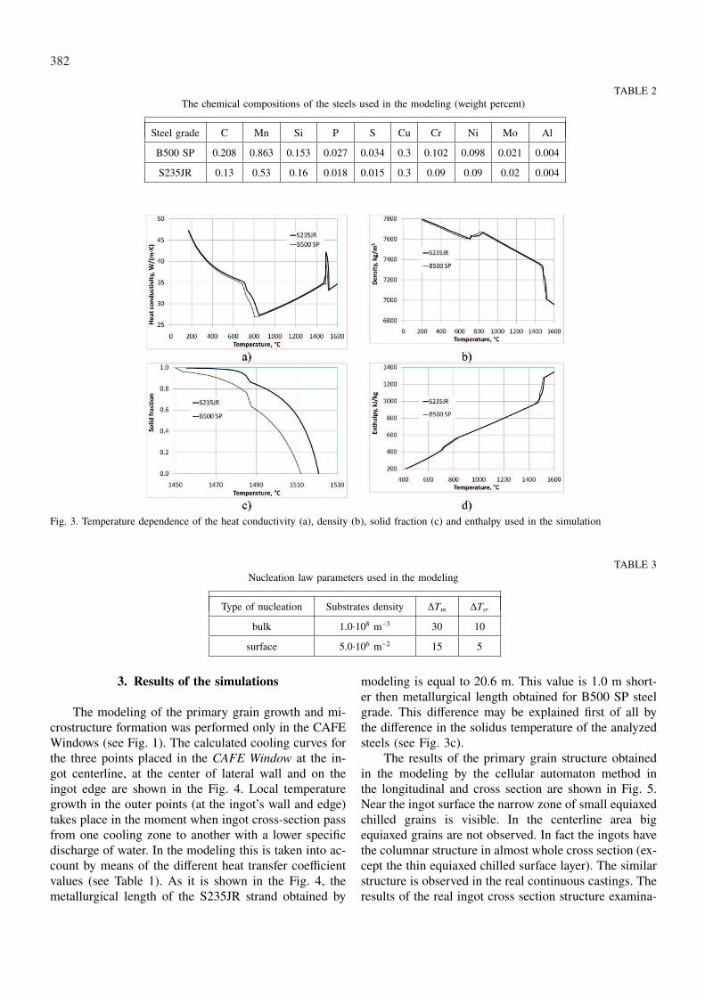
Simulations were performed for two steel grades:B500 SP and S235JR. The chemical compositions ofthe steels used in the modeling are shown in the Table2. The materials’ parameters for the calculation wereestimated by the module of the thermodynamic data-base CompuTherm (CompuTherm, LLC [19]) built-ininto the ProCAST software. Temperature dependence ofthe heat conductivity, density and enthalpy as well assolidification path of these steels are shown in Fig. 3.It should be noted that the used version of this mod-ule does not take into account the possibility of MnSprecipitation. Sulfides solidification gives lower solidustemperature. The comparison of the enthalpy tempera-
ture dependence for the analyzed steels used in the mod-eling and obtained by the Thermo-Calc software basedon the Calphad Method [20] is shown in Fig. 3d.
Grain nucleation on a crystallizer’s surface as wellas in an ingot bulk has a heterogenic nature with a sto-chastic nucleation distribution in the space. The numberof active substrates for nucleation is the function of un-dercooling. These values are connected by the Gauss(normal) statistical distribution function with the meanvalue ∆Tm and the standard deviation ∆Tσ [21]. Thevalues of surface and bulk substrates densities as wellas Gauss function parameters used in the modeling areshown in Table 3.
382
TABLE 2The chemical compositions of the steels used in the modeling (weight percent)
Steel grade C Mn Si P S Cu Cr Ni Mo Al
B500 SP 0.208 0.863 0.153 0.027 0.034 0.3 0.102 0.098 0.021 0.004
S235JR 0.13 0.53 0.16 0.018 0.015 0.3 0.09 0.09 0.02 0.004
Fig. 3. Temperature dependence of the heat conductivity (a), density (b), solid fraction (c) and enthalpy used in the simulation
TABLE 3Nucleation law parameters used in the modeling
Type of nucleation Substrates density ∆Tm ∆Tσ
bulk 1.0·108 m−3 30 10
surface 5.0·106 m−2 15 5
3. Results of the simulations
The modeling of the primary grain growth and mi-crostructure formation was performed only in the CAFEWindows (see Fig. 1). The calculated cooling curves forthe three points placed in the CAFE Window at the in-got centerline, at the center of lateral wall and on theingot edge are shown in the Fig. 4. Local temperaturegrowth in the outer points (at the ingot’s wall and edge)takes place in the moment when ingot cross-section passfrom one cooling zone to another with a lower specificdischarge of water. In the modeling this is taken into ac-count by means of the different heat transfer coefficientvalues (see Table 1). As it is shown in the Fig. 4, themetallurgical length of the S235JR strand obtained by
modeling is equal to 20.6 m. This value is 1.0 m short-er then metallurgical length obtained for B500 SP steelgrade. This difference may be explained first of all bythe difference in the solidus temperature of the analyzedsteels (see Fig. 3c).
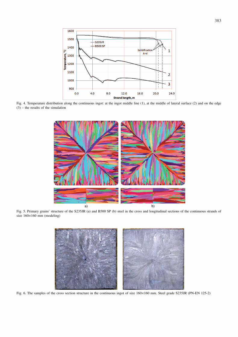
The results of the primary grain structure obtainedin the modeling by the cellular automaton method inthe longitudinal and cross section are shown in Fig. 5.Near the ingot surface the narrow zone of small equiaxedchilled grains is visible. In the centerline area bigequiaxed grains are not observed. In fact the ingots havethe columnar structure in almost whole cross section (ex-cept the thin equiaxed chilled surface layer). The similarstructure is observed in the real continuous castings. Theresults of the real ingot cross section structure examina-
383
Fig. 4. Temperature distribution along the continuous ingot: at the ingot middle line (1), at the middle of lateral surface (2) and on the edge(3) – the results of the simulation
Fig. 5. Primary grains’ structure of the S235JR (a) and B500 SP (b) steel in the cross and longitudinal sections of the continuous strands ofsize 160×160 mm (modeling)
Fig. 6. The samples of the cross section structure in the continuous ingot of size 160×160 mm. Steel grade S235JR (PN-EN 125-2)
384
tion are shown in the Fig. 6. These results are obtainedfor the quadratic continuous ingot of size 160×160 mmmanufactured by CELSA HUTA OSTROWIEC from thesteel S235JR (PN-EN 125-2).
Comparison of the Fig. 5 and 6 indicates that resultsof the continuous ingot structure modeling by means ofthe CAFE method gives a good representation of mi-crostructure of product.
4. Conclusions
The CAFE module of the ProCAST software is auseful tool for the modeling of the primary structureformation in a continuous ingot.
In the modeling of quadratic ingots of size 160×160mm the obtained structure includes the narrow zone ofsmall equiaxed chilled grains near the surface and thewide zone of columnar grains. The similar structure wasobtained in the practical examination of a commercialcontinuous ingot with the 160×160 mm cross section.The zone of equiaxed grains near the ingot middle lineis not observed as in the modeling as in the practicalexamination of these ingots.
Acknowledgements
Research work was supported by the European Regional Devel-opment Fund – the Operational Programme – Innovative Economy,as a project “New Concept for Selection of the Cooling Parametersin Continuous Casting of Steel”, POIG.01.03.01-12-009/09.
REFERENCES
[1] E. M i z i k a r, Transactions of Metallurgical Society ofAIME 11, 1474 (1967).
[2] R. T h o m s o n, E.C. E l l w o o d, The BritishFoundryman 6, 234 (1972).
[3] A. P e r k i n s, W.R. I r v i n g, Mathematical ProcessModells, Iron and Steel Institute 187-199 (1973).
[4] A. G r i l l, K. S o r i m a c h i, J.K. B r i m a c o m b e,Metall. Trans. B 7, 177 (1976).
[5] H. F i k, S. F r y d a, Archiwum Hutnictwa 3 , 433(1976).
[6] B. M o c h n a c k i, B. O r t y l, Zesz. Nauk. Politech-niki Śląskiej, Mechanika 62, 33 (1978).
[7] M. B a m b e r g e r, S. N a d i v, G.B. B a r k a y, Ironand Steel International 2, 43 (1977).
[8] M.J. M u n d i m, J.L.R. P i m e n t a, C.A.G. V a l -a d a r e s, P.F. P e r e i r a, Mathematical Analysis ofSolidification in Continuous Casting of Steel, Contin-uous Casting’85, The Institute of Metals, 501 London1985.
[9] W. K a p t u r k i e w i c z, Metalurgia i Odlewnictwo3-4, 491 (1982).
[10] B. L a l l y, L. B i e g l e r, H. H e n e i n, Metall. Trans.B 8, 761 (1990).
[11] A.J. M a n e s h A l i, Journal Materials Shaping Tech-nology 3, 179 (1990).
[12] W. K a p t u r k i e w i c z, A.A. B u r b i e l k o, Krzep-nięcie Metali i Stopów – Solidification of Metals andAlloys 18, 79 (1993).
[13] W. K a p t u r k i e w i c z, E. F r a ś, A.A. B u r -b i e l k o, The 10-th International Conference onCAD/CAM, Robotics and Factories of the Future:CARs&FOF ’94, 656 (1994).
[14] A. B u r b e l k o, Mezomodelling of solidification us-ing a cellular automaton. UWND AGH, Krakow 2004(in Polish).
[15] A.A. B u r b e l k o, I.A S e m e n o v, M. S o b e c k i,Advances in Metallurgical Processes and Materials: Pro-ceedings of the International Conference. Dnipropetro-vsk, Ukraine 2, 210 (2007).
[16] M. R a p p a z, Ch.-A. G a n d i n, Acta Metall. Mater.2, 345 (1993).
[17] Ch.-A. G a n d i n, M. R a p p a z, Acta Metall. Mater.7, 2233 (1994).
[18] Ch.-A. G a n d i n, J.L. D e s b i o l l e s, M. R a p p a z,Ph. T h e v o z, Metall. Mater. Trans. 12, 3153 (1999).
[19] http://www.computherm.com/[20] H.L. L u k a s, S.G. F i r e s, B. S u n d m a n, Compu-
tational Thermodynamics. The Calphad Method. Cam-bridge University Press. 2007.
[21] Ph. T h e v o z, J.L. D e s b i o l l e s, M. R a p p a z,Metall. Trans. A 20A , 311 (1989).
Received: 10 September 2011.