Fischer SG T 2010
60
Joints and Connections
Transcript of Fischer SG T 2010
Joints and Connections

Joints and Connections
Seth Gavin Fischer
Thesis submitted to the faculty of Virginia Polytechnic Institute and State University in partial fulfillment of the requirements for the degree of:
Master of Architecture
Hans C. Rott, Chairman
William U. Galloway
Kay F. Edge
Defense date: July 19, 2004Defense location: Blacksburg, VirginiaKeywords: Istanbul, transportation, architecture, connections
Abstract
Istanbul is a city on the water and historically has been a link between East and West. Unlike most cities, ferry boats are one of the most commonly used means of travel, along with rail and bus lines. There is a contrast between the grandeur of the historic buildings as seen from the water and the unpleasantness of disembarking from the ferry, which berths at a small shed-like structure on the edge of the water which has old tires attached to piles driven into the bank of the Golden Horn. Some distance away there is a bus terminal and train stop. The paths of travel between these are unclear and the area is chaotic. Architecture has the potential to join and connect people, physical forces, the past and present at various scales. This project seeks to accomplish this connection on a particular site by building a new structure out in the water as a central focal point and joining it to rail and bus links with a tunnel and elevated covered walkways.
Joints and ConnectionsSeth Gavin Fischer

Table of Contents
Abstract
The phenomenon of density...............................1 - Linearity...............................................................6 - Overlap................................................................7
Analysis of site forces..........................................9 - Joint between Europe and Asia.........................10 - Historical forces.................................................13 - Site Forces.........................................................15
The roof as ordering element...........................16 - Walkway.............................................................17 - Ferry Terminal...................................................18
Joining at various scales...................................23 - The border between water and land.................24 - Linking modes of transportation.......................29
- Tunnel and Walkway...........................................30 - Connecting parts of the building ......................36
Structural considerations..................................37 - Docking forces....................................................41 - Construction techniques....................................43 - The effect of currents on form ..........................44 - Further exploration of joints at a small scale...50
Conclusion..........................................................51 Bibliography and Image Credits.......................52
iii
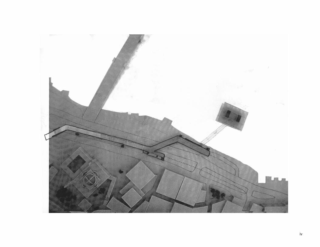
iv
The phenomenon of density
H
H H
H
H H
H H
HH
H
H
O
O
O
O
O
O
1
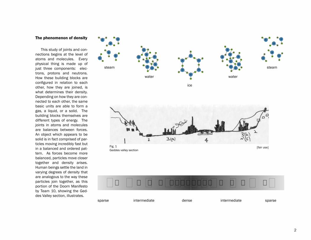
This study of joints and con-nections begins at the level of atoms and molecules. Every physical thing is made up of just three components: elec-trons, protons and neutrons. How these building blocks are configured in relation to each other, how they are joined, is what determines their density. Depending on how they are con-nected to each other, the same basic units are able to form a gas, a liquid, or a solid. The building blocks themselves are different types of energy. The joints in atoms and molecules are balances between forces. An object which appears to be solid is in fact comprised of par-ticles moving incredibly fast but in a balanced and ordered pat-tern. As forces become more balanced, particles move closer together and density arises. Human beings settle the land in varying degrees of density that are analogous to the way these particles join together, as this portion of the Doorn Manifesto by Team 10, showing the Ged-des Valley section, illustrates.
steam
water
ice
water
steam
sparse intermediate dense intermediate sparse
Geddes valley section
H
H
O
H H H
HHH
H
H
H
H
O
O
O
O
OH
H
O
H H H
HHH
H
H
H
H
O
O
O
O
OO
OO
O
O
O
O
O
H
H
H
HHH
HH
H
H
HH
H
H
H
H
O
OO
O
O
O
O
O
H
H
H
HHH
HH
H
H
HH
H
H
H
H
H
H H
H
H H
H H
HH
H
H
O
O
O
O
O
O
The phenomenon of density
2
Fig. 1 [fair use]
The Geddes Valley section is descriptive of, but does not seek to analyze, the causes leading to settle-ment patterns. One means of explaining the evolution and distribution of human settlements in an urban system is central place theory, which was created by Walter Christaller in the 1930’s. Economic forces are of primary importance in this theory, and in fact, the complications posed by topography are deliberately omitted. According to A Dictionary of Geography:
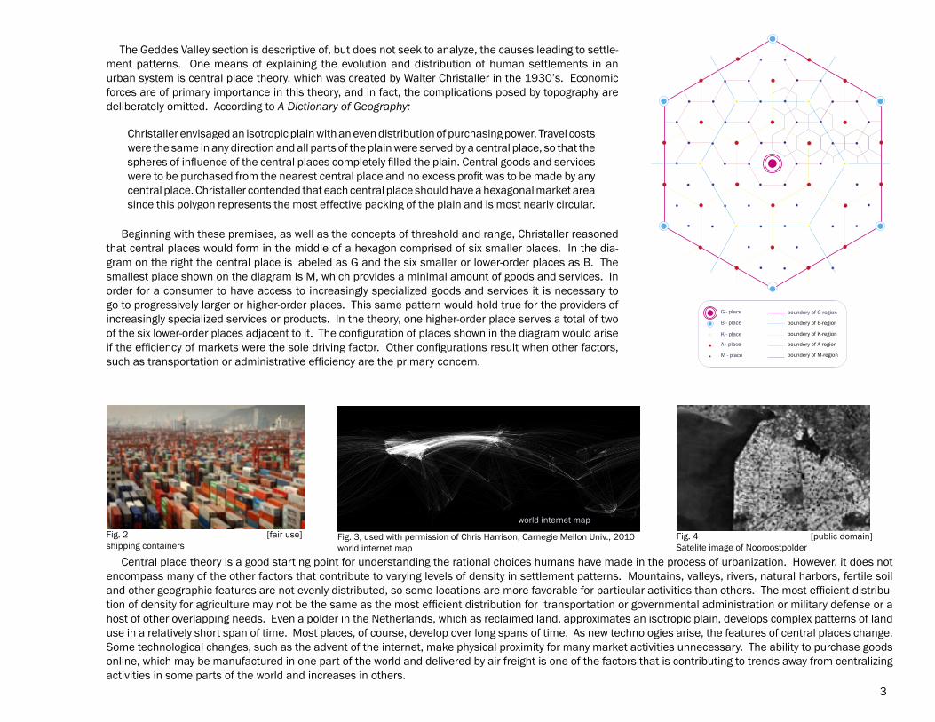
Beginning with these premises, as well as the concepts of threshold and range, Christaller reasoned that central places would form in the middle of a hexagon comprised of six smaller places. In the dia-gram on the right the central place is labeled as G and the six smaller or lower-order places as B. The smallest place shown on the diagram is M, which provides a minimal amount of goods and services. In order for a consumer to have access to increasingly specialized goods and services it is necessary to go to progressively larger or higher-order places. This same pattern would hold true for the providers of increasingly specialized services or products. In the theory, one higher-order place serves a total of two of the six lower-order places adjacent to it. The configuration of places shown in the diagram would arise if the efficiency of markets were the sole driving factor. Other configurations result when other factors, such as transportation or administrative efficiency are the primary concern.
3
Christaller envisaged an isotropic plain with an even distribution of purchasing power. Travel costs were the same in any direction and all parts of the plain were served by a central place, so that the spheres of influence of the central places completely filled the plain. Central goods and services were to be purchased from the nearest central place and no excess profit was to be made by any central place. Christaller contended that each central place should have a hexagonal market area since this polygon represents the most effective packing of the plain and is most nearly circular.
G - place
B - place
K - place
A - place
M - place
boundery of G-region
boundery of B-region
boundery of K-region
boundery of A-region
boundery of M-region
Fig. 2shipping containers
Central place theory is a good starting point for understanding the rational choices humans have made in the process of urbanization. However, it does not encompass many of the other factors that contribute to varying levels of density in settlement patterns. Mountains, valleys, rivers, natural harbors, fertile soil and other geographic features are not evenly distributed, so some locations are more favorable for particular activities than others. The most efficient distribu-tion of density for agriculture may not be the same as the most efficient distribution for transportation or governmental administration or military defense or a host of other overlapping needs. Even a polder in the Netherlands, which as reclaimed land, approximates an isotropic plain, develops complex patterns of land use in a relatively short span of time. Most places, of course, develop over long spans of time. As new technologies arise, the features of central places change. Some technological changes, such as the advent of the internet, make physical proximity for many market activities unnecessary. The ability to purchase goods online, which may be manufactured in one part of the world and delivered by air freight is one of the factors that is contributing to trends away from centralizing activities in some parts of the world and increases in others.
world internet map
[fair use] Fig. 4Satelite image of Nooroostpolder
[public domain]Fig. 3, used with permission of Chris Harrison, Carnegie Mellon Univ., 2010world internet map
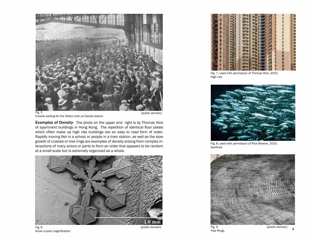
Examples of Density- The photo on the upper and right is by Thomas Hick of apartment buildings in Hong Kong. The repetition of identical floor plates which often make up high rise buildings are an easy to read form of order. Rapidly moving fish in a school or people in a train station, as well as the slow growth of crystals or tree rings are examples of density arising from complex in-teractions of many actors or parts to form an order that appears to be random at a small scale but is extremely organized as a whole.
4
Fig. 5Crowds waiting for the Sillton train at Carisle station
[public domain]
Fig. 6Snow crystal magnification
[public domain]
Fig. 8, used with permission of Rick Browne, 2010.Sardines
[public domain]Fig. 9Tree Rings
Fig. 7, used with permission of Thomas Hick, 2010.High rise
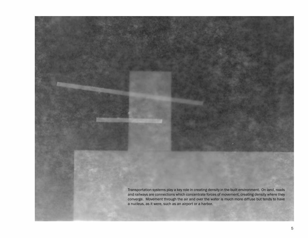
Transportation systems play a key role in creating density in the built environment. On land, roads and railways are connections which concentrate forces of movement, creating density where they converge. Movement through the air and over the water is much more diffuse but tends to have a nucleus, as it were, such as an airport or a harbor.
5
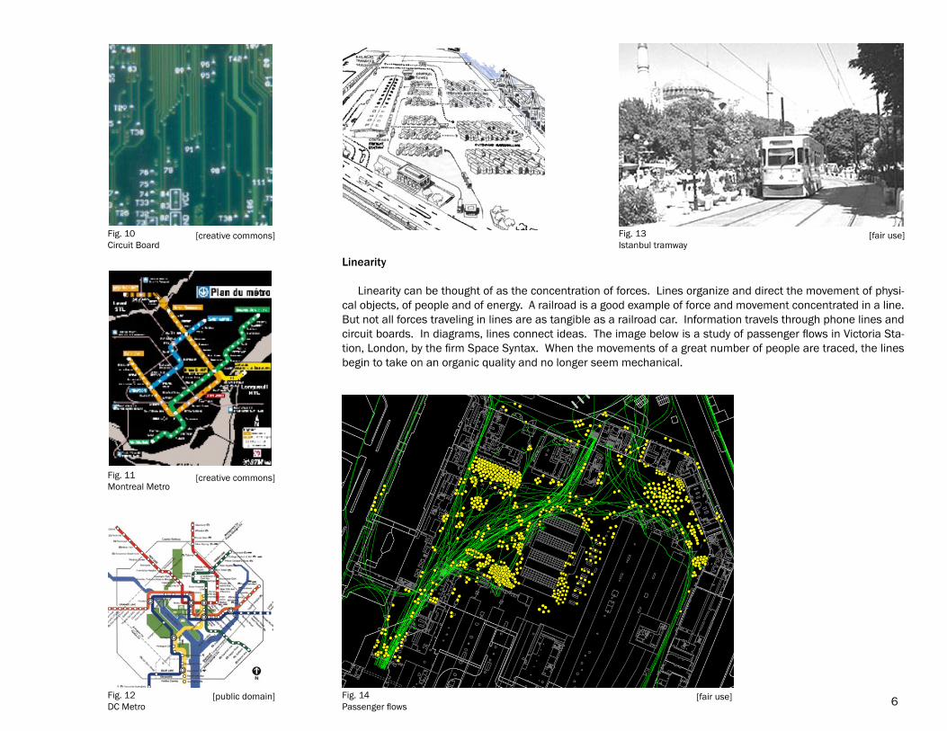
Linearity Linearity can be thought of as the concentration of forces. Lines organize and direct the movement of physi-cal objects, of people and of energy. A railroad is a good example of force and movement concentrated in a line. But not all forces traveling in lines are as tangible as a railroad car. Information travels through phone lines and circuit boards. In diagrams, lines connect ideas. The image below is a study of passenger flows in Victoria Sta-tion, London, by the firm Space Syntax. When the movements of a great number of people are traced, the lines begin to take on an organic quality and no longer seem mechanical.
6
Fig. 10Circuit Board
[creative commons]
Fig. 11Montreal Metro
[creative commons]
Fig. 12DC Metro
[public domain]
Fig. 13Istanbul tramway
[fair use]
Fig. 14Passenger flows
[fair use]
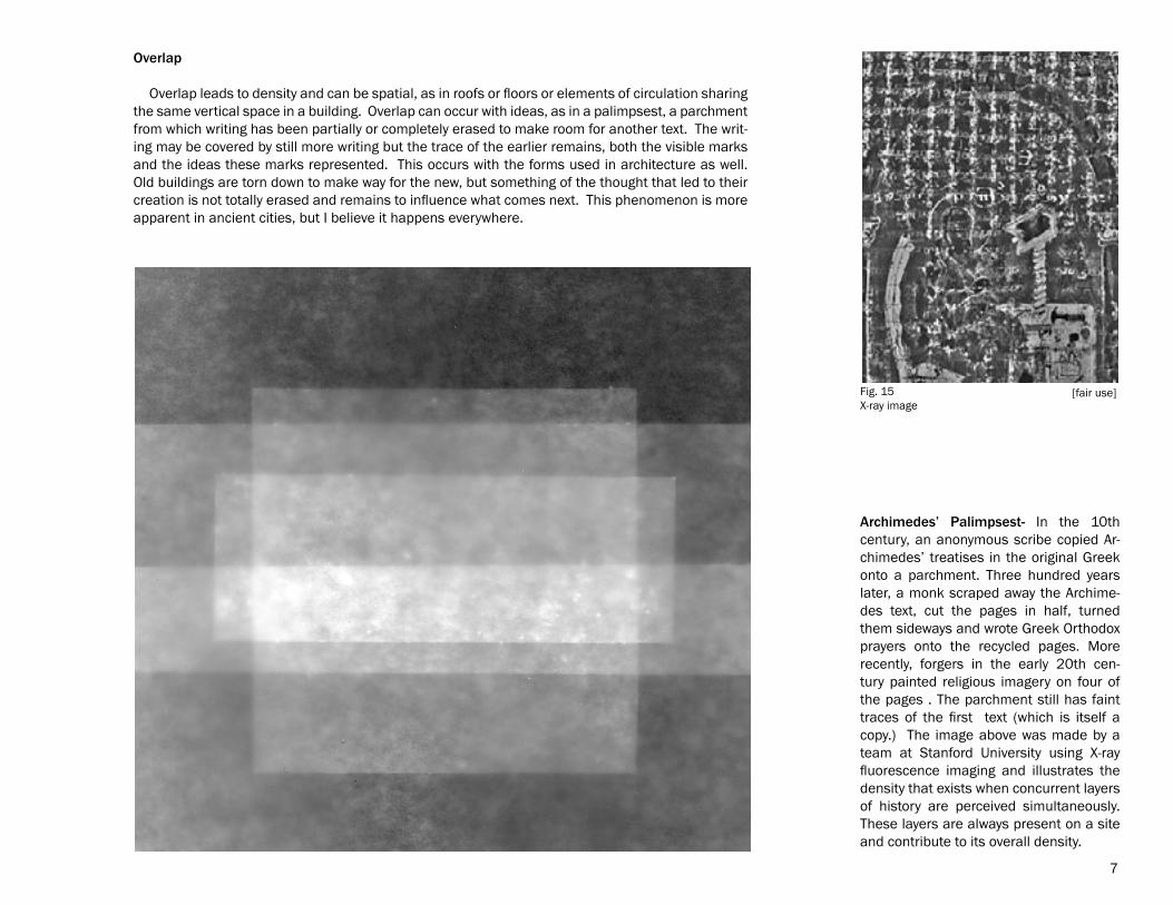
Archimedes’ Palimpsest- In the 10th century, an anonymous scribe copied Ar-chimedes’ treatises in the original Greek onto a parchment. Three hundred years later, a monk scraped away the Archime-des text, cut the pages in half, turned them sideways and wrote Greek Orthodox prayers onto the recycled pages. More recently, forgers in the early 20th cen-tury painted religious imagery on four of the pages . The parchment still has faint traces of the first text (which is itself a copy.) The image above was made by a team at Stanford University using X-ray fluorescence imaging and illustrates the density that exists when concurrent layers of history are perceived simultaneously. These layers are always present on a site and contribute to its overall density.
Overlap
Overlap leads to density and can be spatial, as in roofs or floors or elements of circulation sharing the same vertical space in a building. Overlap can occur with ideas, as in a palimpsest, a parchment from which writing has been partially or completely erased to make room for another text. The writ-ing may be covered by still more writing but the trace of the earlier remains, both the visible marks and the ideas these marks represented. This occurs with the forms used in architecture as well. Old buildings are torn down to make way for the new, but something of the thought that led to their creation is not totally erased and remains to influence what comes next. This phenomenon is more apparent in ancient cities, but I believe it happens everywhere.
7
Fig. 15X-ray image
[fair use]

In addition to the traces of previous habitation on a site, when a new building is envisioned it is not drawn on a truly blank parch-ment, so to speak. Rather, it is drawn over the traces of other examples of its building type. Precedents overlap one another and where they converge or join with the characteristics of the site and the requirements of the program they increase in density until they begin to solidify into a new form. One of the buildings that make up the mental palimpsest for this project is Smith-Miller + Hawkinson’s Pier 11 ferry terminal in lower Manhattan with its unobstructed open spaces and large overhanging steel roof. Another is Attilio Correa Lima’s seaplane station in Rio de Janeiro with a cantilevered upper level over massive concrete supports. Although the methods of construction differ and they were built in very different times and places, both structures have a sense of openness that seems appropriate for a place of arrival and departure.
8
Fig. 16, used with permission of Michael Moran, 2010.Smith-Miller + Hawkinson
Fig. 17Seaplane station
[fair use]
Fig. 18Seaplane station
[fair use]

Analysis of site forces
9
Joint between Europe and Asia
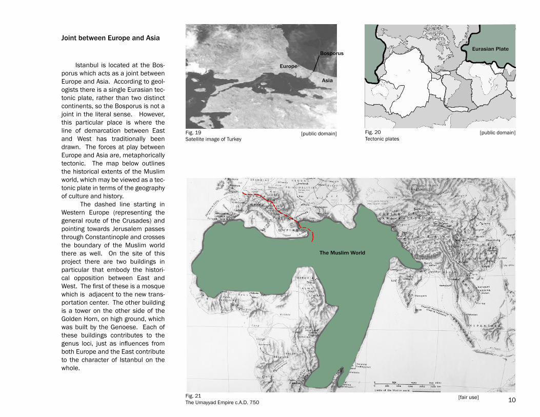
Istanbul is located at the Bos-porus which acts as a joint between Europe and Asia. According to geol-ogists there is a single Eurasian tec-tonic plate, rather than two distinct continents, so the Bosporus is not a joint in the literal sense. However, this particular place is where the line of demarcation between East and West has traditionally been drawn. The forces at play between Europe and Asia are, metaphorically tectonic. The map below outlines the historical extents of the Muslim world, which may be viewed as a tec-tonic plate in terms of the geography of culture and history. The dashed line starting in Western Europe (representing the general route of the Crusades) and pointing towards Jerusalem passes through Constantinople and crosses the boundary of the Muslim world there as well. On the site of this project there are two buildings in particular that embody the histori-cal opposition between East and West. The first of these is a mosque which is adjacent to the new trans-portation center. The other building is a tower on the other side of the Golden Horn, on high ground, which was built by the Genoese. Each of these buildings contributes to the genus loci, just as influences from both Europe and the East contribute to the character of Istanbul on the whole.
Asia
Europe
BosporusEurasian Plate
The Muslim World
10
Fig. 19Satellite image of Turkey
Fig. 21The Umayyad Empire c.A.D. 750
[public domain] Fig. 20Tectonic plates
[public domain]
[fair use]
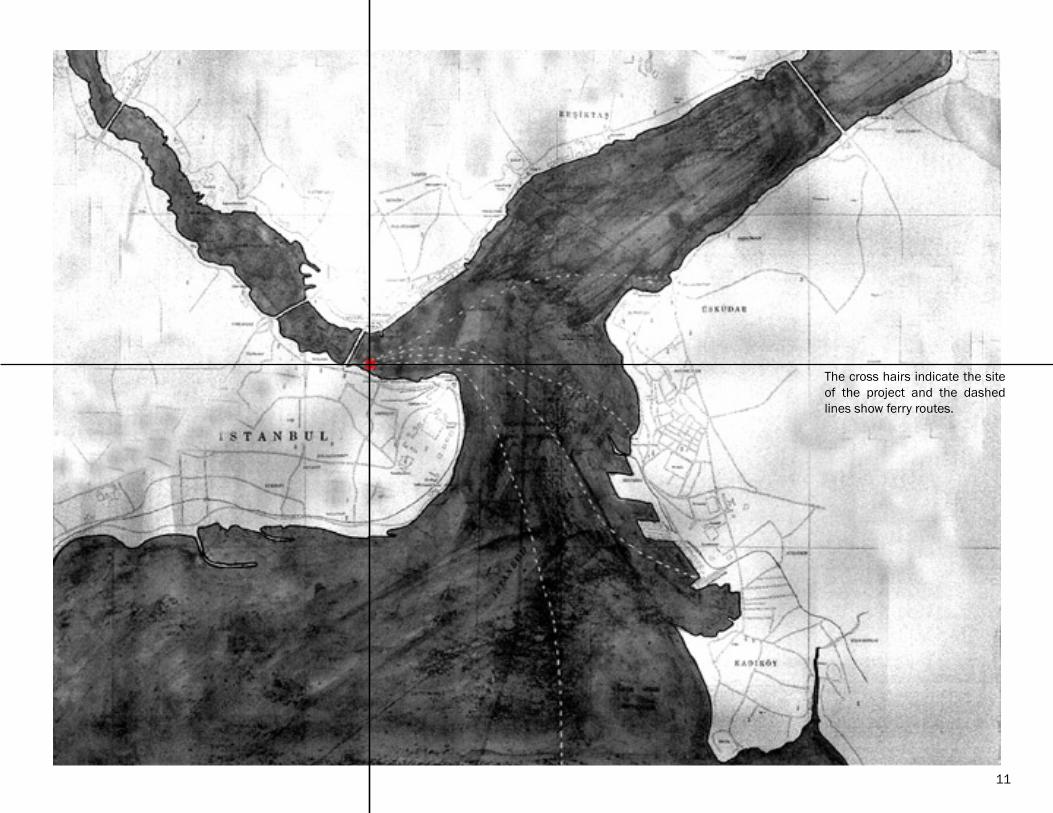
The cross hairs indicate the site of the project and the dashed lines show ferry routes.
11
��under roof
= dome
central axis
open courtyard
outer inner
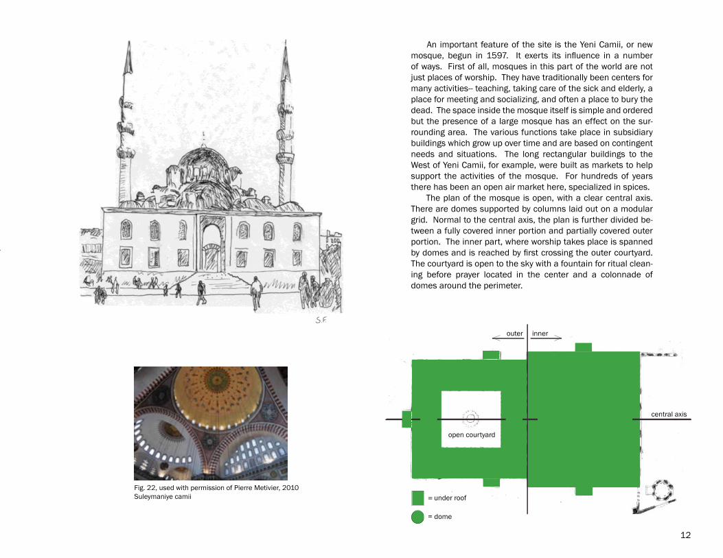
An important feature of the site is the Yeni Camii, or new mosque, begun in 1597. It exerts its influence in a number of ways. First of all, mosques in this part of the world are not just places of worship. They have traditionally been centers for many activities-- teaching, taking care of the sick and elderly, a place for meeting and socializing, and often a place to bury the dead. The space inside the mosque itself is simple and ordered but the presence of a large mosque has an effect on the sur-rounding area. The various functions take place in subsidiary buildings which grow up over time and are based on contingent needs and situations. The long rectangular buildings to the West of Yeni Camii, for example, were built as markets to help support the activities of the mosque. For hundreds of years there has been an open air market here, specialized in spices. The plan of the mosque is open, with a clear central axis. There are domes supported by columns laid out on a modular grid. Normal to the central axis, the plan is further divided be-tween a fully covered inner portion and partially covered outer portion. The inner part, where worship takes place is spanned by domes and is reached by first crossing the outer courtyard. The courtyard is open to the sky with a fountain for ritual clean-ing before prayer located in the center and a colonnade of domes around the perimeter.
12
Fig. 22, used with permission of Pierre Metivier, 2010Suleymaniye camii
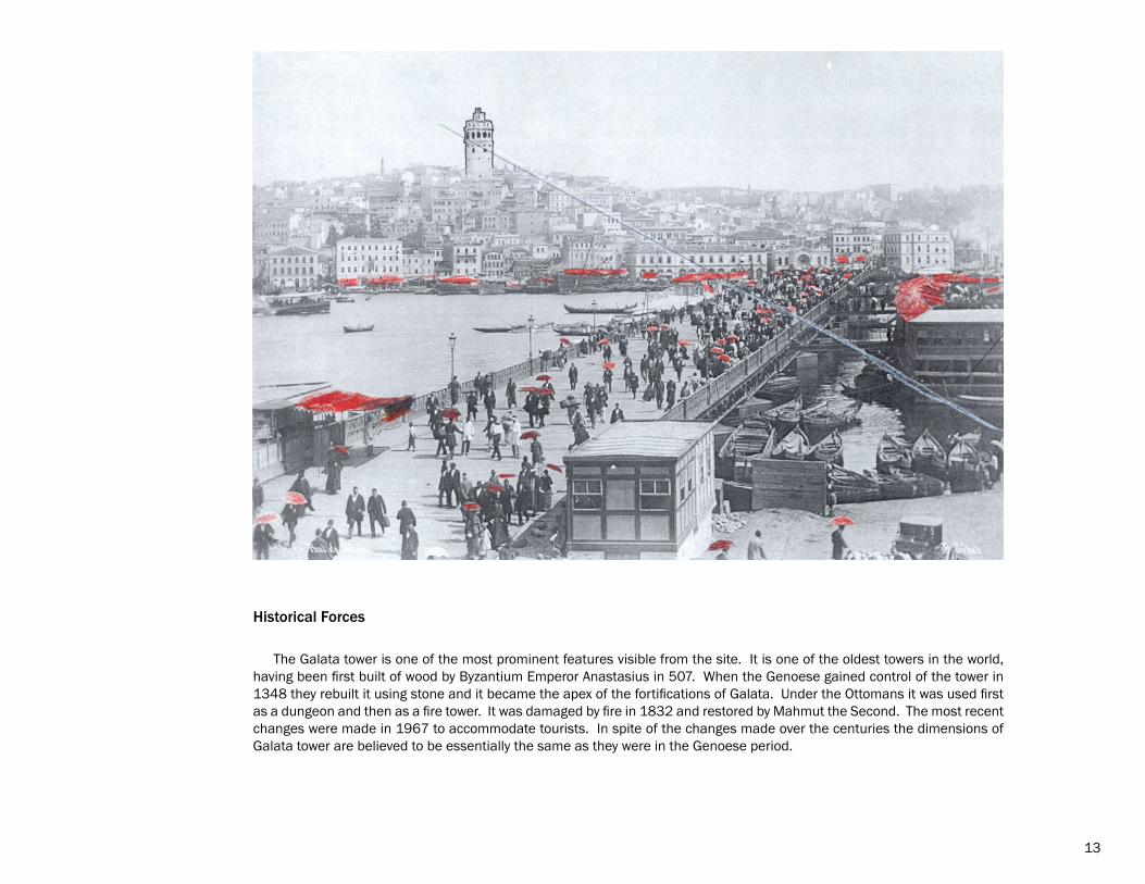
The Galata tower is one of the most prominent features visible from the site. It is one of the oldest towers in the world, having been first built of wood by Byzantium Emperor Anastasius in 507. When the Genoese gained control of the tower in 1348 they rebuilt it using stone and it became the apex of the fortifications of Galata. Under the Ottomans it was used first as a dungeon and then as a fire tower. It was damaged by fire in 1832 and restored by Mahmut the Second. The most recent changes were made in 1967 to accommodate tourists. In spite of the changes made over the centuries the dimensions of Galata tower are believed to be essentially the same as they were in the Genoese period.
13
Historical Forces
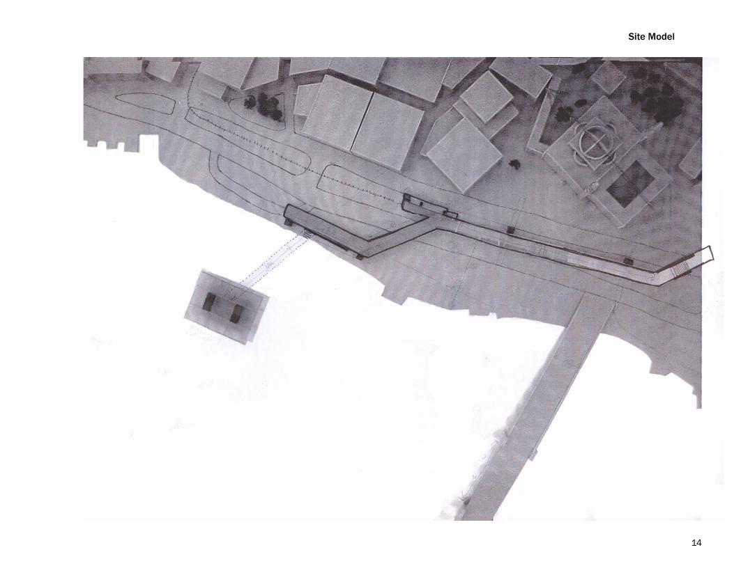
Site Model
14
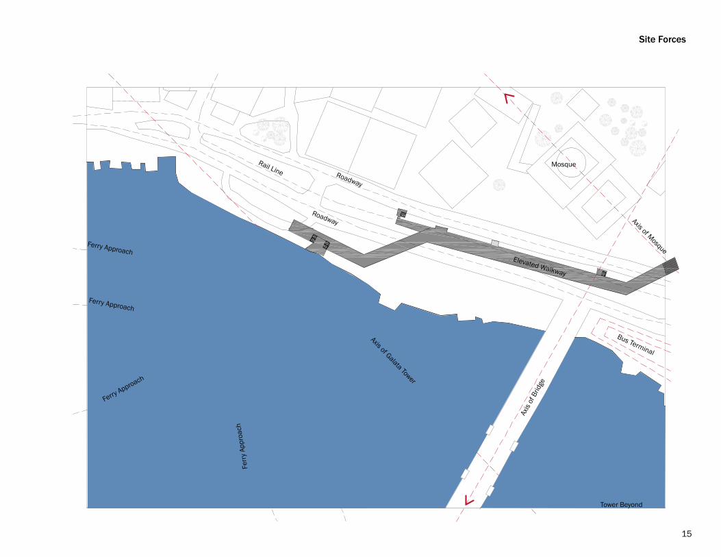
Site Forces
Axis of Mosque
Rail Line
Axis
of B
ridge
Bus Terminal
Roadway
Roadway
Axis of Galata Tower
Ferry Approach
Ferry Approach
Ferry Approach
Ferr
y Ap
proa
ch
Elevated Walkway
Mosque
Tower Beyond
15
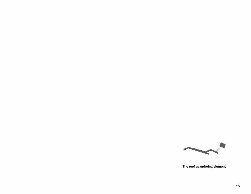
The roof as ordering element
16
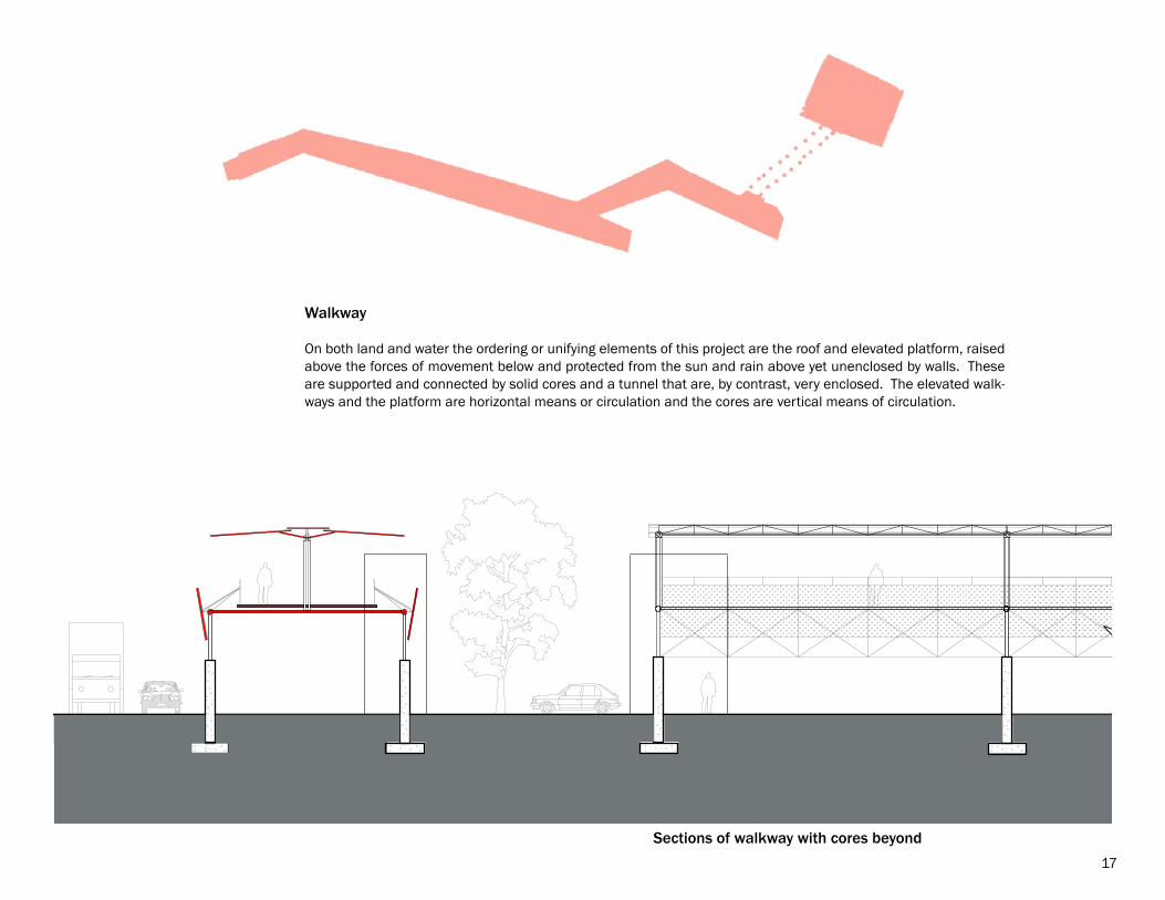
Walkway
On both land and water the ordering or unifying elements of this project are the roof and elevated platform, raised above the forces of movement below and protected from the sun and rain above yet unenclosed by walls. These are supported and connected by solid cores and a tunnel that are, by contrast, very enclosed. The elevated walk-ways and the platform are horizontal means or circulation and the cores are vertical means of circulation.
Sections of walkway with cores beyond17
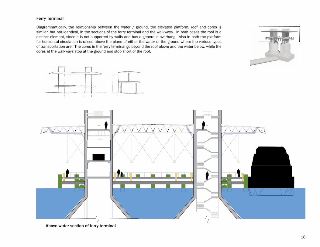
Above water section of ferry terminal
Diagrammatically, the relationship between the water / ground, the elevated platform, roof and cores is similar, but not identical, in the sections of the ferry terminal and the walkways. In both cases the roof is a distinct element, since it is not supported by walls and has a generous overhang. Also in both the platform for horizontal circulation is raised above the plane of either the water or the ground where the various types of transportation are. The cores in the ferry terminal go beyond the roof above and the water below, while the cores at the walkways stop at the ground and stop short of the roof.
18
Ferry Terminal
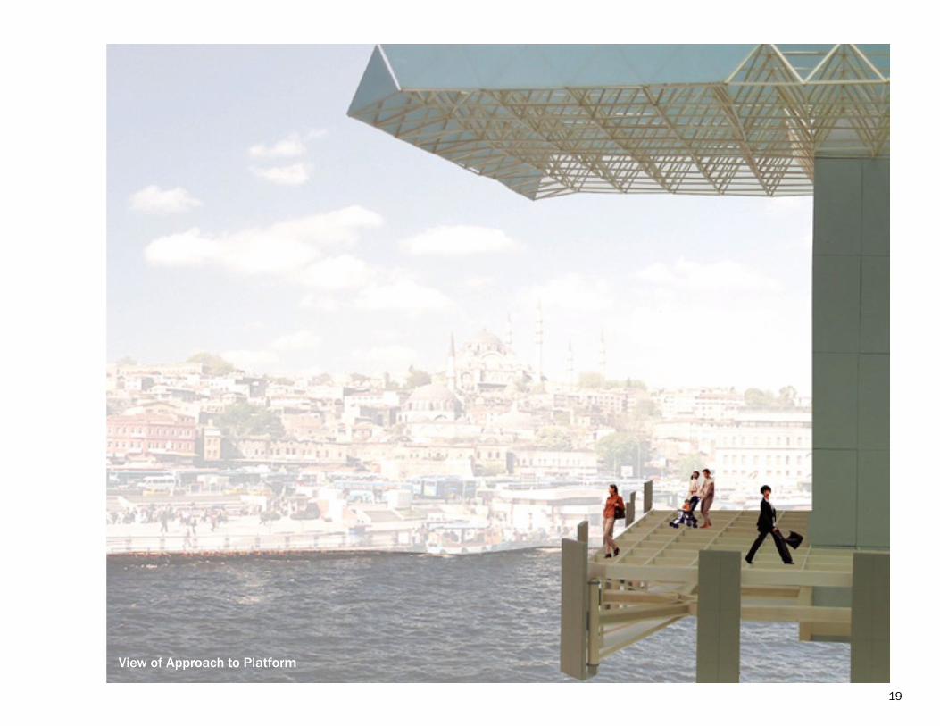
View of Approach to Platform
19
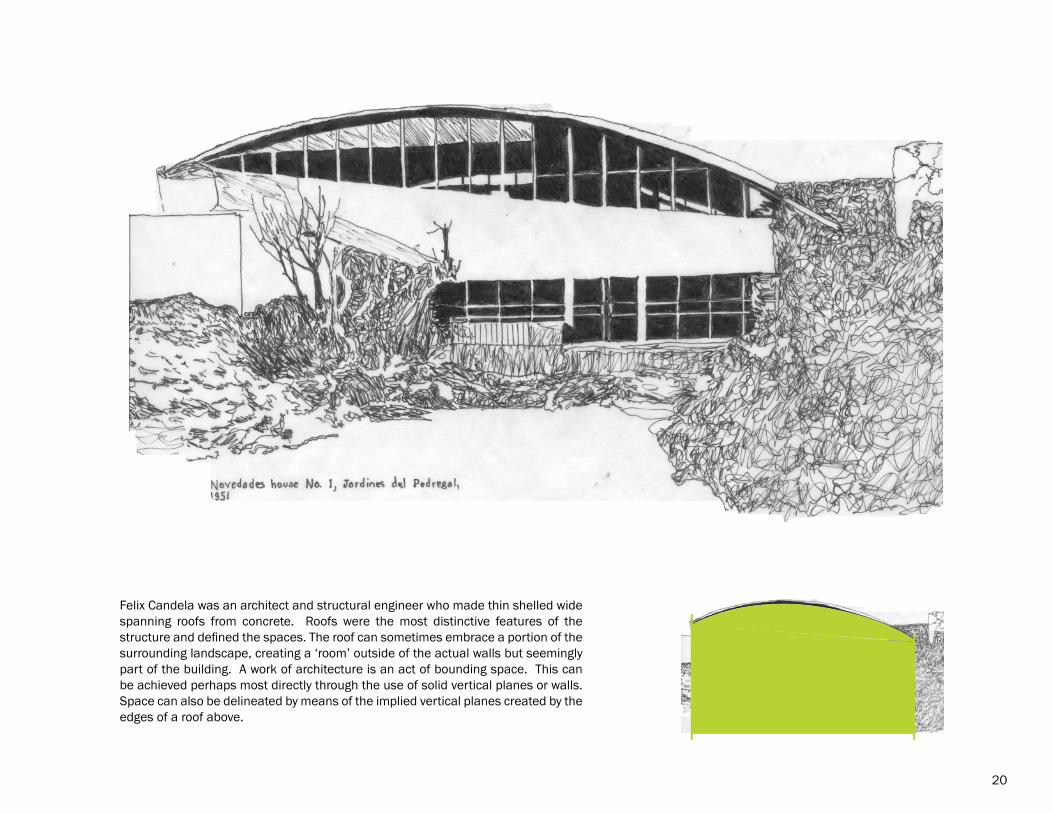
Felix Candela was an architect and structural engineer who made thin shelled wide spanning roofs from concrete. Roofs were the most distinctive features of the structure and defined the spaces. The roof can sometimes embrace a portion of the surrounding landscape, creating a ‘room’ outside of the actual walls but seemingly part of the building. A work of architecture is an act of bounding space. This can be achieved perhaps most directly through the use of solid vertical planes or walls. Space can also be delineated by means of the implied vertical planes created by the edges of a roof above.
20
������������������������
����
�����������������������������������
��������������������������������������
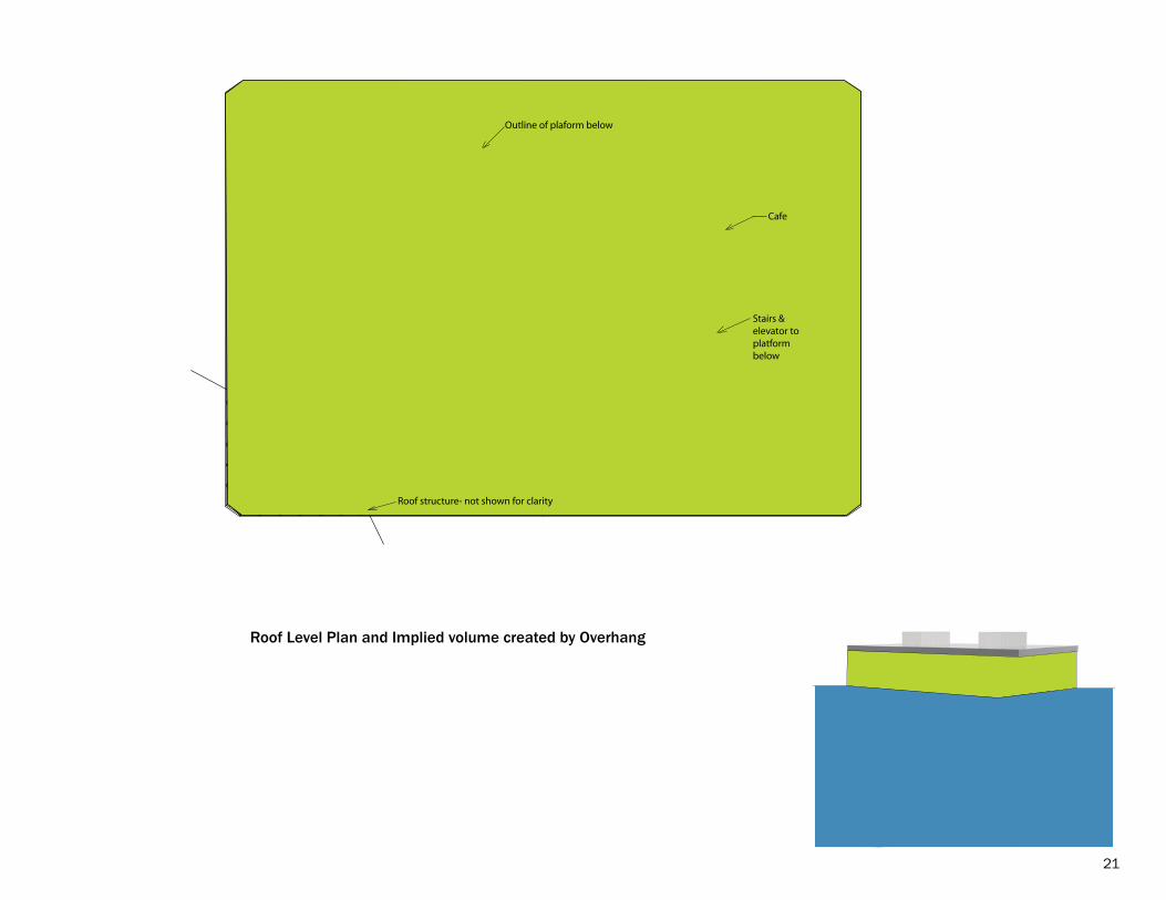
Roof Level Plan and Implied volume created by Overhang
21
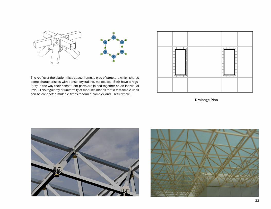
The roof over the platform is a space frame, a type of structure which shares some characteristics with dense, crystalline, molecules. Both have a regu-larity in the way their constituent parts are joined together on an individual level. This regularity or uniformity of modules means that a few simple units can be connected multiple times to form a complex and useful whole.
Drainage Plan
H
H H
H
H H
H H
HH
H
H
O
O
O
O
O
O
22
Joining at various scales
23

The border between water and land
In the early stages of the project the ferry terminal was an elaboration on the theme or concept of the existing terminal (shown on the right), which is a building on the land at the edge of the water. Istanbul is a city on the water, but due to its location there is no real variation in the water level because of either tides or flooding, so there is a long history of building close to the water’s edge. In the course of studying and responding to the forces present at the site the choice was made to take a more layered approach to the transition between land and water. A ferry terminal is a joint between water and land. When two disparate elements are in close proximity there needs to be some sort of buffer or gradation between them for the connection to not be jarring.
24
25
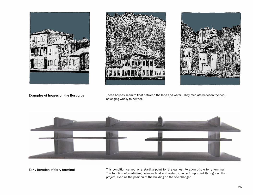
Early iteration of ferry terminal
Examples of houses on the Bosporus These houses seem to float between the land and water. They mediate between the two, belonging wholly to neither.
This condition served as a starting point for the earliest iteration of the ferry terminal. The function of mediating between land and water remained important throughout the project, even as the position of the building on the site changed.
26
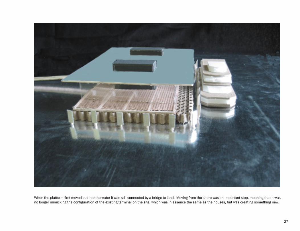
When the platform first moved out into the water it was still connected by a bridge to land. Moving from the shore was an important step, meaning that it was no longer mimicking the configuration of the existing terminal on the site, which was in essence the same as the houses, but was creating something new.
27
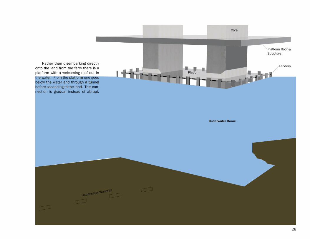
Underwater Walkway
Fenders
Platform Roof &Structure
Underwater Dome
Platform
Core
Rather than disembarking directly onto the land from the ferry there is a platform with a welcoming roof out in the water. From the platform one goes below the water and through a tunnel before ascending to the land. This con-nection is gradual instead of abrupt.
28
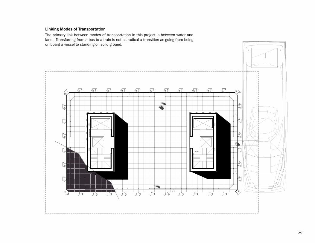
The primary link between modes of transportation in this project is between water and land. Transferring from a bus to a train is not as radical a transition as going from being on board a vessel to standing on solid ground.
Linking Modes of Transportation
29

Tunnel and Walkway
The tunnel has an elliptical cross-section and is sup-ported periodically by what could be thought of as min-iature versions of the main core. As the section shows, there is a platform suspended within the outer wall of the tunnel, which provides some continuity with the elevated walkways. The lights are positioned beneath the platform and wash the walls of the tunnel to give emphasis to the separation between the walkway and the outside of the tunnel.
30
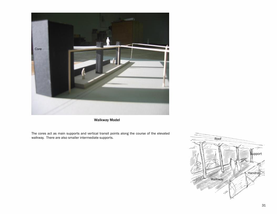
Walkway Model
Core
Handrail
Roof
Support
Walkway
The cores act as main supports and vertical transit points along the course of the elevated walkway. There are also smaller intermediate supports.
31
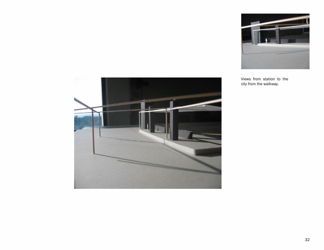
Views from station to the city from the walkway.
32

33
The walkway, a “street-in-the-air,” acts as part of “...a layered movement pattern that separates the various means of move-ment and gives to each its own geometry, its own formal expression.” This concept was used by Ali-son and Peter Smithson in their proposal for the Berlin Hauptstadt in 1957. The hope was that by using a network of elevated plat-forms to separate pedestri-ans from cars and trains, “The individual can experi-ence a new freedom..when the machine is sweetly used, it allows and so en-genders, consideration for others.” (from The Charged Void: Urbanism).
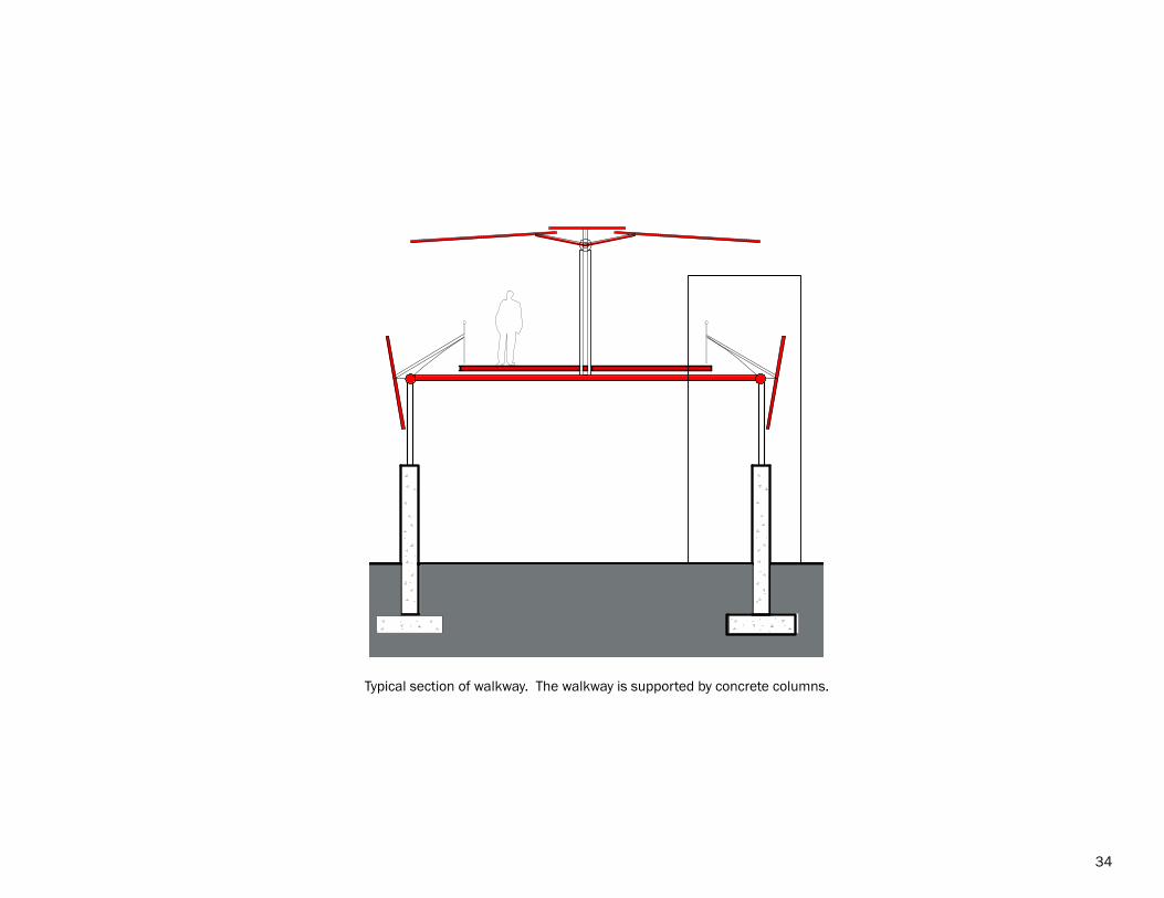
Typical section of walkway. The walkway is supported by concrete columns.
34
Lighting Plan
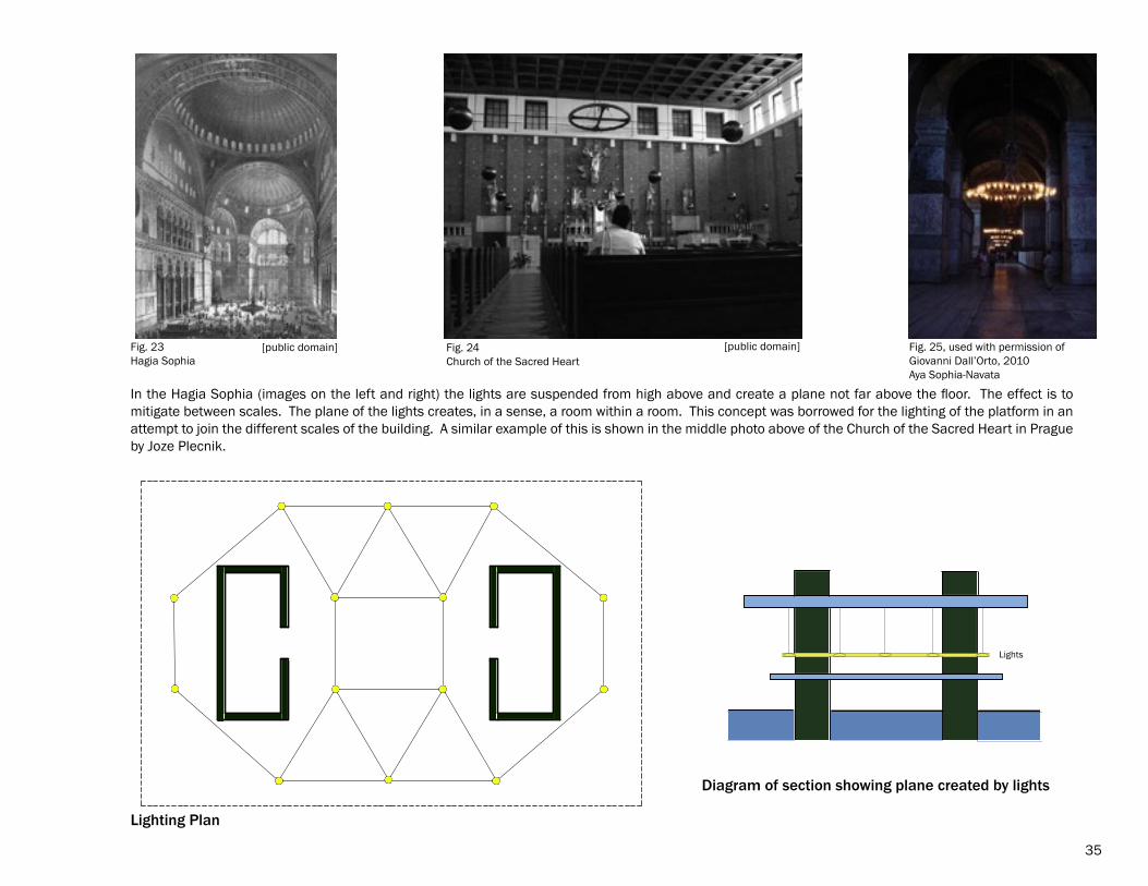
In the Hagia Sophia (images on the left and right) the lights are suspended from high above and create a plane not far above the floor. The effect is to mitigate between scales. The plane of the lights creates, in a sense, a room within a room. This concept was borrowed for the lighting of the platform in an attempt to join the different scales of the building. A similar example of this is shown in the middle photo above of the Church of the Sacred Heart in Prague by Joze Plecnik.
Lighting Plan
Lights
Diagram of section showing plane created by lights
35
Fig. 23Hagia Sophia
[public domain] Fig. 24Church of the Sacred Heart
[public domain] Fig. 25, used with permission ofGiovanni Dall’Orto, 2010Aya Sophia-Navata
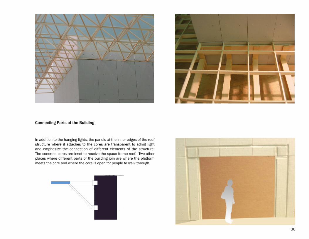
In addition to the hanging lights, the panels at the inner edges of the roof structure where it attaches to the cores are transparent to admit light and emphasize the connection of different elements of the structure. The concrete cores are inset to receive the space frame roof. Two other places where different parts of the building join are where the platform meets the core and where the core is open for people to walk through.
Connecting Parts of the Building
36

Structural considerations
37
����������
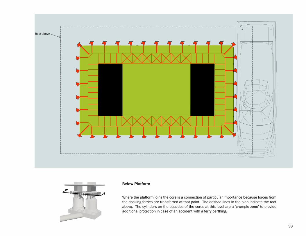
Where the platform joins the core is a connection of particular importance because forces from the docking ferries are transferred at that point. The dashed lines in the plan indicate the roof above. The cylinders on the outsides of the cores at this level are a ‘crumple zone’ to provide additional protection in case of an accident with a ferry berthing.
Below Platform
38

Ferry Specifications
Passenger Capacity: 350Length: 114 feetWidth: 32 feetDraft: 4 feetFreeboard: 8 feetTop Speed: 30 knotsGross Tonnage: 377 tonsPropulsion System: Propeller
Understanding the physical nature of the ferry boats was valuable. In order to think about a building of this type it is important to understand the forces involved. I began to realize that a moving boat has a great deal of energy, which needs to be dissipated. I learned about berthing angles and procedures and did simple calcula-tions using a spreadsheet to determine the characteris-tics of the fender system.
39
40
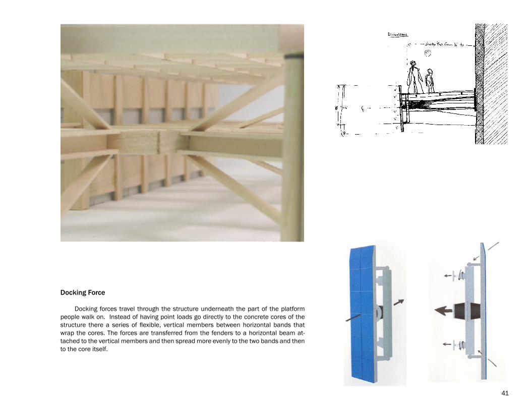
Docking Force
Docking forces travel through the structure underneath the part of the platform people walk on. Instead of having point loads go directly to the concrete cores of the structure there a series of flexible, vertical members between horizontal bands that wrap the cores. The forces are transferred from the fenders to a horizontal beam at-tached to the vertical members and then spread more evenly to the two bands and then to the core itself.
41
��
�
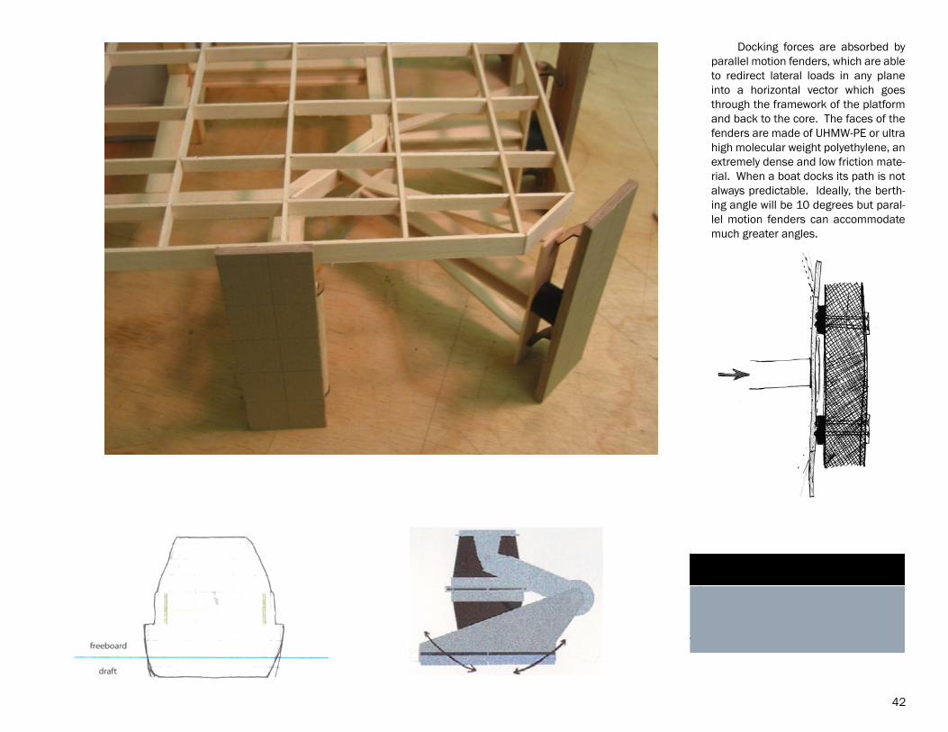
Center of Gravity
Docking forces are absorbed by parallel motion fenders, which are able to redirect lateral loads in any plane into a horizontal vector which goes through the framework of the platform and back to the core. The faces of the fenders are made of UHMW-PE or ultra high molecular weight polyethylene, an extremely dense and low friction mate-rial. When a boat docks its path is not always predictable. Ideally, the berth-ing angle will be 10 degrees but paral-lel motion fenders can accommodate much greater angles.
42
Construction Techniques
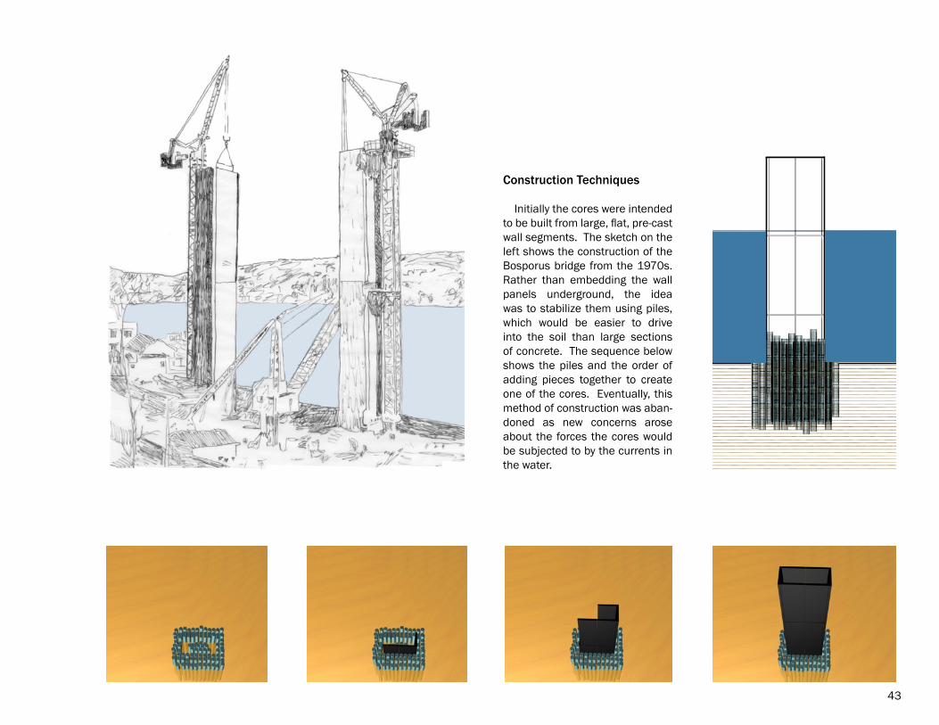
Initially the cores were intended to be built from large, flat, pre-cast wall segments. The sketch on the left shows the construction of the Bosporus bridge from the 1970s. Rather than embedding the wall panels underground, the idea was to stabilize them using piles, which would be easier to drive into the soil than large sections of concrete. The sequence below shows the piles and the order of adding pieces together to create one of the cores. Eventually, this method of construction was aban-doned as new concerns arose about the forces the cores would be subjected to by the currents in the water.
43
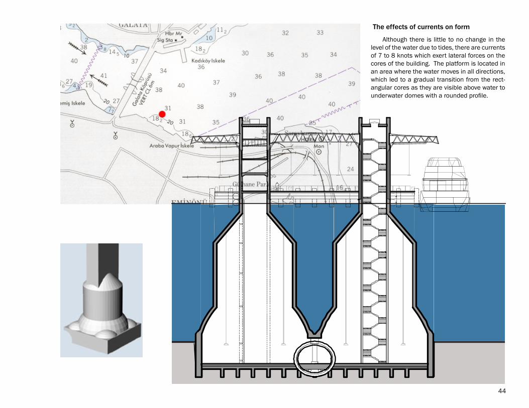
Although there is little to no change in the level of the water due to tides, there are currents of 7 to 8 knots which exert lateral forces on the cores of the building. The platform is located in an area where the water moves in all directions, which led to a gradual transition from the rect-angular cores as they are visible above water to underwater domes with a rounded profile.
The effects of currents on form
44
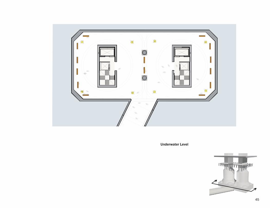
Underwater Level
45
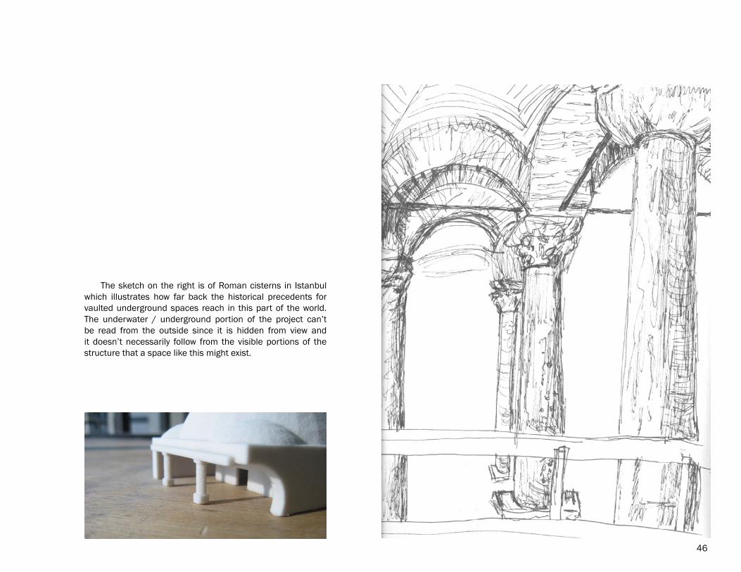
The sketch on the right is of Roman cisterns in Istanbul which illustrates how far back the historical precedents for vaulted underground spaces reach in this part of the world. The underwater / underground portion of the project can’t be read from the outside since it is hidden from view and it doesn’t necessarily follow from the visible portions of the structure that a space like this might exist.
46
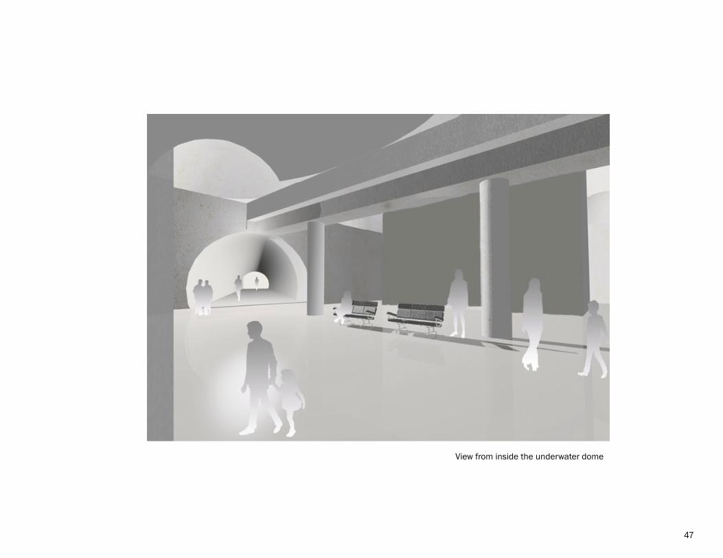
View from inside the underwater dome
47
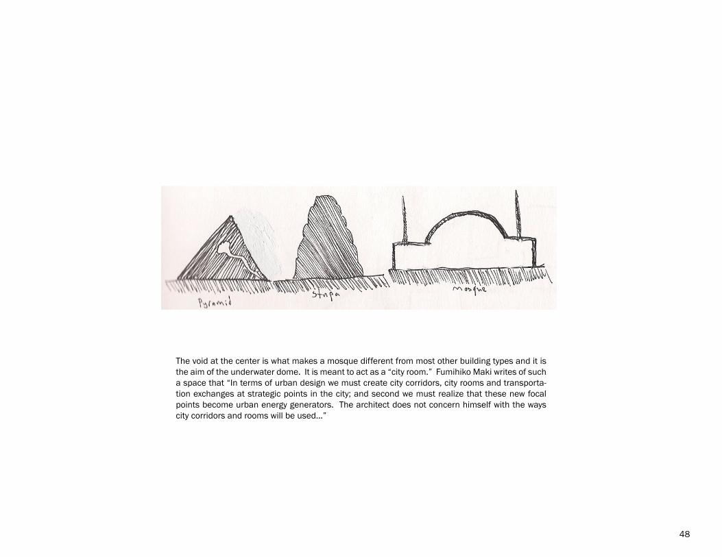
The void at the center is what makes a mosque different from most other building types and it is the aim of the underwater dome. It is meant to act as a “city room.” Fumihiko Maki writes of such a space that “In terms of urban design we must create city corridors, city rooms and transporta-tion exchanges at strategic points in the city; and second we must realize that these new focal points become urban energy generators. The architect does not concern himself with the ways city corridors and rooms will be used...”
48
49
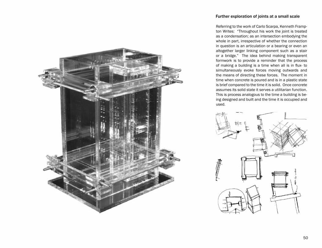
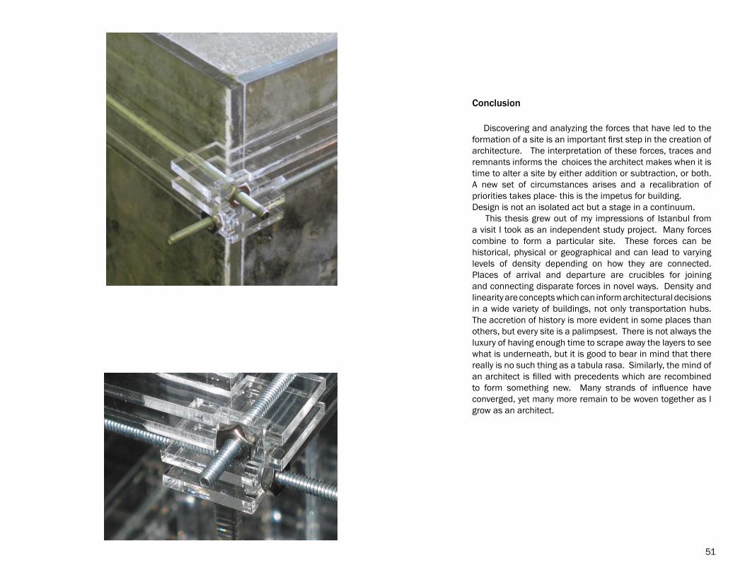
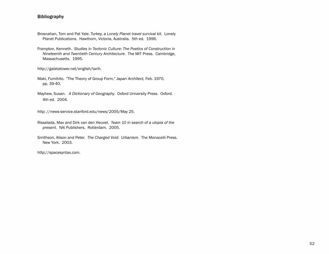
Referring to the work of Carlo Scarpa, Kenneth Framp-ton Writes: “Throughout his work the joint is treated as a condensation; as an intersection embodying the whole in part, irrespective of whether the connection in question is an articulation or a bearing or even an altogether larger linking component such as a stair or a bridge.” The idea behind making transparent formwork is to provide a reminder that the process of making a building is a time when all is in flux- to simultaneously evoke forces moving outwards and the means of directing these forces. The moment in time when concrete is poured and is in a plastic state is brief compared to the time it is solid. Once concrete assumes its solid state it serves a utilitarian function. This is process analogous to the time a building is be-ing designed and built and the time it is occupied and used.
Further exploration of joints at a small scale
50
Conclusion
Discovering and analyzing the forces that have led to the formation of a site is an important first step in the creation of architecture. The interpretation of these forces, traces and remnants informs the choices the architect makes when it is time to alter a site by either addition or subtraction, or both. A new set of circumstances arises and a recalibration of priorities takes place- this is the impetus for building. Design is not an isolated act but a stage in a continuum. This thesis grew out of my impressions of Istanbul from a visit I took as an independent study project. Many forces combine to form a particular site. These forces can be historical, physical or geographical and can lead to varying levels of density depending on how they are connected. Places of arrival and departure are crucibles for joining and connecting disparate forces in novel ways. Density and linearity are concepts which can inform architectural decisions in a wide variety of buildings, not only transportation hubs. The accretion of history is more evident in some places than others, but every site is a palimpsest. There is not always the luxury of having enough time to scrape away the layers to see what is underneath, but it is good to bear in mind that there really is no such thing as a tabula rasa. Similarly, the mind of an architect is filled with precedents which are recombined to form something new. Many strands of influence have converged, yet many more remain to be woven together as I grow as an architect.
51
Bibliography
Brosnahan, Tom and Pat Yale. Turkey, a Lonely Planet travel survival kit. Lonely Planet Publications. Hawthorn, Victoria, Australia. 5th ed. 1996.
Frampton, Kenneth. Studies in Tectonic Culture: The Poetics of Construction in Nineteenth and Twentieth Century Architecture. The MIT Press. Cambridge, Massachusetts. 1995.
http://galatatower.net/english/tarih.
Maki, Fumihito. "The Theory of Group Form," Japan Architect, Feb. 1970, pp. 39-40.
Mayhew, Susan. A Dictionary of Geography. Oxford University Press. Oxford. 4th ed. 2004.
http: //news-service.stanford.edu/news/2005/May 25.
Risselada, Max and Dirk van den Heuvel. Team 10 in search of a utopia of the present. NAi Publishers. Rotterdam. 2005.
Smithson, Alison and Peter. The Charged Void: Urbanism. The Monacelli Press. New York. 2003.
http://spacesyntax.com.
52
53
Image Credits
Unless noted otherwise all images are the work of the author.
Fig. 1 [fair use]Risselada, Max and Dirk van Heuval. Team 10 in search of a utopia of the present. NAi Publishers. Rotterdam. 2005. p.48. Fair use determination attached.
Fig. 2 [fair use]Intermodal Steel Building Units Association Website. Image retrieved December 3, 2009 from http://www.isbu-info.org. Fair use determination attached.
Fig. 3 [with permission]Harrison, Chris, Carnegie Mellon University. World city-to-city connections. Image retrieved December 3, 2009 from http://www.chrisharrison.net/projects/internet map. Permission letter attached.
Fig. 4 [public domian]Satelite image of Noordoost Polder. Image retrieved December 2, 2009 from http://commons.wikipedia.org/wiki/file:satelite_image_of_nooroostpolder_netherlands. [This image is in the public domain because it is a screenshot from NASA's globe software using a public domain layer such as Blue Marble, MODIS, Landsat, SRTM, USGS, or GLOBE.]
Fig. 5 [public domain]Crowds waiting for the Sillton train at Carlisle station, Whit Monday, 1933. Image retrieved January 30, 2010 from http://www.myweb.tiscali.co.uk/hstch/railway 36. [This image is in the public domain because the photographer is unknown and it was created in 1933. Works published between 1923 and 1963 have a maximum of 67 years copyright protection before passing into the public domain.}
Fig. 6 [public domain]Snow crystal magnification series. Image retrieved September 16, 2008 from http;//en.wikipedia.org/wiki/file:LT-SEM_snow_crystal_magnification_series_1. [This image is in the public domain because it contains materials that originally came from the Agricultural Research Service, the research agency of the United States Department of Agriculture.]
Fig.7 [with permission]High Rise. Image retrieved February 26, 2010 from http://www.thomashick.com. Permission letter attached.
Fig. 8 [with permission](c)Monterey Bay Aquarium, photo by Rick Browne. Image retrieved September 16 2008 from http://mbari.org/news/news_releases/2003. Permission letter attached.
Fig. 9 [public domain]Tree rings. This image is in the public domain because it has been released into the public domain by its author, Arpingstone. Image retrieved February 26, 2010 from http://en.wikipedia.org/wiki/File: Tree.ring.arp.
Fig. 10 [creative commons]Circuit board. Image retrieved September 16, 2008 from http;//freefoto.com. [This image is licensed under the terms of creative commons attribution-non-commercial-no derivitive works 3.0 license.] Creative commons licensing documentation attached.
Fig. 11 [creative commons]Montreal Metro map, designed and drawn by Matthew McLauchin 2007. Image retrieved September 16, 2008 from http://commons.wikimedia.org/file:MTL_Metro_map. [This image is licensed under the terms of creative commons attribution share alike 3.0 license.] Creative commons licensing documentation attached.
Fig. 12 [public domain]DC Metro map. Image retrieved September 16, 2008 from http://www.wmata.com. [Image produced by Washington Metopolitan Area Transit Authority, a branch of the U.S. government, so it is in the public domain.]
Fig. 13 [fair use]Istanbul tramway. Image retrieved September 16, 2008 from http://www.subways.net/turkey/istanbul. Fair use determination attached.
Fig. 14 [fair use]Passenger Flows. Image retrieved December 4, 2009 from http://www.spacesyntax.com/en/downloads/gallery/desktop-background. Fair use determination attached.
Fig. 15 [fair use]X-ray image. Image retrieved September 16, 2008 from http://www.news-service.stanford.edu/news/2005/may 25. Fair use determination attached.
Fig. 16 [with permission]Smith-Miller + Hawkinson. Image copyright Michael Moran, photographer. Image retrieved March 2, 2010 from http://www.smarch.com. Permission letters attached.
Fig. 17 [fair use]Seaplane Station. Andreoli, Elisabeta and Adrian Forty. Brazil’s Modern Architecture. Phaidon Press. New York. P. 17. Fair use determination attached.
Fig. 18 [fair use]Seaplane Station. Andreoli, Elisabeta and Adrian Forty. Brazil’s Modern Architecture. Phaidon Press. New York. P. 17. Fair use determination attached.
Fig. 19 [public domain]Satellite image of Turkey. Image retrieved September 16, 2008 from http://visible earth.nasa.gov. [This image is in the public domain because it is a screen-shot from NASA's globe software using MODIS, a public domain layer.]
54

55
Fig. 20 [public domain]Tectonic plates. Image retrieved May 30, 2009 from http;//pubs.usgs.gov/publications/text/slabs.html. [This image is in the public domain because it conta-tains materials that originally came from the United States Geological Survey, an agency of the United States Department of Interior.]
Fig. 21 [fair use]The Umayyad Empire c.A.D. 750. Brice, W. C. An Historical Atlas of Islam. E. J. Brill. Leiden, The Netherlands. 1981. Fair use determination attached.
Fig. 22 [with permission]Pierre Metivier, phototgraher. Suleymaniye Camii. Image retrieved February 26, 2010 from http://www.sacred-destinations.com/turkey/images/istanbul/suleymaniye-interior. Permission letter attached.
Fig. 23 [public domain]Hagia sophia. Historical Lithograph by the Fossati brothers. 1852. Image retrieved February 26, 2010 from hppt://www.sacred-destinations.com/turkey/hagia-sophia-photos/webphotosprofiles/600-nave-lithograph. [This image is in the public domain because it was produced in 1852.]
Fig. 24 [public domain]Church of the Sacred Heart. Image retrieved on February 28, 2010 from http://commons.wikipedia.org/wiki/File:Church_of_Jiriho_z_podiebrad. Documen-taion of public domain criteria attached.
Fig. 25 [with permission]Giovanni Dall’Orto, photographer. Aya Sophia-Navata. Image retrieved March 1, 2010 from http://commons.wikimedia.org/wiki/File:DSCo4027a_Istanbul_-_Aya_Navata_-_Foto_G._Dall. Copyright holder license attached.