EFFECT OF SYNERGIC CONTROLLED PULSED AND MANUAL GAS … · EFFECT OF SYNERGIC CONTROLLED PULSED AND...
7
A R C H I V E S O F M E T A L L U R G Y A N D M A T E R I A L S Volume 58 2013 Issue 4 DOI: 10.2478/amm-2013-0122 T. TEKER * EFFECT OF SYNERGIC CONTROLLED PULSED AND MANUAL GAS METAL ARC WELDING PROCESSES ON MECHANICAL AND METALLURGICAL PROPERTIES OF AISI 430 FERRITIC STAINLESS STEEL WPLYW AUTOMATYCZNEGO I RĘCZNEGO SPAWANIA ELEKTRODĄ TOPLIOWĄ NA WLAŚCIWOŚCI MECHANICZNE I METALURGICZNE FERRYTYCZNEJ STALI NIERDZEWNEJ AISI 430 The gas metal arc is widely used in manufacturing industries because of the high metal deposition rate and ease of automation with better weld quality at permissible cost than other welding processes in joining similar and dissimilar metals. AISI 430 steel is normally difficult to weld by melting methods, due to the associated problems such as grain growth. For this purpose, AISI 430 ferritic stainless steel couples of 10 mm thick were welded by the synergic controlled pulsed (GMAW-P) and manual gas metal arc (GMAW) welding techniques. The interface appearances of the welded specimens were examined by scanning electron microscopy (SEM). Structural changes in the weld zone were analysed by energy dispersive spectrometry (EDS) and X-ray diffraction (X-RD). Microhardness, notch charpy and tensile tests were conducted to determine the mechanical properties of specimens. Accordingly, the best result was obtained from the GMAW-P technique. Keywords: D. Welding, E. Mechanical, F. Microstructure Spawanie elektrodą topliwą w oslonie gazów aktywnych jest szeroko stosowane w przemyśle wytwórczym, ze względu na wysokie tempo osadzania metalu i latwość automatyzacji oraz lepszą jakości spoiny przy dopuszczalnych kosztach niż w wypadku innych procesów spawania podobnych i różnych metali. Stal AISI 430 jest trudna do spawania metodami nadtapiania (z elektrodą nietopliwą), ze względu na związane z nimi problemy takie jak wzrost ziarna. Elementy ze stali ferrytycznej AISI 430 o grubości 10 mm zostaly zespawane techniką GMAW-P i GMAW. Do badania morfologii spawanych próbek wykorzystano metodę skaningowej mikroskopii elektronowej (SEM). Zmiany strukturalne w strefie spoiny analizowano metodą spektrome- trii z dyspersją energii (EDS) i dyfrakcji rentgenowskiej (X-RD). Pomiary mikrotwardości, udarności i próby rozciągania przeprowadzono w celu określenia wlaściwości mechanicznych próbek. Stwierdzono, że najlepszy wynik uzyskano dla spoin wytworzonych techniką GMAW-P. 1. Introduction In the industry, GMAW is the most commonly used method for welding ferrous and nonferrous materials. It is a melting welding method used in both manufacturing and re- pairing operations [1-3]. GMAW has various advantages over other melting welding methods. High welding speed, large metal deposition, and spatter free welding are some of its advantages. In addition, it is applicable for a wide variety of commercial metals and alloys such as carbon steel, stainless steel, copper and aluminum. Furthermore, it is a mechanised method and allows robot use [2,4]. GMAW-P mode can also be regarded as wire-feed speed control of mean current. Power supply and wire-feeder are directly linked in such a way that means current is determined by wire-feed rate to ensure sta- ble arc. The pulse waveform produced by this type of control has constant peak duration and excess current. Variable pulse parameters are peak current, base current and base current duration. This control can only be operated in the ?xed ranges of mean current as large mean current might produce multiple droplets detachments per pulse [1,5]. The current pulsing reduces overall heat input without any spatter [6]. It is a variation of constant current welding which involves cycling of the welding current from a high to a low level at a selected regular frequency [7,8]. This process works by forming one droplet of molten metal at the end of the electrode per pulse [9]. The right amount of current is then added to push that droplet across the arc and into the puddle. The detachment time is inversely proportional to the peak current magnitude [10]. In contrast to constant current welding, the heat energy required to melt the base material, supplied only during peak current pulses for brief intervals of time allows the heat to dissipate into the base material lead- ing to a narrower HAZ. Thus, it provides “cooling off” period between subsequent pulses, which reduces the plate distortion [11]. The temperature of weld pool rises due to an exother- mic reaction between argon and oxygen or carbon dioxide. In welding of steel, oxygen or carbon dioxide is mixed with ar- gon. Therefore, oxygen accelerates the forming of low melting * UNIVERSITY OF ADIYAMAN, FACULTY OF ENGINEERING, DEPARTMENT OF MATERIALS ENGINEERING, 02040, ADIYAMAN, TURKEY.
Transcript of EFFECT OF SYNERGIC CONTROLLED PULSED AND MANUAL GAS … · EFFECT OF SYNERGIC CONTROLLED PULSED AND...
A R C H I V E S O F M E T A L L U R G Y A N D M A T E R I A L S
Volume 58 2013 Issue 4
DOI: 10.2478/amm-2013-0122
T. TEKER∗
EFFECT OF SYNERGIC CONTROLLED PULSED AND MANUAL GAS METAL ARC WELDING PROCESSES ON MECHANICALAND METALLURGICAL PROPERTIES OF AISI 430 FERRITIC STAINLESS STEEL
WPŁYW AUTOMATYCZNEGO I RĘCZNEGO SPAWANIA ELEKTRODĄ TOPLIOWĄ NA WŁAŚCIWOŚCI MECHANICZNEI METALURGICZNE FERRYTYCZNEJ STALI NIERDZEWNEJ AISI 430
The gas metal arc is widely used in manufacturing industries because of the high metal deposition rate and ease ofautomation with better weld quality at permissible cost than other welding processes in joining similar and dissimilar metals.AISI 430 steel is normally difficult to weld by melting methods, due to the associated problems such as grain growth. For thispurpose, AISI 430 ferritic stainless steel couples of 10 mm thick were welded by the synergic controlled pulsed (GMAW-P)and manual gas metal arc (GMAW) welding techniques. The interface appearances of the welded specimens were examinedby scanning electron microscopy (SEM). Structural changes in the weld zone were analysed by energy dispersive spectrometry(EDS) and X-ray diffraction (X-RD). Microhardness, notch charpy and tensile tests were conducted to determine the mechanicalproperties of specimens. Accordingly, the best result was obtained from the GMAW-P technique.
Keywords: D. Welding, E. Mechanical, F. Microstructure
Spawanie elektrodą topliwą w osłonie gazów aktywnych jest szeroko stosowane w przemyśle wytwórczym, ze względuna wysokie tempo osadzania metalu i łatwość automatyzacji oraz lepszą jakości spoiny przy dopuszczalnych kosztach niż wwypadku innych procesów spawania podobnych i różnych metali. Stal AISI 430 jest trudna do spawania metodami nadtapiania(z elektrodą nietopliwą), ze względu na związane z nimi problemy takie jak wzrost ziarna. Elementy ze stali ferrytycznej AISI430 o grubości 10 mm zostały zespawane techniką GMAW-P i GMAW. Do badania morfologii spawanych próbek wykorzystanometodę skaningowej mikroskopii elektronowej (SEM). Zmiany strukturalne w strefie spoiny analizowano metodą spektrome-trii z dyspersją energii (EDS) i dyfrakcji rentgenowskiej (X-RD). Pomiary mikrotwardości, udarności i próby rozciąganiaprzeprowadzono w celu określenia właściwości mechanicznych próbek. Stwierdzono, że najlepszy wynik uzyskano dla spoinwytworzonych techniką GMAW-P.
1. Introduction
In the industry, GMAW is the most commonly usedmethod for welding ferrous and nonferrous materials. It isa melting welding method used in both manufacturing and re-pairing operations [1-3]. GMAW has various advantages overother melting welding methods. High welding speed, largemetal deposition, and spatter free welding are some of itsadvantages. In addition, it is applicable for a wide variety ofcommercial metals and alloys such as carbon steel, stainlesssteel, copper and aluminum. Furthermore, it is a mechanisedmethod and allows robot use [2,4]. GMAW-P mode can alsobe regarded as wire-feed speed control of mean current. Powersupply and wire-feeder are directly linked in such a way thatmeans current is determined by wire-feed rate to ensure sta-ble arc. The pulse waveform produced by this type of controlhas constant peak duration and excess current. Variable pulseparameters are peak current, base current and base currentduration. This control can only be operated in the ?xed ranges
of mean current as large mean current might produce multipledroplets detachments per pulse [1,5].
The current pulsing reduces overall heat input withoutany spatter [6]. It is a variation of constant current weldingwhich involves cycling of the welding current from a high toa low level at a selected regular frequency [7,8]. This processworks by forming one droplet of molten metal at the end ofthe electrode per pulse [9]. The right amount of current isthen added to push that droplet across the arc and into thepuddle. The detachment time is inversely proportional to thepeak current magnitude [10]. In contrast to constant currentwelding, the heat energy required to melt the base material,supplied only during peak current pulses for brief intervals oftime allows the heat to dissipate into the base material lead-ing to a narrower HAZ. Thus, it provides “cooling off” periodbetween subsequent pulses, which reduces the plate distortion[11]. The temperature of weld pool rises due to an exother-mic reaction between argon and oxygen or carbon dioxide. Inwelding of steel, oxygen or carbon dioxide is mixed with ar-gon. Therefore, oxygen accelerates the forming of low melting
∗ UNIVERSITY OF ADIYAMAN, FACULTY OF ENGINEERING, DEPARTMENT OF MATERIALS ENGINEERING, 02040, ADIYAMAN, TURKEY.
1030
oxides and reduces the surface tension of metal drops fallingfrom electrode wire. It also provides fine-grained metal struc-ture. Carbon dioxide is decomposed into carbon monoxideand oxygen at high arc temperature. Free oxygen is combinedwith elements in weld pool and gives the heat back, whichis gained during the decomposition. However, in this process,carbon is lost, which eventually results in decreasing hardness.Consequently, the shielding gas and its combinations are themost important parameters of GMAW method [12]. Necessityof combining materials with discrete features is due to thevariety of materials in industry, the requirement of differentmetal joints in various processes and economic concerns [13].Since materials to be welded have different physical, mechan-ical and metallurgical characteristics, welding process is moredifficult than the welding of similar materials [14]. In orderto have strength and continuity, a proper metal has to be cho-sen in welding materials with different physical and chemicalproperties [15]. GMAW method is also used for welding offerritic alloys such as austenite and nickel based filler metals,other forms of stainless steel or constructional steels and othermaterials. Austenitic stainless steel is predominant comparedto ferritic stainless steels with regard to toughness and duc-tility. Besides, brittleness caused by grain growth is avoidedusing austenitic electrode [16].
Ferritic stainless steel contains 16-30 wt.% Cr depend-ing on alloy element. Since this steel class is easy forming,cheap and resistant against atmospheric corrosion, it is com-monly used in architecture, interior and exterior decoration,food industry, wash boiler, dry machine, automotive industryand chemical industry. Normally, ferritic stainless steel has afine grained, ductile and ferritic structure. However, in melt-ing welding method, intergranular carbon settles and graincoarsening occurs at HAZ at temperature above 950◦C. Graincoarsening and intergranular carbon precipitation negativelyeffect on mechanical characteristics of welding joint and suchgrain coarsening results in lower toughness [16-18].
Several researchers examined the effects of pulsed currenton grain features at melting zone of welded joints for vari-ous materials. Ghosh et al., [19] have tried to improve weldtoughness with the variation of pulse parameters in vertical-upGMAW-P. The impact toughness of melting zone and HAZ incarbon steel weld joint was found to be enhanced significant-ly by the refinement of its microstructure and higher ferritecontent of weld metal with the increase of pulsed parametersfactor ϕ =[(Ib/Ip)ftb].
In the present study, ferritic stainless steel material [20]that is especially used to manufacture automobile exhaust iswelded by both GMAW and GMAW-P methods. Tensile, notchcharpy and microhardness tests are performed to determinethe strength of welded joint. In addition, microstructures de-veloped on weld metal and heat-affected zones (HAZ) areanalysed and grain morphology is examined.
2. Materials and method
Similar ferritic stainless steel (AISI 430) obtained frommarket, and 316L austenitic stainless steel wire of 1 mmis used in experiments. The results of chemical analyses ofthese materials are listed in Table 1, and mechanical prop-
erties are given in Table 2. The dimensions of specimensare 130×100×10 mm, and the specimens have 60◦V weld-ing groove. GMAW and GMAW-P was performed by MI-GATRONIC KME 400 model automated welding machine.The mixture of Ar + 2%O2 gas was used as shielding gasatmosphere. The welding speed was 4 mm/s and wire feedspeed was set to 3.2 m/min. The welding voltage was 22.5 V,and a constant gas flow rate of 16 l/min was selected. Weldingparameters used in this study are listed in Table 3. The weldingwas carried out by filling the weld groove in multi-passes (2passes) at the top and in a single pass at the bottom for eachother.
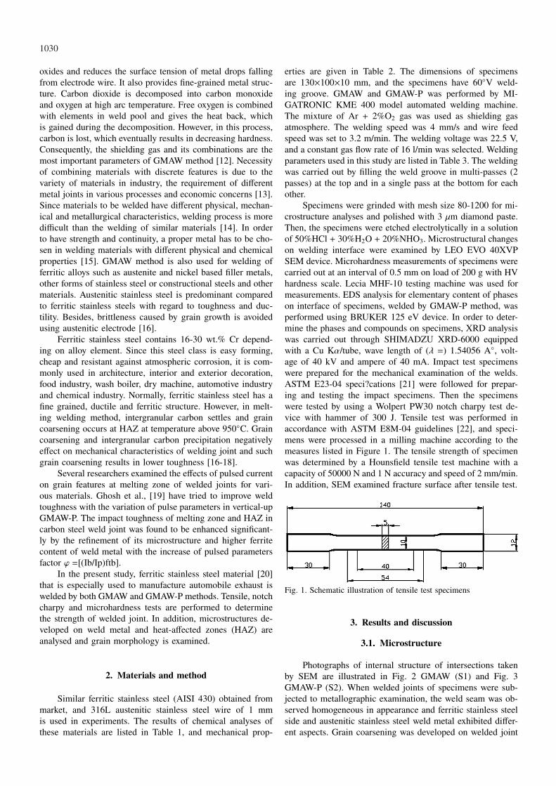
Specimens were grinded with mesh size 80-1200 for mi-crostructure analyses and polished with 3 µm diamond paste.Then, the specimens were etched electrolytically in a solutionof 50%HCl + 30%H2O + 20%NHO3. Microstructural changeson welding interface were examined by LEO EVO 40XVPSEM device. Microhardness measurements of specimens werecarried out at an interval of 0.5 mm on load of 200 g with HVhardness scale. Lecia MHF-10 testing machine was used formeasurements. EDS analysis for elementary content of phaseson interface of specimens, welded by GMAW-P method, wasperformed using BRUKER 125 eV device. In order to deter-mine the phases and compounds on specimens, XRD analysiswas carried out through SHIMADZU XRD-6000 equippedwith a Cu Kα/tube, wave length of (λ =) 1.54056 A◦, volt-age of 40 kV and ampere of 40 mA. Impact test specimenswere prepared for the mechanical examination of the welds.ASTM E23-04 speci?cations [21] were followed for prepar-ing and testing the impact specimens. Then the specimenswere tested by using a Wolpert PW30 notch charpy test de-vice with hammer of 300 J. Tensile test was performed inaccordance with ASTM E8M-04 guidelines [22], and speci-mens were processed in a milling machine according to themeasures listed in Figure 1. The tensile strength of specimenwas determined by a Hounsfield tensile test machine with acapacity of 50000 N and 1 N accuracy and speed of 2 mm/min.In addition, SEM examined fracture surface after tensile test.
Fig. 1. Schematic illustration of tensile test specimens
3. Results and discussion
3.1. Microstructure
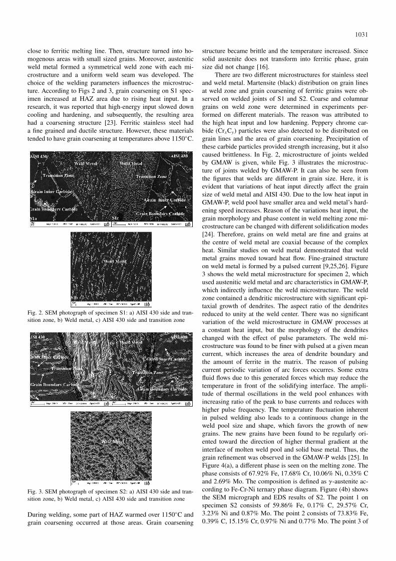
Photographs of internal structure of intersections takenby SEM are illustrated in Fig. 2 GMAW (S1) and Fig. 3GMAW-P (S2). When welded joints of specimens were sub-jected to metallographic examination, the weld seam was ob-served homogeneous in appearance and ferritic stainless steelside and austenitic stainless steel weld metal exhibited differ-ent aspects. Grain coarsening was developed on welded joint
1031
close to ferritic melting line. Then, structure turned into ho-mogenous areas with small sized grains. Moreover, austeniticweld metal formed a symmetrical weld zone with each mi-crostructure and a uniform weld seam was developed. Thechoice of the welding parameters influences the microstruc-ture. According to Figs 2 and 3, grain coarsening on S1 spec-imen increased at HAZ area due to rising heat input. In aresearch, it was reported that high-energy input slowed downcooling and hardening, and subsequently, the resulting areahad a coarsening structure [23]. Ferritic stainless steel hada fine grained and ductile structure. However, these materialstended to have grain coarsening at temperatures above 1150◦C.
Fig. 2. SEM photograph of specimen S1: a) AISI 430 side and tran-sition zone, b) Weld metal, c) AISI 430 side and transition zone
Fig. 3. SEM photograph of specimen S2: a) AISI 430 side and tran-sition zone, b) Weld metal, c) AISI 430 side and transition zone
During welding, some part of HAZ warmed over 1150◦C andgrain coarsening occurred at those areas. Grain coarsening
structure became brittle and the temperature increased. Sincesolid austenite does not transform into ferritic phase, grainsize did not change [16].
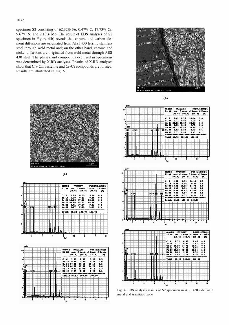
There are two different microstructures for stainless steeland weld metal. Martensite (black) distribution on grain linesat weld zone and grain coarsening of ferritic grains were ob-served on welded joints of S1 and S2. Coarse and columnargrains on weld zone were determined in experiments per-formed on different materials. The reason was attributed tothe high heat input and low hardening. Peppery chrome car-bide (CrxCy) particles were also detected to be distributed ongrain lines and the area of grain coarsening. Precipitation ofthese carbide particles provided strength increasing, but it alsocaused brittleness. In Fig. 2, microstructure of joints weldedby GMAW is given, while Fig. 3 illustrates the microstruc-ture of joints welded by GMAW-P. It can also be seen fromthe figures that welds are different in grain size. Here, it isevident that variations of heat input directly affect the grainsize of weld metal and AISI 430. Due to the low heat input inGMAW-P, weld pool have smaller area and weld metal’s hard-ening speed increases. Reason of the variations heat input, thegrain morphology and phase content in weld melting zone mi-crostructure can be changed with different solidification modes[24]. Therefore, grains on weld metal are fine and grains atthe centre of weld metal are coaxial because of the complexheat. Similar studies on weld metal demonstrated that weldmetal grains moved toward heat flow. Fine-grained structureon weld metal is formed by a pulsed current [9,25,26]. Figure3 shows the weld metal microstructure for specimen 2, whichused austenitic weld metal and arc characteristics in GMAW-P,which indirectly influence the weld microstructure. The weldzone contained a dendritic microstructure with significant epi-taxial growth of dendrites. The aspect ratio of the dendritesreduced to unity at the weld center. There was no significantvariation of the weld microstructure in GMAW processes ata constant heat input, but the morphology of the dendriteschanged with the effect of pulse parameters. The weld mi-crostructure was found to be finer with pulsed at a given meancurrent, which increases the area of dendrite boundary andthe amount of ferrite in the matrix. The reason of pulsingcurrent periodic variation of arc forces occurres. Some extrafluid flows due to this generated forces which may reduce thetemperature in front of the solidifying interface. The ampli-tude of thermal oscillations in the weld pool enhances withincreasing ratio of the peak to base currents and reduces withhigher pulse frequency. The temperature fluctuation inherentin pulsed welding also leads to a continuous change in theweld pool size and shape, which favors the growth of newgrains. The new grains have been found to be regularly ori-ented toward the direction of higher thermal gradient at theinterface of molten weld pool and solid base metal. Thus, thegrain refinement was observed in the GMAW-P welds [25]. InFigure 4(a), a different phase is seen on the melting zone. Thephase consists of 67.92% Fe, 17.68% Cr, 10.06% Ni, 0.35% Cand 2.69% Mo. The composition is defined as γ-austenite ac-cording to Fe-Cr-Ni ternary phase diagram. Figure (4b) showsthe SEM micrograph and EDS results of S2. The point 1 onspecimen S2 consists of 59.86% Fe, 0.17% C, 29.57% Cr,3.23% Ni and 0.87% Mo. The point 2 consists of 73.83% Fe,0.39% C, 15.15% Cr, 0.97% Ni and 0.77% Mo. The point 3 of
1032
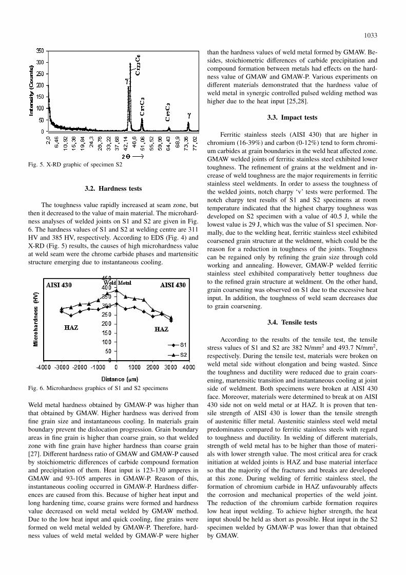
specimen S2 consisting of 62.32% Fe, 0.47% C, 17.73% Cr,9.67% Ni and 2.18% Mo. The result of EDS analyses of S2specimen in Figure 4(b) reveals that chrome and carbon ele-ment diffusions are originated from AISI 430 ferritic stainlesssteel through weld metal and; on the other hand, chrome andnickel diffusions are originated from weld metal through AISI430 steel. The phases and compounds occurred in specimenswas determined by X-RD analyses. Results of X-RD analysesshow that Cr23C6, austenite and Cr7C3 compounds are formed.Results are illustrated in Fig. 5.
Fig. 4. EDS analyses results of S2 specimen in AISI 430 side, weldmetal and transition zone
1033
Fig. 5. X-RD graphic of specimen S2
3.2. Hardness tests
The toughness value rapidly increased at seam zone, butthen it decreased to the value of main material. The microhard-ness analyses of welded joints on S1 and S2 are given in Fig.6. The hardness values of S1 and S2 at welding centre are 311HV and 385 HV, respectively. According to EDS (Fig. 4) andX-RD (Fig. 5) results, the causes of high microhardness valueat weld seam were the chrome carbide phases and martensiticstructure emerging due to instantaneous cooling.
Fig. 6. Microhardness graphics of S1 and S2 specimens
Weld metal hardness obtained by GMAW-P was higher thanthat obtained by GMAW. Higher hardness was derived fromfine grain size and instantaneous cooling. In materials grainboundary prevent the dislocation progression. Grain boundaryareas in fine grain is higher than coarse grain, so that weldedzone with fine grain have higher hardness than coarse grain[27]. Different hardness ratio of GMAW and GMAW-P causedby stoichiometric differences of carbide compound formationand precipitation of them. Heat input is 123-130 amperes inGMAW and 93-105 amperes in GMAW-P. Reason of this,instantaneous cooling occurred in GMAW-P. Hardness differ-ences are caused from this. Because of higher heat input andlong hardening time, coarse grains were formed and hardnessvalue decreased on weld metal welded by GMAW method.Due to the low heat input and quick cooling, fine grains wereformed on weld metal welded by GMAW-P. Therefore, hard-ness values of weld metal welded by GMAW-P were higher
than the hardness values of weld metal formed by GMAW. Be-sides, stoichiometric differences of carbide precipitation andcompound formation between metals had effects on the hard-ness value of GMAW and GMAW-P. Various experiments ondifferent materials demonstrated that the hardness value ofweld metal in synergic controlled pulsed welding method washigher due to the heat input [25,28].
3.3. Impact tests
Ferritic stainless steels (AISI 430) that are higher inchromium (16-39%) and carbon (0-12%) tend to form chromi-um carbides at grain boundaries in the weld heat affected zone.GMAW welded joints of ferritic stainless steel exhibited lowertoughness. The refinement of grains at the weldment and in-crease of weld toughness are the major requirements in ferriticstainless steel weldments. In order to assess the toughness ofthe welded joints, notch charpy ‘v’ tests were performed. Thenotch charpy test results of S1 and S2 specimens at roomtemperature indicated that the highest charpy toughness wasdeveloped on S2 specimen with a value of 40.5 J, while thelowest value is 29 J, which was the value of S1 specimen. Nor-mally, due to the welding heat, ferritic stainless steel exhibitedcoarsened grain structure at the weldment, which could be thereason for a reduction in toughness of the joints. Toughnesscan be regained only by refining the grain size through coldworking and annealing. However, GMAW-P welded ferriticstainless steel exhibited comparatively better toughness dueto the refined grain structure at weldment. On the other hand,grain coarsening was observed on S1 due to the excessive heatinput. In addition, the toughness of weld seam decreases dueto grain coarsening.
3.4. Tensile tests
According to the results of the tensile test, the tensilestress values of S1 and S2 are 382 N/mm2 and 493.7 N/mm2,respectively. During the tensile test, materials were broken onweld metal side without elongation and being wasted. Sincethe toughness and ductility were reduced due to grain coars-ening, martensitic transition and instantaneous cooling at jointside of weldment. Both specimens were broken at AISI 430face. Moreover, materials were determined to break at on AISI430 side not on weld metal or at HAZ. It is proven that ten-sile strength of AISI 430 is lower than the tensile strengthof austenitic filler metal. Austenitic stainless steel weld metalpredominates compared to ferritic stainless steels with regardto toughness and ductility. In welding of different materials,strength of weld metal has to be higher than those of materi-als with lower strength value. The most critical area for crackinitiation at welded joints is HAZ and base material interfaceso that the majority of the fractures and breaks are developedat this zone. During welding of ferritic stainless steel, theformation of chromium carbide in HAZ unfavourably affectsthe corrosion and mechanical properties of the weld joint.The reduction of the chromium carbide formation requireslow heat input welding. To achieve higher strength, the heatinput should be held as short as possible. Heat input in the S2specimen welded by GMAW-P was lower than that obtainedby GMAW.
1034
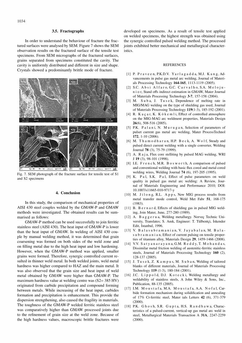
3.5. Fractographs
In order to understand the behaviour of fracture the frac-tured surfaces were analysed by SEM. Figure 7 shows the SEMobservation results on the fractured surface of the tensile testspecimens. From SEM micrographs of the fractured surfaces,grains separated from specimens constituted the cavity. Thecavity is uniformly distributed and different in size and shape.Crystals showed a predominantly brittle mode of fracture.
Fig. 7. SEM photograph of the fracture surface for tensile test of S1and S2 specimens
4. Conclusion
In this study, the comparison of mechanical properties ofAISI 430 steel couples welded by the GMAW-P and GMAWmethods were investigated. The obtained results can be sum-marised as follows:
GMAW-P method can be used successfully to join ferriticstainless steel (AISI 430). The heat input of GMAW-P is lowerthan the heat input of GMAW. In welding of AISI 430 cou-ple by manual welding method, it was determined that graincoarsening was formed on both sides of the weld zone andon filling metal due to the high heat input and low hardening.However, when the GMAW-P method was applied, smallergrains were formed. Therefore, synergic controlled current re-sulted in thinner weld metal. In both welded joints, weld metalhardness was higher compared to HAZ and the main metal. Itwas also observed that the grain size and heat input of weldmetal obtained by GMAW were higher than GMAW-P. Themaximum hardness value at welding centre was (S2= 385 HV)originated from carbide precipitation and compound formingbetween metals. While increasing of the heat input, carbidesformation and precipitation is enhancement. This provide thedispersion strengthening, also caused the fragility in materials.The toughness of the GMAW-P welded ferritic stainless steelwas comparatively higher than GMAW processed joints dueto the refinement of grain size at the weld zone. Because ofthe high hardness values, macroscopic brittle fractures were
developed on specimens. As a result of tensile test appliedon welded specimens, the highest strength was obtained usingthe synergic controlled pulsed welding method. The processedjoints exhibited better mechanical and metallurgical character-istics.
REFERENCES
[1] P. P r a v e e n, P.K.D.V. Ya r l a g a d d a, M.J. K a n g, Ad-vancements in pulse gas metal arc welding, Journal of Materi-als Processing Technology 164-165, 1113-1119 (2005).
[2] S.C. A b s i A l f a r o, G.C. C a r v a l h o, S.A. M e l o j u -n i o r, Stand offs indirect estimation in GMAW, Mater Journalof Materials Processing Technology 3-7, 157-158 (2004).
[3] M. S u b a, J. T u s e k, Dependence of melting rate inMIG/MAG welding on the type of shielding gas used, Journalof Materials Processing Technology 119(1-3), 185-192 (2001).
[4] R. K a c a r, K. K o k e m l i, Effect of controlled atmosphereon the MIG-MAG arc weldment properties, Materials Design26(6), 508-516 (2005).
[5] P.K. P a l a n i, N. M u r u g a n, Selection of parameters ofpulset current gas metal arc welding, Mater ProcessTechnol172, 1-10 (2006).
[6] M. T h a m o d h a r a n, H.P. B e c k, A. W o l f, Steady andpulsed direct current welding with a single converter, WeldingJournal 78 (3), 75-79 (1999).
[7] A. R a j a, Flux core stelliting by pulsed MAG welding, WRIJ 19 (3), 98-101 (1998).
[8] I.E. F r e n c h, M.R. B o s w o r t h, A comparison of pulsedand conventional welding with basic flux cored and metal coredwelding wires, Welding Journal 74 (6), 197-205 (1995).
[9] K. P a l, S.K. P a l, Effect of pulse parameters on weldquality in pulsed gas metal arc welding: A Review, Jour-nal of Materials Engineering and Performance 2010; DOI:10.1007/s11665-010-9717-y
[10] M. J i l o n g, R.L. A p p s, New MIG process results frommetal transfer mode control, Weld Met Fabr 51, 168-175(1983).
[11] B. B e r n a r d, Effects of shielding gas in pulsed MIG weld-ing, Join Mater, June, 277-280 (1989).
[12] A. B a g g e r u a, Welding metallurgy. Norvec Technic Uni-versity, Translates; S. Anık, Engineer: T. Tulbentci, IskenderEdit, Istanbul, 1996.
[13] V. B a l a s u b r a m a n i a n, V. J a y a b a l a n, M. B a l a -s u b r a m a n i a n, Effect of current pulsing on tensile proper-ties of titanium alloy, Materials Design 29, 1459-1466 (2008).
[14] V.V. S a t y a n a r a y a n a, G.M. R e d d y, T. M o h a n d a s,Dissimilar metal friction welding of austenitic-ferritic stainlesssteels, Journal of Materials Processing Technology 160 (2),128-137 (2005).
[15] J. T u s e k, Z. K a m p u s, M. S u b a n, Welding of tailoredblanks of different materials, Journal of Materials ProcessingTechnology 119 (1-3), 180-184 (2001).
[16] J.C. L i p p o l d, D.J. K o t e c k i, Welding metallurgy andweldability of stainless steels, A John Wiley & Sons, Inc.,Publication, 88-135 (2005).
[17] I.M. M o u s t a f a, M.A. M o u s t a f a, A.A. N o f a l, Car-bide formation mechanism during solidification and annealingof 17% Cr-ferritic steel, Mater ials Letters 42 (6), 371-379(2000).
[18] P.K. G h o s h, S.R. G u p t a, H.S. R a n d h a w a, Charac-teristics of a pulsed-current, vertical-up gas metal arc weld insteel, Metallurgical Materials Transaction A 31A, 2247-2259(2000).
1035
[19] J.S. I v a n, B. P a u l o, P.J. M o d e n e s i, High frequencyinduction welding simulating on ferritic stainless steels, Journalof Materials Processing Technology 179 (1-3), 225-230 (2006).
[20] L.M. G o u r d, Principles of welding technology, Third Ed.British Library Cataloguing in Publication Data, London, 4042(1995).
[21] ASTM International Standard E8M-04, Standard test methodsfor tension testing of metallic materials, 2004.
[22] ASTM International Standard E23-06, Standard test methodsfor notched bar impact testing of metallic materials, 2006.
[23] B. G u l e n c, K. D e v e l i, N. K a h r a m a n, A. D u r g u t -l u, Experimental study of the effect of hydrogen in argon as ashielding gas in MIG welding of austenitic stainless steel, In-ternational Journal of Hydrogen Energy 30 (13-14), 1475-1481(2005).
[24] V.S.R. M u r t i, P.D. S r i n i v a s, G.H.D. B a n a d e k i, K.S.R a j u, Effect of heat ınput on the metallurgical properties of
HSLA steel in multi-pass MIG welding, Mater Process Technol37(1-4), 723-729 (1993).
[25] G. L o t h o n g k u m, E. V i y a n i t, P. B h a n d h u b a n y -o n g, Study on the effects of pulsed TIG welding parameterson delta-ferrite content, shape factor and bead quality in orbitalwelding of AISI 316L stainless steel plate, Journal of MaterialsProcessing Technology 110 (2), 233-238 (2001).
[26] A. D u r g u t l u, Experimental investigation of the effect of hy-drogen in argon as a shielding gas on TIG welding of austeniticstainless steel, Materials Design 25 (l), 19-23 (2004).
[27] W.F. S m i t h, Material science and engineering, Third Edi-tion, Mc Graw-Hill Companies, 271-278 (2004).
[28] M.V. S u r e s h, B.V. K r i s h n a, P. V e n u g o p a l, K.P r a s a d R a o, Effect of pulse frequency in gas tungsten arcwelding of powder metallurgical performs, Science and Tech-nology of welding and joining 9 (4), 362-368 (2004).
Received: 10 April 2012.