DATASHEET - RGB Automatyka · SIEMENS. YOUR PARTNER IN ... Figure 1: PAM Simatic S5 System...
17
RGB ELEKTRONIKA AGACIAK CIACIEK SPÓŁKA JAWNA Jana Dlugosza 2-6 Street 51-162 Wrocław Poland [email protected] +48 71 325 15 05 www.rgbautomatyka.pl www.rgbelektronika.pl DATASHEET www.rgbautomatyka.pl www.rgbelektronika.pl OTHER SYMBOLS: 6ES5491-0LB11 6ES54910LB11, 6ES5491 0LB11, 6ES5491-0LB11 SIEMENS
-
Upload
duongkhanh -
Category
Documents
-
view
247 -
download
0
Transcript of DATASHEET - RGB Automatyka · SIEMENS. YOUR PARTNER IN ... Figure 1: PAM Simatic S5 System...
RGB ELEKTRONIKA AGACIAK CIACIEKSPÓŁKA JAWNA Jana Dlugosza 2-6 Street51-162 WrocławPoland
[email protected] +48 71 325 15 05
www.rgbautomatyka.pl
www.rgbelektronika.pl
DATASHEET
www.rgbautomatyka.plwww.rgbelektronika.pl
OTHER SYMBOLS:
6ES5491-0LB11
6ES54910LB11, 6ES5491 0LB11, 6ES5491-0LB11
SIEMENS
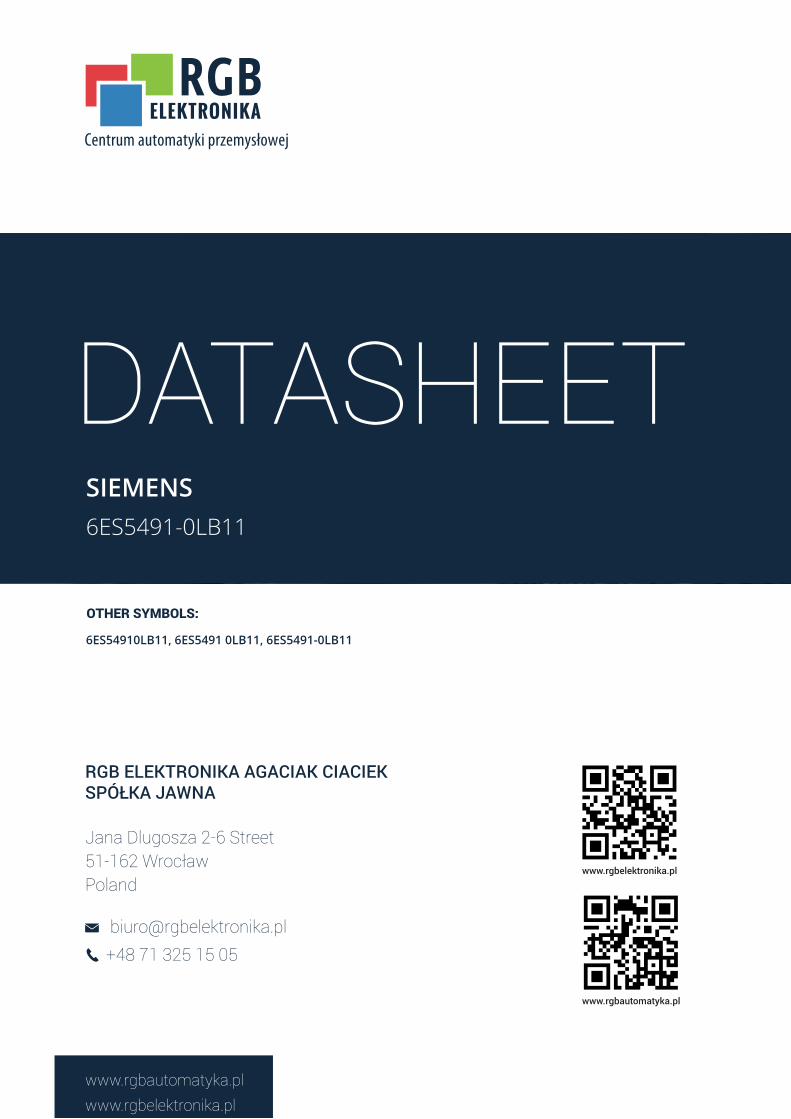
YOUR PARTNER IN MAINTENANCE
At our premises in Wrocław, we have a fully equipped servicing facility. Here we perform all the repair works and test each later sold unit. Our trained employees, equipped with a wide variety of tools and having several testing stands at their disposal, are a guarantee of the highest quality service.
OUR SERVICES
ENCODERS
SERVO DRIVERS
LINEAR ENCODERS
SERVO AMPLIFIERS
CNC MACHINES
MOTORS
POWER SUPPLIERS
OPERATOR PANELS
CNC CONTROLS
INDUSTRIAL COMPUTERS
PLC SYSTEMS
Repair this product with RGB ELEKTRONIKA ORDER A DIAGNOSIS �
Buy this product at RGB AUTOMATYKA BUY �
Socapel PAMA Programmable Axes Manager
PAM Simatic S5
Technical Manual
Ordering Number: 006.8006.BRev. 29 May 1996
Doc. No. 006.8006.B/CJO
May 1996by Atlas Copco Controls SA (previously SOCAPEL SA).All rights reserved.
This upgraded and improvedversion replaces all the previous.We reserve the right to amend thisdocument without prior notice anddecline all responsibilities foreventual errors.
Atlas Copco Controls SAEn Montillier 4CH-1303 PENTHAZSwitzerland
Table of Contents
PAM Simatic S5 --- Technical Manual
Doc. No. 006.8006.BRev. 09 October 1997 Page I
TABLE OF CONTENTS
1 PAM SIMATIC S5 TECHNICAL MANUAL---------------------------------------------------------1—1
1.1 Manual Scope -------------------------------------------------------------------------------------------------- 1—1
1.2 Manual Organization and Contents ----------------------------------------------------------------------- 1—1
2 INTRODUCTION ------------------------------------------------------------------------------------------2—1
2.1 General Information------------------------------------------------------------------------------------------ 2—1
2.2 PAM Simatic S5 Architecture ------------------------------------------------------------------------------ 2—2
2.3 SIMATIC Interface Architecture -------------------------------------------------------------------------- 2—3
2.4 Compatibility with Simatic S5 Models and CPUs ------------------------------------------------------ 2—5
3 CONFIGURATIONS--------------------------------------------------------------------------------------3—1
3.1 Configuration for 115U and 135U-------------------------------------------------------------------------- 3—1
3.2 Configuration for 155U -------------------------------------------------------------------------------------- 3—2
3.3 PAM Dual Port Memory Address Configuration------------------------------------------------------- 3—3
3.4 Configuration Examples ------------------------------------------------------------------------------------- 3—4
3.5 Other Switches------------------------------------------------------------------------------------------------- 3—6
4 ANALOG OUTPUTS -------------------------------------------------------------------------------------4—1
PAM Simatic S5 Technical Manual
PAM Simatic S5 --- Technical Manual
Doc. No. 006.8006.BRev. 09 October 1997 Page 1—1
1 PAM SIMATIC S5 TECHNICAL MANUAL
1.1 MANUAL SCOPE
This manual is intended to serve as a reference for individuals who will be using the PAMSimatic S5. It provides details on the hardware aspects of the Simatic interface for PAM.
The scope of this manual is limited to the PAM Simatic S5. For a complete listing of all technicalpublications covering PAM and its associated peripherals (i.e. ST1, Smart I-O, VME Bus Master,etc..), refer to the Technical Publications Overview in the PAM User’s Manual (p/n 006.8017.A)and to the Technical Documentation, Available Manuals list (p/n 080.8010).
1.2 MANUAL ORGANIZATION AND CONTENTS
This manual is organized into four chapters. The following is a summary of the manual contentsby chapter:
Chapter 1 Description of manual organization and contents
Chapter 2 PAM Simatic S5 description
Chapter 3 PAM Simatic S5 configuration
Chapter 4 Analog outputs description
Introduction
PAM Simatic S5 --- Technical Manual
Doc. No. 006.8006.BRev. 09 October 1997 Page 2—1
2 INTRODUCTION
2.1 GENERAL INFORMATION
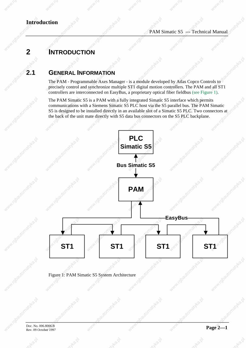
The PAM - Programmable Axes Manager - is a module developed by Atlas Copco Controls toprecisely control and synchronize multiple ST1 digital motion controllers. The PAM and all ST1controllers are interconnected on EasyBus, a proprietary optical fiber fieldbus (see Figure 1).
The PAM Simatic S5 is a PAM with a fully integrated Simatic S5 interface which permitscommunications with a Siemens Simatic S5 PLC host via the S5 parallel bus. The PAM SimaticS5 is designed to be installed directly in an available slot of a Simatic S5 PLC. Two connectors atthe back of the unit mate directly with S5 data bus connectors on the S5 PLC backplane.
PLC Simatic S5
PAM
ST1 ST1 ST1 ST1
Bus Si matic S5
EasyBus
Figure 1: PAM Simatic S5 System Architecture
IntroductionPAM Simatic S5 --- Technical Manual
Doc. No. 006.8006.BRev. 09 October 1997Page: 2—2
2.2 PAM SIMATIC S5 ARCHITECTURE
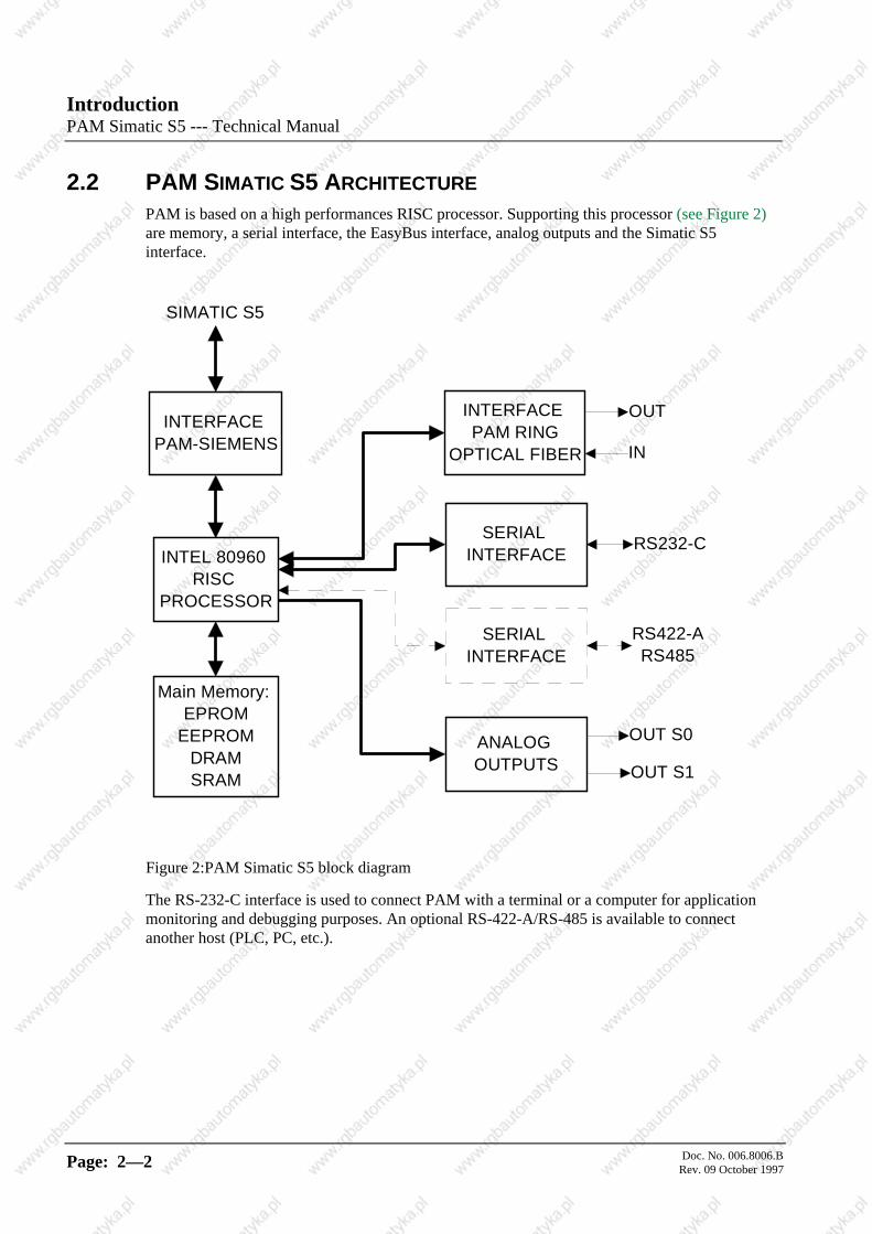
PAM is based on a high performances RISC processor. Supporting this processor (see Figure 2)are memory, a serial interface, the EasyBus interface, analog outputs and the Simatic S5interface.
INTERFACE PAM-SIEMENS
INTEL 80960 RISC
PROCESSOR
Main Memory: EPROM
EEPROM DRAM SRAM
INTERFACE PAM RING
OPTICAL FIBER
SERIAL INTERFACE
ANALOG OUTPUTS
SIMATIC S5
OUT
IN
RS232-C
RS422-A RS485
OUT S0
OUT S1
SERIAL INTERFACE
Figure 2:PAM Simatic S5 block diagram
The RS-232-C interface is used to connect PAM with a terminal or a computer for applicationmonitoring and debugging purposes. An optional RS-422-A/RS-485 is available to connectanother host (PLC, PC, etc.).
Introduction
PAM Simatic S5 --- Technical Manual
Doc. No. 006.8006.BRev. 09 October 1997 Page 2—3
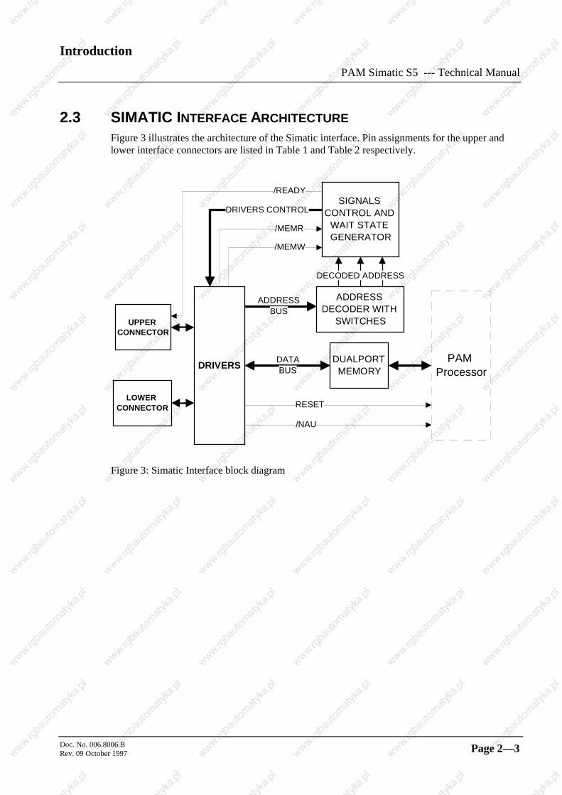
2.3 SIMATIC INTERFACE ARCHITECTURE
Figure 3 illustrates the architecture of the Simatic interface. Pin assignments for the upper andlower interface connectors are listed in Table 1 and Table 2 respectively.
ADDRESS DECODER WITH
SWITCHES
LOWER CONNECTOR
DUALPORT MEMORY
UPPER CONNECTOR
DATA BUS
ADDRESS BUS
SIGNALS CONTROL AND
WAIT STATE GENERATOR
DRIVERS CONTROL
/READY
/MEMR
/MEMW
/NAU
DECODED ADDRESS
RESET
DRIVERSPAM
Processor
Figure 3: Simatic Interface block diagram
IntroductionPAM Simatic S5 --- Technical Manual
Doc. No. 006.8006.BRev. 09 October 1997Page: 2—4
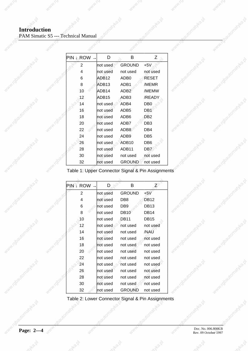
PIN ↓ ROW → D B Z
2 not used GROUND +5V
4 not used not used not used
6 ADB12 ADB0 RESET
8 ADB13 ADB1 /MEMR
10 ADB14 ADB2 /MEMW
12 ADB15 ADB3 /READY
14 not used ADB4 DB0
16 not used ADB5 DB1
18 not used ADB6 DB2
20 not used ADB7 DB3
22 not used ADB8 DB4
24 not used ADB9 DB5
26 not used ADB10 DB6
28 not used ADB11 DB7
30 not used not used not used
32 not used GROUND not used
Table 1: Upper Connector Signal & Pin Assignments
PIN ↓ ROW → D B Z
2 not used GROUND +5V
4 not used DB8 DB12
6 not used DB9 DB13
8 not used DB10 DB14
10 not used DB11 DB15
12 not used not used not used
14 not used not used /NAU
16 not used not used not used
18 not used not used not used
20 not used not used not used
22 not used not used not used
24 not used not used not used
26 not used not used not used
28 not used not used not used
30 not used not used not used
32 not used GROUND not used
Table 2: Lower Connector Signal & Pin Assignments
Introduction
PAM Simatic S5 --- Technical Manual
Doc. No. 006.8006.BRev. 09 October 1997 Page 2—5
i The comment "not used" mean that the SIMATIC S5 signal is not used by the PAM.
! The PAM system needs in all cases both the upper and lower connectors forpower distribution purposes.
2.4 COMPATIBILITY WITH SIMATIC S5 MODELS AND CPUS
Communication compatibility between the PAM SIMATIC and a number of Simatic S5 modelswith different CPUs has been verified by test. Siemens specifications for other CPUs indicatecompatibility. Refer to Table 3 for a summary of current compatibility information.
PLC MODEL →STATUS ↓
115U/135U 155U
TESTED WITH (CPU) 941,944, 944B 946/947
SIEMENS SPECS.INDICATECOMPATIBILITY WITH(CPU)
942,943,941B,942B,943B 948
Table 3: Siemens S5 Compatibility
STOPSIEMENS documentation, states the new 945 CPU is compatible with older CPUs;however, ACC has neither tested nor verified compatibility with the 945.
Configuration
PAM Simatic S5 --- Technical Manual
Doc. No. 006.8006.BRev. 09 October 1997 Page 3—1
3 CONFIGURATIONS
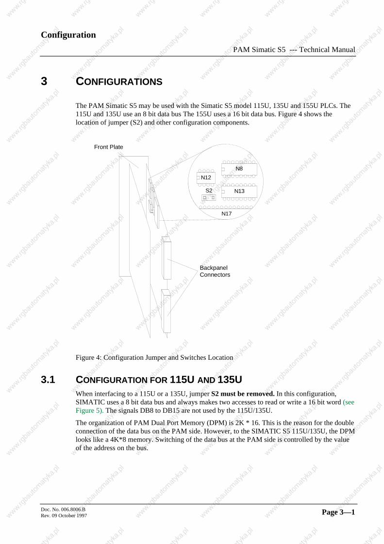
The PAM Simatic S5 may be used with the Simatic S5 model 115U, 135U and 155U PLCs. The115U and 135U use an 8 bit data bus The 155U uses a 16 bit data bus. Figure 4 shows thelocation of jumper (S2) and other configuration components.
N13
N12
S2
N17
N8
Front Plate
BackpanelConnectors
Figure 4: Configuration Jumper and Switches Location
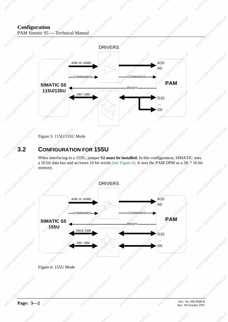
3.1 CONFIGURATION FOR 115U AND 135UWhen interfacing to a 115U or a 135U, jumper S2 must be removed. In this configuration,SIMATIC uses a 8 bit data bus and always makes two accesses to read or write a 16 bit word (seeFigure 5). The signals DB8 to DB15 are not used by the 115U/135U.
The organization of PAM Dual Port Memory (DPM) is 2K * 16. This is the reason for the doubleconnection of the data bus on the PAM side. However, to the SIMATIC S5 115U/135U, the DPMlooks like a 4K*8 memory. Switching of the data bus at the PAM side is controlled by the valueof the address on the bus.
ConfigurationPAM Simatic S5 --- Technical Manual
Doc. No. 006.8006.BRev. 09 October 1997Page: 3—2
A15 A0
PAM
D15 .. D0
SIMATIC S5 115U/135U
DRIVERS
COMMANDS COMMANDS
ADB 15..ADB0
DB7..DB0
READY
Figure 5: 115U/135U Mode
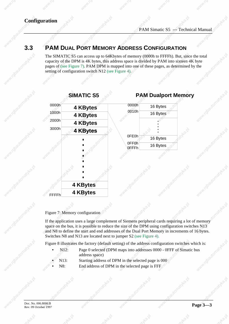
3.2 CONFIGURATION FOR 155UWhen interfacing to a 155U, jumper S2 must be installed. In this configuration, SIMATIC usesa 16 bit data bus and accesses 16 bit words (see Figure 6). It sees the PAM DPM as a 2K * 16 bitmemory.
A15 A0
PAM
D15 .. D0
SIMATIC S5 155U
DRIVERS
COMMANDS COMMANDS
ADB 15..ADB0
DB15..DB8
READY
DB7..DB0
Figure 6: 155U Mode
Configuration
PAM Simatic S5 --- Technical Manual
Doc. No. 006.8006.BRev. 09 October 1997 Page 3—3
3.3 PAM DUAL PORT MEMORY ADDRESS CONFIGURATION
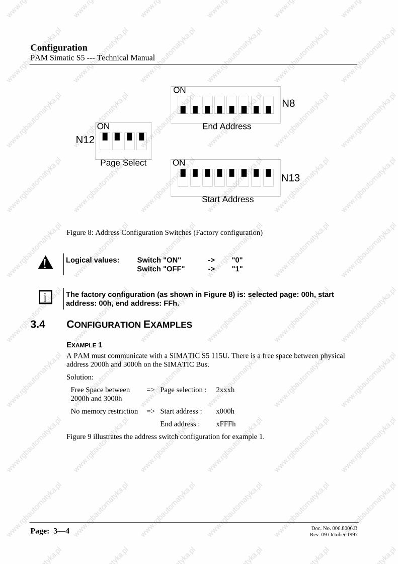
The SIMATIC S5 can access up to 64Kbytes of memory (0000h to FFFFh). But, since the totalcapacity of the DPM is 4K bytes, this address space is divided by PAM into sixteen 4K bytepages of (see Figure 7). PAM DPM is mapped into one of these pages, as determined by thesetting of configuration switch N12 (see Figure 4).
SIMATIC S5 PAM Dual port Memory
4 KBytes4 KBytes4 KBytes4 KBytes
4 KBytes
4 KBytes
4 KBytes
0000h
FFFFh
0000h
0FFFh
1000h
2000h
3000h
0010h
0FE0h
0FF0h
16 Bytes
16 Bytes
16 Bytes
16 Bytes
Figure 7: Memory configuration
If the application uses a large complement of Siemens peripheral cards requiring a lot of memoryspace on the bus, it is possible to reduce the size of the DPM using configuration switches N13and N8 to define the start and end addresses of the Dual Port Memory in increments of 16 bytes.Switches N8 and N13 are located next to jumper S2 (see Figure 4).
Figure 8 illustrates the factory (default setting) of the address configuration switches which is:
• N12: Page 0 selected (DPM maps into addresses 0000 - 0FFF of Simatic bus address space)
• N13: Starting address of DPM in the selected page is 000• N8: End address of DPM in the selected page is FFF
ConfigurationPAM Simatic S5 --- Technical Manual
Doc. No. 006.8006.BRev. 09 October 1997Page: 3—4
ON
ON
ON
N12
N8
N13
End Address
Start Address
Page Select
Figure 8: Address Configuration Switches (Factory configuration)
! Logical values: Switch "ON" -> "0"Switch "OFF" -> "1"
i The factory configuration (as shown in Figure 8) is: selected page: 00h, startaddress: 00h, end address: FFh.
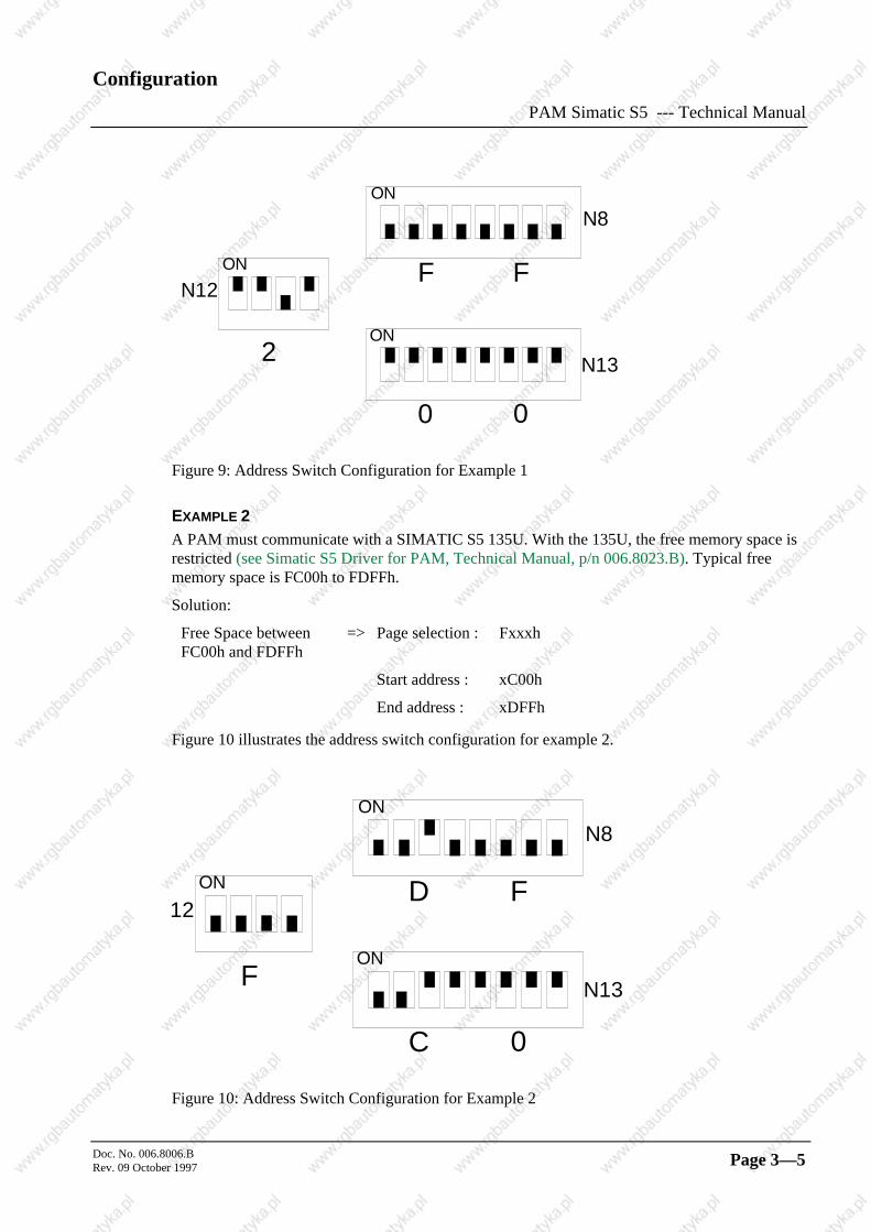
3.4 CONFIGURATION EXAMPLES
EXAMPLE 1A PAM must communicate with a SIMATIC S5 115U. There is a free space between physicaladdress 2000h and 3000h on the SIMATIC Bus.
Solution:
Free Space between2000h and 3000h
=> Page selection : 2xxxh
No memory restriction => Start address : x000h
End address : xFFFh
Figure 9 illustrates the address switch configuration for example 1.
Configuration
PAM Simatic S5 --- Technical Manual
Doc. No. 006.8006.BRev. 09 October 1997 Page 3—5
ON
ON
ON
N12
N8
N13
F
0
2
F
0
Figure 9: Address Switch Configuration for Example 1
EXAMPLE 2A PAM must communicate with a SIMATIC S5 135U. With the 135U, the free memory space isrestricted (see Simatic S5 Driver for PAM, Technical Manual, p/n 006.8023.B). Typical freememory space is FC00h to FDFFh.
Solution:
Free Space betweenFC00h and FDFFh
=> Page selection : Fxxxh
Start address : xC00h
End address : xDFFh
Figure 10 illustrates the address switch configuration for example 2.
ON
ON
ON
12
N8
N13
D
C
F
F
0
Figure 10: Address Switch Configuration for Example 2
ConfigurationPAM Simatic S5 --- Technical Manual
Doc. No. 006.8006.BRev. 09 October 1997Page: 3—6
3.5 OTHER SWITCHES
All other switches of the SIMATIC S5 interface board, from S3 to S15, and all switches of theCPU board are configured at the factory and may not be modified.
Analog outputs
PAM Simatic S5 --- Technical Manual
Doc. No. 006.8006.BRev. 09 October 1997 Page 4—1
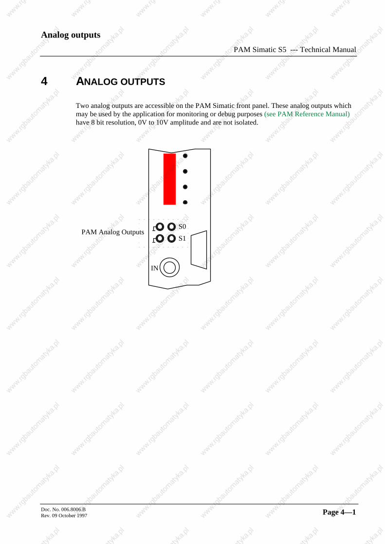
4 ANALOG OUTPUTS
Two analog outputs are accessible on the PAM Simatic front panel. These analog outputs whichmay be used by the application for monitoring or debug purposes (see PAM Reference Manual)have 8 bit resolution, 0V to 10V amplitude and are not isolated.
S0
S1PAM Analog Outputs
IN


![Olasonic USB TUJ-S5 C Olasonic b -3 Olasonic 3 ...Olasonic USB TUJ-S5 C Olasonic b -3 Olasonic 3. (Windows7/Vista ) [USB Audio DAO a 4. 5. 7 8 a. USB Audio DAC [USB Audio DAC] USB](https://static.fdocuments.pl/doc/165x107/60097947dee7880da53edd3b/olasonic-usb-tuj-s5-c-olasonic-b-3-olasonic-3-olasonic-usb-tuj-s5-c-olasonic.jpg)