Cracks path growth in turbine blades with TBC under thermo ...
8
T. Sadowski et alii, Frattura ed Integrità Strutturale, 35 (2016) 492-499; DOI: 10.3221/IGF-ESIS.35.55 492 Cracks path growth in turbine blades with TBC under thermo – mechanical cyclic loadings T. Sadowski, P. Golewski Lublin University of Technology, Nadbystrzycka 40, 20-618 Lublin [email protected] ABSTRACT. Blades of combustion turbines are extremely loaded turbojet elements, which transmit operative energy onto a rotor. Experiences of many years indicate, that cracks initiation and propagation in the blades during the operation time can cause destruction not only of the engine, but sometimes an airplane. In high temperature one of the most often occuring interactions in the turbine engine are time variable force fields, caused by non-stationary flowing of an exhaust gas and aerodynamical interaction of the engine elements. The extremal thermo-mechanical loadings initiate gradual degradation process of the blades as a result of fatigue and material creep. More often Thermal Barrier Coatings (TBCs) are applied on the turbine blade surface to provide protection not only against the high temperature but also against aggressive environment. The paper presents the advantages of applying of the TBC layers for increase of the cracks resistance to gradual degradation of the turbine blades. The level of save values of thermo-mechanical loading was estimated. Analysis of critical values of loading leading to crack initiation, further growth and the final blade fragmentation was performed. The most efforted places of the turbine blades were selected and crack paths due to thermo-mechanical cyclic loading were determined. KEYWORDS. Turbine blade; Thermal barrier coating; Finite element method. INTRODUCTION he process of thermo - mechanical fatigue [1-3] takes place in structural elements, working in conditions of cyclic temperature changes and under variable mechanical loadings. This mainly concerns for example: rotors of turbines, turbine blades, heat exchangers, pieces of nuclear reactors, heads, valves and pistons of combustion engines. The observation of thermal fatigue process in construction is usually very complex. It results mainly from the interaction between many factors influencing the fatigue process, and also from the fact that the visual assessment of degradation stage is possible only in the final stage. In high temperature, one of the most often occurring interactions in the turbine engine are the time variable force fields, caused by non-stationary flowing of an exhaust gas and aerodynamic interaction of engine elements. They cause degradation of the blades as a result of fatigue and material creep. Moreover, unfavorable influence of the high temperature on durability of the blades results from intensification of corrosion and erosion processes [4], which change internal structure of the turbine material and gradual degradation of its strength. T
Transcript of Cracks path growth in turbine blades with TBC under thermo ...
T. Sadowski et alii, Frattura ed Integrità Strutturale, 35 (2016) 492-499; DOI: 10.3221/IGF-ESIS.35.55
492
Cracks path growth in turbine blades with TBC under thermo – mechanical cyclic loadings T. Sadowski, P. Golewski Lublin University of Technology, Nadbystrzycka 40, 20-618 Lublin [email protected]
ABSTRACT. Blades of combustion turbines are extremely loaded turbojet elements, which transmit operative energy onto a rotor. Experiences of many years indicate, that cracks initiation and propagation in the blades during the operation time can cause destruction not only of the engine, but sometimes an airplane. In high temperature one of the most often occuring interactions in the turbine engine are time variable force fields, caused by non-stationary flowing of an exhaust gas and aerodynamical interaction of the engine elements. The extremal thermo-mechanical loadings initiate gradual degradation process of the blades as a result of fatigue and material creep. More often Thermal Barrier Coatings (TBCs) are applied on the turbine blade surface to provide protection not only against the high temperature but also against aggressive environment. The paper presents the advantages of applying of the TBC layers for increase of the cracks resistance to gradual degradation of the turbine blades. The level of save values of thermo-mechanical loading was estimated. Analysis of critical values of loading leading to crack initiation, further growth and the final blade fragmentation was performed. The most efforted places of the turbine blades were selected and crack paths due to thermo-mechanical cyclic loading were determined. KEYWORDS. Turbine blade; Thermal barrier coating; Finite element method. INTRODUCTION
he process of thermo - mechanical fatigue [1-3] takes place in structural elements, working in conditions of cyclic temperature changes and under variable mechanical loadings. This mainly concerns for example: rotors of turbines, turbine blades, heat exchangers, pieces of nuclear reactors, heads, valves and pistons of combustion
engines. The observation of thermal fatigue process in construction is usually very complex. It results mainly from the interaction between many factors influencing the fatigue process, and also from the fact that the visual assessment of degradation stage is possible only in the final stage. In high temperature, one of the most often occurring interactions in the turbine engine are the time variable force fields, caused by non-stationary flowing of an exhaust gas and aerodynamic interaction of engine elements. They cause degradation of the blades as a result of fatigue and material creep. Moreover, unfavorable influence of the high temperature on durability of the blades results from intensification of corrosion and erosion processes [4], which change internal structure of the turbine material and gradual degradation of its strength.
T
T. Sadowski et alii, Frattura ed Integrità Strutturale, 35 (2016) 492-499; DOI: 10.3221/IGF-ESIS.35.55
493
To prevent phenomena such as corrosion or thermal shocks, working surfaces of blades are covered by different types of ceramic protective coatings, i.e. Thermal Barrier Coatings (TBC) [3,5,6]. Industrial application found many types of layers obtained by a gas method, contact – gas method, PVD and others. These layers allow for considerable increase of the heat-resistance properties of the blade which is shown in the present paper. Using the thin ceramic layers we can get also extension of the exploitation time. THE FACTORS INFLUENCING THE FATIGUE DURABILITY OF THE TURBINE BLADE
he fatigue durability of the structural elements of the engine is influenced by: - structural factors, - applied technology for manufacturing,
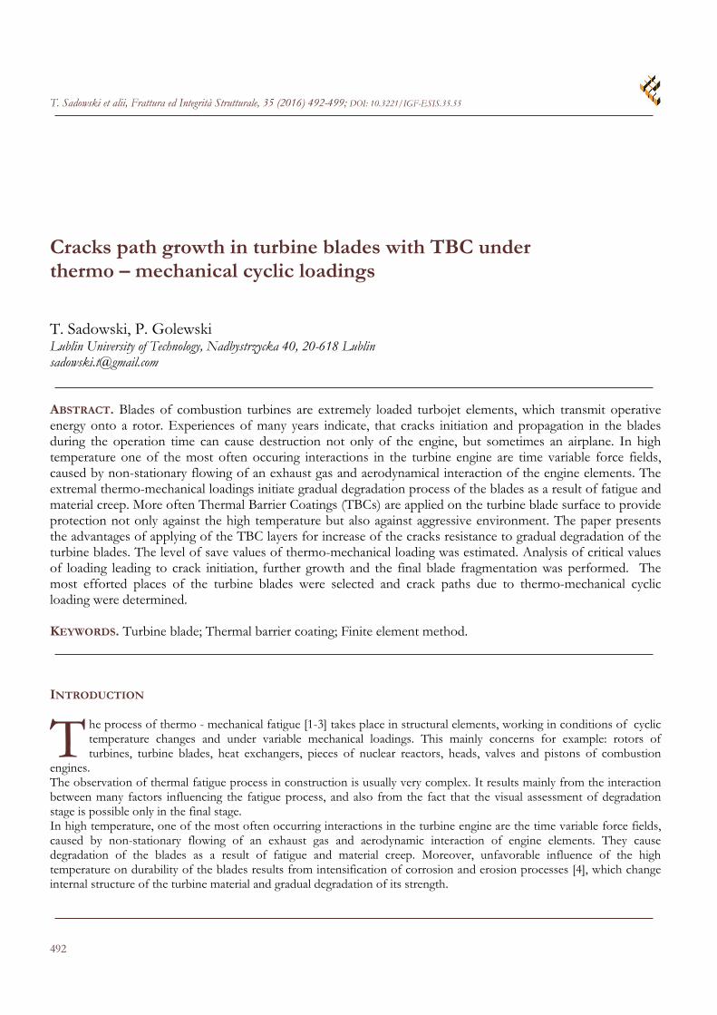
- exploitable conditions. Structural factors include: shape of the elements, their dimensions and local small initial micro-defects (micro-indentations or micro-notches). Manufacturing technology obeys: technological operations for production of the elements, applied processes for improvement of a superficial zone properties. Moreover, the state of the elements surface improved by galvanized covering, grinding and polishing is very important. The exploitable conditions are defined by loading spectrum, pauses of loadings, complexity of loads, the level of operational temperature and the presence of active corrosion environment. The superficial corrosion causes pitting formation and further local roughness. They act as local surface micro-cavities or micro-indentations. Depending on their quantity and dimensions, activity of these defects can be analysed as individual separated indentation (dilute defect density) or when their number is very high these micro-defects can interact (row of defects). Fig. 1 presents an image magnified under SEM in 2 characteristic places of the fatigue and corrosion wear blade: in half its height and in its bottom part. It should be noticed that the blade already reached suitable service life and was excluded from exploitation. The analysis of the state of these 2 points leads to formulation of the following conclusion: the bottom part of the blade is strongly subjected to erosion and corrosion due to the combustion gases. One can notice visible pitting and the micro-indentations. The indentations situated in the bottom part of the blade are the most dangerous, because during exploitation the local maximum of the von Misess stresses takes place. It results from bending of the blade during its work, see Fig. 2.
Figure 1: Surface of the blade.
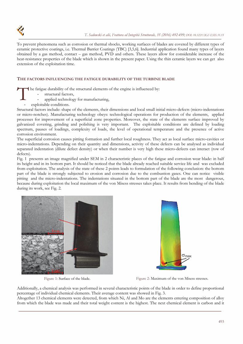
Figure 2: Maximum of the von Misess stresses. Additionally, a chemical analysis was performed in several characteristic points of the blade in order to define proportional percentage of individual chemical elements. Their average content was showed in Fig. 3. Altogether 13 chemical elements were detected, from which Ni, Al and Mo are the elements entering composition of alloy from which the blade was made and their total weight content is the highest. The next chemical element is carbon and it
T
T. Sadowski et alii, Frattura ed Integrità Strutturale, 35 (2016) 492-499; DOI: 10.3221/IGF-ESIS.35.55
494
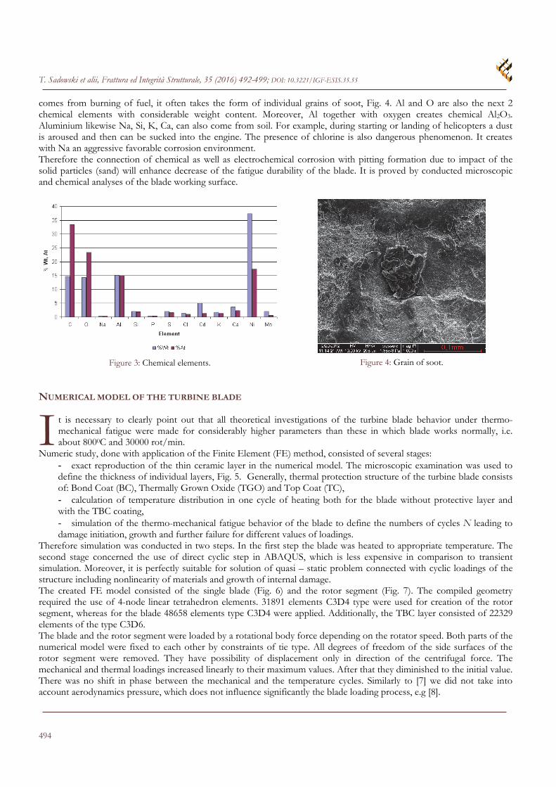
comes from burning of fuel, it often takes the form of individual grains of soot, Fig. 4. Al and O are also the next 2 chemical elements with considerable weight content. Moreover, Al together with oxygen creates chemical Al2O3. Aluminium likewise Na, Si, K, Ca, can also come from soil. For example, during starting or landing of helicopters a dust is aroused and then can be sucked into the engine. The presence of chlorine is also dangerous phenomenon. It creates with Na an aggressive favorable corrosion environment. Therefore the connection of chemical as well as electrochemical corrosion with pitting formation due to impact of the solid particles (sand) will enhance decrease of the fatigue durability of the blade. It is proved by conducted microscopic and chemical analyses of the blade working surface.
Figure 3: Chemical elements.
Figure 4: Grain of soot. NUMERICAL MODEL OF THE TURBINE BLADE
t is necessary to clearly point out that all theoretical investigations of the turbine blade behavior under thermo-mechanical fatigue were made for considerably higher parameters than these in which blade works normally, i.e. about 8000C and 30000 rot/min.
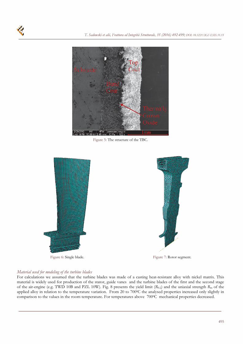
Numeric study, done with application of the Finite Element (FE) method, consisted of several stages: - exact reproduction of the thin ceramic layer in the numerical model. The microscopic examination was used to define the thickness of individual layers, Fig. 5. Generally, thermal protection structure of the turbine blade consists of: Bond Coat (BC), Thermally Grown Oxide (TGO) and Top Coat (TC), - calculation of temperature distribution in one cycle of heating both for the blade without protective layer and with the TBC coating, - simulation of the thermo-mechanical fatigue behavior of the blade to define the numbers of cycles N leading to damage initiation, growth and further failure for different values of loadings.
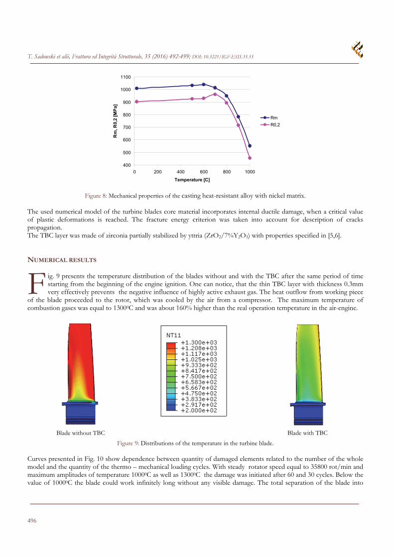
Therefore simulation was conducted in two steps. In the first step the blade was heated to appropriate temperature. The second stage concerned the use of direct cyclic step in ABAQUS, which is less expensive in comparison to transient simulation. Moreover, it is perfectly suitable for solution of quasi – static problem connected with cyclic loadings of the structure including nonlinearity of materials and growth of internal damage. The created FE model consisted of the single blade (Fig. 6) and the rotor segment (Fig. 7). The compiled geometry required the use of 4-node linear tetrahedron elements. 31891 elements C3D4 type were used for creation of the rotor segment, whereas for the blade 48658 elements type C3D4 were applied. Additionally, the TBC layer consisted of 22329 elements of the type C3D6. The blade and the rotor segment were loaded by a rotational body force depending on the rotator speed. Both parts of the numerical model were fixed to each other by constraints of tie type. All degrees of freedom of the side surfaces of the rotor segment were removed. They have possibility of displacement only in direction of the centrifugal force. The mechanical and thermal loadings increased linearly to their maximum values. After that they diminished to the initial value. There was no shift in phase between the mechanical and the temperature cycles. Similarly to [7] we did not take into account aerodynamics pressure, which does not influence significantly the blade loading process, e.g [8].
I
T. Sadowski et alii, Frattura ed Integrità Strutturale, 35 (2016) 492-499; DOI: 10.3221/IGF-ESIS.35.55
495
Figure 5: The structure of the TBC.
Figure 6: Single blade. Figure 7: Rotor segment.
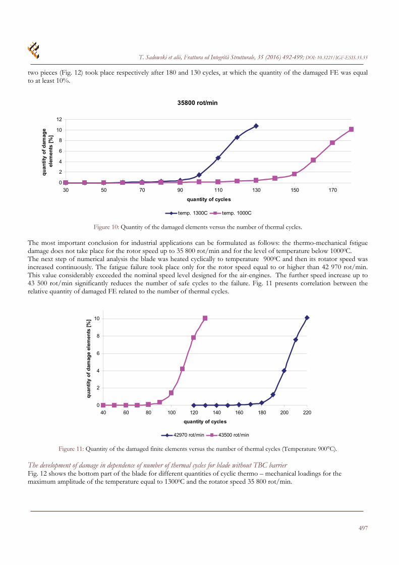
Material used for modeling of the turbine blades For calculations we assumed that the turbine blades was made of a casting heat-resistant alloy with nickel matrix. This material is widely used for production of the stator, guide vanes and the turbine blades of the first and the second stage of the air-engine (e.g. TWD 10B and PZL 10W). Fig. 8 presents the yield limit (R0.2) and the uniaxial strength Rm of the applied alloy in relation to the temperature variation. From 20 to 7000C the analysed properties increased only slightly in comparison to the values in the room temperature. For temperatures above 7000C mechanical properties decreased.
T. Sadowski et alii, Frattura ed Integrità Strutturale, 35 (2016) 492-499; DOI: 10.3221/IGF-ESIS.35.55
496
400
500
600
700
800
900
1000
1100
0 200 400 600 800 1000
Temperature [C]
Rm
, R0
,2 [M
Pa
]Rm
R0,2
Figure 8: Mechanical properties of the casting heat-resistant alloy with nickel matrix. The used numerical model of the turbine blades core material incorporates internal ductile damage, when a critical value of plastic deformations is reached. The fracture energy criterion was taken into account for description of cracks propagation. The TBC layer was made of zirconia partially stabilized by yttria (ZrO2/7%Y2O3) with properties specified in [5,6].
NUMERICAL RESULTS
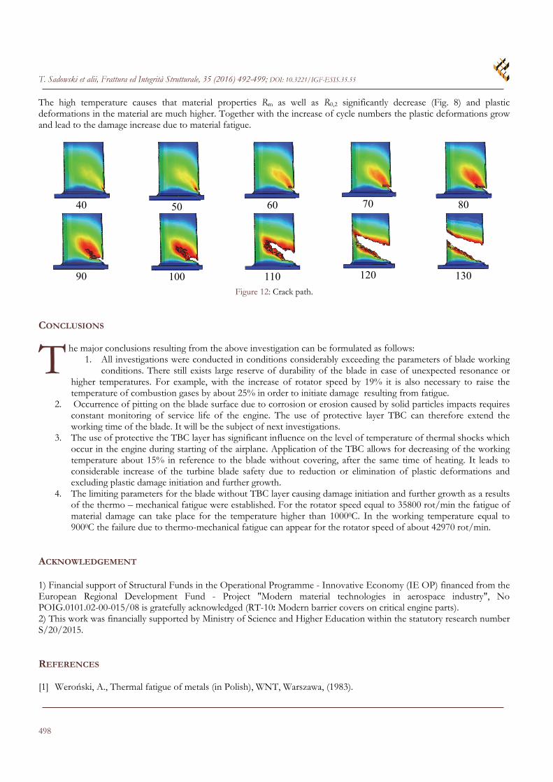
ig. 9 presents the temperature distribution of the blades without and with the TBC after the same period of time starting from the beginning of the engine ignition. One can notice, that the thin TBC layer with thickness 0.3mm very effectively prevents the negative influence of highly active exhaust gas. The heat outflow from working piece
of the blade proceeded to the rotor, which was cooled by the air from a compressor. The maximum temperature of combustion gases was equal to 13000C and was about 160% higher than the real operation temperature in the air-engine.
Blade without TBC
Blade with TBC
Figure 9: Distributions of the temperature in the turbine blade. Curves presented in Fig. 10 show dependence between quantity of damaged elements related to the number of the whole model and the quantity of the thermo – mechanical loading cycles. With steady rotator speed equal to 35800 rot/min and maximum amplitudes of temperature 10000C as well as 13000C the damage was initiated after 60 and 30 cycles. Below the value of 10000C the blade could work infinitely long without any visible damage. The total separation of the blade into
F
T. Sadowski et alii, Frattura ed Integrità Strutturale, 35 (2016) 492-499; DOI: 10.3221/IGF-ESIS.35.55
497
two pieces (Fig. 12) took place respectively after 180 and 130 cycles, at which the quantity of the damaged FE was equal to at least 10%.
35800 rot/min
0
2
4
6
8
10
12
30 50 70 90 110 130 150 170
quantity of cycles
qu
anti
ty o
f d
amag
e el
emen
ts [
%]
temp. 1300C temp. 1000C
Figure 10: Quantity of the damaged elements versus the number of thermal cycles. The most important conclusion for industrial applications can be formulated as follows: the thermo-mechanical fstigue damage does not take place for the rotor speed up to 35 800 rot/min and for the level of temperature below 10000C. The next step of numerical analysis the blade was heated cyclically to temperature 9000C and then its rotator speed was increased continuously. The fatigue failure took place only for the rotor speed equal to or higher than 42 970 rot/min. This value considerably exceeded the nominal speed level designed for the air-engines. The further speed increase up to 43 500 rot/min significantly reduces the number of safe cycles to the failure. Fig. 11 presents correlation between the relative quantity of damaged FE related to the number of thermal cycles.
0
2
4
6
8
10
40 60 80 100 120 140 160 180 200 220
quantity of cycles
qu
anti
ty o
f d
amag
e el
emen
ts [
%]
42970 rot/min 43500 rot/min
Figure 11: Quantity of the damaged finite elements versus the number of thermal cycles (Temperature 900°C).
The development of damage in dependence of number of thermal cycles for blade without TBC barrier Fig. 12 shows the bottom part of the blade for different quantities of cyclic thermo – mechanical loadings for the maximum amplitude of the temperature equal to 13000C and the rotator speed 35 800 rot/min.
T. Sadowski et alii, Frattura ed Integrità Strutturale, 35 (2016) 492-499; DOI: 10.3221/IGF-ESIS.35.55
498
The high temperature causes that material properties Rm as well as R0,2 significantly decrease (Fig. 8) and plastic deformations in the material are much higher. Together with the increase of cycle numbers the plastic deformations grow and lead to the damage increase due to material fatigue.
40
50
60
70
80
90
100
110
120
130
Figure 12: Crack path. CONCLUSIONS
he major conclusions resulting from the above investigation can be formulated as follows: 1. All investigations were conducted in conditions considerably exceeding the parameters of blade working
conditions. There still exists large reserve of durability of the blade in case of unexpected resonance or higher temperatures. For example, with the increase of rotator speed by 19% it is also necessary to raise the temperature of combustion gases by about 25% in order to initiate damage resulting from fatigue.
2. Occurrence of pitting on the blade surface due to corrosion or erosion caused by solid particles impacts requires constant monitoring of service life of the engine. The use of protective layer TBC can therefore extend the working time of the blade. It will be the subject of next investigations.
3. The use of protective the TBC layer has significant influence on the level of temperature of thermal shocks which occur in the engine during starting of the airplane. Application of the TBC allows for decreasing of the working temperature about 15% in reference to the blade without covering, after the same time of heating. It leads to considerable increase of the turbine blade safety due to reduction or elimination of plastic deformations and excluding plastic damage initiation and further growth.
4. The limiting parameters for the blade without TBC layer causing damage initiation and further growth as a results of the thermo – mechanical fatigue were established. For the rotator speed equal to 35800 rot/min the fatigue of material damage can take place for the temperature higher than 10000C. In the working temperature equal to 9000C the failure due to thermo-mechanical fatigue can appear for the rotator speed of about 42970 rot/min.
ACKNOWLEDGEMENT 1) Financial support of Structural Funds in the Operational Programme - Innovative Economy (IE OP) financed from the European Regional Development Fund - Project "Modern material technologies in aerospace industry", No POIG.0101.02-00-015/08 is gratefully acknowledged (RT-10: Modern barrier covers on critical engine parts). 2) This work was financially supported by Ministry of Science and Higher Education within the statutory research number S/20/2015. REFERENCES [1] Weroński, A., Thermal fatigue of metals (in Polish), WNT, Warszawa, (1983).
T
T. Sadowski et alii, Frattura ed Integrità Strutturale, 35 (2016) 492-499; DOI: 10.3221/IGF-ESIS.35.55
499
[2] Cieśla, M., Durablity of superalloy ŻS6U under thermal and mechanical loadings (in Polish), Silesian University of Technology Publishing House, Gliwice, (2009).
[3] Kim, D.-J., Shin, I.-H., Koo, J.-M., Seok, C.-S., Lee, T.-W., Failure mechanisms of coin-type plasma-sprayed thermal barrier coatings with thermal fatigue, Surface & Coatings Technology, 205 (2010) 451 - 458.
[4] Mazur, Z., Garcia-Illescas, R., Porcayo-Calderon, J., Last stage blades failure of a 28 MW geothermal turbine, Engineering Failure Analysis, 16 (2009) 1020 – 1032.
[5] Sadowski, T., Golewski, P., Multidisciplinary analysis of the operational temperature increase of turbine blades in combustion engines by application of the ceramic thermal barrier coatings (TBC), Computational Materials Science, 50 (2011) 1326 - 1335.
[6] Sadowski, T., Golewski, P., The influence of quantity and distribution of cooling channels of turbine elements on level of stresses in the protective layer TBC and the efficiency of cooling, Computational Materials Science, 52 (2012) 293 – 297.
[7] Hou, N.X., Wen, Z.X., Yu, Q.M., Yue, Z.F., Application of a combined high and low cycle fatigue life model on life prediction of SC blade, International Journal of Fatigue, 31 (2009) 616-619.
[8] Moussavi Torshizi, S.E., Yadavar Nikravesh, S.M., Jahangiri, A., Failure analysis of gas turbine generator cooling fan blades, Engineering Failure Analysis, 16 (2009) 1686 – 1695.