A METHOD FOR DETERMINING THE DISTRIBUTION OF LOADS IN...
7
p. 105–111 ISSN 0208-7774 T R I B O L O G I A 1/2017 Bogdan WARDA * , Henryk DUDA ** A METHOD FOR DETERMINING THE DISTRIBUTION OF LOADS IN ROLLING PAIRS IN CYCLOIDAL PLANETARY GEAR METODA WYZNACZANIA ROZKŁADÓW OBCIĄŻEŃ W WĘZŁACH TOCZNYCH OBIEGOWEJ PRZEKŁADNI CYKLOIDALNEJ Key words: cycloidal planetary gear, rolling pairs, distribution of load. Abstract: The power transmission system in the cycloidal planetary gear is created by a serial connection of three rolling pairs: central cylindrical roller bearings, a set of rolling pins in the straight-line mechanism, and cycloidal meshing. The paper presents the numerical method for determining the distribution of forces acting on each rolling pair of this gear. Unlike analytical methods, numerical methods allow one to find that distribution in corrected meshing. Geometrical dimensions used in the equations of balance for the planetary gear transmission Palmgren`s dependences for the deformation line contact were used to calculate forces between co-operating elements. Once the distribution of load is known, one can predict the fatigue life of Cyclo’s gears in rolling pairs. The fatigue of rolling pairs is a very good criterion to optimize geometrical parameters of the power transmission system. Słowa kluczowe: obiegowa przekładnia cykloidalna, węzły toczne, rozkład obciążenia. Streszczenie: Układ przeniesienia mocy obiegowej przekładni cykloidalnej tworzy szeregowe połączenie trzech węzłów tocznych – walcowych łożysk centralnych, zestawu tocznych sworzni w mechanizmie równowodowym oraz zazębienia cykloidalnego. W pracy przedstawiono numeryczną metodę wyznaczania rozkładów sił występu- jących w poszczególnych węzłach tocznych obiegowej przekładni cykloidalnej. W przeciwieństwie do me- tod analitycznych metoda numeryczna pozwala również na znalezienie rozkładów obciążenia dla przekładni cykloidalnej z korygowanym zazębieniem. Zostały wyznaczone wielkości geometryczne, które wykorzy- stano w przedstawionych w artykule równaniach równowagi koła obiegowego przekładni. Do obliczenia sił w stykach współpracujących elementów zastosowano zależność Palmgrena na odkształcenie w styku linio- wym. Znajomość rozkładów obciążenia umożliwia prognozowanie trwałości zmęczeniowej węzłów tocznych obiegowej przekładni cykloidalnej. Trwałość zmęczeniowa węzłów tocznych stanowi bardzo dobre kryterium optymalizacji parametrów geometrycznych przekładni. * Lodz University of Technology, Department of Vehicles and Fundamentals of Machine Design, Żeromskiego 116, 90-924 łódź, Poland, e-mail: [email protected], phone: +48 426312251. ** PhD Student, Lodz University of Technology, Poland, Department of Vehicles and Fundamentals of Machine Design, Żeromskiego 116, 90-924 łódź, Poland. INTRODUCTION Planetary gears are more and more frequently used in driving systems. They have a number of advantages. The cycloidal gear, also known as the Cyclo gear, has the most compact design of all types of gears. The rolling friction necessary in power transmission is provided by applying internal eccentric meshing gear [L. 16]. The Cyclo gear power transmission system consists of a serial connection of three rolling pairs: central cylindrical roller bearings (1), a set of rolling pins in the straight-line mechanism (2), and cycloidal meshing (3) (Fig. 1). Meshing is formed by planetary wheels (usually two, staggered by an angle of 180°) co-operating with a fixed set of z k rollers. Each planetary gear has external teeth in the form of the equidistant of shortened epicycloid. Each planetary wheel has the number of teeth | z s = | i c | (where i c is the gear ratio) [L. 3, 4]. The input torque M h is transmitted via central bearings mounted on the input
Transcript of A METHOD FOR DETERMINING THE DISTRIBUTION OF LOADS IN...
p. 105–111ISSN 0208-7774 T R I B O L O G I A 1/2017
Bogdan WARDA*, Henryk DUDA**
A METHOD FOR DETERMINING THE DISTRIBUTION OF LOADS IN ROLLING PAIRS IN CYCLOIDAL PLANETARY GEAR
METODA WYZNACZANIA ROZKŁADÓW OBCIĄŻEŃ W WĘZŁACH TOCZNYCH OBIEGOWEJ PRZEKŁADNI CYKLOIDALNEJ
Key words: cycloidal planetary gear, rolling pairs, distribution of load.
Abstract: The power transmission system in the cycloidal planetary gear is created by a serial connection of three rolling pairs: central cylindrical roller bearings, a set of rolling pins in the straight-line mechanism, and cycloidal meshing. The paper presents the numerical method for determining the distribution of forces acting on each rolling pair of this gear. Unlike analytical methods, numerical methods allow one to find that distribution in corrected meshing. Geometrical dimensions used in the equations of balance for the planetary gear transmission Palmgren`s dependences for the deformation line contact were used to calculate forces between co-operating elements. Once the distribution of load is known, one can predict the fatigue life of Cyclo’s gears in rolling pairs. The fatigue of rolling pairs is a very good criterion to optimize geometrical parameters of the power transmission system.
Słowa kluczowe: obiegowa przekładnia cykloidalna, węzły toczne, rozkład obciążenia.
Streszczenie: Układ przeniesienia mocy obiegowej przekładni cykloidalnej tworzy szeregowe połączenie trzech węzłów tocznych – walcowych łożysk centralnych, zestawu tocznych sworzni w mechanizmie równowodowym oraz zazębienia cykloidalnego. W pracy przedstawiono numeryczną metodę wyznaczania rozkładów sił występu-jących w poszczególnych węzłach tocznych obiegowej przekładni cykloidalnej. W przeciwieństwie do me-tod analitycznych metoda numeryczna pozwala również na znalezienie rozkładów obciążenia dla przekładni cykloidalnej z korygowanym zazębieniem. Zostały wyznaczone wielkości geometryczne, które wykorzy-stano w przedstawionych w artykule równaniach równowagi koła obiegowego przekładni. Do obliczenia sił w stykach współpracujących elementów zastosowano zależność Palmgrena na odkształcenie w styku linio-wym. Znajomość rozkładów obciążenia umożliwia prognozowanie trwałości zmęczeniowej węzłów tocznych obiegowej przekładni cykloidalnej. Trwałość zmęczeniowa węzłów tocznych stanowi bardzo dobre kryterium optymalizacji parametrów geometrycznych przekładni.
* Lodz University of Technology, Department of Vehicles and Fundamentals of Machine Design, Żeromskiego 116, 90-924 łódź, Poland, e-mail: [email protected], phone: +48 426312251.
** PhD Student, Lodz University of Technology, Poland, Department of Vehicles and Fundamentals of Machine Design, Żeromskiego 116, 90-924 łódź, Poland.
INTRODUCTION
Planetary gears are more and more frequently used in driving systems. They have a number of advantages. The cycloidal gear, also known as the Cyclo gear, has the most compact design of all types of gears. The rolling friction necessary in power transmission is provided by applying internal eccentric meshing gear [L. 16]. The Cyclo gear power transmission system consists of a serial connection of three rolling pairs: central
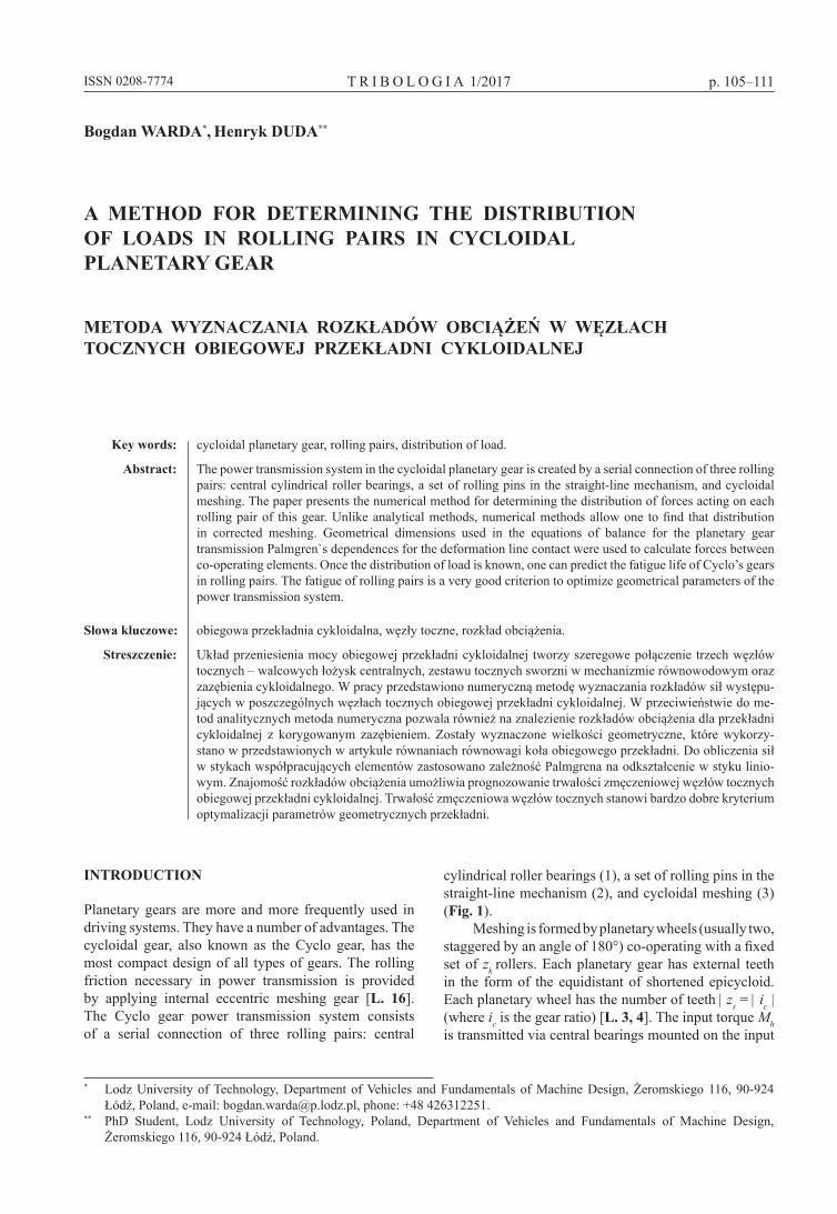
cylindrical roller bearings (1), a set of rolling pins in the straight-line mechanism (2), and cycloidal meshing (3) (Fig. 1).
Meshing is formed by planetary wheels (usually two, staggered by an angle of 180°) co-operating with a fixed set of zk rollers. Each planetary gear has external teeth in the form of the equidistant of shortened epicycloid. Each planetary wheel has the number of teeth | zs = | ic | (where ic is the gear ratio) [L. 3, 4]. The input torque Mh is transmitted via central bearings mounted on the input
106 ISSN 0208-7774 T R I B O L O G I A 1/2017
eccentric shaft to the planetary gears. To output torque, M1 = 2 Mc, from the planetary gears to the output shaft, a straight-line mechanism is used which is formed by the holes in the planetary gears in which pivotal sleeves are rolling. The pivots are rigidly connected to the disc of the output shaft. The third torque M2 loads a set of pivotal sleeves on stationary pins.
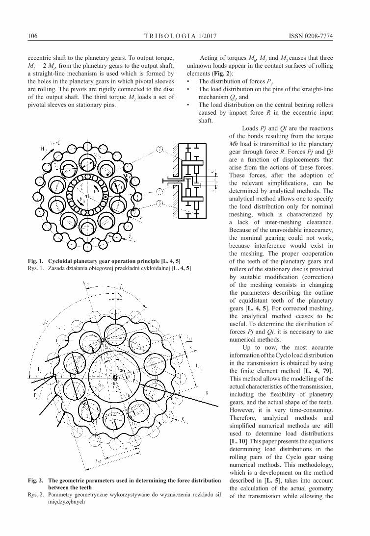
Acting of torques Mh, M1 and M2 causes that three unknown loads appear in the contact surfaces of rolling elements (Fig. 2):• The distribution of forces Pj,• The load distribution on the pins of the straight-line
mechanism Qi, and• The load distribution on the central bearing rollers
caused by impact force R in the eccentric input shaft.
Loads Pj and Qi are the reactions of the bonds resulting from the torque Mh load is transmitted to the planetary gear through force R. Forces Pj and Qi are a function of displacements that arise from the actions of these forces. These forces, after the adoption of the relevant simplifications, can be determined by analytical methods. The analytical method allows one to specify the load distribution only for nominal meshing, which is characterized by a lack of inter-meshing clearance. Because of the unavoidable inaccuracy, the nominal gearing could not work, because interference would exist in the meshing. The proper cooperation of the teeth of the planetary gears and rollers of the stationary disc is provided by suitable modification (correction) of the meshing consists in changing the parameters describing the outline of equidistant teeth of the planetary gears [L. 4, 5]. For corrected meshing, the analytical method ceases to be useful. To determine the distribution of forces Pj and Qi, it is necessary to use numerical methods.
Up to now, the most accurate information of the Cyclo load distribution in the transmission is obtained by using the finite element method [L. 4, 79]. This method allows the modelling of the actual characteristics of the transmission, including the flexibility of planetary gears, and the actual shape of the teeth. However, it is very time-consuming. Therefore, analytical methods and simplified numerical methods are still used to determine load distributions [L. 10]. This paper presents the equations determining load distributions in the rolling pairs of the Cyclo gear using numerical methods. This methodology, which is a development on the method described in [L. 5], takes into account the calculation of the actual geometry of the transmission while allowing the
Fig. 1. Cycloidal planetary gear operation principle [L. 4, 5]Rys. 1. Zasada działania obiegowej przekładni cykloidalnej [L. 4, 5]
Fig. 2. The geometric parameters used in determining the force distribution between the teeth
Rys. 2. Parametry geometryczne wykorzystywane do wyznaczenia rozkładu sił międzyzębnych
107ISSN 0208-7774 T R I B O L O G I A 1/2017
execution of the calculation for a number of data variants in a relatively short time.
FORCE DISTRIBUTION BETWEEN THE TEETH
To determine the force distribution between the teeth in the Cyclo gear, the following simplifying assumptions were adopted:• The deformations of the planetary gear disk do not
exist (except for local deformations in the contacts).• The load is evenly distributed on the planetary
wheels.• The directions of the forces Pj acting on the
individual teeth form a bundle of lines intersecting at the rolling point of the meshing Os (Fig. 2).
• The force in contact of the planetary gear tooth and the co-operating roller j-th of the stationary disc is a function of deflection δsj existing there, resulting from the rotation angle of the planetary gear of angle βs.
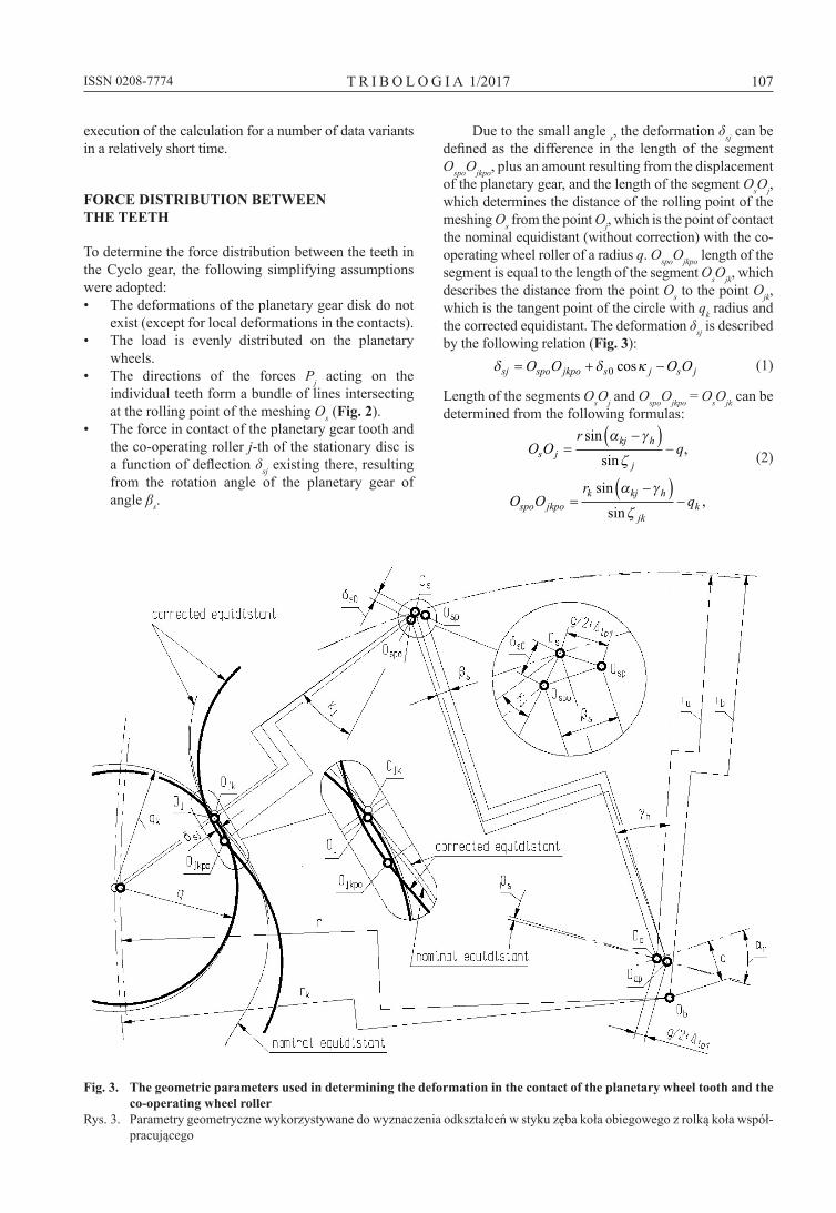
Due to the small angle s, the deformation δsj can be defined as the difference in the length of the segment OspoOjkpo, plus an amount resulting from the displacement of the planetary gear, and the length of the segment OsOj, which determines the distance of the rolling point of the meshing Os from the point Oj, which is the point of contact the nominal equidistant (without correction) with the co-operating wheel roller of a radius q. OspoOjkpo length of the segment is equal to the length of the segment OsOjk, which describes the distance from the point Os to the point Ojk, which is the tangent point of the circle with qk radius and the corrected equidistant. The deformation δsj is described by the following relation (Fig. 3):
δ δ κsj spo jkpo s j s jO O O O= + −0 cos (1)
Length of the segments OsOj and OspoOjkpo = OsOjk can be determined from the following formulas:
O Or
qs jkj h
j=
−( )−
sin
sin,
α γ
ζ (2)
O Or
qspo jkpok kj h
jkk=
−( )−
sin
sin,
α γ
ζ
Fig. 3. The geometric parameters used in determining the deformation in the contact of the planetary wheel tooth and the co-operating wheel roller
Rys. 3. Parametry geometryczne wykorzystywane do wyznaczenia odkształceń w styku zęba koła obiegowego z rolką koła współ-pracującego

108 ISSN 0208-7774 T R I B O L O G I A 1/2017
where
ζα
α
γ
γj
kj h
a kj h
r
r e r=
−( )+ − −( )
arctansin
cos,
(3)
ζα
α
γ
γjk
k kj h
a k kj h
r
r e r=
−( )+ − −( )
arctansin
cos,
αkj k kj z j z= −( ) = …2 1 1 2π / , . (4)
While the lengths of OsOj and OspoOjkpo are a function of the geometrical parameters of the transmission, displacement δs0 and angle κj depend on two variables:• The planetary gear rotation angle βs; and,• The displacement of the planetary gear centre from
point Oa to point Oap arising from the action of the resultant force R in the central bearing:
O O O O ga ap s sp io= = +/ ,2 1∆ (5)where g is the radial clearance in the bearing and ∆io1 is the sum of the deformation of the most loaded roller contacted with the raceways of the centre bearing.
The force R, which determines the size of ∆io1, is a function of the eccentricity e, the action angle of the resultant force in the central bearing αr and torque Mh. For the gear of two planetary wheels, the drive torque is represented by the following formula:
M R eh r= ⋅2 cos .α (6)
Deformations δs0 and the angle κj take the following form:
κ ζβ α
β αj ja s a ap r
a s a ap r
r O Or O O
= −−
−( ) +
arctan
sin coscos sin1
, (7)
δ β α
β α
s a s a ap r
a s a ap r
r O O
r O O
02
2
1= −( ) + { +
+ − }cos sin
sin cos11 2/.
(8)
Assuming that the roller-tooth contact is Hertzian linear, the deformation that is the result of planetary disc angular displacement causes the contact reaction force equal [L. 11, 12]:
P lj sj e= 78000 10 9 8 9δ / / , (9)
where le is a the width of a tooth in the planetary wheel.
To determine the moment resulting from the forces Pj, with respect to Oap, it is necessary to know the arms of the forces Pjx, and Pjy (Fig. 2). These values are described in the following relations:
f r q O Ohj kj h j a ap r= −( ) − +sin sin cos ,α γ ζ α
(10)
f r q e O Ovj kj h j a ap r= −( ) + − +cos cos sin .α γ ζ α (11)
DISTRIBUTION OF FORCES IN STRAIGHT-LINE MECHANISM
The distribution of forces in the straight-line mechanism was determined on the assumption that the force Qi in the contact between i-roller and the proper hole is the function of the deformation δci, as a consequence of both the rotation angle of the planetary gear βs and the rotation angle of the output shaft βc. Similarly, as in the case of the gear teeth contact of the planetary wheel with the co-operating wheel roller, the force Qi is equal to the following:
Q li ci e= 78000 10 9 8 9δ / / . (12)
The deformation δcj can be determined from the relation (Fig. 4):
δci i c sh D D= + −/ / .2 2 (13)
The distance between the geometric centre of the hole in the wheel and the geometric centre of the straight-line mechanism roller is described by the following equation:
h R O O
R e
i w ci si a ap r
w si ci
= −( ) + +{+ −( ) +
sin sin cos
cos cos
ξ ξ α
ξ ξ
2
−− }O Oa ap rsin ,/
α2 1 2
(14)
εξ ξ α
ξ ξiw ci si a ap r
w si ci
R O OR e O
=−( ) +
−( ) + −arctan
sin sin coscos cos aa ap rO sin
,α
(15)
ξ γα β γsi ci s c h= + − +( ) , (16)
ξ γα β γci ci c c h= + − +( ) , (17)
α πci c ci z i z= −( ) = …2 1 1 2/ , , , . (18)
Component action force arms Qix, Qiy with respect to Oap are described in the following relations:
l D h Rhi c i i w si= +( ) +/ sin sin ,2 ε ξ (19)
l D h Rvi c i i w si= +( ) +/ cos cos .2 ε ξ (20)
PLANETARY WHEEL EQUILIBRIUM EQUATIONS
Equilibrium equations of cycloidal planetary gear wheel are as follows:
ΣM f P f P
l Q
Oj
j z
vj j jj
j z
hj j j
i
i z
vi i
ap
k k
c
= + +
+
=
=
=
=
=
=
∑ ∑
∑
1 1
1
sin cosζ ζ
ssin cos ,ε εii
i z
hi i i
c
l Q− ==
=
∑1
0
(21)
109ISSN 0208-7774 T R I B O L O G I A 1/2017
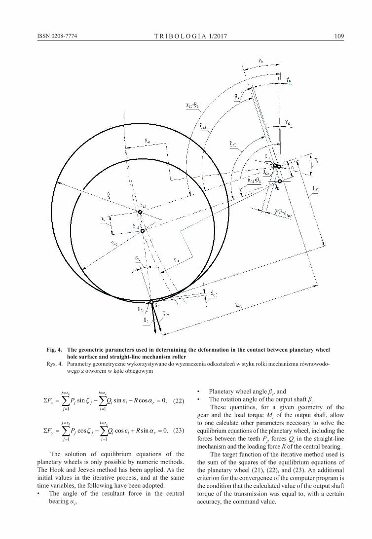
Fig. 4. The geometric parameters used in determining the deformation in the contact between planetary wheel hole surface and straight-line mechanism roller
Rys. 4. Parametry geometryczne wykorzystywane do wyznaczenia odkształceń w styku rolki mechanizmu równowodo-wego z otworem w kole obiegowym
ΣF P Q Rxj
j z
j ji
i z
i i r
k c
= − − ==
=
=
=
∑ ∑1 1
0sin sin cos ,ζ ε α (22)
ΣF P Q Ryj
j z
j ji
i z
i i r
k c
= − + ==
=
=
=
∑ ∑1 1
0cos cos sin .ζ ε α (23)
The solution of equilibrium equations of the planetary wheels is only possible by numeric methods. The Hook and Jeeves method has been applied. As the initial values in the iterative process, and at the same time variables, the following have been adopted:• The angle of the resultant force in the central
bearing αr,
• Planetary wheel angle βs, and• The rotation angle of the output shaft βc.
These quantities, for a given geometry of the gear and the load torque M1 of the output shaft, allow to one calculate other parameters necessary to solve the equilibrium equations of the planetary wheel, including the forces between the teeth Pj, forces Qi in the straight-line mechanism and the loading force R of the central bearing.
The target function of the iterative method used is the sum of the squares of the equilibrium equations of the planetary wheel (21), (22), and (23). An additional criterion for the convergence of the computer program is the condition that the calculated value of the output shaft torque of the transmission was equal to, with a certain accuracy, the command value.
110 ISSN 0208-7774 T R I B O L O G I A 1/2017
Apart from the distribution of forces between the teeth and the forces in the straight-line mechanism, it is necessary to know the distribution of forces on the rolling elements of central bearing. The method of determining this distribution is described in [L. 5]. These three distributions will enable the determination of the predicted fatigue life of all three rolling pairs of the Cyclo gear [L. 13]. Rolling pair fatigue is a very good criterion for optimization of geometrical parameters of the transmission, in particular, cycloidal gearing correction parameters.
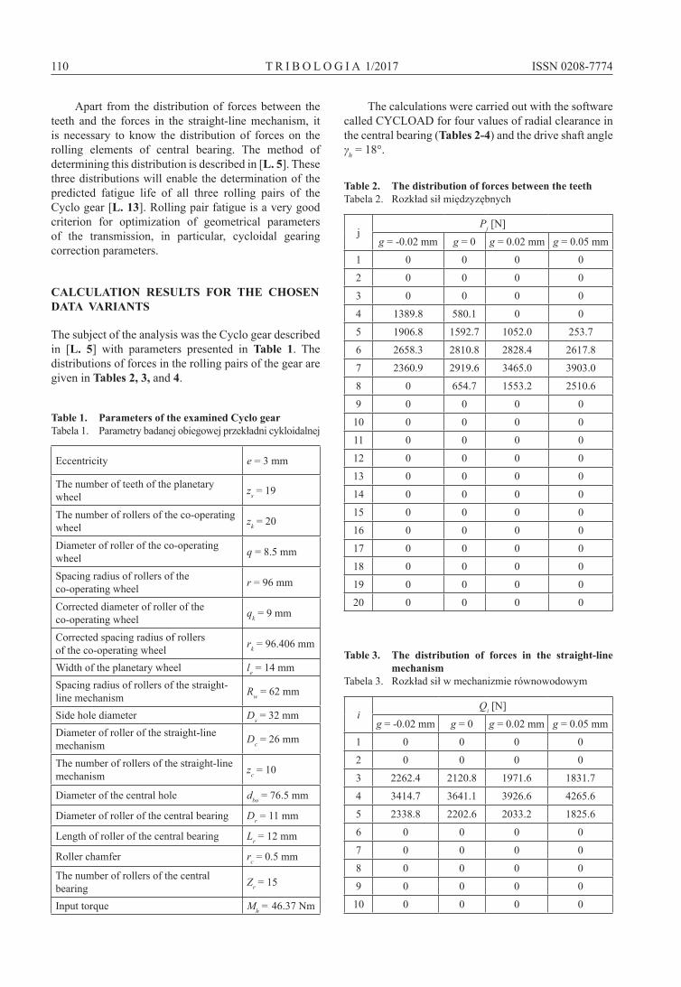
CALCULATION RESULTS FOR THE CHOSEN DATA VARIANTS
The subject of the analysis was the Cyclo gear described in [L. 5] with parameters presented in Table 1. The distributions of forces in the rolling pairs of the gear are given in Tables 2, 3, and 4.
Table 1. Parameters of the examined Cyclo gearTabela 1. Parametry badanej obiegowej przekładni cykloidalnej
Eccentricity e = 3 mm
The number of teeth of the planetary wheel zs = 19
The number of rollers of the co-operating wheel zk = 20
Diameter of roller of the co-operating wheel q = 8.5 mm
Spacing radius of rollers of the co-operating wheel r = 96 mm
Corrected diameter of roller of the co-operating wheel qk = 9 mm
Corrected spacing radius of rollers of the co-operating wheel rk = 96.406 mm
Width of the planetary wheel le = 14 mmSpacing radius of rollers of the straight-line mechanism Rw = 62 mm
Side hole diameter Ds = 32 mmDiameter of roller of the straight-line mechanism Dc = 26 mm
The number of rollers of the straight-line mechanism zc = 10
Diameter of the central hole dbo = 76.5 mm
Diameter of roller of the central bearing Dr = 11 mm
Length of roller of the central bearing Lr = 12 mm
Roller chamfer rc = 0.5 mm
The number of rollers of the central bearing Zr = 15
Input torque Mh = 46.37 Nm
The calculations were carried out with the software called CyCLOAD for four values of radial clearance in the central bearing (Tables 2-4) and the drive shaft angle γh = 18°.
Table 2. The distribution of forces between the teethTabela 2. Rozkład sił międzyzębnych
jPj [N]
g = -0.02 mm g = 0 g = 0.02 mm g = 0.05 mm
1 0 0 0 0
2 0 0 0 0
3 0 0 0 0
4 1389.8 580.1 0 0
5 1906.8 1592.7 1052.0 253.7
6 2658.3 2810.8 2828.4 2617.8
7 2360.9 2919.6 3465.0 3903.0
8 0 654.7 1553.2 2510.6
9 0 0 0 0
10 0 0 0 0
11 0 0 0 0
12 0 0 0 0
13 0 0 0 0
14 0 0 0 0
15 0 0 0 0
16 0 0 0 0
17 0 0 0 0
18 0 0 0 0
19 0 0 0 0
20 0 0 0 0
Table 3. The distribution of forces in the straight-line mechanism
Tabela 3. Rozkład sił w mechanizmie równowodowym
iQi [N]
g = -0.02 mm g = 0 g = 0.02 mm g = 0.05 mm
1 0 0 0 0
2 0 0 0 0
3 2262.4 2120.8 1971.6 1831.7
4 3414.7 3641.1 3926.6 4265.6
5 2338.8 2202.6 2033.2 1825.6
6 0 0 0 0
7 0 0 0 0
8 0 0 0 0
9 0 0 0 0
10 0 0 0 0
111ISSN 0208-7774 T R I B O L O G I A 1/2017
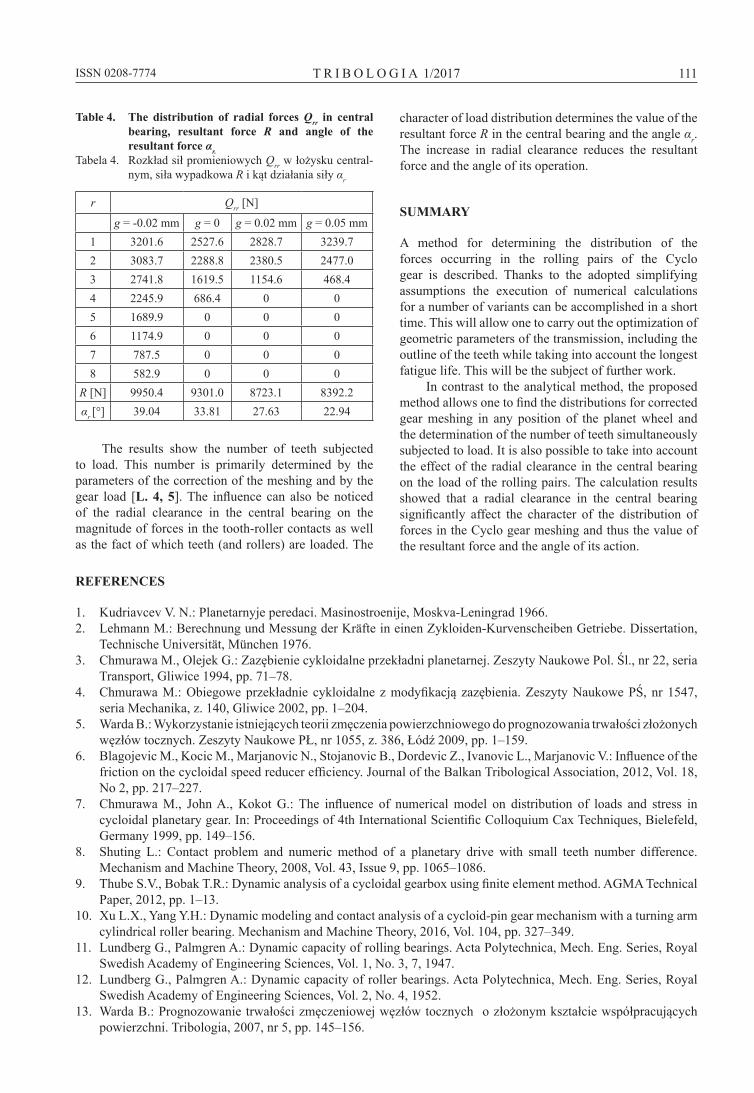
Table 4. The distribution of radial forces Qrr in central bearing, resultant force R and angle of the resultant force αr.
Tabela 4. Rozkład sił promieniowych Qrr w łożysku central-nym, siła wypadkowa R i kąt działania siły αr
r Qrr [N]
g = -0.02 mm g = 0 g = 0.02 mm g = 0.05 mm1 3201.6 2527.6 2828.7 3239.72 3083.7 2288.8 2380.5 2477.03 2741.8 1619.5 1154.6 468.44 2245.9 686.4 0 05 1689.9 0 0 06 1174.9 0 0 07 787.5 0 0 08 582.9 0 0 0
R [N] 9950.4 9301.0 8723.1 8392.2αr [°] 39.04 33.81 27.63 22.94
The results show the number of teeth subjected to load. This number is primarily determined by the parameters of the correction of the meshing and by the gear load [L. 4, 5]. The influence can also be noticed of the radial clearance in the central bearing on the magnitude of forces in the tooth-roller contacts as well as the fact of which teeth (and rollers) are loaded. The
character of load distribution determines the value of the resultant force R in the central bearing and the angle αr. The increase in radial clearance reduces the resultant force and the angle of its operation.
SUMMARY
A method for determining the distribution of the forces occurring in the rolling pairs of the Cyclo gear is described. Thanks to the adopted simplifying assumptions the execution of numerical calculations for a number of variants can be accomplished in a short time. This will allow one to carry out the optimization of geometric parameters of the transmission, including the outline of the teeth while taking into account the longest fatigue life. This will be the subject of further work.
In contrast to the analytical method, the proposed method allows one to find the distributions for corrected gear meshing in any position of the planet wheel and the determination of the number of teeth simultaneously subjected to load. It is also possible to take into account the effect of the radial clearance in the central bearing on the load of the rolling pairs. The calculation results showed that a radial clearance in the central bearing significantly affect the character of the distribution of forces in the Cyclo gear meshing and thus the value of the resultant force and the angle of its action.
REFERENCES
1. Kudriavcev V. N.: Planetarnyje peredaci. Masinostroenije, Moskva-Leningrad 1966.2. Lehmann M.: Berechnung und Messung der Kräfte in einen Zykloiden-Kurvenscheiben Getriebe. Dissertation,
Technische Universität, München 1976.3. Chmurawa M., Olejek G.: Zazębienie cykloidalne przekładni planetarnej. Zeszyty Naukowe Pol. Śl., nr 22, seria
Transport, Gliwice 1994, pp. 71–78.4. Chmurawa M.: Obiegowe przekładnie cykloidalne z modyfikacją zazębienia. Zeszyty Naukowe PŚ, nr 1547,
seria Mechanika, z. 140, Gliwice 2002, pp. 1–204.5. Warda B.: Wykorzystanie istniejących teorii zmęczenia powierzchniowego do prognozowania trwałości złożonych
węzłów tocznych. Zeszyty Naukowe Pł, nr 1055, z. 386, łódź 2009, pp. 1–159.6. Blagojevic M., Kocic M., Marjanovic N., Stojanovic B., Dordevic Z., Ivanovic L., Marjanovic V.: Influence of the
friction on the cycloidal speed reducer efficiency. Journal of the Balkan Tribological Association, 2012, Vol. 18, No 2, pp. 217–227.
7. Chmurawa M., John A., Kokot G.: The influence of numerical model on distribution of loads and stress in cycloidal planetary gear. In: Proceedings of 4th International Scientific Colloquium Cax Techniques, Bielefeld, Germany 1999, pp. 149–156.
8. Shuting L.: Contact problem and numeric method of a planetary drive with small teeth number difference. Mechanism and Machine Theory, 2008, Vol. 43, Issue 9, pp. 1065–1086.
9. Thube S.V., Bobak T.R.: Dynamic analysis of a cycloidal gearbox using finite element method. AGMA Technical Paper, 2012, pp. 1–13.
10. Xu L.X., yang y.H.: Dynamic modeling and contact analysis of a cycloid-pin gear mechanism with a turning arm cylindrical roller bearing. Mechanism and Machine Theory, 2016, Vol. 104, pp. 327–349.
11. Lundberg G., Palmgren A.: Dynamic capacity of rolling bearings. Acta Polytechnica, Mech. Eng. Series, Royal Swedish Academy of Engineering Sciences, Vol. 1, No. 3, 7, 1947.
12. Lundberg G., Palmgren A.: Dynamic capacity of roller bearings. Acta Polytechnica, Mech. Eng. Series, Royal Swedish Academy of Engineering Sciences, Vol. 2, No. 4, 1952.
13. Warda B.: Prognozowanie trwałości zmęczeniowej węzłów tocznych o złożonym kształcie współpracujących powierzchni. Tribologia, 2007, nr 5, pp. 145–156.