3-Phase Transformer magnetization current · PDF file3-Phase Transformer magnetization current...
11
Materiały dydaktyczne dystrybuowane bezpłatnie. Projekt współfinansowany ze środków Unii Europejskiej w ramach Europejskiego Funduszu Społecznego 1 WARSAW UNIVERSITY OF TECHNOLOGY INSTITUTE OF ELECTRICAL MACHINES ELECTRICAL MACHINES IN THE POWER ENGINEERING AND AUTOMATIC 3-Phase Transformer magnetization current test Introduction Primary voltage E 1 is balanced by emf E i forced by flux exciting current I f (which waveform is different from sinusoidal due to iron core non linear characteristic) and drop of voltage over winding impedance Z 1 = sqrt(X 1 2 + R 1 2 ) – Fig.1. Fig.1. Equivalent open circuit of the no-load transformer. Fig.2. Primary voltage U 1 , emf E 1 , exciting current i 0 i and main flux fi waveforms. Core exciting current I 0 flows in the primary transformer winding independently of the load. It has two components: I f , the magnetizing component which flows 90° lagging behind induced voltage E 1 ; and I ow , the core-loss current which is in phase with E 1 . Ordinarily this current is small and produces negligible voltage drop in the winding. Core-loss current has two components: eddy current and hysteresis. Eddy-current loss is caused by current circulating in the core laminations. Hysteresis loss is the power required to magnetize the core
Transcript of 3-Phase Transformer magnetization current · PDF file3-Phase Transformer magnetization current...

Materiały dydaktyczne dystrybuowane bezpłatnie.
Projekt współfinansowany ze środków Unii Europejskiej w ramach Europejskiego Funduszu Społecznego
1
WARSAW UNIVERSITY OF TECHNOLOGY
INSTITUTE OF ELECTRICAL MACHINES
ELECTRICAL MACHINES IN THE POWER ENGINEERING AND AUTOMATIC
3-Phase Transformer magnetization current test
Introduction
Primary voltage E1 is balanced by emf Ei forced by flux exciting current If (which
waveform is different from sinusoidal due to iron core non linear characteristic) and drop of
voltage over winding impedance Z1 = sqrt(X12 + R1
2) – Fig.1.
Fig.1. Equivalent open circuit of the no-load transformer.
Fig.2. Primary voltage U1, emf E1, exciting current i0 i and main flux fi waveforms.
Core exciting current I0 flows in the primary transformer winding independently of the
load. It has two components: If, the magnetizing component which flows 90° lagging behind
induced voltage E1; and Iow, the core-loss current which is in phase with E1. Ordinarily this
current is small and produces negligible voltage drop in the winding. Core-loss current has
two components: eddy current and hysteresis. Eddy-current loss is caused by current
circulating in the core laminations. Hysteresis loss is the power required to magnetize the core

Materiały dydaktyczne dystrybuowane bezpłatnie.
Projekt współfinansowany ze środków Unii Europejskiej w ramach Europejskiego Funduszu Społecznego
2
first in one direction and then in the other on alternating half-cycles. Hysteresis loss and
magnetization are intimately connected, as can be seen from Fig.3.
Fig.3. Transformer voltage, flux, and exciting current.
Although the applied voltage to a transformer is sinusoidal, the magnetization current
related to the flux through the magnetization curve is non-sinusoidal, as shown in Fig.3. The
non-sinusoidal current is symmetrical around its peak. Such a waveform is mainly composed
of odd harmonics. In particular, the 3rd harmonic, as well as the 5th and the 7th harmonics
have a significant contribution.
3-Phase Transformer connections influence on phase current and voltage higher
harmonics
Wye connection without zero line (Fig.4) cannot provide higher third order
harmonics (3-rd and 9-th order – triplen harmonics) of current to flow.
Fig.4. Wye connection without zero line.

Materiały dydaktyczne dystrybuowane bezpłatnie.
Projekt współfinansowany ze środków Unii Europejskiej w ramach Europejskiego Funduszu Społecznego
3
The flux waveform has to contain higher third order harmonics and in consequence phase
voltage Uph1 also contains higher third order harmonics as it is explained in Fig.5.
Fig.5. Phase voltage in case of absence of third order harmonics in the magnetizing current.
Notice that Wye connection without zero line can provide other higher odd current harmonics
(for example 5-th and 7-th order harmonics). However higher odd harmonics do not exist in
the line voltages U1. Distorted phase voltage has higher peak value that can be dangerous for
load.
Wye connection with zero line. Additional zero line allows third order current
harmonics to flow (Fig.6). The neutral wire carries three times the third order harmonic
current of one transformer as these currents are co-phasal.
Fig.6. Wye connection with zero line.
In consequence the flux waveforms don’t contain third order harmonics and in consequence
phase voltage Uph1 also doesn’t contain higher order harmonics (Fig.7). Higher current
harmonics exist in the phase current.
Fig.7. Phase voltage in case of existence of third order harmonics in the magnetizing current.

Materiały dydaktyczne dystrybuowane bezpłatnie.
Projekt współfinansowany ze środków Unii Europejskiej w ramach Europejskiego Funduszu Społecznego
4
Wye – Delta connection (Fig.8). In this case the higher current harmonics (especillly
higher third order harmonics) can flow in delta circuit, the flux waveforms don’t contain
higher odd harmonics. The third order harmonic currents inside the closed delta winding
correct the flux wave to be nearly sinusoidal and in consequence phase voltage Uph1 also
doesn’t contain higher order harmonics (Fig.7). However higher current harmonics (other than
higher third order harmonics) can exist in the phase current.
Fig.8. Wye-Delta connection.
Test circuit connections
Tested Transformer is 5-column symmetrical 3-pase one with Wye primary side
connection.
Fig.9. Connection diagram.
Voltage and current measurement block terminals should be connected to the data acquisition
device USB-6251 in the following order:

Materiały dydaktyczne dystrybuowane bezpłatnie.
Projekt współfinansowany ze środków Unii Europejskiej w ramach Europejskiego Funduszu Społecznego
5
Voltage measurement
block terminal
Data acquisition device
USB-6251
Current measurement
block terminal
Data acquisition device
USB-6251
U1 AI 0 I1 AI 6
U2 AI 1 I2 AI 7
U3 AI 2 I3 AI 8
U4 AI 3 I4 AI 9
U5 AI 4 I5 AI 10
U6 AI 5 I6 AI 11
Ratings of the transformer to be tested:
Ratings
Voltage Uph1N 220V
Voltage Uph2N 220V
Apparent Power SN 3x3 kVA
Connection diagram is presented in Fig.9.Supply voltage unit consists of Induction
Voltage Regulator and additional Wye-Wye connected transformer securing possibility to
realize (using W1 switch) zero line connection. Tested transformer secodary side can be Delta
connected using W2 switch. Transformer voltages and currents are measured using voltage-
voltage and current-voltage converters that offer galvanic signal separation.
Fig.10. VI interface window.
Materiały dydaktyczne dystrybuowane bezpłatnie.
Projekt współfinansowany ze środków Unii Europejskiej w ramach Europejskiego Funduszu Społecznego
6
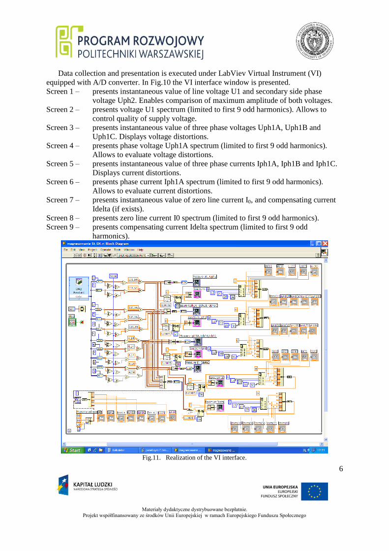
Data collection and presentation is executed under LabViev Virtual Instrument (VI)
equipped with A/D converter. In Fig.10 the VI interface window is presented.
Screen 1 – presents instantaneous value of line voltage U1 and secondary side phase
voltage Uph2. Enables comparison of maximum amplitude of both voltages.
Screen 2 – presents voltage U1 spectrum (limited to first 9 odd harmonics). Allows to
control quality of supply voltage.
Screen 3 – presents instantaneous value of three phase voltages Uph1A, Uph1B and
Uph1C. Displays voltage distortions.
Screen 4 – presents phase voltage Uph1A spectrum (limited to first 9 odd harmonics).
Allows to evaluate voltage distortions.
Screen 5 – presents instantaneous value of three phase currents Iph1A, Iph1B and Iph1C.
Displays current distortions.
Screen 6 – presents phase current Iph1A spectrum (limited to first 9 odd harmonics).
Allows to evaluate current distortions.
Screen 7 – presents instantaneous value of zero line current I0, and compensating current
Idelta (if exists).
Screen 8 – presents zero line current I0 spectrum (limited to first 9 odd harmonics).
Screen 9 – presents compensating current Idelta spectrum (limited to first 9 odd
harmonics).
Fig.11. Realization of the VI interface.

Materiały dydaktyczne dystrybuowane bezpłatnie.
Projekt współfinansowany ze środków Unii Europejskiej w ramach Europejskiego Funduszu Społecznego
7
In the area above screens RMS values of appropriate qantities are presented. In Fig.11
realization of the VI interface window is presented.
Starting of VI instrument and test circuit arrangement.
Transformer test circuit is already connected. However some additional connections
should be done in appropriate (described below) sequence:
1- Switch “on” the computer (wait for operation system up-loading).
2- Switch “on” the data acquisition device USB-6251. On the computer screen the
tool program selection window appears (Fig.12).
Fig.12. Tool program selection window.
3- Activate the LabViev 8.21 icon.
4- Chose the file “magnesowanie 5k EN” that appear in the starting window „Open”
of the LabView program. The VI window as presented in Fig.10 should appear.
5- Switch „on” the voltage-voltage and current-voltage converters box.
6- Arrange proper connection of tested transformer supply voltage using the
Induction Voltage Regulator. Notice that initial voltage setting should be should be
set to minimum.
7- Switch „on” the Induction Voltage Regulator.
8- Set the appropriate supply voltage.
9- Set appropriate transformer connection (Wye without zero line, Wye with zero line
or Wye-Delta).
10- Start measurements activating VI instrument „START” button positioned in the
tools rib (Fig.13).

Materiały dydaktyczne dystrybuowane bezpłatnie.
Projekt współfinansowany ze środków Unii Europejskiej w ramach Europejskiego Funduszu Społecznego
8
Fig.13. VI instrument „START” button.
After finishing measurements firstly:
1- Switch “off” the Induction Voltage Regulator after setting output voltage to
minimum.
2- Disconnect the Induction Voltage Regulator.
3- Switch “off” the voltage-voltage and current-voltage converters box.
4- Switch “off” the data acquisition device USB-6251.
5- Close the computer.
Measurement data collection and elaboration
Measurement should be performed for 3 values of supply voltage for each transformer
connection (Wye without zero line, Wye with zero line or Wye-Delta). Results of harmonic
analysis of phase voltage Uph1, phase current Iph1 and if necessary zero line voltage I0 or
compensation current Idelta from VI interface window should be placed in appropriate Table.
Table1
Wye connection without zero line
Uph1=200V Harmonic order
1 3 5 7 9
U1
Uph1
Iph1
I0
Idelta
Table2
Wye connection without zero line
Uph1=300V Harmonic order
1 3 5 7 9
U1
Uph1
Iph1
I0
Idelta

Materiały dydaktyczne dystrybuowane bezpłatnie.
Projekt współfinansowany ze środków Unii Europejskiej w ramach Europejskiego Funduszu Społecznego
9
Table3
Wye connection without zero line
Uph1=350V Harmonic order
1 3 5 7 9
U1
Uph1
Iph1
I0
Idelta
Table4
Wye connection with zero line
Uph1=200V Harmonic order
1 3 5 7 9
U1
Uph1
Iph1
I0
Idelta
Table5
Wye connection with zero line
Uph1=300V Harmonic order
1 3 5 7 9
U1
Uph1
Iph1
I0
Idelta
Table6
Wye connection with zero line
Uph1=350V Harmonic order
1 3 5 7 9
U1
Uph1
Iph1
I0
Idelta

Materiały dydaktyczne dystrybuowane bezpłatnie.
Projekt współfinansowany ze środków Unii Europejskiej w ramach Europejskiego Funduszu Społecznego
10
Table7
Wye – Delta connection
Uph1=200V Harmonic order
1 3 5 7 9
U1
Uph1
Iph1
I0
Idelta
Table8
Wye – Delta connection
Uph1=300V Harmonic order
1 3 5 7 9
U1
Uph1
Iph1
I0
Idelta
Table9
Wye – Delta connection
Uph1=350V Harmonic order
1 3 5 7 9
U1
Uph1
Iph1
I0
Idelta
On the base of measurement data on the separate drawings phase voltage Uph1 or phase
current Iph1 harmonic content should be presented in two ways. First revealing the
development of higher order harmonics with supply voltage change (parameter is the winding
connection arrangement). Second revealing the content of higher harmonics that depends on
winding connection arrangement (parameter is the supply voltage).
Drawings should be commented:
1- What winding connection arrangement guarantees best quality of distributed
electrical energy?
2- What is the advantage (if there is any) of Wye connection with zero line against
Wye-Delta connection (or opposite)?
Materiały dydaktyczne dystrybuowane bezpłatnie.
Projekt współfinansowany ze środków Unii Europejskiej w ramach Europejskiego Funduszu Społecznego
11
Literature:
Adam Biernat, Power Transformers – part of the lecture: Electric Machines in the Power
Engineering and Automatics.
Instruction elaborated by Adam Biernat