![INDEX [] · 2010. 6. 11. · # SM5082 Santana, Suzuki Escudo, Santana, Sidekick, Vitara, X90 - F 89-99 Mounting Kit, Spring Seat, RN Series # SM5109 Mitsubishi, Proton Colt, Mirage,](https://static.fdocuments.pl/doc/165x107/60c49f17f411dc1b6c4bad9e/index-2010-6-11-sm5082-santana-suzuki-escudo-santana-sidekick-vitara.jpg)
2005 - SUZUKI GRAND VITARA - Carpratik · Suzuki Grand Vitara 5 drz. 96-111 Kowiesy, Chojnata 23 A...
7
Cat. No. 2000Kg 85Kg SUZUKI GRAND VITARA 5d., com. 2005 - V/026 e20*94/20*0603*00 10,50kN
Transcript of 2005 - SUZUKI GRAND VITARA - Carpratik · Suzuki Grand Vitara 5 drz. 96-111 Kowiesy, Chojnata 23 A...
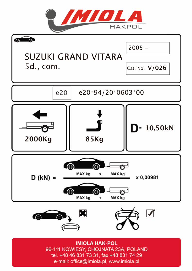
Cat. No.
2000Kg 85Kg
SUZUKI GRAND VITARA5d., com.
2005 -
V/026
e20*94/20*0603*00
10,50kN
�
�
�
�
�
�
�
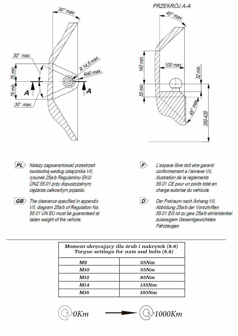
0Km 1000Km
Moment skręcający dla śrub i nakrętek (8.8) Torgue settings for nuts and bolts (8.8)
M8
M10
M12
M14
M16
25Nm
55Nm
85Nm
135Nm
195Nm
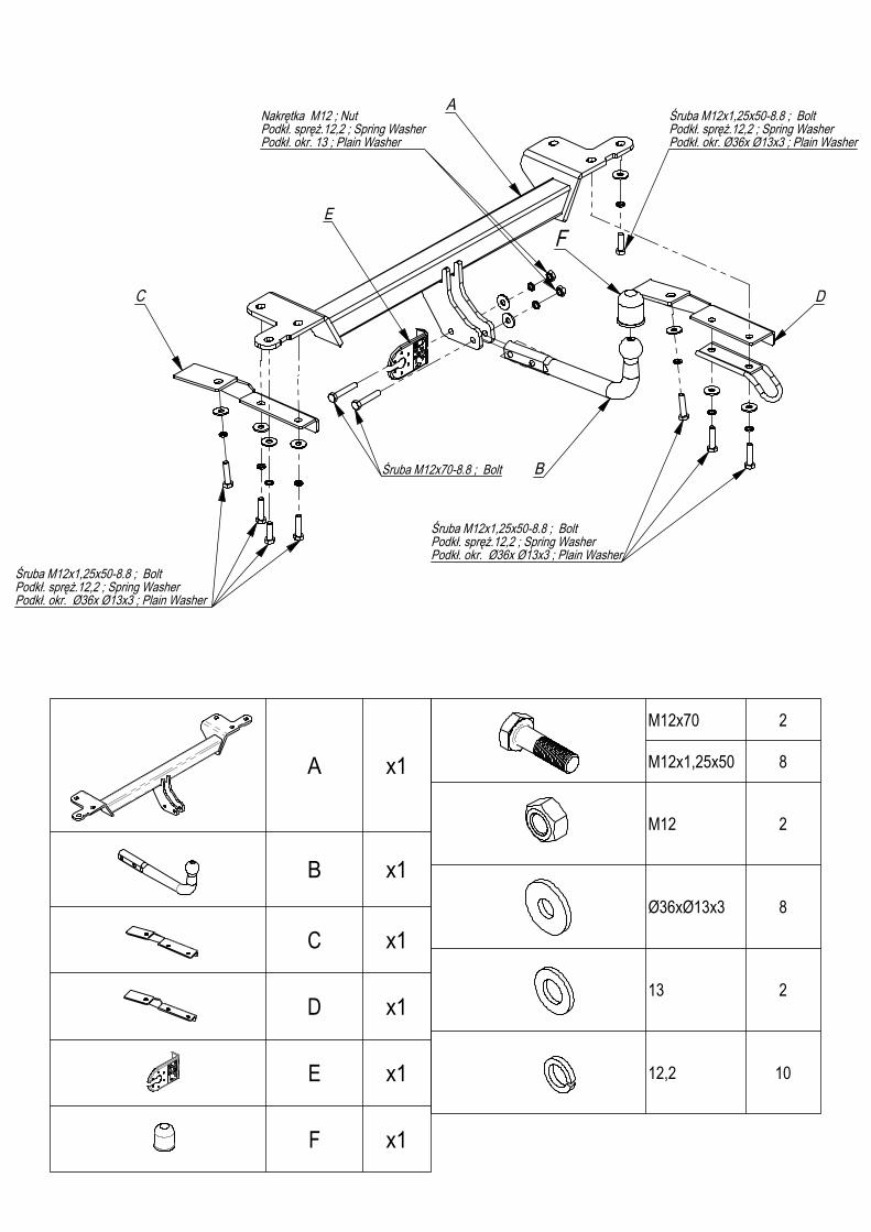
Śruba M12x1,25x50-8.8 ; BoltPodkł. spręż.12,2 ; Spring WasherPodkł. okr. Ø36x Ø13x3 ; Plain Washer
A
B
C D
Nakrętka M12 ; NutPodkł. spręż.12,2 ; Spring WasherPodkł. okr. 13 ; Plain Washer
Śruba M12x1,25x50-8.8 ; BoltPodkł. spręż.12,2 ; Spring WasherPodkł. okr. Ø36x Ø13x3 ; Plain Washer
Śruba M12x1,25x50-8.8 ; BoltPodkł. spręż.12,2 ; Spring WasherPodkł. okr. Ø36x Ø13x3 ; Plain Washer
FE
Śruba M12x70-8.8 ; Bolt
A x1
B x1
C x1
D x1
E x1
F x1
M12x70 2
M12x1,25x50 8
M12 2
Ø36xØ13x3 8
13 2
12,2 10
M16 2M12 2M10 2M8 2M6 2Ø36xØ13x3 2Ø30xØ10,5x3 2Ø23xØ8,5x2 2Ø18xØ6,5x1,5 2
12,2 210,2 28,2 26,1 2
13 210,5 28,5 26,5 2
M12 2M10 2
Śrub
a M12
x1,25
x50-
8.8 ;
Bolt
Podk
ł. spr
ęż.12
,2 ; S
pring
Was
her
Podk
ł. okr.
Ø36
x Ø13
x3 ; P
lain W
ashe
r
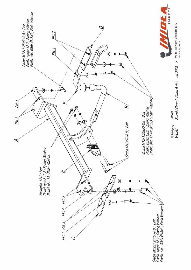
A
B
C
D
Pkt. 4
Pkt. 4
Nakrę
tka M
12 ; N
utPo
dkł. s
pręż
.12,2
; Spr
ing W
ashe
rPo
dkł. o
kr. 13
; Plai
n Was
her
Pkt. 1
Pkt. 1
Pkt. 2
Pkt. 2
Pkt. 3
Pkt. 3
Śrub
a M12
x1,25
x50-
8.8 ;
Bolt
Podk
ł. spr
ęż.12
,2 ; S
pring
Was
her
Podk
ł. okr.
Ø36
x Ø13
x3 ; P
lain W
ashe
rŚr
uba M
12x1
,25x5
0-8.8
; Bo
ltPo
dkł. s
pręż
.12,2
; Spr
ing W
ashe
rPo
dkł. o
kr. Ø
36x Ø
13x3
; Plai
n Was
her
FE
Śrub
a M12
x70-
8.8 ;
Bolt
Nr ka
talog
owy
V/02
6Ma
rkaod
2005
- >
Suzu
ki Gr
and
Vita
ra 5
drz
.96
-111
Kow
iesy
, Cho
jnat
a 23
Ate
l. +4
8 46
831
73
31
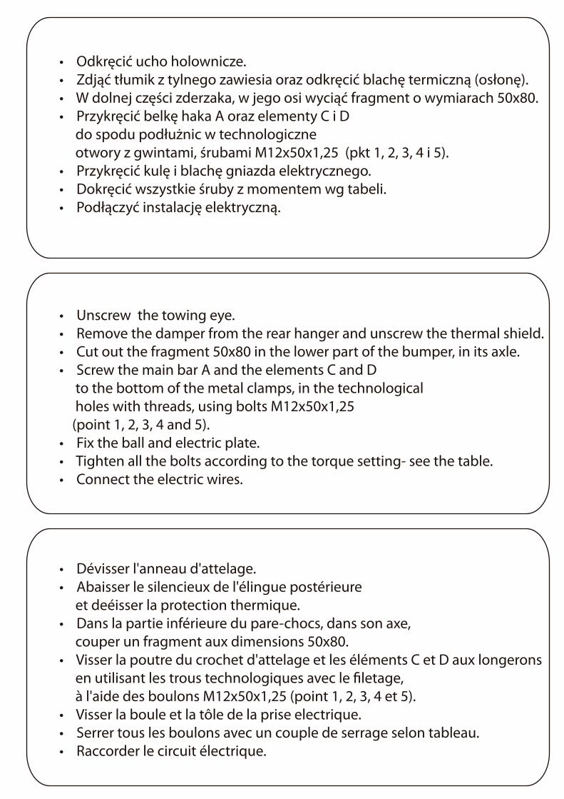
• Odkręcić ucho holownicze.
• Zdjąć tłumik z tylnego zawiesia oraz odkręcić blachę termiczną (osłonę).
• W dolnej części zderzaka, w jego osi wyciąć fragment o wymiarach 50x80.
• Przykręcić belkę haka A oraz elementy C i D
do spodu podłużnic w technologiczne
otwory z gwintami, śrubami M12x50x1,25 (pkt 1, 2, 3, 4 i 5).
• Przykręcić kulę i blachę gniazda elektrycznego.
• Dokręcić wszystkie śruby z momentem wg tabeli.
• Podłączyć instalację elektryczną.
• Unscrew the towing eye.
• Remove the damper from the rear hanger and unscrew the thermal shield.
• Cut out the fragment 50x80 in the lower part of the bumper, in its axle.
• Screw the main bar A and the elements C and D
to the bottom of the metal clamps, in the technological
holes with threads, using bolts M12x50x1,25
(point 1, 2, 3, 4 and 5).
• Fix the ball and electric plate.
• Tighten all the bolts according to the torque setting- see the table.
• Connect the electric wires.
• Dévisser l'anneau d'attelage.
• Abaisser le silencieux de l'élingue postérieure
et deéisser la protection thermique.
• Dans la partie inférieure du pare-chocs, dans son axe,
couper un fragment aux dimensions 50x80.
• Visser la poutre du crochet d'attelage et les éléments C et D aux longerons
en utilisant les trous technologiques avec le �letage,
à l'aide des boulons M12x50x1,25 (point 1, 2, 3, 4 et 5).
• Visser la boule et la tôle de la prise electrique.
• Serrer tous les boulons avec un couple de serrage selon tableau.
• Raccorder le circuit électrique.
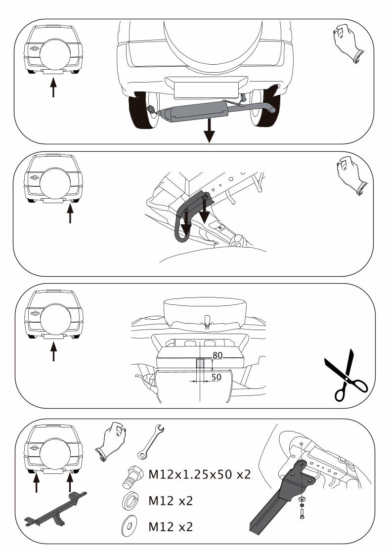
M12x1.25x50 x2
M12 x2
M12 x2
50
80
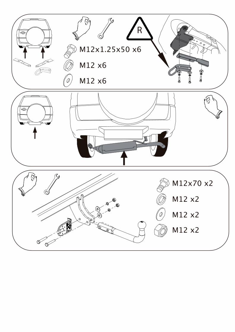
M12x70 x2
M12 x2
M12 x2
M12 x2
R
M12x1.25x50 x6
M12 x6
M12 x6


![STANDOX SUZUKI 2010 [Kompatibilitätsmodus] · grand vitara grand vitara ignis liana liana swift wagon wagon aero esteem grand vitara liana swift wagon r xl7 alto jimny samurai vitara](https://static.fdocuments.pl/doc/165x107/5fef4dabfc992d045979d5e7/standox-suzuki-2010-kompatibilittsmodus-grand-vitara-grand-vitara-ignis-liana.jpg)