%PDF-1.3 Èß²&ÞÐ ºÉÞ ...IAC+... · %PDF-1.3 %Çì ¢ 5 0 obj stream x í[m

207
USING A CODE LEVELER TO MEASURE THE LENGTH OF SHORT SEGMENTS
Janusz Kuchmister, Kazimierz Ćmielewski, Bartłomiej Ćmielewski, Krzysztof Mąkolski
Institute of Geodesy and Geoinformatics, Wroclaw University of Environmental and Life Sciences
[email protected], [email protected], [email protected], [email protected]
SUMMARY During measurements or setting out geometrical values of engineering objects various inconveniences and obstacles can appear while using traditional geodesic measurement methods. Such situations can happen during the process of measurement or setting out as a result of the length of the project, based on building – assembly which is used to precisely set subassemblies of machines or devices. The authors use, to measure a segment of precise length, an equipped code leveler which allows them to skip obstacles present in the measured space which is necessary to perform geodetic monitoring. The poster shows results of the performed fragmental and complex researches – measurements of the applied device and setting out and measuring horizontal lengths. Chosen natural influences: environmental, legislative actions, measurement failures and others, which can influence the results of observations by means of DNA 03 leveler, were defined as a result of fragmentaristic researches. Running complex research works based on the long term allowed one to define measurement precision of various segments length by means of battens of various division (fiberglass batten: metrical and code division, precise code batten ). 1. INTRODUCTION
During measurements or setting out geometrical values of engineering objects various inconveniences and obstacles can appear while using traditional geodesic measurement methods. Such situations can happen during the process of measurement or setting out as a result of the length of the project, based on building – assembly which is used to precisely set subassembly of machines or devices. Limited availability of elements subjected to measurements which results from built coverings (i.e. Assembly lines of subassembly for cars, etc.) and their location in monitored space (i.e. Presses, foil producing machines, turbo generators(Gillardizzi and co., 1999, Sprint, Hudson, 1996)), as well as shapes of used elements (i.e. slides , rollers, axis elements (Fuss, Teskey, 1993)), determine the process of measurement by the means of known instruments.

208
Very often measurement processes have to take place in periods of time adjusted to assembly or modernization of the elements of an engineering object. The problem of a periodic reference on measurements appears i.e. length with retaining receptions and permanence of precision. The idea of a method proposed by W. Janusz (Janusz W., 1978) of measurements of short distances with use of hatched battens for precise leveling was an inspiration for the authors to elaborate an application for measurements of short distances with use of a precise code leveler. 2. EXPERIMENTAL WORKS ON LENGTH BASE
Particular elements of proposed measurement set in a defined measurement sequence were used during fragments and complex experiments. A standard leveler set, in the proposed measurement method, was enriched, in reference to a leveler, by an optical cap which brakes at the straight angle intentional axis. Additionally a laser diode was attached to the cap. The tripod was equipped in a jack with a level and rope plumb-line to vertically orientate the axis of leveler rotation. A standard leveling batten was set in a horizontal position by the means of a spirit level on a leveling head with handles. The front of a batten is equipped at the ends with direction adapters with rope plumb-lines (laser ones) which allow directing the axis of a batten along the measured segment. A sliding centering plate which defines the symmetry axis of the batten is mounted on the surface of a batten. Cooperation and connection of the separate elements is presented in figure 1.
Fig. 1. A complete measurement set.
During fragmental researches which were run on a 2,50 m fragment of a length base, sequence of placement actions were established and errors of those actions and measurement errors which have vital influence on monitoring results which are made with a measurement set. Complex researches were run on a 8,00 m fragment of a length base which was composed of four 1,00 m fragments and two 2,00 m ones. The researches allowed us to define measurement precisions of segments of various length when battens of a different division were used (fiberglass batten: metrical and code

209
division, precise code batten). Additionally the segment of 8,00 m, which was situated parallel to the base and moved for 0,50m , was also measured. In figure 1,2 and 3 initial settings of a batten along the measured segment are presented, precise setting of the axis of the batten along the measured segment by the means of direction adapter which is equipped with a plumb-line, and setting the axis of a leveler over the axis of a batten with a centering plate and rope plumbing-line.
Fig. 2. View of a leveling batten initially set along the measured segment and leveled
by a plumb-line.

210
Fig. 3. View of precise setting of the batten axis by directing cap and a plumb-line along
the measured segment.
Fig. 4. View of a setting of a vertical leveler axis over the axis of a batten
with a centering plate and rope plumbing-line.
211
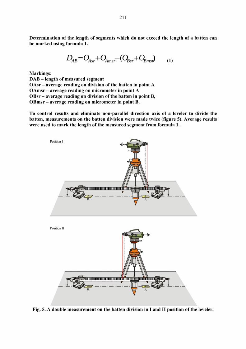
Determination of the length of segments which do not exceed the length of a batten can be marked using formula 1.
)( BmsrBsrAmsrAsrAB OOOOD +−+= (1) Markings: DAB – length of measured segment OAsr – average reading on division of the batten in point A OAmsr – average reading on micrometer in point A OBsr – average reading on division of the batten in point B, OBmsr – average reading on micrometer in point B. To control results and eliminate non-parallel direction axis of a leveler to divide the batten, measurements on the batten division were made twice (figure 5). Average results were used to mark the length of the measured segment from formula 1.
Fig. 5. A double measurement on the batten division in I and II position of the leveler.

212
In figure 6 we can see an example of a situation using measured segments on a ceiling and the length base running under the tripod. In figure 7 we can see an example of a situation using measured segments on a wall and the length base running under the tripod.
Fig. 6. A view of the leveling batten fitted to the ceiling during measurement.
Fig. 7. A view of the leveling batten fitted to the wall during measurement.
213
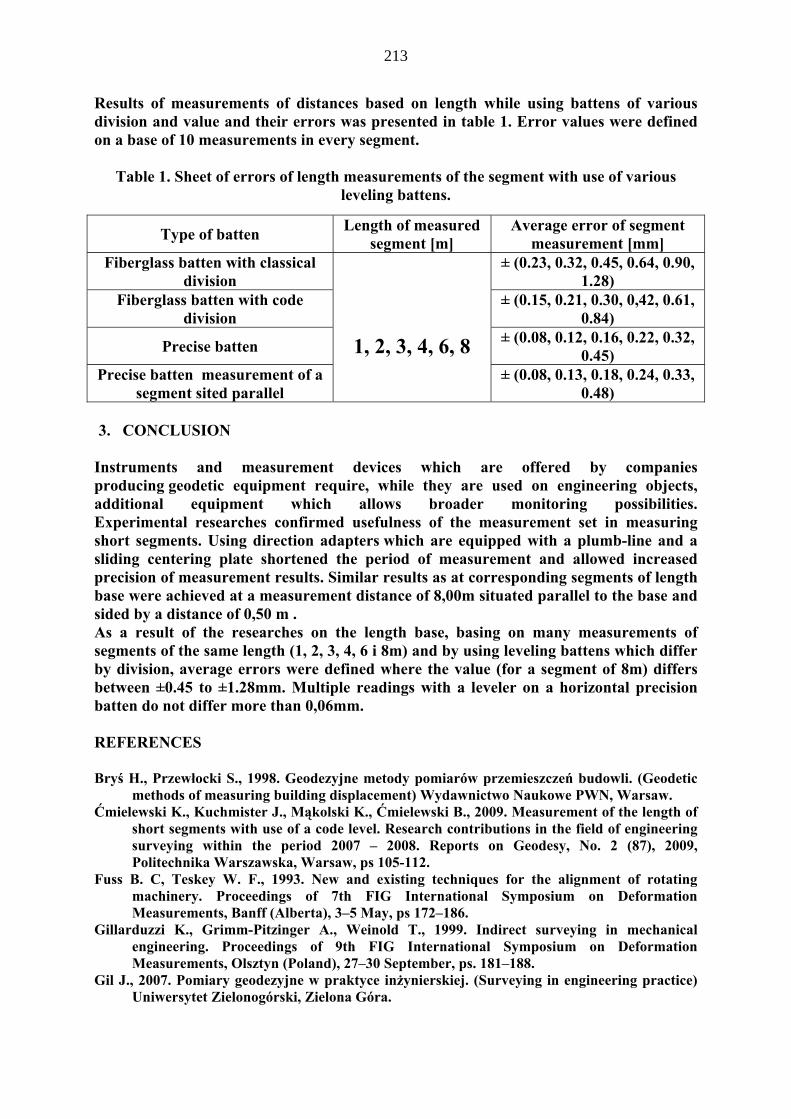
Results of measurements of distances based on length while using battens of various division and value and their errors was presented in table 1. Error values were defined on a base of 10 measurements in every segment.
Table 1. Sheet of errors of length measurements of the segment with use of various
leveling battens.
3. CONCLUSION
Instruments and measurement devices which are offered by companies producing geodetic equipment require, while they are used on engineering objects, additional equipment which allows broader monitoring possibilities. Experimental researches confirmed usefulness of the measurement set in measuring short segments. Using direction adapters which are equipped with a plumb-line and a sliding centering plate shortened the period of measurement and allowed increased precision of measurement results. Similar results as at corresponding segments of length base were achieved at a measurement distance of 8,00m situated parallel to the base and sided by a distance of 0,50 m . As a result of the researches on the length base, basing on many measurements of segments of the same length (1, 2, 3, 4, 6 i 8m) and by using leveling battens which differ by division, average errors were defined where the value (for a segment of 8m) differs between ±0.45 to ±1.28mm. Multiple readings with a leveler on a horizontal precision batten do not differ more than 0,06mm. REFERENCES Bryś H., Przewłocki S., 1998. Geodezyjne metody pomiarów przemieszczeń budowli. (Geodetic
methods of measuring building displacement) Wydawnictwo Naukowe PWN, Warsaw. Ćmielewski K., Kuchmister J., Mąkolski K., Ćmielewski B., 2009. Measurement of the length of
short segments with use of a code level. Research contributions in the field of engineering surveying within the period 2007 – 2008. Reports on Geodesy, No. 2 (87), 2009, Politechnika Warszawska, Warsaw, ps 105-112.
Fuss B. C, Teskey W. F., 1993. New and existing techniques for the alignment of rotating machinery. Proceedings of 7th FIG International Symposium on Deformation Measurements, Banff (Alberta), 3–5 May, ps 172–186.
Gillarduzzi K., Grimm-Pitzinger A., Weinold T., 1999. Indirect surveying in mechanical engineering. Proceedings of 9th FIG International Symposium on Deformation Measurements, Olsztyn (Poland), 27–30 September, ps. 181–188.
Gil J., 2007. Pomiary geodezyjne w praktyce inżynierskiej. (Surveying in engineering practice) Uniwersytet Zielonogórski, Zielona Góra.
Type of batten Length of measured segment [m]
Average error of segment measurement [mm]
Fiberglass batten with classical division
1, 2, 3, 4, 6, 8
± (0.23, 0.32, 0.45, 0.64, 0.90, 1.28)
Fiberglass batten with code division
± (0.15, 0.21, 0.30, 0,42, 0.61, 0.84)
Precise batten ± (0.08, 0.12, 0.16, 0.22, 0.32, 0.45)
Precise batten measurement of a segment sited parallel
± (0.08, 0.13, 0.18, 0.24, 0.33, 0.48)

214
Gocał J., 1993. Metody i instrumenty geodezyjne w precyzyjnych pomiarach maszyn i urządzeń mechanicznych. (Methods of surveying and instruments in precision measurement machines and mechanical equipment.) Wydawnictwo AGH, Kraków.
Janusz W., 1978. Methods of precision measurements of horizontal and vertical distances. FIG, Commission 6: Engineering Surveys, II International Symposium on deformation measurements by geodetic methods, Bonn.
Janusz W., Ostrowski R., Zykubek S., 1984. Metoda precyzyjnego pomiaru krótkich odległości. (The method of precise measurement of short distances.) Prace IGiK, T. XXIX, Z. 1/74/.
Sprent A., Hudson A. J., 1996. Paper mill alignment survey. Proceedings of 8th FIG International Symposium on Deformation Measurements, Hung Hom (Hong Kong), 25–28 June, ps 91–96.


![SHORT NOTES* - aph-ihpan.edu.pl · SHORT NOTES* GENERAL WORKS Aleksander Gieysztor, Władza – symbole i rytuały [Power, its symbols and rituals], ed. by Przemysław Mrozowski,](https://static.fdocuments.pl/doc/165x107/5c784c0009d3f2cd0e8c9073/short-notes-aph-ihpanedupl-short-notes-general-works-aleksander-gieysztor.jpg)


![KRÓTKIE FORMY MUZYCZNE [1'-10'] SHORT MUSICAL FORMS [1 ...](https://static.fdocuments.pl/doc/165x107/587612c91a28ab7b578b869e/krotkie-formy-muzyczne-1-10-short-musical-forms-1-.jpg)