
The computational-fluid-dynamics study of an unbaffled stirred vessel ... · Impellers were located...
10
RYSZARD WÓJTOWICZ * , ANDREY A. LIPIN ** THE COMPUTATIONAL-FLUID-DYNAMICS STUDY OF AN UNBAFFLED STIRRED VESSEL WITH ECCENTRICALLY POSITIONED IMPELLER SYMULACJE CFD MIESZALNIKA BEZ PRZEGRÓD Z NIECENTRYCZNIE SYTUOWANYM MIESZADŁEM Abstract The paper presents the results of CFD simulations of liquid flow in an unbaffled stirred vessel with an eccentrically positioned impeller. The influence of the impeller’s distance from the tank axis (eccentricity) on the generated flow circulation was analyzed. Based on numerical modelling, the flow pattern, vortex formation as well as turbulence parameters in selected stirred vessel zones were determined. Obtained results were presented as vector/contour maps, and iso-surfaces of Q-criterion for identification of vortex cores. Additionally, for each investigated stirred vessel power consumption was calculated. Keywords: mixing, stirred vessel, liquid flow, CFD simulations, impeller eccentricity Streszczenie W pracy przedstawiono wyniki symulacji CFD ruchu cieczy w mieszalniku mechanicznym bez przegród z niecentrycznie usytuowanym mieszadłem. Analizowano wpływ zmian odległości mieszadła od osi aparatu (niecentryczności) na generowaną w mieszalniku cyrkulację. Na podstawie modelowania numerycznego wyznaczono model przepływu cieczy, strefy tworzenia się wirów oraz parametry turbulencji w wybranych obszarach mieszalnika. Uzyskane wyniki przedstawiono w postaci wektorowych i konturowych map roz- kładu, do identyfikacji położenia rdzeni wirów wykorzystano powierzchnie stałych wartości Q-kryterium. Dodatkowo w każdym z badanych mieszalników wyznaczono zapotrzebowanie mocy. Słowa kluczowe: mieszanie, mieszalnik, przepływ cieczy, symulacje CFD, niecentryczność mieszadła DOI: 10.4467/2353737XCT.15.109.4057 * Ph.D. Eng. Ryszard Wójtowicz, Institute of Thermal and Process Engineering, Faculty of Mechanical Engineering, Cracow University of Technology. ** Ph.D. Eng. Andrey A. Lipin, Faculty of Chemical Engineering and Cybernetics, Ivanovo State University of Chemistry and Technology, Ivanovo, Russia.
Transcript of The computational-fluid-dynamics study of an unbaffled stirred vessel ... · Impellers were located...

RYSZARD WÓJTOWICZ*, ANDREY A. LIPIN**
THE COMPUTATIONAL-FLUID-DYNAMICS STUDY OF AN UNBAFFLED STIRRED VESSEL WITH ECCENTRICALLY POSITIONED IMPELLER
SYMULACJE CFD MIESZALNIKA BEZ PRZEGRÓD Z NIECENTRYCZNIE SYTUOWANYM MIESZADŁEM
A b s t r a c t
The paper presents the results of CFD simulations of liquid flow in an unbaffled stirred vessel with an eccentrically positioned impeller. The influence of the impeller’s distance from the tank axis (eccentricity) on the generated flow circulation was analyzed. Based on numerical modelling, the flow pattern, vortex formation as well as turbulence parameters in selected stirred vessel zones were determined. Obtained results were presented as vector/contour maps, and iso-surfaces of Q-criterion for identification of vortex cores. Additionally, for each investigated stirred vessel power consumption was calculated.
Keywords: mixing, stirred vessel, liquid flow, CFD simulations, impeller eccentricity
S t r e s z c z e n i e
W pracy przedstawiono wyniki symulacji CFD ruchu cieczy w mieszalniku mechanicznym bez przegród z niecentrycznie usytuowanym mieszadłem. Analizowano wpływ zmian odległości mieszadła od osi aparatu (niecentryczności) na generowaną w mieszalniku cyrkulację. Na podstawie modelowania numerycznego wyznaczono model przepływu cieczy, strefy tworzenia się wirów oraz parametry turbulencji w wybranych obszarach mieszalnika. Uzyskane wyniki przedstawiono w postaci wektorowych i konturowych map roz-kładu, do identyfikacji położenia rdzeni wirów wykorzystano powierzchnie stałych wartości Q-kryterium. Dodatkowo w każdym z badanych mieszalników wyznaczono zapotrzebowanie mocy.
Słowa kluczowe: mieszanie, mieszalnik, przepływ cieczy, symulacje CFD, niecentryczność mieszadła
DOI: 10.4467/2353737XCT.15.109.4057* Ph.D. Eng. Ryszard Wójtowicz, Institute of Thermal and Process Engineering, Faculty of Mechanical
Engineering, Cracow University of Technology. ** Ph.D. Eng. Andrey A. Lipin, Faculty of Chemical Engineering and Cybernetics, Ivanovo State
University of Chemistry and Technology, Ivanovo, Russia.

100
1. Introduction
Mechanically stirred vessels are commonly used in industry for the production of multiphase systems [1, 2]. The choice of a proper configuration of a vessel–impeller set and an optimal geometry of stirring elements is of crucial importance at the design stage. It directly influences the course of a process and power consumption.
In industrial practice, multiphase systems are most frequently produced using classic stirred vessels, which have a flat or elliptical bottom, and additional baffles. The role of baffles is the partial elimination of an excessive liquid rotation that is unproductive for the process. Moreover, baffles counteract central vortex formation that destabilises phases dispersion by – often unfavourable – gassing of the liquid. Baffles differ by construction, length and location inside a stirred vessel.
Alternative designs for stirred vessels with baffles include unbaffled reactors. Their impellers should not be positioned along the tank axis (which results in whole volume liquid rotation), but they should have a certain eccentricity, obtained by moving the impeller shaft towards the tank wall. Impeller displacement changes the flow pattern in the vessel. Distinct, asymmetric circulation loops are inducted, different liquid flow is observed also in the impeller discharge stream.
The influence of an eccentrically positioned impeller on stirred vessel performance was the focus of investigations conducted by a number of researches. The effect of impeller eccentricity on mixing time, power consumption and results of phase dispersion was reported in [3−11]. Experiments were conducted for a laminar and transient flow regimes [5, 6], at various power input levels. Scholars used one or two impellers, located in the same shaft as well as up-pumping or down-pumping pitched blade turbines [5−7].
Local momentum-transfer coefficients [7] or convective heat-transfer coefficients [8] were determined empirically, for different scale reactors with non-standard impellers, of various dimensions [9, 10].
Little attention was focused on the influence of eccentricity of an impeller on the changes of flow circulation generated in a stirred vessel. Only few scholars [9, 11] presented preliminary and fragmentary results of such experiments, obtained usually on the basis of complex, expensive and labor-consuming methods, e.g. PIV or LDA anemometry.
2. Experimental
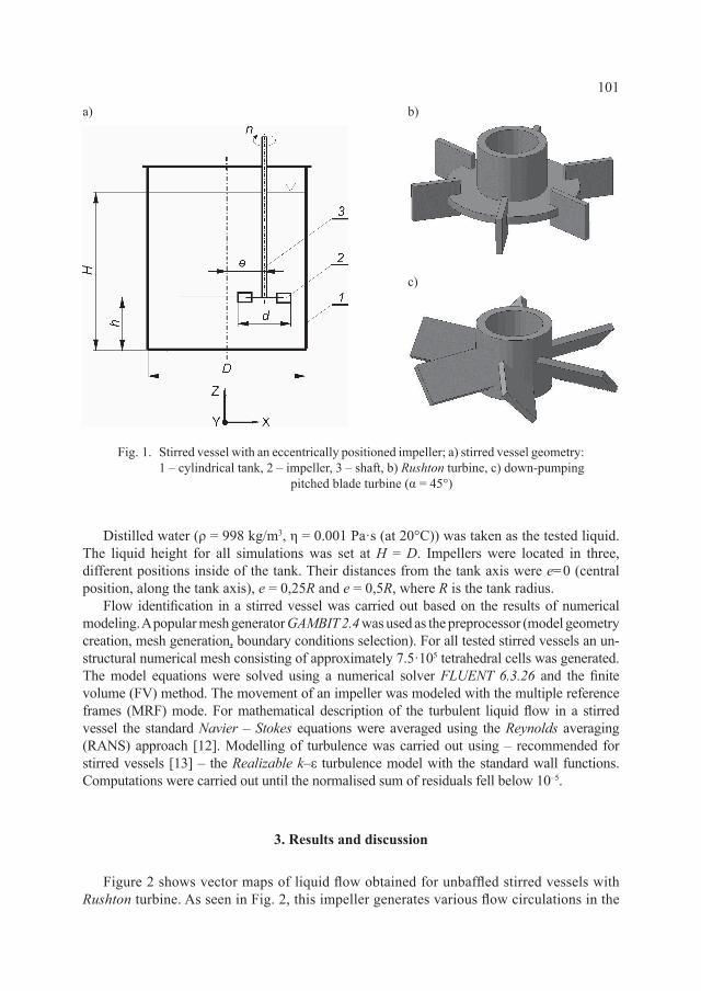
The stirred vessel used in the numerical investigations is shown in Figure 1. It consisted of an unbaffled cylindrical tank 1 (internal diameter D = 0.286 m) with a flat bottom, and a single, high-speed impeller 2 located inside of the tank. Two different types of turbine impellers were examined: the standard Rushton turbine (Fig. 1b), generating radial circulation and the down-pumping pitched blade turbine (blade angle α = 45°) (Fig. 1c), inducing axial flow. The impellers had the same diameter d = D/3 and the impeller off-bottom clearance was set at h = d. The impellers rotated clockwise at n = 300 [1/min], in a range of fully turbulent flows (Rem ≈ 4.5·104).
101
Distilled water (ρ = 998 kg/m3, η = 0.001 Pa·s (at 20°C)) was taken as the tested liquid. The liquid height for all simulations was set at H = D. Impellers were located in three, different positions inside of the tank. Their distances from the tank axis were e=0 (central position, along the tank axis), e = 0,25R and e = 0,5R, where R is the tank radius.
Flow identification in a stirred vessel was carried out based on the results of numerical modeling. A popular mesh generator GAMBIT 2.4 was used as the preprocessor (model geometry creation, mesh generation, boundary conditions selection). For all tested stirred vessels an un-structural numerical mesh consisting of approximately 7.5·105 tetrahedral cells was generated. The model equations were solved using a numerical solver FLUENT 6.3.26 and the finite volume (FV) method. The movement of an impeller was modeled with the multiple reference frames (MRF) mode. For mathematical description of the turbulent liquid flow in a stirred vessel the standard Navier – Stokes equations were averaged using the Reynolds averaging (RANS) approach [12]. Modelling of turbulence was carried out using – recommended for stirred vessels [13] – the Realizable k–ε turbulence model with the standard wall functions. Computations were carried out until the normalised sum of residuals fell below 10–5.
3. Results and discussion
Figure 2 shows vector maps of liquid flow obtained for unbaffled stirred vessels with Rushton turbine. As seen in Fig. 2, this impeller generates various flow circulations in the
Fig. 1. Stirred vessel with an eccentrically positioned impeller; a) stirred vessel geometry: 1 – cylindrical tank, 2 – impeller, 3 – shaft, b) Rushton turbine, c) down-pumping
pitched blade turbine (α = 45°)
a) b)
c)

102
vessels, depending on its eccentricity. When the impeller is located at the tank axis (e = 0), the liquid flow is symmetric with visible radial impeller discharge streams towards tank walls. The most intensive flow is observed at the impeller level, with two, independent circulation loops above and below the impeller. Insignificant displacement of shaft towards tank wall (e = 0.25R) causes changes in circulation. The flow becomes unsymmetrical and the main liquid stream is deflected to the bottom, as was the case for axial impellers. Circulation loops are deformed. For the most eccentricity (e = 0.5R), a large, distinct loop behind an impeller is generated, as well as small ones in the gap between the impeller and tank wall.
Interesting observations were made on the basis of analysis of liquid free-surface. As shown in Figure 2 (bottom row), the impeller displacement causes an introduction of an additional large-scale vortex, which is a circular (e = 0.25R) or elliptical in shape (e = 0.5R), and located opposite to impeller.
For precise and exact analysis of this phenomenon, the Q-criterion [14] was used. The criterion is defined by:
(1)
Fig. 2. Vector maps of liquid flow in a stirred vessel with an eccentrically positioned Rushton turbine: vertical cross-section plane (top row); horizontal cross-section plane on the liquid free-surface
(bottom row)
e = 0 e = 0.25R e = 0.5R
Q S= −
>
12
02 2Ω

103
where: S – is the rate-of-strain tensor, Ω – is the vorticity tensor.
It is used to identify the location of vortex cores in the whole (3D) volume of a stirred vessel. Sample iso-surfaces of Q-criterion determined for the stirred vessel with Rushton turbine are presented in Fig. 3.
Fig. 3. Iso-surfaces of Q-criterion for stirred vessel with Rushton turbine a) e = 0, b) e = 0.25R, c) e = 0.5R (Q = 15 [s–2])
a) b) c)
The visualizations presented above confirm the tendencies described above. First of all, the rotation of the whole liquid volume in the stirred vessel with a centrally positioned impeller (Fig. 3a). At this impeller location we can see a large-scale vortex around the shaft and under the impeller, as well as ring vortex cores representing circulation loops. Meanwhile, for eccentrically positioned impellers, a large-scale vortex involving the region from the free-surface to the impeller zone is seen (Fig. 3b, c). Smaller scale, unsymmetrical vortices are seen in zones around the impeller with irregular vortical structures behind the blades.
Somewhat different changes in flow circulation were observed for a stirred vessel equipped with an axial impeller, the pitched blade turbine. In this case, for impeller location at the tank axis (Fig. 4 e = 0), it generates symmetrical axial flow with shaped circulation loops; impeller discharge streams are inclined towards the tank bottom. The eccentricity of impeller (Fig. 4 e = 0.25R, e = 0.5R) changes a flow regime. An intensive liquid circulation is observed in the top (above impeller) part of the vessel, with small vortices generated under the impeller. The above changes in flow circulation confirmed visualizations presented in Fig. 5. As with the radial impeller, the eccentrically located pitched blade turbine induces a large-scale vortex in the opposite part of the vessel. An interesting vortex formation is observed for eccentricity e = 0.5R (Fig. 5 e = 0.5R). In this case, at the top part of the tank, the main vortex splits into two smaller ones and one of them is directed not to free-surface but to the tank wall.

104e = 0 e = 0.25R e = 0.5R
Fig. 4. Vector maps of liquid flow in a stirred vessel with an eccentrically positioned pitched blade turbine: vertical cross-section plane (top row); horizontal cross-section plane on the liquid free-
surface (bottom row)
a) b) c)
Fig. 5. Iso-surfaces of Q-criterion for stirred vessel with pitched blade turbine a) e = 0, b) e = 0.25R, c) e = 0.5R (Q = 10 [s–2])
105
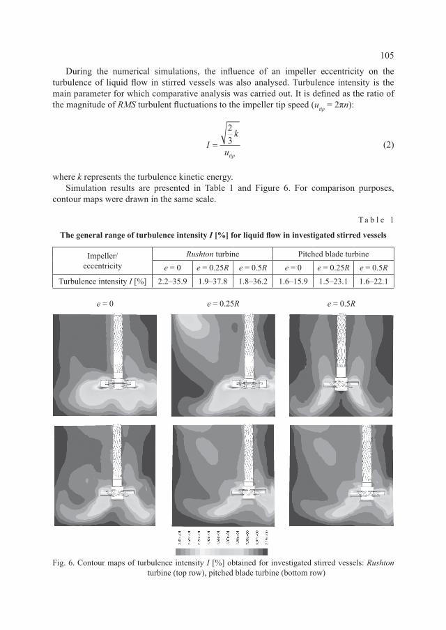
During the numerical simulations, the influence of an impeller eccentricity on the turbulence of liquid flow in stirred vessels was also analysed. Turbulence intensity is the main parameter for which comparative analysis was carried out. It is defined as the ratio of the magnitude of RMS turbulent fluctuations to the impeller tip speed (utip = 2πn):
(2)
where k represents the turbulence kinetic energy. Simulation results are presented in Table 1 and Figure 6. For comparison purposes,
contour maps were drawn in the same scale.
T a b l e 1
The general range of turbulence intensity I [%] for liquid flow in investigated stirred vessels
Impeller/eccentricity
Rushton turbine Pitched blade turbinee = 0 e = 0.25R e = 0.5R e = 0 e = 0.25R e = 0.5R
Turbulence intensity I [%] 2.2–35.9 1.9–37.8 1.8–36.2 1.6–15.9 1.5–23.1 1.6–22.1
Ik
utip=
23
e = 0 e = 0.25R e = 0.5R
Fig. 6. Contour maps of turbulence intensity I [%] obtained for investigated stirred vessels: Rushton turbine (top row), pitched blade turbine (bottom row)
106
The presented maps confirm a significant influence of the impeller location on the liquid flow turbulence inside a stirred vessel. The maximum values of turbulence intensity are observed in the vicinity of impeller blades, regardless of impeller type and its location in the vessel. Larger (even about two times) maximum values are seen for the radial impeller (Rushton turbine) (see Table.1), it confirms – well known [1, 2] – high operating efficiency of this kind of an impeller.
For both cases, the impeller eccentricity does not change turbulence conditions in the impeller zone essentially, but the flow patterns in the whole vessel are different. In the case of the Rushton turbine, an impeller displacement disturbs flow symmetry and narrows down zones of intensive turbulence. We can see a relatively broad zone of low turbulence even at the impeller level (Fig. 6 e = 0.5R RT).
For a pitched blade turbine, the regions of intensive flow close to the impeller have – in comparison with Rushton turbine – a smaller area, but impeller displacement intensifies flow in the whole vessel, including the zone under the impeller (Fig. 6 e = 0.5R PBT). For both impellers, the maximum impeller eccentricity causes more intensive flow close to the free-surface (large-scale vortex formation).
An important quantity, characterizing the mixing processes is the Newton number. It is useful for the estimation of the power consumption and also for the strength calculations of mixing vessel elements, e.g. shaft dimension, impeller design etc. For mixing, this criteria number is defined as:
(3)
where P is the power delivered to the liquid by an impeller, calculated as a product of the impeller tip speed (utip = 2πn) and torque M:
P = 2πnM (4)
For simulations, the torque values were calculated by integration of the pressure on the impeller blade.
The Newton numbers values determined numerically for the stirred vessels are presented in Table 2 and Figure 7.
T a b l e 2
The Newton number values determined in numerical simulations
Impeller/eccentricity
Rushton turbine Pitched blade turbinee = 0 e = 0.25R e = 0.5R e = 0 e = 0.25R e = 0.5R
Newton number Nem 2.64 2.95 3.03 1.24 1.37 1.45
As can be seen, an increase of impeller eccentricity causes a slight increase of Newton number values. This tendency was observed for both radial and axial impellers. A displacement
NemP
n d= 3 5ρ

107
of an impeller in a vessel from the central axis causes deformation of originally symmetric flow field and generates nonstationary vortices whose core location depend on eccentricity value. As a result, mixing power also tends to increase. A similar conclusion was drawn and described elsewhere, e.g. in [3].
Fig. 7. The values of Newton number determined on the basis of simulations for various impeller eccentricity
The presented study is the first part of research into dispersion of multiphase systems in stirred vessels with eccentrically positioned impeller. Therefore, the results mainly have a descriptive and qualitative form. In next stages of investigations, CFD simulations will be verified and validated by means of LDA measurements. It will give the complete quantitative and qualitative description of a mixing process conducted in this kind of mixing equipment.
R e f e r e n c e s
[1] Paul E.L., Atiemo-Obeng W.A., Kresta S.M., Handbook of Industrial Mixing, Wiley & Sons Inc., New Jersey 2004.
[2] Kamieński J., Mixing of multiphase systems, WNT, Warszawa 2004 (in Polish).[3] Dyląg M., Analysis of selected issues of a stirred vessel performance during dispersed
systems formation, Cracow University of Technology, Cracow 1979. [4] Nishikawa M., Ashiwake K., Hashimoto N., Nagata S., Agitation power and mixing
time in off-centering mixing, International Chemical Engineering, 19, 1979, 153–160.

108
[5] Woziwodzki S., Jędrzejczak Ł., Effect of eccentricity on laminar mixing in vessel stirred by double turbine impellers,ChemicalEngineeringResearchandDesign,89,2011, 2268–2278.
[6] WoziwodzkiS.,Broniarz-PressL.,OchowiakM.,Effect of eccentricity on transitional mixing in vessel equipped with turbine impellers,ChemicalEngineeringResearchandDesign,88,2010,1607–1614.
[7] Cudak M., Karcz J., Momentum transfer in an agitated vessel equipped with an eccentrically located HE 3 impeller, Chemical and Process Engineering, 29, 2008,1071–1082.
[8] KarczJ.,CudakM.,An effect of the type of an eccentrically located impeller on the efficiency of heat transfer process, 12th European Conference on Mixing, Bologna2006,727–734.
[9] Hall J.F., BarigouM., SimmonsM.J.H., Stitt E.H.,Comparative study of different mixing strategies in small high throughput experimentation reactors, ChemicalEngineeringScience,60,2005,2355–2368.
[10]Galletti C., Pintus S., Brunazzi E., Effect of shaft eccentricity and impeller blade thickness on the vortices features in an unbaffled vessel, Chemical EngineeringResearchandDesign,87,2009,391–400.
[11] MontanteG.,BakkerA.,PagliantiA.,MagelliF.,Effect of the shaft eccentricity on the hydrodynamics of unbaffled stirred tanks,ChemicalEngineeringScience, 61, 2006,2807–2814.
[12] JaworskiZ.,Computational fluid dynamic in chemical and process engineering,EXIT,Warszawa2005(inPolish).
[13] MarshallE.M.,BakkerA.,Computational fluid mixing,FluentInc,Lebanon2002.[14] HuntJ.C.R.,WrayA.A.,MoinP.,Eddies, streams and convergence zones in turbulent
flow,CTR-S88,1988,193–208.