Sw 4000 Config
52
Corporate Headquarters Cisco S yste ms, Inc. 17 0 West Tasman Dri ve San J ose, CA 951 34- 170 6 USA http://www.cisco.com Tel: 4 0 8 5 26 -4 0 0 0 800 553-NETS (6387) Fax: 408 526-4100 Quick Software Configuration Guide Catalyst 4500 Series Catalyst 2948 G Catalyst 294 8G-GE-TX Catalyst 2980 G Tex t Pa rt Nu mbe r: OL-4 66 8-01
Transcript of Sw 4000 Config
7/23/2019 Sw 4000 Config
http://slidepdf.com/reader/full/sw-4000-config 1/52
Corporate Headquarters
Cisco Systems, Inc.170 West Tasman DriveSan J ose, CA 95134-1706USAhttp://www.cisco.com
Tel: 408 526-4000800 553-NETS (6387)
Fax: 408 526-4100
Quick Software Configuration Guide
Catalyst 4500 Series
Catalyst 2948G
Catalyst 2948G-GE-TX
Catalyst 2980G
Text Part Number: OL-4668-01

7/23/2019 Sw 4000 Config
http://slidepdf.com/reader/full/sw-4000-config 2/52
THE SPECIFICATIONS AND INFORMATION REGARDING THE PRODUCTS IN THIS MANUAL ARE SUBJECT TO CHANGE WITHOUT NOTICE. ALL
STATEMENTS, INFORMATION, AND RECOMMENDATIONS IN THIS MANUAL ARE BELIEVED TO BE ACCURATE BUT ARE PRESENTED WITHOUT
WARRANTY OF ANY KIND, EXPRESS OR IMPLIED. USERS MUST TAKE FULL RESPONSIBILITY FOR THEIR APPLICATION OF ANY PRODUCTS.
THE SOFTWARE LICENSE AND LIMITED WARRANTY FOR THE ACCOMPANYING PRODUCT ARE SET FORTH IN THE INFORMATION PACKET THAT
SHIPPED WITH THE PRODUCT AND ARE INCORPORATED HEREIN BY THIS REFERENCE. IF YOU ARE UNABLE TO LOCATE THE SOFTWARE LICENSEOR LIMITED WARRANTY, CONTACT YOUR CISCO REPRESENTATIVE FOR A COPY.
The Cisco implementation of TCP header compression is an adaptation of a program developed by the University of Calif ornia, Berkeley (UCB) as part of UCB’s public
domain version of the UNIX operating system. All rights reserved. Copyright © 1981, Regents of the University of California.
NOTWITHSTANDING ANY OTHER WARRANTY HEREIN, ALL DOCUMENT FILES AND SOFTWARE OF THESE SUPPLIERS ARE PROVIDED “AS IS” WITH
ALL FAULTS. CISCO AND THE ABOVE-NAMED SUPPLIERS DISCLAIM ALL WARRANTIES, EXPRESSED OR IMPLIED, INCLUDING, WITHOUT
LIMITATION, THOSE OF MERCHANTABILITY, FITNESS FOR A PARTICULAR PURPOSE AND NONINFRINGEMENT OR ARISING FROM A COURSE OF
DEALING, USAGE, OR TRADE PRACTICE.
IN NO EVENT SHALL CISCO OR ITS SUPPLIERS BE LIABLE FOR ANY INDIRECT, SPECIAL, CONSEQUENTIAL, OR INCIDENTAL DAMAGES, INCLUDING,
WITHOUT LIMITATION, LOST PROFITS OR LOSS OR DAMAGE TO DATA ARISING OUT OF THE USE OR INABILITY TO USE THIS MANUAL, EVEN IF CISCO
OR ITS SUPPLIERS HAVE BEEN ADVISED OF THE POSSIBILITY OF SUCH DAMAGES.
Quick Software Configuration Guide—Catalyst 4500 Series, Catalyst 2 948G, Catalyst 2948G-GE-TX, Catalyst 2980G
Copyright © 2003, Cisco Systems, Inc.
All rights reserved.
CCIP, CCSP, the Cisco Arrow logo, the Cisco Powered Network mark, Cisco Unity, Follow Me Browsing, FormShare, and StackWise are trademarks of Cisco Systems, Inc.;
Changing the Way We Work, Live, Play, and Learn, and iQuick Study are service marks of Cisco Systems, Inc.; and Aironet, ASIST, BPX, Catalyst, CCDA, CCDP, CCIE, CCNA,
CCNP, Cisco, the Cisco Certified Internetwork Expert logo, Cisco IOS, the Cisco IOS logo, Cisco Press, Cisco Systems, Cisco Systems Capital, the Cisco Systems logo,Empowering the Internet Generation, Enterprise/Solver, EtherChannel, EtherSwitch, Fast Step, GigaStack, Internet Quotient, IOS, IP/TV, iQ Expertise, the iQ logo, iQ Net
Readiness Scorecard, LightStream, MGX, MICA, the Networkers logo, Networking Academy, Network Registrar,Packet , PIX, Post-Routing, Pre-Routing, RateMUX, Registrar,
ScriptShare, SlideCast, SMARTnet, StrataView Plus, Stratm, SwitchProbe, TeleRouter, The Fastest Way to Increase Your Internet Quotient, TransPath, and VCO are registered
trademarks of Cisco Systems, Inc. and/or its affiliates in the U.S. and certain other countries.
All other trademarks mentioned in this document or Web site are the property of their respective owners. The use of the word partner does not imply a partnership relationship
between Cisco and any other company. (0304R)
7/23/2019 Sw 4000 Config
http://slidepdf.com/reader/full/sw-4000-config 3/52
ii i
Quick Software Configuration Guide—Catalyst 4500 Series, Catalyst 2948G, Catalyst 2948G-GE-TX, Catalyst 2980G
OL-4668-01
C O N T E N T S
Preface v
Audience v
Organization v
Related Documentation vi
Conventions vi
Obtaining Documentation vii
Cisco.com vii
Documentation CD-ROM vii
Ordering Documentation viiDocumentati on Feedback viii
Obtaining Technical Assistance viii
Cisco TAC Websit e viii
Opening a TAC Case viii
TAC Case Priority Defini tions ix
Obtaining Additional Publications and Information ix
CHA P T ER 1 Basic Software Configuration 1-1
Preparing to Configure the Swi tch 1-1
Establishing a Console Port Connection 1-1
Setting t he Swit ch IP Configurati on 1-3
Configuring Swit ch Ports 1-4
CHA P T ER 2 Configuring VLANs 2-1
Configuring VLAN Trunking Protocol 2-1
Configure t he Sw itch as a VTP Server 2-2
Configure t he Sw itch as a VTP Client 2-2
Configure the Sw itch as VTP Transparent 2-3
Configuring VLAN s 2-3
Create VLAN s 2-4
Assign Sw itch Ports to VLAN s 2-5
7/23/2019 Sw 4000 Config
http://slidepdf.com/reader/full/sw-4000-config 4/52
Contents
iv
Quick Software Configuration Guide—Catalyst 4500 Series, Catalyst 2948G, Catalyst 2948G-GE-TX, Catalyst 2980G
OL-4668-01
CHA P T ER 3 Configuring EtherChannel andVLAN Trunks 3-1
Configuring EtherChannel 3-1
Configuring VLAN Trunks 3-2
CHA P T ER 4 Administering the Switch 4-1
Configuring t he Global System Sett ings 4-1
Configuring the Login Banner 4-2
Configuring DN S 4-3
M anaging Configurati on Files 4-4
Displaying the Current Configuration 4-4
Backing Up t he Current Configuration 4-4
Configuring t he Swi tch Using a Backup Configuration 4-5
M anaging System Images 4-5
W orking w ith the Flash File System 4-7
CHA P T ER 5 Monitoring the Switch 5-1
Checking System Stat us 5-1
Checking M odule Stat us 5-2
Checking Port Status 5-3
Checking Port Capabiliti es 5-4
Checking Netw ork Connectivity 5-5
Displaying Spanning Tree Informati on 5-5
Displaying Neighbor Information 5-6
Displaying the Forw arding Table 5-7
Displaying User Sessions 5-8
Displaying Version Informatio n 5-8
CHA P T ER 6 Default Configurations 6-1
Default Global System Configurat ion 6-1
Default Switch Port Configuration6-2
Default VTP Configurat ion 6-2
Default VLAN Configuration 6-3
Default EtherChannel and VLAN Trunk Configurati on 6-3
I N D E X
7/23/2019 Sw 4000 Config
http://slidepdf.com/reader/full/sw-4000-config 5/52
v
Quick Software Configuration Guide—Catalyst 4500 Series, Catalyst 2948G, Catalyst 2948G-GE-TX, Catalyst 2980G
OL-4668-01
Preface
This preface describes who should read this Quick Software Configuration Guide, how it is organized,
and its document conventions.
AudienceThis guide is intended for switch administrators who are familiar with Ethernet, Fast Ethernet, or Gigabit
Ethernet LAN switches but may not have experience configuring Catalyst 4500 series, 2948G,
2948G-GE-TX, and 2980G switches.
For complete software configuration information, refer to the Software Configuration Guide and the
Command Reference publications for your switch.
OrganizationThis guide is organized as follows:
Chapter Title Description
Chapter 1 Basic Software
Configuration
Describes how to configure the switch for basic network
connectivity
Chapter 2 Configuring VLANs Describes how to configure the VLAN Trunking Protocol
(VTP) and virtual LANs (VLANs)
Chapter 3 Configuring EtherChannel
and VLAN Trunks
Describes how to configure Fast and Gigabit EtherChannel
port bundles and VLAN trunks
Chapter 4 Administering the Switch Describes how to perform basic switch administration and
maintenance
Chapter 5 Monitoring the Switch Describes how to monitor the switch using a variety of
commands
Chapter 6 Default Configurations Lists default configuration information for the switch
software
7/23/2019 Sw 4000 Config
http://slidepdf.com/reader/full/sw-4000-config 6/52
vi
Quick Software Configuration Guide—Catalyst 4500 Series, Catalyst 2948G, Catalyst 2948G-GE-TX, Catalyst 2980G
OL-4668-01
Related Documentation
Related Documentation
Related DocumentationThis guide does not fully describe the operation and options for the software features discussed. Refer
to the following documents for complete information:
• Release notes for your software release
• Catalyst 4500 Series, Catalyst 2948G, Catalyst 2948G-GE-TX, and Catalyst 2980G Switches
Software Configuration Guide
• Catalyst 4500 Series, Catalyst 2948G, Catalyst 2948G-GE-TX, and Catalyst 2980G Switches
Command Reference
• Catalyst 4500 Series Technical Documentation:
http://www.cisco.com/en/US/products/hw/switches/ps4324/prod_technical_documentation.html
• Catalyst 4000 Series Technical Documentation:
http://www.cisco.com/en/US/products/hw/switches/ps663/prod_technical_documentation.html
ConventionsCommand descriptions use the following conventions:
Screen examples use the following conventions:
boldface font Commands and keywords are in boldface.
italic font Arguments for which you supply values are in italics.
[ ] Elements in square brackets are optional.
{ x | y | z } Alternative keywords are grouped in braces and
separated by vertical bars.
[ x | y | z ] Optional alternative keywords are grouped in brackets
and separated by vertical bars.
screen font Terminal sessions and information the system
displays are in screen font.
boldface screen font Information you must enter is in boldface screen
font.
< > Nonprinting characters, such as passwords are in
angle brackets.
<...output truncated...> Indicates that some screen output has been removed to
preserve clarity.
7/23/2019 Sw 4000 Config
http://slidepdf.com/reader/full/sw-4000-config 7/52
vii
Quick Software Configuration Guide—Catalyst 4500 Series, Catalyst 2948G, Catalyst 2948G-GE-TX, Catalyst 2980G
OL-4668-01
Obtaining Documentation
Obtaining Documentation
Notes use the following conventions:
Note Means reader take note. Notes contain helpful suggestions or references to material not covered in the
publication.
Obtaining DocumentationCisco provides several ways to obtain documentation, technical assistance, and other technical
resources. These sections explain how to obtain technical information from Cisco Systems.
Cisco.com
You can access the most current Cisco documentation on the World Wide Web at this URL:
http://www.cisco.com/univercd/home/home.htm
You can access the Cisco website at this URL:
http://www.cisco.com
International Cisco websites can be accessed from this URL:
http://www.cisco.com/public/countries_languages.shtml
Documentation CD-ROM
Cisco documentation and additional literature are available in a Cisco Documentation CD-ROM
package, which may have shipped with your product. The Documentation CD-ROM is updated regularly
and may be more current than printed documentation. The CD-ROM package is available as a single unit
or through an annual or quarterly subscription.
Registered Cisco.com users can order a single Documentation CD-ROM (product number
DOC-CONDOCCD=) through the Cisco Ordering tool:
http://www.cisco.com/en/US/partner/ordering/ordering_place_order_ordering_tool_launch.html
All users can order annual or quarterly subscriptions through the online Subscription Store:
http://www.cisco.com/go/subscription
Ordering Documentation
You can find instructions for ordering documentation at this URL:
http://www.cisco.com/univercd/cc/td/doc/es_inpck/pdi.htm
You can order Cisco documentation in these ways:
• Registered Cisco.com users (Cisco direct customers) can order Cisco product documentation from
the Networking Products MarketPlace:
http://www.cisco.com/en/US/partner/ordering/index.shtml
7/23/2019 Sw 4000 Config
http://slidepdf.com/reader/full/sw-4000-config 8/52
viii
Quick Software Configuration Guide—Catalyst 4500 Series, Catalyst 2948G, Catalyst 2948G-GE-TX, Catalyst 2980G
OL-4668-01
Documentation Feedback
Obtaining Technical Assistance
• Nonregistered Cisco.com users can order documentation through a local account representative by
calling Cisco Systems Corporate Headquarters (California, USA.) at 408 526-7208 or, elsewhere in
North America, by calling 800 553-NETS (6387).
Documentation Feedback You can submit comments electronically on Cisco.com. On the Cisco Documentation home page, click
Feedback at the top of the page.
You can send your comments in e-mail to [email protected].
You can submit comments by using the response card (if present) behind the front cover of your
document or by writing to the following address:
Cisco Systems
Attn: Customer Document Ordering
170 West Tasman Drive
San Jose, CA 95134-9883
We appreciate your comments.
Obtaining Technical AssistanceFor all customers, partners, resellers, and distributors who hold valid Cisco service contracts, the Cisco
Technical Assistance Center (TAC) provides 24-hour, award-winning technical support services, online
and over the phone. Cisco.com features the Cisco TAC website as an online starting point for technical
assistance.
Cisco TAC Website
The Cisco TAC website (http://www.cisco.com/tac) provides online documents and tools for
troubleshooting and resolving technical issues with Cisco products and technologies. The Cisco TAC
website is available 24 hours a day, 365 days a year.
Accessing all the tools on the Cisco TAC website requires a Cisco.com user ID and password. If you
have a valid service contract but do not have a login ID or password, register at this URL:
http://tools.cisco.com/RPF/register/register.do
Opening a TAC Case
The online TAC Case Open Tool (http://www.cisco.com/tac/caseopen) is the fastest way to open P3 and
P4 cases. (Your network is minimally impaired or you require product information). After you describeyour situation, the TAC Case Open Tool automatically recommends resources for an immediate solution.
If your issue is not resolved using these recommendations, your case will be assigned to a Cisco TAC
engineer.
For P1 or P2 cases (your production network is down or severely degraded) or if you do not have Internet
access, contact Cisco TAC by telephone. Cisco TAC engineers are assigned immediately to P1 and P2
cases to help keep your business operations running smoothly.
7/23/2019 Sw 4000 Config
http://slidepdf.com/reader/full/sw-4000-config 9/52
ix
Quick Software Configuration Guide—Catalyst 4500 Series, Catalyst 2948G, Catalyst 2948G-GE-TX, Catalyst 2980G
OL-4668-01
TAC Case Priority Definitions
Obtaining Additional Publications and Information
To open a case by telephone, use one of the following numbers:
Asia-Pacific: +61 2 8446 7411 (Australia: 1 800 805 227)
EMEA: +32 2 704 55 55
USA: 1 800 553-2447
For a complete listing of Cisco TAC contacts, go to this URL:
http://www.cisco.com/warp/public/687/Directory/DirTAC.shtml
TAC Case Priority Definitions
To ensure that all cases are reported in a standard format, Cisco has established case priority definitions
Priority 1 (P1)—Your network is “down” or there is a critical impact to your business operations. You
and Cisco will commit all necessary resources around the clock to resolve the situation.
Priority 2 (P2)—Operation of an existing network is severely degraded, or significant aspects of your
business operation are negatively affected by inadequate performance of Cisco products. You and Cisco
will commit full-time resources during normal business hours to resolve the situation.
Priority 3 (P3)—Operational performance of your network is impaired, but most business operations
remain functional. You and Cisco will commit resources during normal business hours to restore service
to satisfactory levels.
Priority 4 (P4)—You require information or assistance with Cisco product capabilities, installation, or
configuration. There is little or no effect on your business operations.
Obtaining Additional Publications and InformationInformation about Cisco products, technologies, and network solutions is available from various online
and printed sources.
• The Cisco Product Catalog describes the networking products offered by Cisco Systems, as well asordering and customer support services. Access the Cisco Product Catalog at this URL:
http://www.cisco.com/en/US/products/products_catalog_links_launch.html
• Cisco Press publishes a wide range of networking publications. Cisco suggests these titles for new
and experienced users: Internetworking Terms and Acronyms Dictionary, Internetworking
Technology Handbook, Internetworking Troubleshooting Guide, and the Internetworking Design
Guide. For current Cisco Press titles and other information, go to Cisco Press online at this URL:
http://www.ciscopress.com
• Packet magazine is the Cisco quarterly publication that provides the latest networking trends,
technology breakthroughs, and Cisco products and solutions to help industry professionals get the
most from their networking investment. Included are networking deployment and troubleshooting
tips, configuration examples, customer case studies, tutorials and training, certification information,and links to numerous in-depth online resources. You can access Packet magazine at this URL:
http://www.cisco.com/go/packet
• iQ Magazine is the Cisco bimonthly publication that delivers the latest information about Internet
business strategies for executives. You can access iQ Magazine at this URL:
http://www.cisco.com/go/iqmagazine
7/23/2019 Sw 4000 Config
http://slidepdf.com/reader/full/sw-4000-config 10/52
x
Quick Software Configuration Guide—Catalyst 4500 Series, Catalyst 2948G, Catalyst 2948G-GE-TX, Catalyst 2980G
OL-4668-01
Obtaining Additional Publications and Information
Obtaining Additional Publications and Information
• Internet Protocol Journal is a quarterly journal published by Cisco Systems for engineering
professionals involved in designing, developing, and operating public and private internets and
intranets. You can access the Internet Protocol Journal at this URL:
http://www.cisco.com/en/US/about/ac123/ac147/about_cisco_the_internet_protocol_journal.html
• Training—Cisco offers world-class networking training. Current offerings in network training are
listed at this URL:
http://www.cisco.com/en/US/learning/index.html
7/23/2019 Sw 4000 Config
http://slidepdf.com/reader/full/sw-4000-config 11/52
C H A P T E R
1-1
Quick Software Configuration Guide—Catalyst 4500 Series, Catalyst 2948G, Catalyst 2948G-GE-TX, Catalyst 2980G
OL-4668-01
1
Basic Software Configuration
Very little configuration is required to establish basic connectivity to the switch. This section describes
the basic tasks that you need to get your switch up and running:
Step1 Preparing to Configure the Switch—Gather the information that you need to configure the switch.
Step2 Establishing a Console Port Connection—Connect to the switch through the console port to access thecommand-line interface (CLI).
Step3 Setting the Switch IP Configuration—Assign an IP address, subnet mask, and default gateway to the
switch interface.
Step4 Configuring Switch Ports—Make sure that the switch ports are properly configured to communicate with
connected devices.
Preparing to Configure the SwitchBefore you configure the switch, make sure that the chassis, switching modules, and power supplies are
installed and cabled to specification. Refer to the hardware documentation for your switch for
information on installation.
Before you begin configuring the switch, you should gather the following information:
• A map or diagram of your network topology showing how the switch will be used in the network.
• The IP address and subnet mask for the switch. You will assign this address to the in-band (sc0)
interface on the switch.
• The IP address of the default gateway for the network (typically, the IP address of a router that is
connected to the same network).
Establishing a Console Port ConnectionConnecting a terminal to the supervisor engine console port allows you to access the switch CLI before
the switch is configured and connected to the network.
Refer to the hardware documentation for your switch model for information on connecting a terminal to
the console port.
7/23/2019 Sw 4000 Config
http://slidepdf.com/reader/full/sw-4000-config 12/52
1-2
Quick Software Configuration Guide—Catalyst 4500 Series, Catalyst 2948G, Catalyst 2948G-GE-TX, Catalyst 2980G
OL-4668-01
Chapter1 Basic Software Configuration
Establishing a Console Port Connection
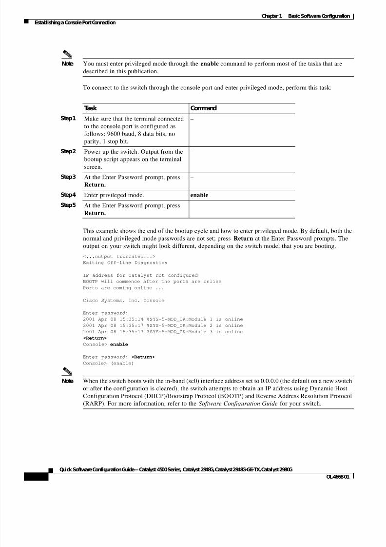
Note You must enter privileged mode through the enable command to perform most of the tasks that are
described in this publication.
To connect to the switch through the console port and enter privileged mode, perform this task:
This example shows the end of the bootup cycle and how to enter privileged mode. By default, both the
normal and privileged mode passwords are not set; press Return at the Enter Password prompts. The
output on your switch might look different, depending on the switch model that you are booting.
<...output truncated...>
Exiting Off-line Diagnostics
IP address for Catalyst not configured
BOOTP will commence after the ports are online
Ports are coming online ...
Cisco Systems, Inc. Console
Enter password:
2001 Apr 08 15:35:14 %SYS-5-MOD_OK:Module 1 is online
2001 Apr 08 15:35:17 %SYS-5-MOD_OK:Module 2 is online
2001 Apr 08 15:35:17 %SYS-5-MOD_OK:Module 3 is online
<Return>
Console> enable
Enter password: <Return>
Console> (enable)
Note When the switch boots with the in-band (sc0) interface address set to 0.0.0.0 (the default on a new switchor after the configuration is cleared), the switch attempts to obtain an IP address using Dynamic Host
Configuration Protocol (DHCP)/Bootstrap Protocol (BOOTP) and Reverse Address Resolution Protocol
(RARP). For more information, refer to the Software Configuration Guide for your switch.
Task Command
Step1 Make sure that the terminal connected
to the console port is configured as
follows: 9600 baud, 8 data bits, no
parity, 1 stop bit.
–
Step2 Power up the switch. Output from the
bootup script appears on the terminal
screen.
–
Step3 At the Enter Password prompt, press
Return.
–
Step4 Enter privileged mode. enable
Step5 At the Enter Password prompt, press
Return.
–
7/23/2019 Sw 4000 Config
http://slidepdf.com/reader/full/sw-4000-config 13/52
1-3
Quick Software Configuration Guide—Catalyst 4500 Series, Catalyst 2948G, Catalyst 2948G-GE-TX, Catalyst 2980G
OL-4668-01
Chapter1 Basic Software Configuration
Setting the Switch IP Configuration
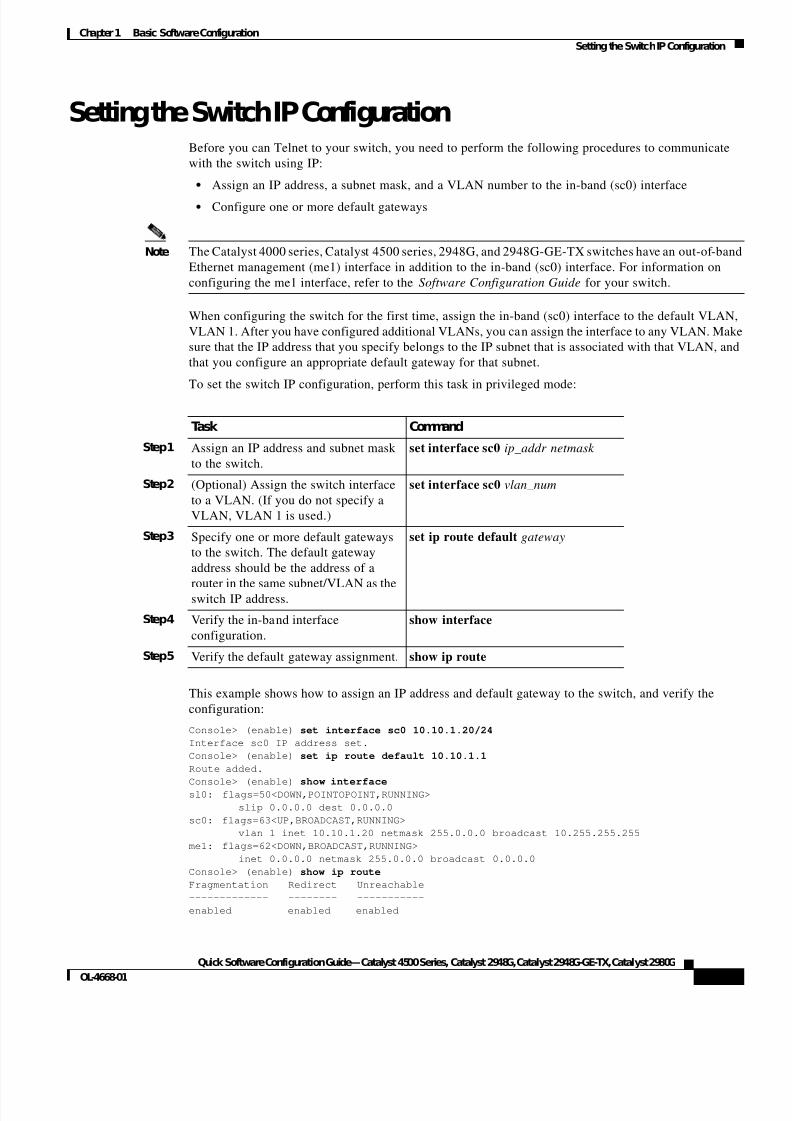
Setting the Switch IP ConfigurationBefore you can Telnet to your switch, you need to perform the following procedures to communicate
with the switch using IP:
• Assign an IP address, a subnet mask, and a VLAN number to the in-band (sc0) interface
• Configure one or more default gateways
Note The Catalyst 4000 series, Catalyst 4500 series, 2948G, and 2948G-GE-TX switches have an out-of-band
Ethernet management (me1) interface in addition to the in-band (sc0) interface. For information on
configuring the me1 interface, refer to the Software Configuration Guide for your switch.
When configuring the switch for the first time, assign the in-band (sc0) interface to the default VLAN,
VLAN 1. After you have configured additional VLANs, you can assign the interface to any VLAN. Make
sure that the IP address that you specify belongs to the IP subnet that is associated with that VLAN, and
that you configure an appropriate default gateway for that subnet.
To set the switch IP configuration, perform this task in privileged mode:
This example shows how to assign an IP address and default gateway to the switch, and verify the
configuration:
Console> (enable) set interface sc0 10.10.1.20/24
Interface sc0 IP address set.
Console> (enable) set ip route default 10.10.1.1
Route added.
Console> (enable) show interfacesl0: flags=50<DOWN,POINTOPOINT,RUNNING>
slip 0.0.0.0 dest 0.0.0.0
sc0: flags=63<UP,BROADCAST,RUNNING>
vlan 1 inet 10.10.1.20 netmask 255.0.0.0 broadcast 10.255.255.255
me1: flags=62<DOWN,BROADCAST,RUNNING>
inet 0.0.0.0 netmask 255.0.0.0 broadcast 0.0.0.0
Console> (enable) show ip route
Fragmentation Redirect Unreachable
------------- -------- -----------
enabled enabled enabled
Task Command
Step1 Assign an IP address and subnet mask
to the switch.
set interface sc0 ip_addr netmask
Step2 (Optional) Assign the switch interface
to a VLAN. (If you do not specify a
VLAN, VLAN 1 is used.)
set interface sc0 vlan_num
Step3 Specify one or more default gateways
to the switch. The default gateway
address should be the address of a
router in the same subnet/VLAN as theswitch IP address.
set ip route default gateway
Step4 Verify the in-band interface
configuration.
show interface
Step5 Verify the default gateway assignment. show ip route
7/23/2019 Sw 4000 Config
http://slidepdf.com/reader/full/sw-4000-config 14/52
1-4
Quick Software Configuration Guide—Catalyst 4500 Series, Catalyst 2948G, Catalyst 2948G-GE-TX, Catalyst 2980G
OL-4668-01
Chapter1 Basic Software Configuration
Configuring Switch Ports
The primary gateway: 10.10.1.1
Destination Gateway RouteMask Flags Use Interface
--------------- --------------- ---------- ----- -------- ---------
default 10.10.1.1 0x0 UG 0 sc0
10.0.0.0 10.10.1.20 0xff000000 U 11 sc0
Console> (enable)
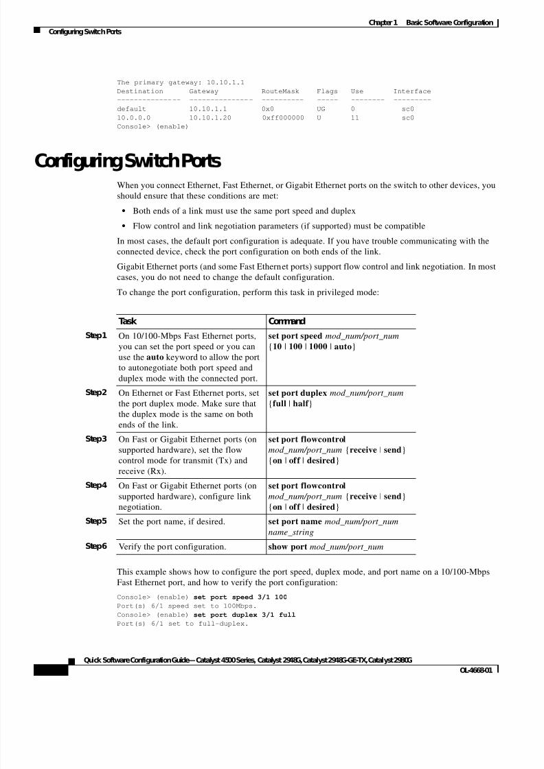
Configuring Switch PortsWhen you connect Ethernet, Fast Ethernet, or Gigabit Ethernet ports on the switch to other devices, you
should ensure that these conditions are met:
• Both ends of a link must use the same port speed and duplex
• Flow control and link negotiation parameters (if supported) must be compatible
In most cases, the default port configuration is adequate. If you have trouble communicating with the
connected device, check the port configuration on both ends of the link.
Gigabit Ethernet ports (and some Fast Ethernet ports) support flow control and link negotiation. In mostcases, you do not need to change the default configuration.
To change the port configuration, perform this task in privileged mode:
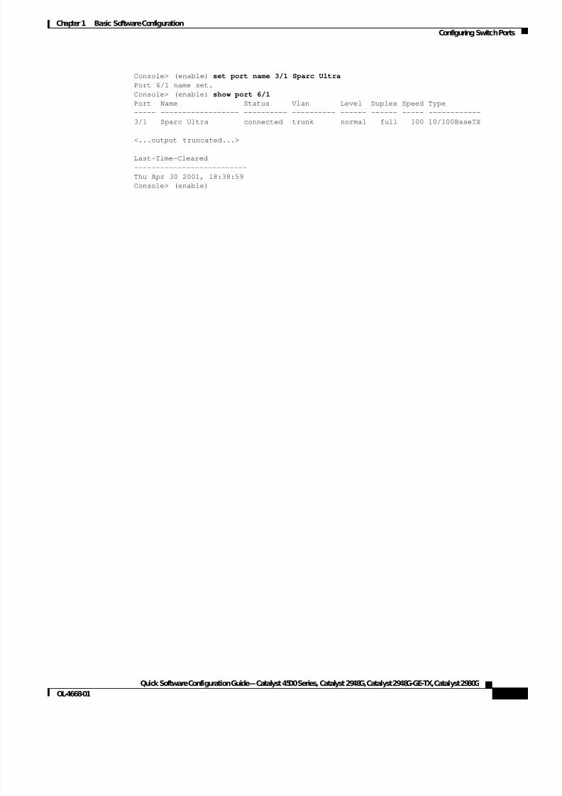
This example shows how to configure the port speed, duplex mode, and port name on a 10/100-Mbps
Fast Ethernet port, and how to verify the port configuration:
Console> (enable) set port speed 3/1 100
Port(s) 6/1 speed set to 100Mbps.
Console> (enable) set port duplex 3/1 full
Port(s) 6/1 set to full-duplex.
Task Command
Step1 On 10/100-Mbps Fast Ethernet ports,
you can set the port speed or you can
use the auto keyword to allow the port
to autonegotiate both port speed and
duplex mode with the connected port.
set port speed mod_num/port_num
{10 | 100 | 1000 | auto}
Step2 On Ethernet or Fast Ethernet ports, set
the port duplex mode. Make sure thatthe duplex mode is the same on both
ends of the link.
set port duplex mod_num/port_num
{full | half }
Step3 On Fast or Gigabit Ethernet ports (on
supported hardware), set the flow
control mode for transmit (Tx) and
receive (Rx).
set port flowcontrol
mod_num/port_num {receive | send}
{on | off | desired}
Step4 On Fast or Gigabit Ethernet ports (on
supported hardware), configure link
negotiation.
set port flowcontrol
mod_num/port_num {receive | send}
{on | off | desired}
Step5 Set the port name, if desired. set port name mod_num/port_num
name_string
Step6 Verify the port configuration. show port mod_num/port_num
7/23/2019 Sw 4000 Config
http://slidepdf.com/reader/full/sw-4000-config 15/52
1-5
Quick Software Configuration Guide—Catalyst 4500 Series, Catalyst 2948G, Catalyst 2948G-GE-TX, Catalyst 2980G
OL-4668-01
Chapter1 Basic Software Configuration
Configuring Switch Ports
Console> (enable) set port name 3/1 Sparc Ultra
Port 6/1 name set.
Console> (enable) show port 6/1
Port Name Status Vlan Level Duplex Speed Type
----- ------------------ ---------- ---------- ------ ------ ----- ------------
3/1 Sparc Ultra connected trunk normal full 100 10/100BaseTX
<...output truncated...>
Last-Time-Cleared
--------------------------
Thu Apr 30 2001, 18:38:59
Console> (enable)

7/23/2019 Sw 4000 Config
http://slidepdf.com/reader/full/sw-4000-config 16/52
1-6
Quick Software Configuration Guide—Catalyst 4500 Series, Catalyst 2948G, Catalyst 2948G-GE-TX, Catalyst 2980G
OL-4668-01
Chapter1 Basic Software Configuration
Configuring Switch Ports
7/23/2019 Sw 4000 Config
http://slidepdf.com/reader/full/sw-4000-config 17/52
C H A P T E R
2-1
Quick Software Configuration Guide—Catalyst 4500 Series, Catalyst 2948G, Catalyst 2948G-GE-TX, Catalyst 2980G
OL-4668-01
2
Configuring VLANs
To configure VLANs on the switch, perform these tasks:
Step1 Configuring VLAN Trunking Protocol—Create a VLAN Trunking Protocol (VTP) domain and set the
VTP mode on the switch.
Step2 Configuring VLANs—Create VLANs in the VTP domain and assign switch ports to those VLANs.
Configuring VLAN Trunking ProtocolVTP propagates information about the VLAN configuration throughout the switched network.
Note VTP only exchanges VLAN information over VLAN trunk links. For information on configuring trunk
links, see Chapter 3, “Configuring EtherChannel and VLAN Trunks.”
The switch can operate in any one of these three VTP modes:
• Server—VTP servers advertise their VLAN configuration to other switches in the same VTP domain
and synchronize their VLAN configuration with other switches based on advertisements received
over trunk links. The VTP server is the default mode.
• Client—VTP clients are similar to VTP servers, except that you cannot create, change, or delete
VLANs on a VTP client.
• Transparent—VTP transparent switches do not participate in VTP. A VTP transparent switch does
not advertise its VLAN configuration and does not synchronize its VLAN configuration based on
received advertisements.
Note Before you configure VLANs on the switch, you should decide whether to use VTP. If you decide to use
VTP, you need to decide whether the switch should function as a VTP client or a VTP server. If you are
connecting the switch to an existing network, make sure that your VTP configuration is compatible with
the rest of the network.

7/23/2019 Sw 4000 Config
http://slidepdf.com/reader/full/sw-4000-config 18/52
2-2
Quick Software Configuration Guide—Catalyst 4500 Series, Catalyst 2948G, Catalyst 2948G-GE-TX, Catalyst 2980G
OL-4668-01
Chapter2 Configuring VLANs
Configuring VLAN Trunking Protocol
Configure the Switch as a VTP Server
When you configure a switch as a VTP server, you must define a VTP domain before you can create
VLANs.
To configure a switch as a VTP server, perform this task in privileged mode:
This example shows how to configure a switch as a VTP server:
Console> (enable) set vtp domain BigCorp
VTP domain BigCorp modified
Console> (enable)set vtp mode serverVTP domain BigCorp modified
Console> (enable) show vtp domain
Domain Name Domain Index VTP Version Local Mode Password
-------------------------------- ------------ ----------- ----------- ----------
BigCorp 1 2 server -
Vlan-count Max-vlan-storage Config Revision Notifications
---------- ---------------- --------------- -------------
5 1023 0 disabled
Last Updater V2 Mode Pruning PruneEligible on Vlans
--------------- -------- -------- -------------------------
0.0.0.0 disabled disabled 2-1000
Console> (enable)
Configure the Switch as a VTP Client
When you configure a switch as a VTP client, you cannot configure VLANs on the switch; instead, you
configure VLANs on a VTP server in the same VTP domain as the client. The VTP client synchronizes
its VLAN configuration to the configuration of the server.
To configure a switch as a VTP client, perform this task in privileged mode:
Task Command
Step1 Assign a name to the VTP management
domain.
set vtp domain name
Step2 Set the VTP mode. set vtp mode server
Step3 Verify the VTP configuration. show vtp domain
Task Command
Step1 Assign a name to the VTP management
domain.
set vtp domain name
Step2 Set the VTP mode. set vtp mode client
Step3 Verify the VTP configuration. (It might
take a few minutes before a VTP client
learns the VTP and VLAN
configuration information from
neighboring switches.)
show vtp domain
7/23/2019 Sw 4000 Config
http://slidepdf.com/reader/full/sw-4000-config 19/52
2-3
Quick Software Configuration Guide—Catalyst 4500 Series, Catalyst 2948G, Catalyst 2948G-GE-TX, Catalyst 2980G
OL-4668-01
Chapter2 Configuring VLANs
Configuring VLANs
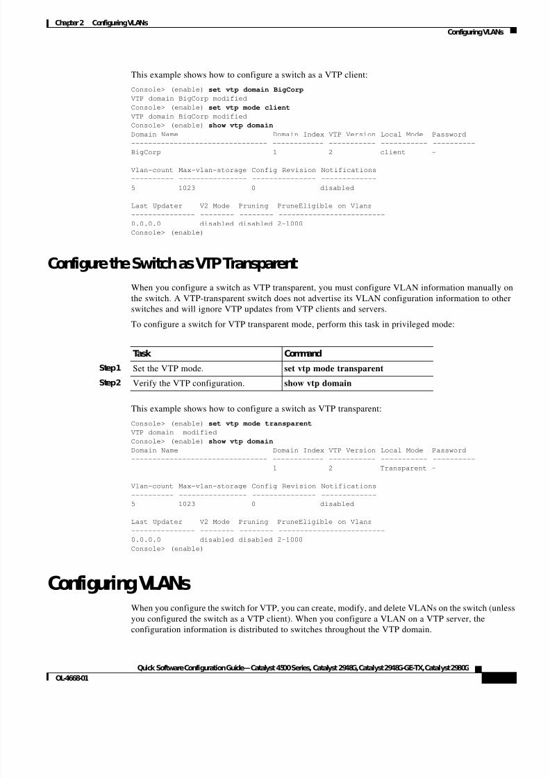
This example shows how to configure a switch as a VTP client:
Console> (enable) set vtp domain BigCorp
VTP domain BigCorp modified
Console> (enable) set vtp mode client
VTP domain BigCorp modified
Console> (enable) show vtp domain
Domain Name Domain Index VTP Version Local Mode Password-------------------------------- ------------ ----------- ----------- ----------
BigCorp 1 2 client -
Vlan-count Max-vlan-storage Config Revision Notifications
---------- ---------------- --------------- -------------
5 1023 0 disabled
Last Updater V2 Mode Pruning PruneEligible on Vlans
--------------- -------- -------- -------------------------
0.0.0.0 disabled disabled 2-1000
Console> (enable)
Configure the Switch as VTP Transparent
When you configure a switch as VTP transparent, you must configure VLAN information manually on
the switch. A VTP-transparent switch does not advertise its VLAN configuration information to other
switches and will ignore VTP updates from VTP clients and servers.
To configure a switch for VTP transparent mode, perform this task in privileged mode:
This example shows how to configure a switch as VTP transparent:
Console> (enable) set vtp mode transparent
VTP domain modified
Console> (enable) show vtp domain
Domain Name Domain Index VTP Version Local Mode Password
-------------------------------- ------------ ----------- ----------- ----------
1 2 Transparent -
Vlan-count Max-vlan-storage Config Revision Notifications
---------- ---------------- --------------- -------------
5 1023 0 disabled
Last Updater V2 Mode Pruning PruneEligible on Vlans
--------------- -------- -------- -------------------------
0.0.0.0 disabled disabled 2-1000
Console> (enable)
Configuring VLANsWhen you configure the switch for VTP, you can create, modify, and delete VLANs on the switch (unless
you configured the switch as a VTP client). When you configure a VLAN on a VTP server, the
configuration information is distributed to switches throughout the VTP domain.
Task Command
Step1 Set the VTP mode. set vtp mode transparent
Step2 Verify the VTP configuration. show vtp domain
7/23/2019 Sw 4000 Config
http://slidepdf.com/reader/full/sw-4000-config 20/52
2-4
Quick Software Configuration Guide—Catalyst 4500 Series, Catalyst 2948G, Catalyst 2948G-GE-TX, Catalyst 2980G
OL-4668-01
Chapter2 Configuring VLANs
Configuring VLANs
VTP clients and servers in the same domain update their VLAN configuration based on the advertised
configuration. VTP transparent switches do not act on VTP updates; you must manually make changes
to the VLAN configuration on such switches.
Typically, in an IP network, each VLAN is associated with a single IP subnetwork. That is, all of the
hosts in a given VLAN belong to a single subnet, use the same subnet mask, and use one or more default
gateways that are connected to that subnetwork. Stations in different VLANs cannot communicate withone another without a router configured to route between the different VLANs.
The supervisor engine software supports many VLAN types. This section describes only how to
configure Ethernet VLANs. For information about configuring other types of VLANs, refer to the
Software Configuration Guide for your switch.
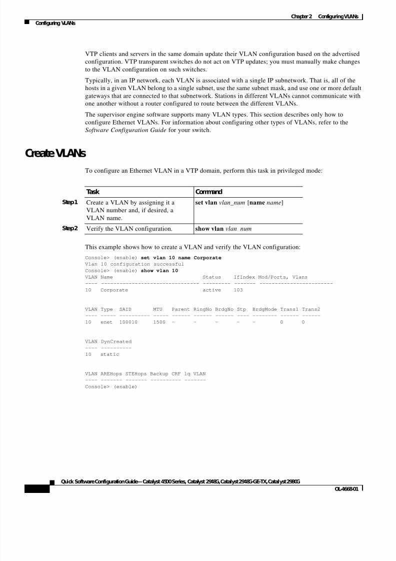
Create VLANs
To configure an Ethernet VLAN in a VTP domain, perform this task in privileged mode:
This example shows how to create a VLAN and verify the VLAN configuration:
Console> (enable) set vlan 10 name Corporate
Vlan 10 configuration successful
Console> (enable) show vlan 10
VLAN Name Status IfIndex Mod/Ports, Vlans
---- -------------------------------- --------- ------- ------------------------
10 Corporate active 103
VLAN Type SAID MTU Parent RingNo BrdgNo Stp BrdgMode Trans1 Trans2
---- ----- ---------- ----- ------ ------ ------ ---- -------- ------ ------
10 enet 100010 1500 - - - - - 0 0
VLAN DynCreated
---- ----------
10 static
VLAN AREHops STEHops Backup CRF 1q VLAN
---- ------- ------- ---------- -------
Console> (enable)
Task Command
Step1 Create a VLAN by assigning it a
VLAN number and, if desired, a
VLAN name.
set vlan vlan_num [name name]
Step2 Verify the VLAN configuration. show vlan vlan_num
7/23/2019 Sw 4000 Config
http://slidepdf.com/reader/full/sw-4000-config 21/52
2-5
Quick Software Configuration Guide—Catalyst 4500 Series, Catalyst 2948G, Catalyst 2948G-GE-TX, Catalyst 2980G
OL-4668-01
Chapter2 Configuring VLANs
Configuring VLANs
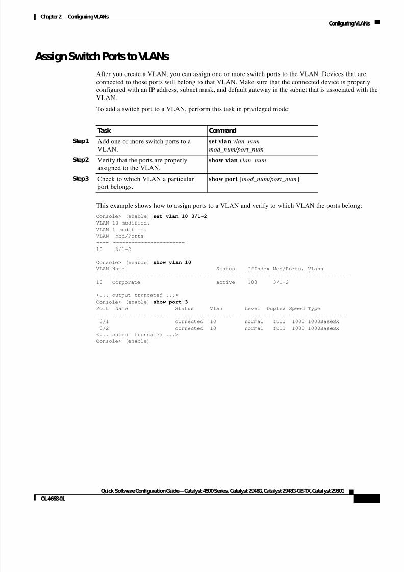
Assign Switch Ports to VLANs
After you create a VLAN, you can assign one or more switch ports to the VLAN. Devices that are
connected to those ports will belong to that VLAN. Make sure that the connected device is properly
configured with an IP address, subnet mask, and default gateway in the subnet that is associated with the
VLAN.To add a switch port to a VLAN, perform this task in privileged mode:
This example shows how to assign ports to a VLAN and verify to which VLAN the ports belong:
Console> (enable) set vlan 10 3/1-2
VLAN 10 modified.
VLAN 1 modified.
VLAN Mod/Ports
---- -----------------------
10 3/1-2
Console> (enable) show vlan 10
VLAN Name Status IfIndex Mod/Ports, Vlans
---- -------------------------------- --------- ------- ------------------------
10 Corporate active 103 3/1-2
<... output truncated ...>
Console> (enable) show port 3Port Name Status Vlan Level Duplex Speed Type
----- ------------------ ---------- ---------- ------ ------ ----- ------------
3/1 connected 10 normal full 1000 1000BaseSX
3/2 connected 10 normal full 1000 1000BaseSX
<... output truncated ...>
Console> (enable)
Task Command
Step1 Add one or more switch ports to a
VLAN.
set vlan vlan_num
mod_num/port_num
Step2 Verify that the ports are properly
assigned to the VLAN.
show vlan vlan_num
Step3 Check to which VLAN a particular
port belongs.
show port [mod_num/port_num]

7/23/2019 Sw 4000 Config
http://slidepdf.com/reader/full/sw-4000-config 22/52
2-6
Quick Software Configuration Guide—Catalyst 4500 Series, Catalyst 2948G, Catalyst 2948G-GE-TX, Catalyst 2980G
OL-4668-01
Chapter2 Configuring VLANs
Configuring VLANs
7/23/2019 Sw 4000 Config
http://slidepdf.com/reader/full/sw-4000-config 23/52
C H A P T E R
3-1
Quick Software Configuration Guide—Catalyst 4500 Series, Catalyst 2948G, Catalyst 2948G-GE-TX, Catalyst 2980G
OL-4668-01
3
Configuring EtherChannel andVLAN Trunks
To configure EtherChannel VLAN trunks on the switch, perform these tasks:
Step1 Configuring EtherChannel—Configure multiple ports between switches as a single virtual link.
Step2 Configuring VLAN Trunks—Configure the EtherChannel link as a trunk port to transport traffic for
multiple VLANs.
Configuring EtherChannelEtherChannel port bundles provide increased bandwidth between network devices by grouping multiple
Fast or Gigabit Ethernet ports into a single logical transmission path.
An EtherChannel bundle contains two or more Fast or Gigabit EtherChannel-capable ports.
EtherChannel capabilities and flexibility vary, depending on your hardware and software. Use the show
port capabilities command to determine the supported channeling capabilities on your switch.
The Port Aggregation Protocol (PAgP) negotiates EtherChannel port groups automatically. By default,
Ethernet ports are set to auto. If a group of EtherChannel ports that are set to auto is connected to a
group of ports that are set to desirable or on, PAgP automatically creates an EtherChannel connection
between those ports. For complete information on the various EtherChannel modes, refer to the Software
Configuration Guide.
You can configure ports to negotiate an EtherChannel bundle with the neighboring device automatically
(using the auto and desirable modes), or you can place the ports in on mode on both ends of the link.
Ports in on mode will not form a channel with ports in auto or desirable mode. By default, Fast and
Gigabit Ethernet ports are in auto mode.
Note There are additional configuration restrictions that are associated with EtherChannel port bundles. For
complete information, refer to the Software Configuration Guide for your switch.
7/23/2019 Sw 4000 Config
http://slidepdf.com/reader/full/sw-4000-config 24/52
3-2
Quick Software Configuration Guide—Catalyst 4500 Series, Catalyst 2948G, Catalyst 2948G-GE-TX, Catalyst 2980G
OL-4668-01
Chapter3 Configuring EtherChannel andVLAN Trunks
Configuring VLAN Trunks
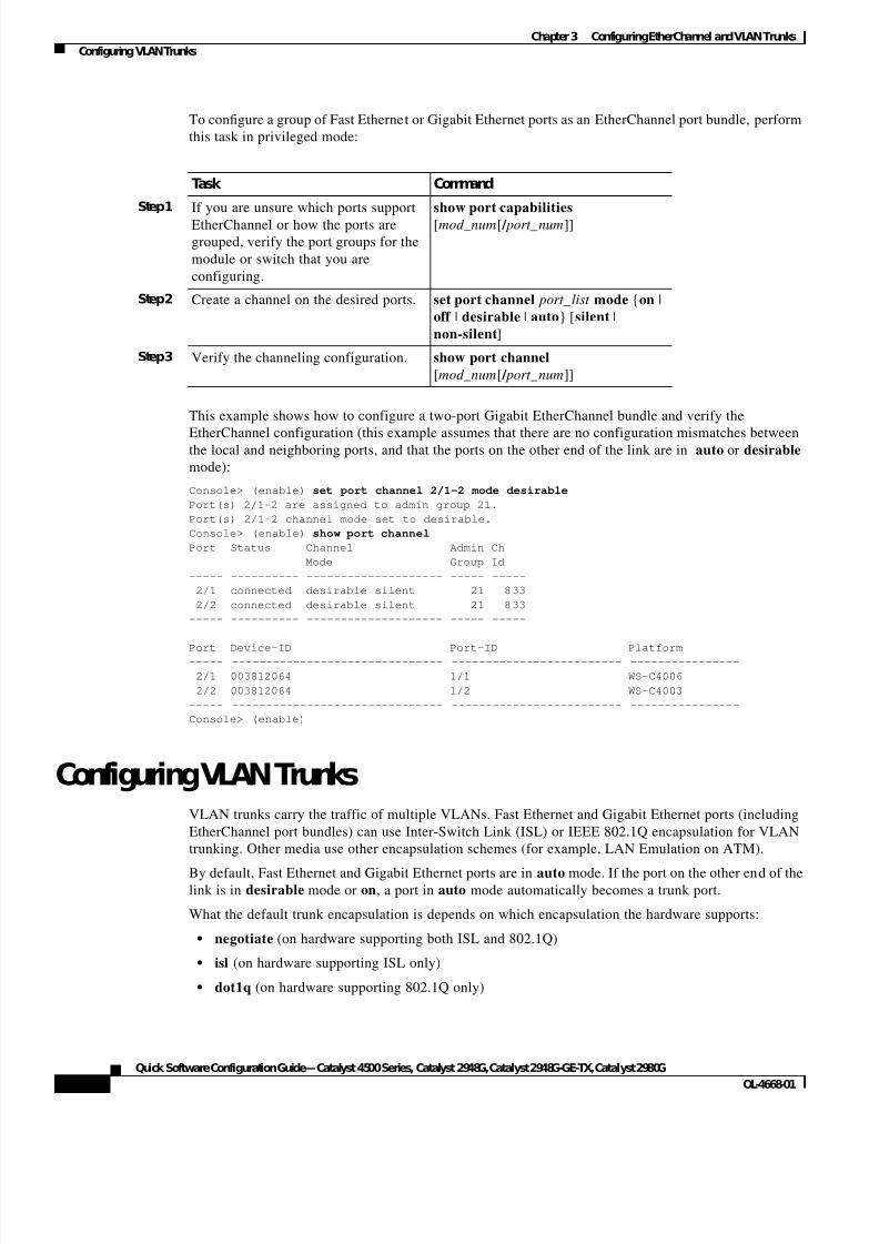
To configure a group of Fast Ethernet or Gigabit Ethernet ports as an EtherChannel port bundle, perform
this task in privileged mode:
This example shows how to configure a two-port Gigabit EtherChannel bundle and verify the
EtherChannel configuration (this example assumes that there are no configuration mismatches betweenthe local and neighboring ports, and that the ports on the other end of the link are in auto or desirable
mode):
Console> (enable) set port channel 2/1-2 mode desirable
Port(s) 2/1-2 are assigned to admin group 21.
Port(s) 2/1-2 channel mode set to desirable.
Console> (enable) show port channel
Port Status Channel Admin Ch
Mode Group Id
----- ---------- -------------------- ----- -----
2/1 connected desirable silent 21 833
2/2 connected desirable silent 21 833
----- ---------- -------------------- ----- -----
Port Device-ID Port-ID Platform
----- ------------------------------- ------------------------- ----------------
2/1 003812064 1/1 WS-C4006
2/2 003812064 1/2 WS-C4003
----- ------------------------------- ------------------------- ----------------
Console> (enable)
Configuring VLAN TrunksVLAN trunks carry the traffic of multiple VLANs. Fast Ethernet and Gigabit Ethernet ports (including
EtherChannel port bundles) can use Inter-Switch Link (ISL) or IEEE 802.1Q encapsulation for VLAN
trunking. Other media use other encapsulation schemes (for example, LAN Emulation on ATM).
By default, Fast Ethernet and Gigabit Ethernet ports are in auto mode. If the port on the other end of thelink is in desirable mode or on, a port in auto mode automatically becomes a trunk port.
What the default trunk encapsulation is depends on which encapsulation the hardware supports:
• negotiate (on hardware supporting both ISL and 802.1Q)
• isl (on hardware supporting ISL only)
• dot1q (on hardware supporting 802.1Q only)
Task Command
Step1 If you are unsure which ports support
EtherChannel or how the ports are
grouped, verify the port groups for the
module or switch that you are
configuring.
show port capabilities
[mod_num[ / port_num]]
Step2 Create a channel on the desired ports. set port channel port_list mode {on |
off | desirable | auto} [silent |
non-silent]
Step3 Verify the channeling configuration. show port channel
[mod_num[ / port_num]]
7/23/2019 Sw 4000 Config
http://slidepdf.com/reader/full/sw-4000-config 25/52
3-3
Quick Software Configuration Guide—Catalyst 4500 Series, Catalyst 2948G, Catalyst 2948G-GE-TX, Catalyst 2980G
OL-4668-01
Chapter3 Configuring EtherChannel andVLAN Trunks
Configuring VLAN Trunks
Note For complete information on the various trunk modes and encapsulation types, refer to the Software
Configuration Guide for your switch.
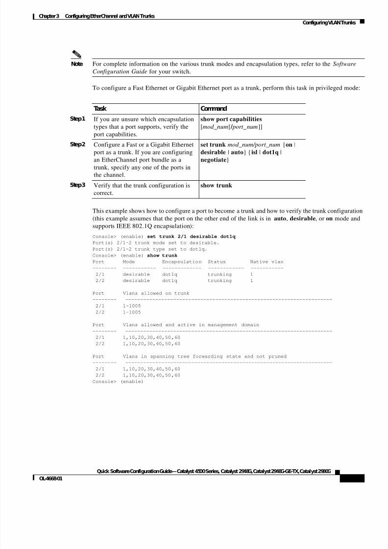
To configure a Fast Ethernet or Gigabit Ethernet port as a trunk, perform this task in privileged mode:
This example shows how to configure a port to become a trunk and how to verify the trunk configuration
(this example assumes that the port on the other end of the link is in auto, desirable, or on mode and
supports IEEE 802.1Q encapsulation):
Console> (enable) set trunk 2/1 desirable dot1q
Port(s) 2/1-2 trunk mode set to desirable.
Port(s) 2/1-2 trunk type set to dot1q.
Console> (enable) show trunk
Port Mode Encapsulation Status Native vlan
-------- ----------- ------------- ------------ -----------
2/1 desirable dot1q trunking 1
2/2 desirable dot1q trunking 1
Port Vlans allowed on trunk
-------- ---------------------------------------------------------------------
2/1 1-1005
2/2 1-1005
Port Vlans allowed and active in management domain
-------- ---------------------------------------------------------------------
2/1 1,10,20,30,40,50,60
2/2 1,10,20,30,40,50,60
Port Vlans in spanning tree forwarding state and not pruned
-------- ---------------------------------------------------------------------
2/1 1,10,20,30,40,50,60
2/2 1,10,20,30,40,50,60
Console> (enable)
Task Command
Step1 If you are unsure which encapsulation
types that a port supports, verify the
port capabilities.
show port capabilities
[mod_num[ / port_num]]
Step2 Configure a Fast or a Gigabit Ethernet
port as a trunk. If you are configuring
an EtherChannel port bundle as a
trunk, specify any one of the ports in
the channel.
set trunk mod_num/port_num {on |
desirable | auto} {isl | dot1q |
negotiate}
Step3 Verify that the trunk configuration is
correct.
show trunk

7/23/2019 Sw 4000 Config
http://slidepdf.com/reader/full/sw-4000-config 26/52
3-4
Quick Software Configuration Guide—Catalyst 4500 Series, Catalyst 2948G, Catalyst 2948G-GE-TX, Catalyst 2980G
OL-4668-01
Chapter3 Configuring EtherChannel andVLAN Trunks
Configuring VLAN Trunks
7/23/2019 Sw 4000 Config
http://slidepdf.com/reader/full/sw-4000-config 27/52
C H A P T E R
4-1
Quick Software Configuration Guide—Catalyst 4500 Series, Catalyst 2948G, Catalyst 2948G-GE-TX, Catalyst 2980G
OL-4668-01
4
Administering the Switch
These sections describe some of the common administrative tasks that you need to perform on your
switch:
• Configuring the Global System Settings—How to set system information, the time and date , and the
login and enable passwords.
• Configuring the Login Banner—How to change message-of-the-day displays.
• Configuring DNS—How to configure the switch to use the Domain Name System (DNS).
• Managing Configuration Files—How to work with switch configuration files.
• Managing System Images—How to upload and download system image files.
• Working with the Flash File System—How to use the Flash file system.
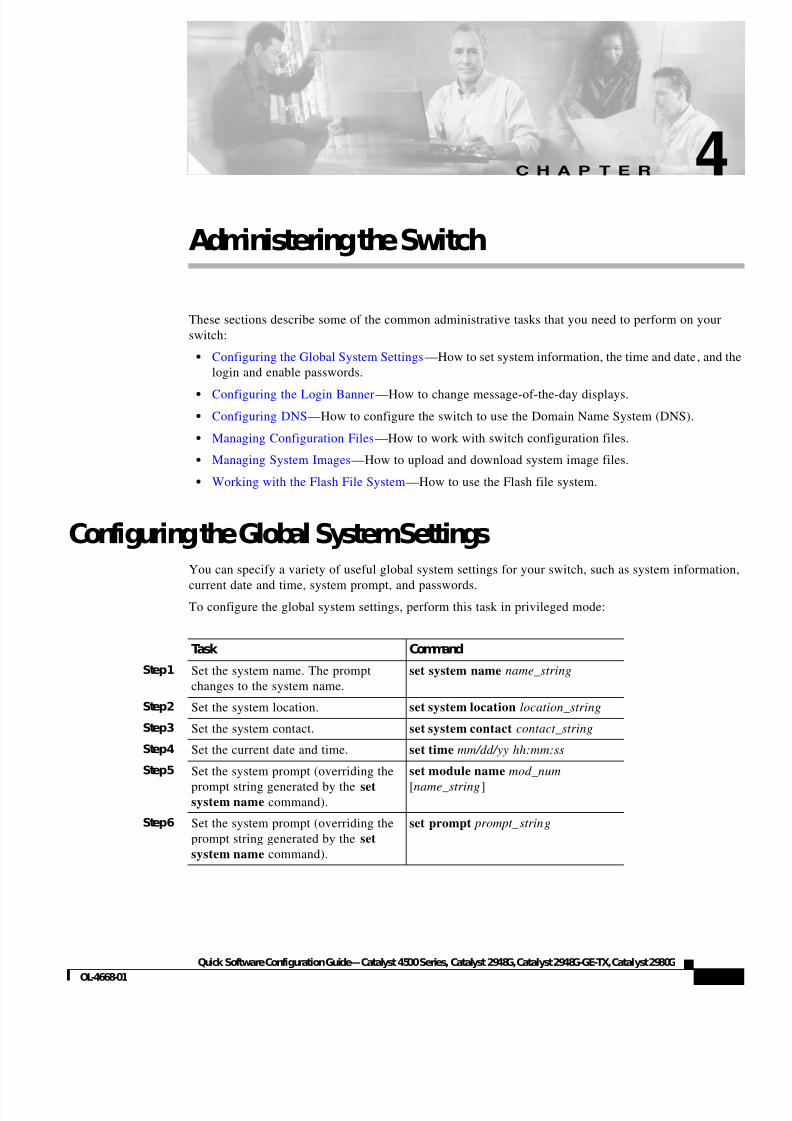
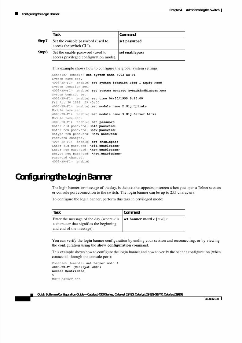
Configuring the Global SystemSettingsYou can specify a variety of useful global system settings for your switch, such as system information,
current date and time, system prompt, and passwords.To configure the global system settings, perform this task in privileged mode:
Task Command
Step1 Set the system name. The prompt
changes to the system name.
set system name name_string
Step2 Set the system location. set system location location_string
Step3 Set the system contact. set system contact contact_string
Step4 Set the current date and time. set time mm/dd/yy hh:mm:ss
Step5 Set the system prompt (overriding the
prompt string generated by the setsystem name command).
set module name mod_num
[name_string]
Step6 Set the system prompt (overriding the
prompt string generated by the set
system name command).
set prompt prompt_string
7/23/2019 Sw 4000 Config
http://slidepdf.com/reader/full/sw-4000-config 28/52
4-2
Quick Software Configuration Guide—Catalyst 4500 Series, Catalyst 2948G, Catalyst 2948G-GE-TX, Catalyst 2980G
OL-4668-01
Chapter4 Administering the Switch
Configuring the Login Banner
This example shows how to configure the global system settings:
Console> (enable) set system name 4003-ER-F1
System name set.
4003-ER-F1> (enable) set system location Bldg 1 Equip Room
System location set.
4003-ER-F1> (enable) set system contact [email protected]
System contact set.
4003-ER-F1> (enable) set time 04/30/1999 9:45:00
Fri Apr 30 1999, 09:45:00
4003-ER-F1> (enable) set module name 2 Gig Uplinks
Module name set.
4003-ER-F1> (enable) set module name 3 Gig Server Links
Module name set.
4003-ER-F1> (enable) set password
Enter old password: <old_password>
Enter new password: <new_password>
Retype new password: <new_password>
Password changed.
4003-ER-F1> (enable) set enablepass
Enter old password: <old_enablepass>
Enter new password: <new_enablepass>
Retype new password: <new_enablepass>
Password changed.
4003-ER-F1> (enable)
Configuring the Login BannerThe login banner, or message of the day, is the text that appears onscreen when you open a Telnet session
or console port connection to the switch. The login banner can be up to 255 characters.
To configure the login banner, perform this task in privileged mode:
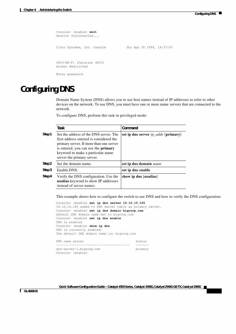
You can verify the login banner configuration by ending your session and reconnecting, or by viewingthe configuration using the show configuration command.
This example shows how to configure the login banner and how to verify the banner configuration (when
connected through the console port):
Console> (enable) set banner motd %
4003-ER-F1 (Catalyst 4003)
Access Restricted
%
MOTD banner set
Step7 Set the console password (used to
access the switch CLI).
set password
Step8 Set the enable password (used to
access privileged configuration mode).
set enablepass
Task Command
Task Command
Enter the message of the day (where c is
a character that signifies the beginning
and end of the message).
set banner motd c [text ] c
7/23/2019 Sw 4000 Config
http://slidepdf.com/reader/full/sw-4000-config 29/52
4-3
Quick Software Configuration Guide—Catalyst 4500 Series, Catalyst 2948G, Catalyst 2948G-GE-TX, Catalyst 2980G
OL-4668-01
Chapter4 Administering the Switch
Configuring DNS
Console> (enable) exit
Session Disconnected...
Cisco Systems, Inc. Console Thu Apr 30 1999, 16:37:03
4003-ER-F1 (Catalyst 4003)
Access Restricted
Enter password:
Configuring DNSDomain Name System (DNS) allows you to use host names instead of IP addresses to refer to other
devices on the network. To use DNS, you must have one or more name servers that are connected to the
network.
To configure DNS, perform this task in privileged mode:
This example shows how to configure the switch to use DNS and how to verify the DNS configuration
Console> (enable) set ip dns server 10.10.10.100
10.10.10.100 added to DNS server table as primary server.
Console> (enable) set ip dns domain bigcorp.com
Default DNS domain name set to bigcorp.com
Console> (enable) set ip dns enable
DNS is enabled
Console> (enable) show ip dns
DNS is currently enabled.
The default DNS domain name is: bigcorp.com
DNS name server status
---------------------------------------- -------
dns-server-1.bigcorp.com primary
Console> (enable)
Task Command
Step1 Set the address of the DNS server. The
first address entered is considered the
primary server. If more than one server
is entered, you can use the primary
keyword to make a particular name
server the primary server.
set ip dns server ip_addr [primary]
Step2 Set the domain name. set ip dns domain name
Step3 Enable DNS. set ip dns enable
Step4 Verify the DNS configuration. Use thenoalias keyword to show IP addresses
instead of server names.
show ip dns [noalias]
7/23/2019 Sw 4000 Config
http://slidepdf.com/reader/full/sw-4000-config 30/52
4-4
Quick Software Configuration Guide—Catalyst 4500 Series, Catalyst 2948G, Catalyst 2948G-GE-TX, Catalyst 2980G
OL-4668-01
Chapter4 Administering the Switch
Managing Configuration Files
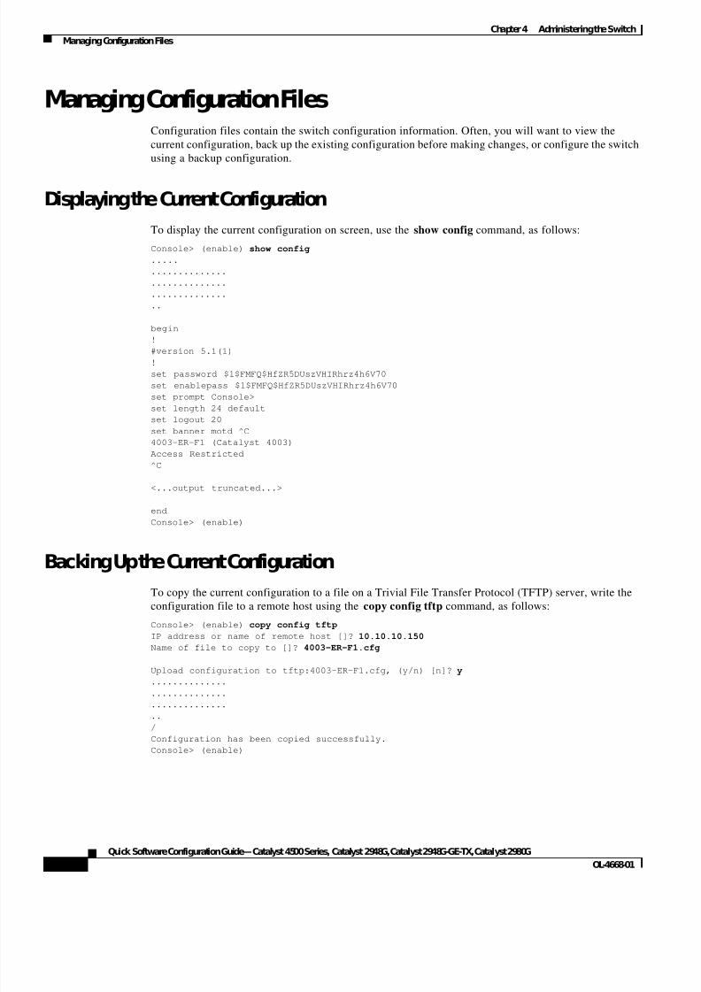
Managing Configuration FilesConfiguration files contain the switch configuration information. Often, you will want to view the
current configuration, back up the existing configuration before making changes, or configure the switch
using a backup configuration.
Displaying the Current Configuration
To display the current configuration on screen, use the show config command, as follows:
Console> (enable) show config
.....
..............
..............
..............
..
begin
!
#version 5.1(1)
!
set password $1$FMFQ$HfZR5DUszVHIRhrz4h6V70
set enablepass $1$FMFQ$HfZR5DUszVHIRhrz4h6V70
set prompt Console>
set length 24 default
set logout 20
set banner motd ^C
4003-ER-F1 (Catalyst 4003)
Access Restricted
^C
<...output truncated...>
end
Console> (enable)
Backing Up the Current Configuration
To copy the current configuration to a file on a Trivial File Transfer Protocol (TFTP) server, write the
configuration file to a remote host using the copy config tftp command, as follows:
Console> (enable) copy config tftp
IP address or name of remote host []? 10.10.10.150
Name of file to copy to []? 4003-ER-F1.cfg
Upload configuration to tftp:4003-ER-F1.cfg, (y/n) [n]? y
..............
..............
..............
..
/
Configuration has been copied successfully.
Console> (enable)

7/23/2019 Sw 4000 Config
http://slidepdf.com/reader/full/sw-4000-config 31/52
4-5
Quick Software Configuration Guide—Catalyst 4500 Series, Catalyst 2948G, Catalyst 2948G-GE-TX, Catalyst 2980G
OL-4668-01
Chapter4 Administering the Switch
Managing SystemImages
Configuring the Switch Using a Backup Configuration
To configure the switch using a configuration file on a TFTP server, copy the configuration file to a
remote host using the copy tftp config command, as follows:
Console> (enable) copy tftp config
IP address or name of remote host []? 10.10.10.150Name of file to copy from []? dns_config.cfg
Configure using tftp:dns_config.cfg (y/n) [n]? y
Finished network download. (135 bytes)
>>
>> set ip dns server 10.10.10.100 primary
10.10.10.100 added to DNS server table as primary server.
>> set ip dns enable
DNS is enabled
>> set ip dns domain bigcorp.com
Default DNS domain name set to bigcorp.com
Console> (enable)
Managing SystemImagesTo change the system software image on your switch, obtain the appropriate software image file for your
switch, place it on a TFTP server, and use the procedure for your switch to copy the image to the switch
and reboot using the new image.
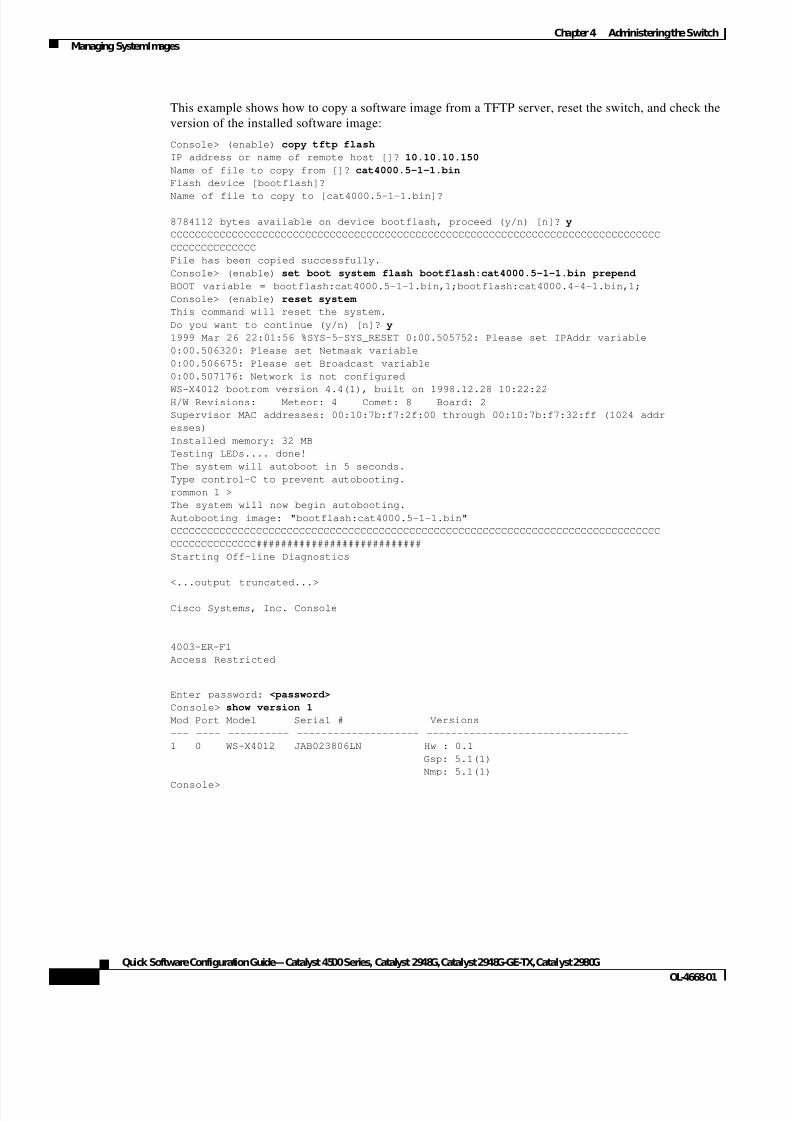
To copy a system software image from a TFTP server and reboot the switch using the new software
image, perform this task in privileged mode:
Task Command
Step1 Copy a system image file from a
remote host.
copy tftp flash
Step2 Modify the BOOT variable,
prepending the new image to the
BOOT string.
set boot system flash file_id prepend
Step3 You must reset the switch to run the
new software, which will disconnect
any Telnet sessions that are established
with the switch (a console port session
will remain connected).
reset system
Step4 Check the software version number to
confirm that the switch is running the
new software.
show version
7/23/2019 Sw 4000 Config
http://slidepdf.com/reader/full/sw-4000-config 32/52
4-6
Quick Software Configuration Guide—Catalyst 4500 Series, Catalyst 2948G, Catalyst 2948G-GE-TX, Catalyst 2980G
OL-4668-01
Chapter4 Administering the Switch
Managing SystemImages
This example shows how to copy a software image from a TFTP server, reset the switch, and check the
version of the installed software image:
Console> (enable) copy tftp flash
IP address or name of remote host []? 10.10.10.150
Name of file to copy from []? cat4000.5-1-1.bin
Flash device [bootflash]?
Name of file to copy to [cat4000.5-1-1.bin]?
8784112 bytes available on device bootflash, proceed (y/n) [n]? y
CCCCCCCCCCCCCCCCCCCCCCCCCCCCCCCCCCCCCCCCCCCCCCCCCCCCCCCCCCCCCCCCCCCCCCCCCCCCCCCC
CCCCCCCCCCCCCC
File has been copied successfully.
Console> (enable) set boot system flash bootflash:cat4000.5-1-1.bin prepend
BOOT variable = bootflash:cat4000.5-1-1.bin,1;bootflash:cat4000.4-4-1.bin,1;
Console> (enable) reset system
This command will reset the system.
Do you want to continue (y/n) [n]? y
1999 Mar 26 22:01:56 %SYS-5-SYS_RESET 0:00.505752: Please set IPAddr variable
0:00.506320: Please set Netmask variable
0:00.506675: Please set Broadcast variable
0:00.507176: Network is not configured
WS-X4012 bootrom version 4.4(1), built on 1998.12.28 10:22:22H/W Revisions: Meteor: 4 Comet: 8 Board: 2
Supervisor MAC addresses: 00:10:7b:f7:2f:00 through 00:10:7b:f7:32:ff (1024 addr
esses)
Installed memory: 32 MB
Testing LEDs.... done!
The system will autoboot in 5 seconds.
Type control-C to prevent autobooting.
rommon 1 >
The system will now begin autobooting.
Autobooting image: "bootflash:cat4000.5-1-1.bin"
CCCCCCCCCCCCCCCCCCCCCCCCCCCCCCCCCCCCCCCCCCCCCCCCCCCCCCCCCCCCCCCCCCCCCCCCCCCCCCCC
CCCCCCCCCCCCCC###########################
Starting Off-line Diagnostics
<...output truncated...>
Cisco Systems, Inc. Console
4003-ER-F1
Access Restricted
Enter password: <password>
Console> show version 1
Mod Port Model Serial # Versions
--- ---- ---------- -------------------- ---------------------------------
1 0 WS-X4012 JAB023806LN Hw : 0.1
Gsp: 5.1(1)
Nmp: 5.1(1)
Console>
7/23/2019 Sw 4000 Config
http://slidepdf.com/reader/full/sw-4000-config 33/52
4-7
Quick Software Configuration Guide—Catalyst 4500 Series, Catalyst 2948G, Catalyst 2948G-GE-TX, Catalyst 2980G
OL-4668-01
Chapter4 Administering the Switch
Working with the Flash File System
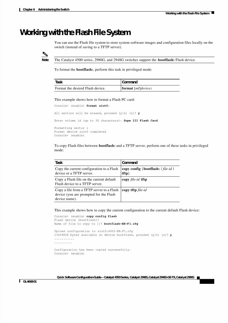
Working with the Flash File SystemYou can use the Flash file system to store system-software images and configuration files locally on the
switch (instead of saving to a TFTP server).
Note The Catalyst 4500 series, 2980G, and 2948G switches support the bootflash: Flash device.
To format the bootflash:, perform this task in privileged mode:
This example shows how to format a Flash PC card:
Console> (enable) format slot0:
All sectors will be erased, proceed (y/n) [n]? y
Enter volume id (up to 30 characters): Supe III Flash Card
Formatting sector 1
Format device slot0 completed
Console> (enable)
To copy Flash files between bootflash: and a TFTP server, perform one of these tasks in privileged
mode:
This example shows how to copy the current configuration to the current default Flash device:
Console> (enable) copy config flash
Flash device [bootflash]?
Name of file to copy to []? bootflash-ER-F1.cfg
Upload configuration to slot0:4003-ER-F1.cfg
13259828 bytes available on device bootflash, proceed (y/n) [n]? y
...........
..........
Configuration has been copied successfully.
Console> (enable)
Task Command
Format the desired Flash device. format [m / ]device:
Task Command
Copy the current configuration to a Flashdevice or a TFTP server.
copy config {bootflash: | file-id |tftp}
Copy a Flash file on the current default
Flash device to a TFTP server.
copy file-id tftp
Copy a file from a TFTP server to a Flash
device (you are prompted for the Flash
device name).
copy tftp file-id
7/23/2019 Sw 4000 Config
http://slidepdf.com/reader/full/sw-4000-config 34/52
4-8
Quick Software Configuration Guide—Catalyst 4500 Series, Catalyst 2948G, Catalyst 2948G-GE-TX, Catalyst 2980G
OL-4668-01
Chapter4 Administering the Switch
Working with the Flash File System
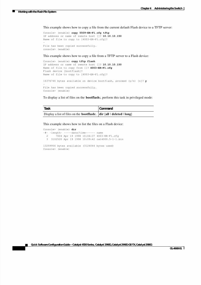
This example shows how to copy a file from the current default Flash device to a TFTP server:
Console> (enable) copy 5509-ER-F1.cfg tftp
IP address or name of remote host []? 10.10.10.150
Name of file to copy to [4003-ER-F1.cfg]?
-
File has been copied successfully.
console> (enable)
This example shows how to copy a file from a TFTP server to a Flash device:
Console> (enable) copy tftp flash
IP address or name of remote host []? 10.10.10.150
Name of file to copy from []? 4003-ER-F1.cfg
Flash device [bootflash]?
Name of file to copy to [4003-ER-F1.cfg]?
16376740 bytes available on device bootflash, proceed (y/n) [n]? y
-
File has been copied successfully.
Console> (enable)
To display a list of files on the bootflash:, perform this task in privileged mode:
This example shows how to list the files on a Flash device:
Console> (enable) dir
-#- -length- -----date/time------ name
2 7004 Apr 19 1998 10:06:37 4003-ER-F1.cfg
3 3102520 Apr 19 1998 10:09:42 cat4000.5-1-1.bin
13259956 bytes available (3124044 bytes used)
Console> (enable)
Task Command
Display a list of files on the bootflash:. dir [all | deleted | long]
7/23/2019 Sw 4000 Config
http://slidepdf.com/reader/full/sw-4000-config 35/52
C H A P T E R
5-1
Quick Software Configuration Guide—Catalyst 4500 Series, Catalyst 2948G, Catalyst 2948G-GE-TX, Catalyst 2980G
OL-4668-01
5
Monitoring the Switch
These sections describe how to monitor the switch using a variety of commands:
• Checking System Status—Display global system status information for the switch.
• Checking Module Status—Display module-specific status information.
• Checking Port Status—Display port-specific status information.
• Checking Port Capabilities—Display feature support information for switch ports.
• Checking Network Connectivity—Test connectivity to other devices using ping and traceroute.
• Displaying Spanning Tree Information—Display the spanning tree state and other information for
ports and VLANs.
• Displaying Neighbor Information—Display information about directly connected Cisco devices.
• Displaying the Forwarding Table—Display the contents of the Layer 2 forwarding table.
• Displaying User Sessions—Display information about active user sessions on the switch.
• Displaying Version Information—Display hardware, firmware, and software version information.
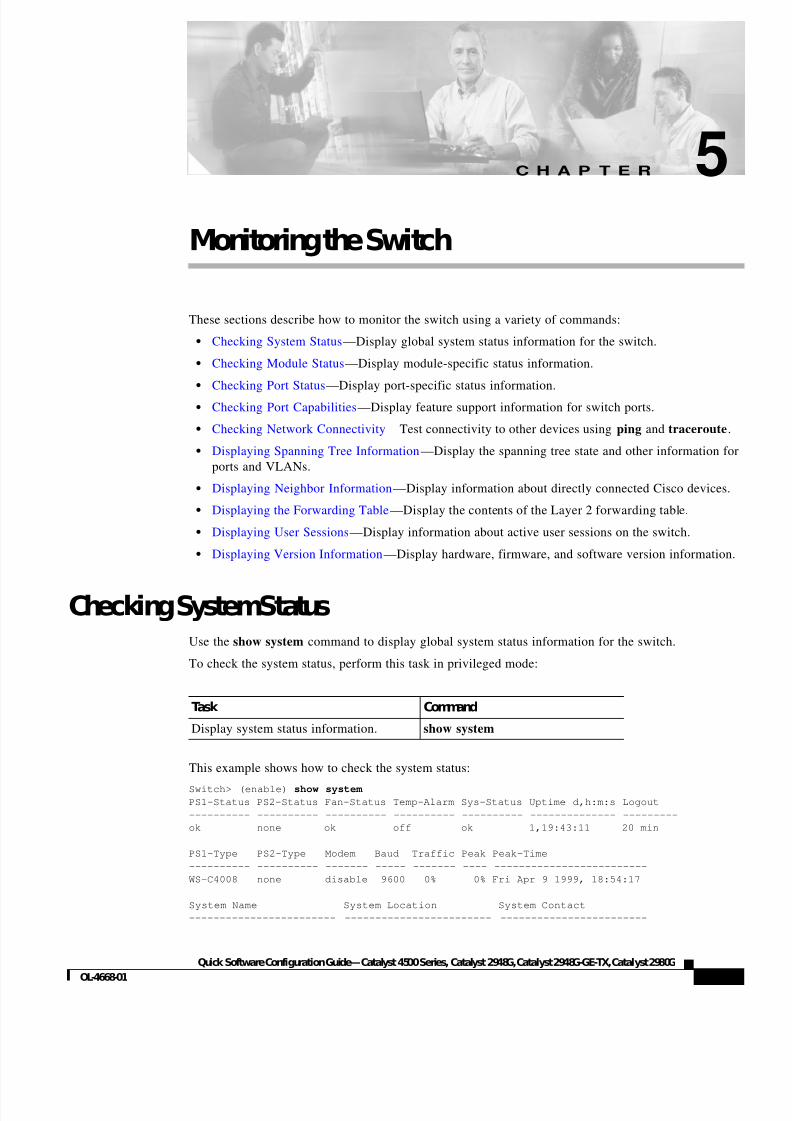
Checking SystemStatusUse the show system command to display global system status information for the switch.
To check the system status, perform this task in privileged mode:
This example shows how to check the system status:
Switch> (enable) show system
PS1-Status PS2-Status Fan-Status Temp-Alarm Sys-Status Uptime d,h:m:s Logout
---------- ---------- ---------- ---------- ---------- -------------- ---------
ok none ok off ok 1,19:43:11 20 min
PS1-Type PS2-Type Modem Baud Traffic Peak Peak-Time
---------- ---------- ------- ----- ------- ---- -------------------------
WS-C4008 none disable 9600 0% 0% Fri Apr 9 1999, 18:54:17
System Name System Location System Contact
------------------------ ------------------------ ------------------------
Task Command
Display system status information. show system
7/23/2019 Sw 4000 Config
http://slidepdf.com/reader/full/sw-4000-config 36/52
5-2
Quick Software Configuration Guide—Catalyst 4500 Series, Catalyst 2948G, Catalyst 2948G-GE-TX, Catalyst 2980G
OL-4668-01
Chapter5 Monitoring the Switch
Checking Module Status
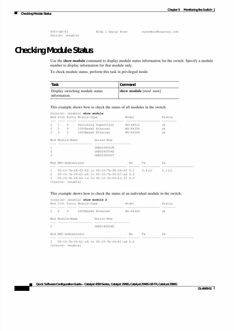
4003-ER-F1 Bldg 1 Equip Room [email protected]
Switch> (enable)
Checking Module StatusUse the show module command to display module status information for the switch. Specify a module
number to display information for that module only.
To check module status, perform this task in privileged mode:
This example shows how to check the status of all modules in the switch:
Console> (enable) show module
Mod Slot Ports Module-Type Model Status
--- ---- ----- ------------------------- ------------------- --------
1 1 0 Switching Supervisor WS-X4012 ok
2 2 6 1000BaseX Ethernet WS-X4306 ok
3 3 6 1000BaseX Ethernet WS-X4306 ok
Mod Module-Name Serial-Num
--- ------------------- --------------------
1 JAB023806JR
2 JAB0240004D
3 JAB024000YY
Mod MAC-Address(es) Hw Fw Sw
--- -------------------------------------- ------ ---------- -----------------
1 00-10-7b-f8-03-00 to 00-10-7b-f8-06-ff 0.1 4.4(1) 5.1(1)
2 00-10-7b-f6-b1-a8 to 00-10-7b-f6-b1-ad 0.23 00-10-7b-f6-b2-1a to 00-10-7b-f6-b2-1f 0.2
Console> (enable)
This example shows how to check the status of an individual module in the switch:
Console> (enable) show module 2
Mod Slot Ports Module-Type Model Status
--- ---- ----- ------------------------- ------------------- --------
2 2 6 1000BaseX Ethernet WS-X4306 ok
Mod Module-Name Serial-Num
--- ------------------- --------------------
2 JAB0240004D
Mod MAC-Address(es) Hw Fw Sw
--- -------------------------------------- ------ ---------- -----------------
2 00-10-7b-f6-b1-a8 to 00-10-7b-f6-b1-ad 0.2
Console> (enable)
Task Command
Display switching module status
information.
show module [mod_num]
7/23/2019 Sw 4000 Config
http://slidepdf.com/reader/full/sw-4000-config 37/52
5-3
Quick Software Configuration Guide—Catalyst 4500 Series, Catalyst 2948G, Catalyst 2948G-GE-TX, Catalyst 2980G
OL-4668-01
Chapter5 Monitoring the Switch
Checking Port Status
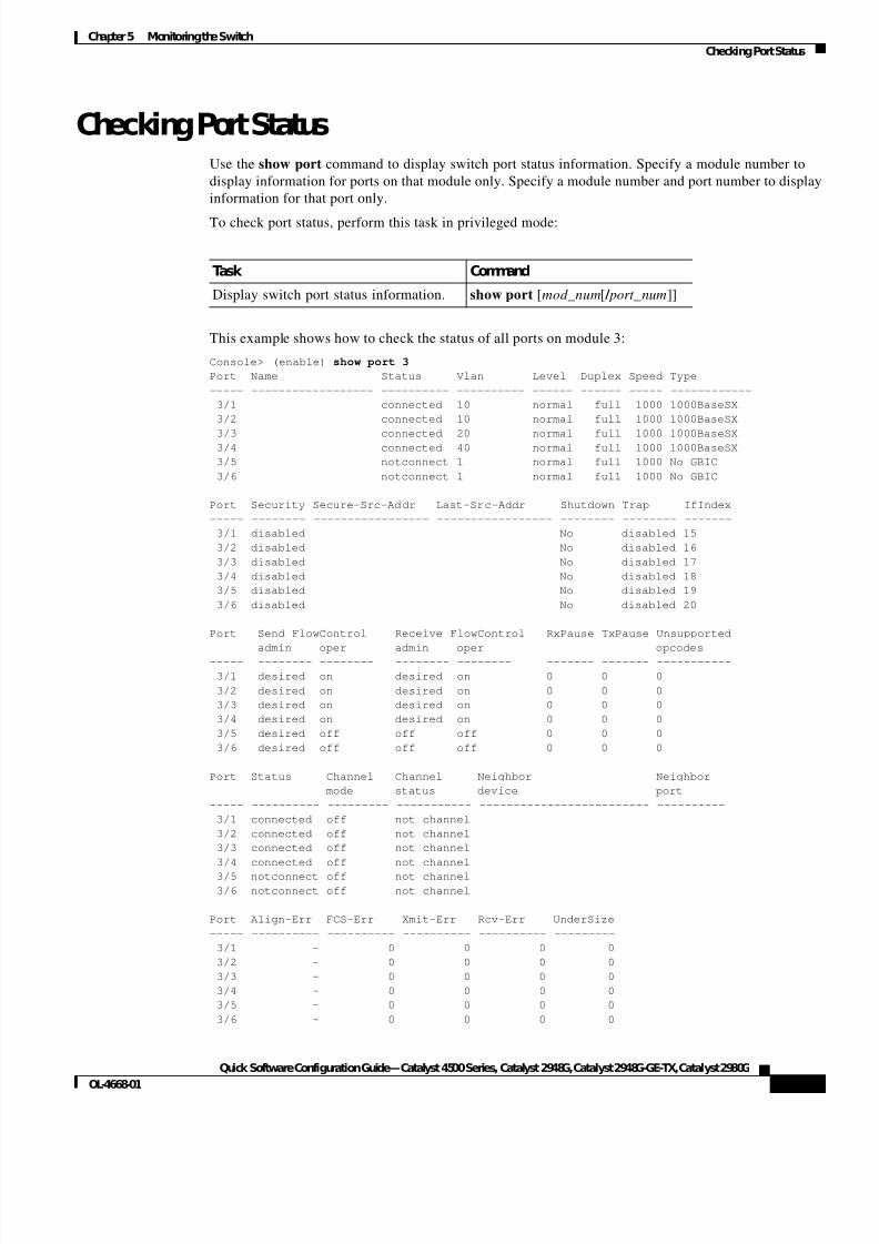
Checking Port StatusUse the show port command to display switch port status information. Specify a module number to
display information for ports on that module only. Specify a module number and port number to display
information for that port only.
To check port status, perform this task in privileged mode:
This example shows how to check the status of all ports on module 3:
Console> (enable) show port 3
Port Name Status Vlan Level Duplex Speed Type
----- ------------------ ---------- ---------- ------ ------ ----- ------------
3/1 connected 10 normal full 1000 1000BaseSX
3/2 connected 10 normal full 1000 1000BaseSX
3/3 connected 20 normal full 1000 1000BaseSX 3/4 connected 40 normal full 1000 1000BaseSX
3/5 notconnect 1 normal full 1000 No GBIC
3/6 notconnect 1 normal full 1000 No GBIC
Port Security Secure-Src-Addr Last-Src-Addr Shutdown Trap IfIndex
----- -------- ----------------- ----------------- -------- -------- -------
3/1 disabled No disabled 15
3/2 disabled No disabled 16
3/3 disabled No disabled 17
3/4 disabled No disabled 18
3/5 disabled No disabled 19
3/6 disabled No disabled 20
Port Send FlowControl Receive FlowControl RxPause TxPause Unsupported
admin oper admin oper opcodes
----- -------- -------- -------- -------- ------- ------- -----------
3/1 desired on desired on 0 0 0
3/2 desired on desired on 0 0 0
3/3 desired on desired on 0 0 0
3/4 desired on desired on 0 0 0
3/5 desired off off off 0 0 0
3/6 desired off off off 0 0 0
Port Status Channel Channel Neighbor Neighbor
mode status device port
----- ---------- --------- ----------- ------------------------- ----------
3/1 connected off not channel
3/2 connected off not channel
3/3 connected off not channel
3/4 connected off not channel
3/5 notconnect off not channel
3/6 notconnect off not channel
Port Align-Err FCS-Err Xmit-Err Rcv-Err UnderSize
----- ---------- ---------- ---------- ---------- ---------
3/1 - 0 0 0 0
3/2 - 0 0 0 0
3/3 - 0 0 0 0
3/4 - 0 0 0 0
3/5 - 0 0 0 0
3/6 - 0 0 0 0
Task Command
Display switch port status information. show port [mod_num[ / port_num]]
7/23/2019 Sw 4000 Config
http://slidepdf.com/reader/full/sw-4000-config 38/52
5-4
Quick Software Configuration Guide—Catalyst 4500 Series, Catalyst 2948G, Catalyst 2948G-GE-TX, Catalyst 2980G
OL-4668-01
Chapter5 Monitoring the Switch
Checking Port Capabilities
Port Single-Col Multi-Coll Late-Coll Excess-Col Carri-Sen Runts Giants
----- ---------- ---------- ---------- ---------- --------- --------- ---------
3/1 0 0 0 0 0 0 0
3/2 0 0 0 0 0 0 0
3/3 0 0 0 0 0 0 0
3/4 0 0 0 0 0 0 0
3/5 0 0 0 0 0 0 0 3/6 0 0 0 0 0 0 0
Last-Time-Cleared
--------------------------
Fri Apr 30 1999, 18:54:17
Console> (enable)
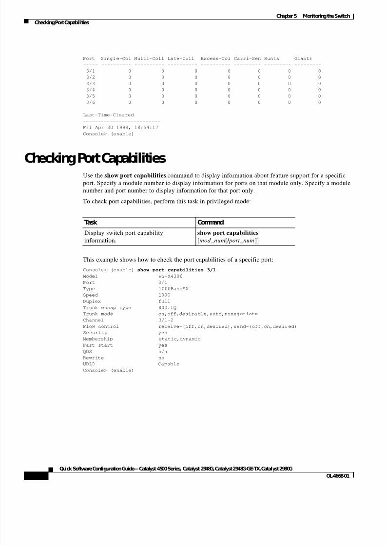
Checking Port CapabilitiesUse the show port capabilities command to display information about feature support for a specific
port. Specify a module number to display information for ports on that module only. Specify a module
number and port number to display information for that port only.
To check port capabilities, perform this task in privileged mode:
This example shows how to check the port capabilities of a specific port:
Console> (enable) show port capabilities 3/1
Model WS-X4306
Port 3/1
Type 1000BaseSX
Speed 1000
Duplex full
Trunk encap type 802.1Q
Trunk mode on,off,desirable,auto,nonegotiate
Channel 3/1-2
Flow control receive-(off,on,desired),send-(off,on,desired)
Security yes
Membership static,dynamic
Fast start yes
QOS n/a
Rewrite no
UDLD Capable
Console> (enable)
Task Command
Display switch port capability
information.
show port capabilities
[mod_num[ / port_num]]
7/23/2019 Sw 4000 Config
http://slidepdf.com/reader/full/sw-4000-config 39/52
5-5
Quick Software Configuration Guide—Catalyst 4500 Series, Catalyst 2948G, Catalyst 2948G-GE-TX, Catalyst 2980G
OL-4668-01
Chapter5 Monitoring the Switch
Checking Network Connectivity
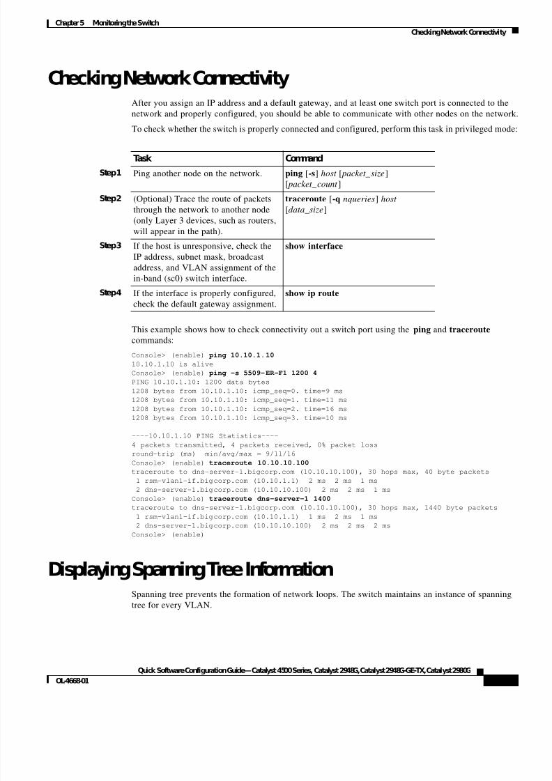
Checking Network ConnectivityAfter you assign an IP address and a default gateway, and at least one switch port is connected to the
network and properly configured, you should be able to communicate with other nodes on the network
To check whether the switch is properly connected and configured, perform this task in privileged mode
This example shows how to check connectivity out a switch port using the ping and traceroute
commands:
Console> (enable) ping 10.10.1.10
10.10.1.10 is alive
Console> (enable) ping -s 5509-ER-F1 1200 4
PING 10.10.1.10: 1200 data bytes
1208 bytes from 10.10.1.10: icmp_seq=0. time=9 ms
1208 bytes from 10.10.1.10: icmp_seq=1. time=11 ms
1208 bytes from 10.10.1.10: icmp_seq=2. time=16 ms1208 bytes from 10.10.1.10: icmp_seq=3. time=10 ms
----10.10.1.10 PING Statistics----
4 packets transmitted, 4 packets received, 0% packet loss
round-trip (ms) min/avg/max = 9/11/16
Console> (enable) traceroute 10.10.10.100
traceroute to dns-server-1.bigcorp.com (10.10.10.100), 30 hops max, 40 byte packets
1 rsm-vlan1-if.bigcorp.com (10.10.1.1) 2 ms 2 ms 1 ms
2 dns-server-1.bigcorp.com (10.10.10.100) 2 ms 2 ms 1 ms
Console> (enable) traceroute dns-server-1 1400
traceroute to dns-server-1.bigcorp.com (10.10.10.100), 30 hops max, 1440 byte packets
1 rsm-vlan1-if.bigcorp.com (10.10.1.1) 1 ms 2 ms 1 ms
2 dns-server-1.bigcorp.com (10.10.10.100) 2 ms 2 ms 2 ms
Console> (enable)
Displaying Spanning Tree InformationSpanning tree prevents the formation of network loops. The switch maintains an instance of spanning
tree for every VLAN.
Task Command
Step1 Ping another node on the network. ping [-s] host [ packet_size]
[ packet_count ]
Step2 (Optional) Trace the route of packets
through the network to another node
(only Layer 3 devices, such as routers,
will appear in the path).
traceroute [-q nqueries] host
[data_size]
Step3 If the host is unresponsive, check the
IP address, subnet mask, broadcast
address, and VLAN assignment of the
in-band (sc0) switch interface.
show interface
Step4 If the interface is properly configured,
check the default gateway assignment.
show ip route
7/23/2019 Sw 4000 Config
http://slidepdf.com/reader/full/sw-4000-config 40/52
5-6
Quick Software Configuration Guide—Catalyst 4500 Series, Catalyst 2948G, Catalyst 2948G-GE-TX, Catalyst 2980G
OL-4668-01
Chapter5 Monitoring the Switch
Displaying Neighbor Information
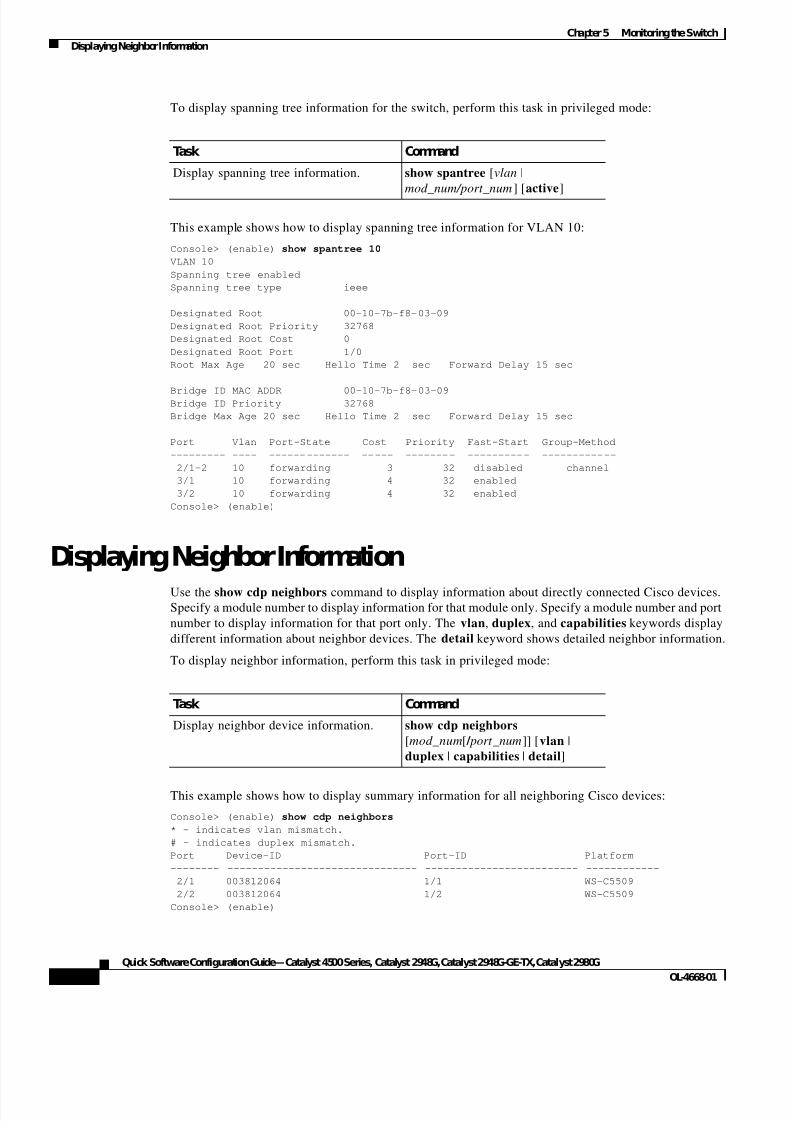
To display spanning tree information for the switch, perform this task in privileged mode:
This example shows how to display spanning tree information for VLAN 10:
Console> (enable) show spantree 10
VLAN 10
Spanning tree enabled
Spanning tree type ieee
Designated Root 00-10-7b-f8-03-09
Designated Root Priority 32768
Designated Root Cost 0
Designated Root Port 1/0
Root Max Age 20 sec Hello Time 2 sec Forward Delay 15 sec
Bridge ID MAC ADDR 00-10-7b-f8-03-09Bridge ID Priority 32768
Bridge Max Age 20 sec Hello Time 2 sec Forward Delay 15 sec
Port Vlan Port-State Cost Priority Fast-Start Group-Method
--------- ---- ------------- ----- -------- ---------- ------------
2/1-2 10 forwarding 3 32 disabled channel
3/1 10 forwarding 4 32 enabled
3/2 10 forwarding 4 32 enabled
Console> (enable)
Displaying Neighbor InformationUse the show cdp neighbors command to display information about directly connected Cisco devices.Specify a module number to display information for that module only. Specify a module number and port
number to display information for that port only. The vlan, duplex, and capabilities keywords display
different information about neighbor devices. The detail keyword shows detailed neighbor information.
To display neighbor information, perform this task in privileged mode:
This example shows how to display summary information for all neighboring Cisco devices:
Console> (enable) show cdp neighbors
* - indicates vlan mismatch.
# - indicates duplex mismatch.
Port Device-ID Port-ID Platform
-------- ------------------------------- ------------------------- ------------
2/1 003812064 1/1 WS-C5509
2/2 003812064 1/2 WS-C5509
Console> (enable)
Task Command
Display spanning tree information. show spantree [vlan |
mod_num/port_num] [active]
Task Command
Display neighbor device information. show cdp neighbors
[mod_num[ / port_num]] [vlan |
duplex | capabilities | detail]
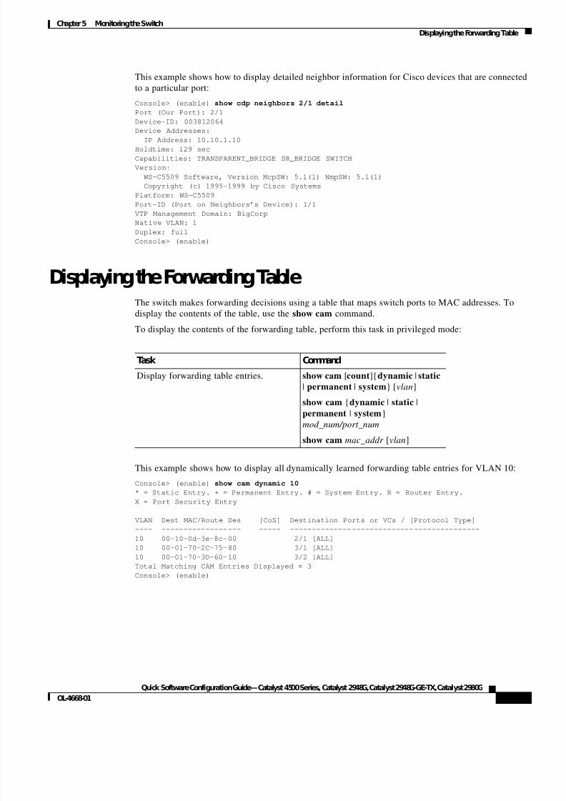
7/23/2019 Sw 4000 Config
http://slidepdf.com/reader/full/sw-4000-config 41/52
5-7
Quick Software Configuration Guide—Catalyst 4500 Series, Catalyst 2948G, Catalyst 2948G-GE-TX, Catalyst 2980G
OL-4668-01
Chapter5 Monitoring the Switch
Displaying the Forwarding Table
This example shows how to display detailed neighbor information for Cisco devices that are connected
to a particular port:
Console> (enable) show cdp neighbors 2/1 detail
Port (Our Port): 2/1
Device-ID: 003812064
Device Addresses:
IP Address: 10.10.1.10Holdtime: 129 sec
Capabilities: TRANSPARENT_BRIDGE SR_BRIDGE SWITCH
Version:
WS-C5509 Software, Version McpSW: 5.1(1) NmpSW: 5.1(1)
Copyright (c) 1995-1999 by Cisco Systems
Platform: WS-C5509
Port-ID (Port on Neighbors’s Device): 1/1
VTP Management Domain: BigCorp
Native VLAN: 1
Duplex: full
Console> (enable)
Displaying the Forwarding TableThe switch makes forwarding decisions using a table that maps switch ports to MAC addresses. To
display the contents of the table, use the show cam command.
To display the contents of the forwarding table, perform this task in privileged mode:
This example shows how to display all dynamically learned forwarding table entries for VLAN 10:
Console> (enable) show cam dynamic 10
* = Static Entry. + = Permanent Entry. # = System Entry. R = Router Entry.
X = Port Security Entry
VLAN Dest MAC/Route Des [CoS] Destination Ports or VCs / [Protocol Type]
---- ------------------ ----- -------------------------------------------
10 00-10-0d-3e-8c-00 2/1 [ALL]
10 00-01-70-2C-75-80 3/1 [ALL]
10 00-01-70-3D-60-10 3/2 [ALL]
Total Matching CAM Entries Displayed = 3
Console> (enable)
Task Command
Display forwarding table entries. show cam [count]{dynamic | static
| permanent | system} [vlan]
show cam {dynamic | static |
permanent | system}
mod_num/port_num
show cam mac_addr [vlan]
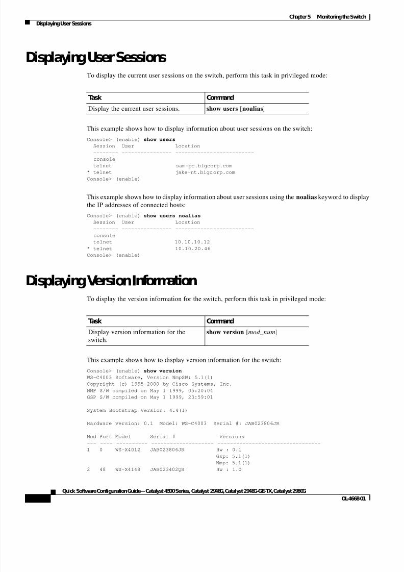
7/23/2019 Sw 4000 Config
http://slidepdf.com/reader/full/sw-4000-config 42/52
5-8
Quick Software Configuration Guide—Catalyst 4500 Series, Catalyst 2948G, Catalyst 2948G-GE-TX, Catalyst 2980G
OL-4668-01
Chapter5 Monitoring the Switch
Displaying User Sessions
Displaying User SessionsTo display the current user sessions on the switch, perform this task in privileged mode:
This example shows how to display information about user sessions on the switch:
Console> (enable) show users
Session User Location
-------- ---------------- -------------------------
console
telnet sam-pc.bigcorp.com
* telnet jake-nt.bigcorp.com
Console> (enable)
This example shows how to display information about user sessions using thenoalias
keyword to displaythe IP addresses of connected hosts:
Console> (enable) show users noalias
Session User Location
-------- ---------------- -------------------------
console
telnet 10.10.10.12
* telnet 10.10.20.46
Console> (enable)
Displaying Version Information
To display the version information for the switch, perform this task in privileged mode:
This example shows how to display version information for the switch:
Console> (enable) show version
WS-C4003 Software, Version NmpSW: 5.1(1)
Copyright (c) 1995-2000 by Cisco Systems, Inc.
NMP S/W compiled on May 1 1999, 05:20:04
GSP S/W compiled on May 1 1999, 23:59:01
System Bootstrap Version: 4.4(1)
Hardware Version: 0.1 Model: WS-C4003 Serial #: JAB023806JR
Mod Port Model Serial # Versions
--- ---- ---------- -------------------- ---------------------------------
1 0 WS-X4012 JAB023806JR Hw : 0.1
Gsp: 5.1(1)
Nmp: 5.1(1)
2 48 WS-X4148 JAB023402QH Hw : 1.0
Task CommandDisplay the current user sessions. show users [noalias]
Task Command
Display version information for the
switch.
show version [mod_num]
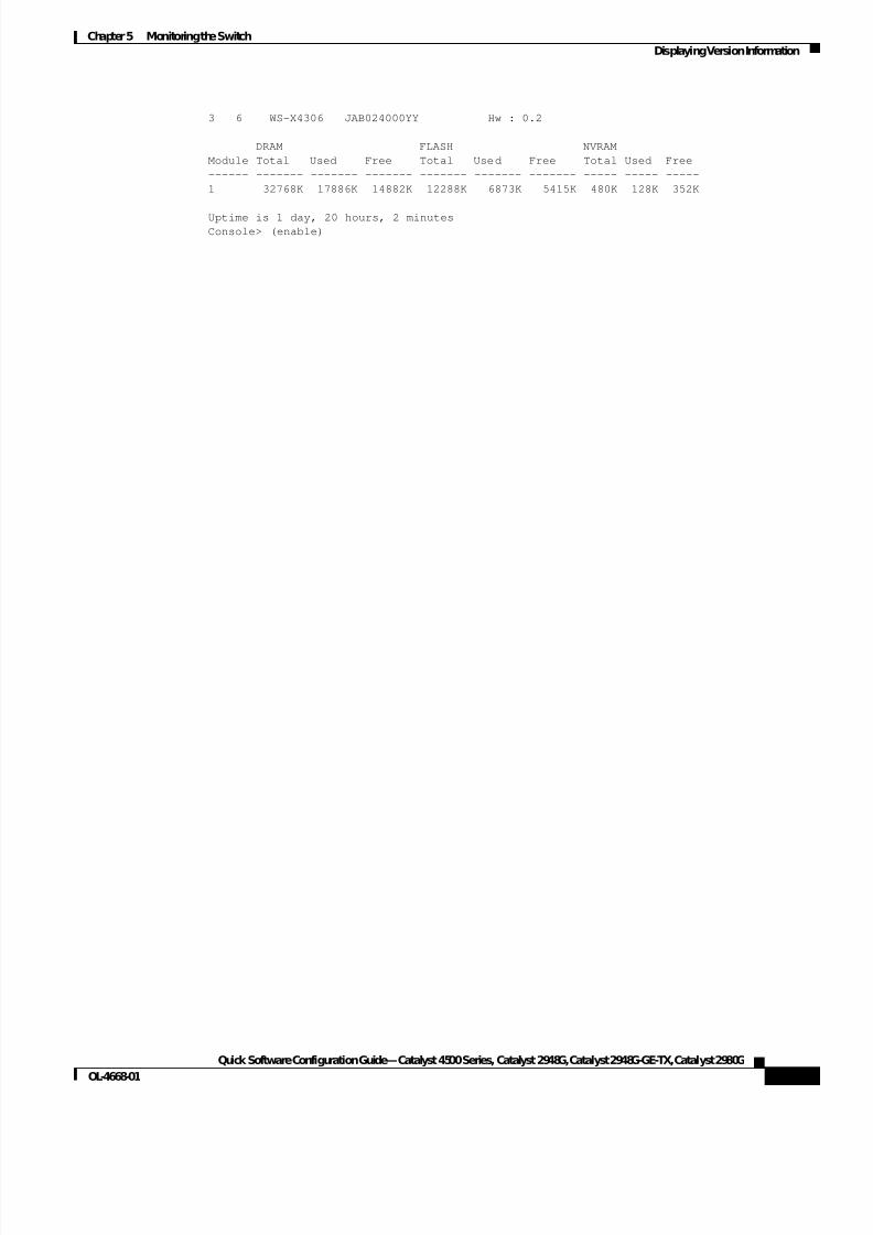
7/23/2019 Sw 4000 Config
http://slidepdf.com/reader/full/sw-4000-config 43/52
5-9
Quick Software Configuration Guide—Catalyst 4500 Series, Catalyst 2948G, Catalyst 2948G-GE-TX, Catalyst 2980G
OL-4668-01
Chapter5 Monitoring the Switch
Displaying Version Information
3 6 WS-X4306 JAB024000YY Hw : 0.2
DRAM FLASH NVRAM
Module Total Used Free Total Used Free Total Used Free
------ ------- ------- ------- ------- ------- ------- ----- ----- -----
1 32768K 17886K 14882K 12288K 6873K 5415K 480K 128K 352K
Uptime is 1 day, 20 hours, 2 minutesConsole> (enable)

7/23/2019 Sw 4000 Config
http://slidepdf.com/reader/full/sw-4000-config 44/52
5-10
Quick Software Configuration Guide—Catalyst 4500 Series, Catalyst 2948G, Catalyst 2948G-GE-TX, Catalyst 2980G
OL-4668-01
Chapter5 Monitoring the Switch
Displaying Version Information
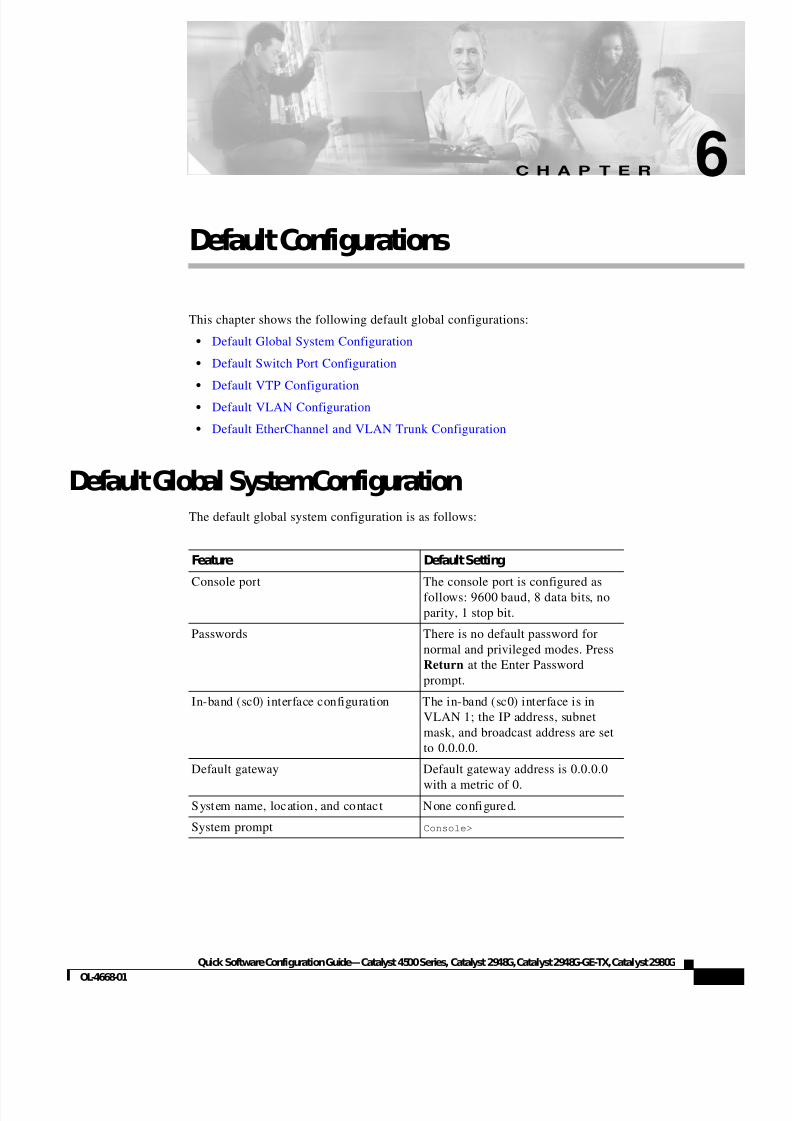
7/23/2019 Sw 4000 Config
http://slidepdf.com/reader/full/sw-4000-config 45/52
C H A P T E R
6-1
Quick Software Configuration Guide—Catalyst 4500 Series, Catalyst 2948G, Catalyst 2948G-GE-TX, Catalyst 2980G
OL-4668-01
6
Default Configurations
This chapter shows the following default global configurations:
• Default Global System Configuration
• Default Switch Port Configuration
• Default VTP Configuration
• Default VLAN Configuration
• Default EtherChannel and VLAN Trunk Configuration
Default Global SystemConfigurationThe default global system configuration is as follows:
Feature Default Setting
Console port The console port is configured as
follows: 9600 baud, 8 data bits, no
parity, 1 stop bit.
Passwords There is no default password for
normal and privileged modes. Press
Return at the Enter Password
prompt.
In-band (sc0) interface configuration The in-band (sc0) interface is in
VLAN 1; the IP address, subnet
mask, and broadcast address are set
to 0.0.0.0.
Default gateway Default gateway address is 0.0.0.0
with a metric of 0.
System name, location, and contact None configured.
System prompt Console>
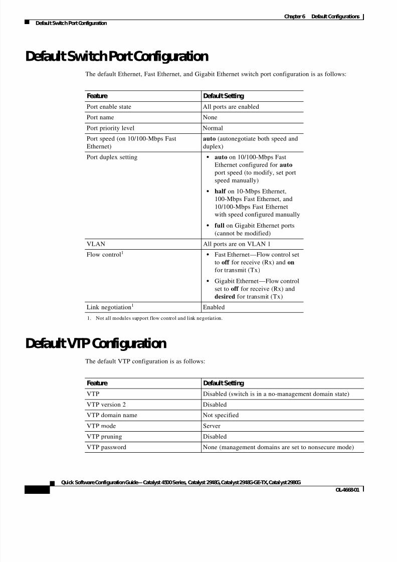
7/23/2019 Sw 4000 Config
http://slidepdf.com/reader/full/sw-4000-config 46/52
6-2
Quick Software Configuration Guide—Catalyst 4500 Series, Catalyst 2948G, Catalyst 2948G-GE-TX, Catalyst 2980G
OL-4668-01
Chapter6 Default Configurations
Default Switch Port Configuration
Default Switch Port ConfigurationThe default Ethernet, Fast Ethernet, and Gigabit Ethernet switch port configuration is as follows:
Default VTP ConfigurationThe default VTP configuration is as follows:
Feature Default SettingPort enable state All ports are enabled
Port name None
Port priority level Normal
Port speed (on 10/100-Mbps Fast
Ethernet)
auto (autonegotiate both speed and
duplex)
Port duplex setting • auto on 10/100-Mbps Fast
Ethernet configured for auto
port speed (to modify, set port
speed manually)
• half on 10-Mbps Ethernet,
100-Mbps Fast Ethernet, and
10/100-Mbps Fast Ethernet
with speed configured manually
• full on Gigabit Ethernet ports
(cannot be modified)
VLAN All ports are on VLAN 1
Flow control1
1. Not all modules support flow control and link negotiation.
• Fast Ethernet—Flow control set
to off for receive (Rx) and on
for transmit (Tx)
• Gigabit Ethernet—Flow control
set to off for receive (Rx) and
desired for transmit (Tx)
Link negotiation1 Enabled
Feature Default Setting
VTP Disabled (switch is in a no-management domain state)
VTP version 2 Disabled
VTP domain name Not specified
VTP mode Server
VTP pruning Disabled
VTP password None (management domains are set to nonsecure mode)
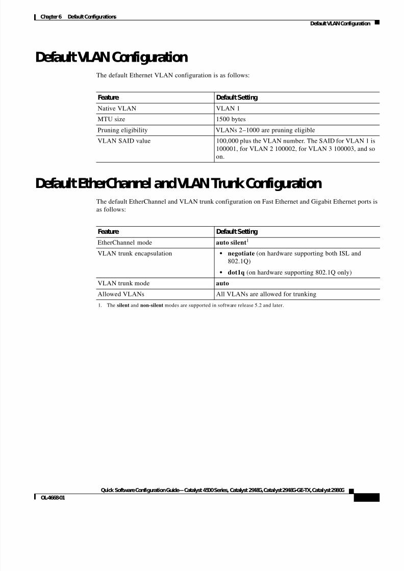
7/23/2019 Sw 4000 Config
http://slidepdf.com/reader/full/sw-4000-config 47/52
6-3
Quick Software Configuration Guide—Catalyst 4500 Series, Catalyst 2948G, Catalyst 2948G-GE-TX, Catalyst 2980G
OL-4668-01
Chapter6 Default Configurations
Default VLAN Configuration
Default VLAN ConfigurationThe default Ethernet VLAN configuration is as follows:
Default EtherChannel and VLAN Trunk ConfigurationThe default EtherChannel and VLAN trunk configuration on Fast Ethernet and Gigabit Ethernet ports isas follows:
Feature Default SettingNative VLAN VLAN 1
MTU size 1500 bytes
Pruning eligibility VLANs 2–1000 are pruning eligible
VLAN SAID value 100,000 plus the VLAN number. The SAID for VLAN 1 is
100001, for VLAN 2 100002, for VLAN 3 100003, and so
on.
Feature Default Setting
EtherChannel mode auto silent1
1. The silent and non-silent modes are supported in software release 5.2 and later.
VLAN trunk encapsulation • negotiate (on hardware supporting both ISL and
802.1Q)
• dot1q (on hardware supporting 802.1Q only)
VLAN trunk mode auto
Allowed VLANs All VLANs are allowed for trunking

7/23/2019 Sw 4000 Config
http://slidepdf.com/reader/full/sw-4000-config 48/52
6-4
Quick Software Configuration Guide—Catalyst 4500 Series, Catalyst 2948G, Catalyst 2948G-GE-TX, Catalyst 2980G
OL-4668-01
Chapter6 Default Configurations
Default EtherChannel and VLAN Trunk Configuration
7/23/2019 Sw 4000 Config
http://slidepdf.com/reader/full/sw-4000-config 49/52
IN-1
Quick Software Configuration Guide—Catalyst 4500 Series, Catalyst 2948G, Catalyst 2948G-GE-TX, Catalyst 2980G
OL-4668-01
I N D E X
A
assigning switch ports to VLANs 2-5
auto mode 3-1
B
banner, login 4-2booting the switch
BOOTP and RARP 1-2
procedure 1-2
BOOTP 1-2
C
CAM table, displaying 5-7
capabilities, checking on port 5-4
checking status
modules 5-2
ports 5-3
system 5-1
configuration files
configuring switch from TFTP server 4-5
copying to TFTP server 4-4
displaying current configuration 4-4
connectivity, checking 5-5
console port
connecting to 1-1
default configuration 6-1
viewing sessions 5-8
conventions, document vi
copy config command 4-7
copy config tftp command 4-4,4-5
copy tftp flash command 4-5
creating VLANs 2-4
D
default Flash device 4-7
default gateway
configuring 1-3default configuration 6-1
defaults
EtherChannel 6-3
global system settings 6-1
switch ports 6-2
trunks 6-3
VLANs 6-3
VTP 6-2
desirable mode 3-1
dir command 4-8
DNS, configuring 4-3
documentation
obtaining vii
documentation, related vi
document conventions vi
duplex 1-4,6-2
E
enable command 1-2
encapsulation
IEEE 802.1Q 3-2
ISL 3-2
7/23/2019 Sw 4000 Config
http://slidepdf.com/reader/full/sw-4000-config 50/52
Index
IN-2
Quick Software Configuration Guide—Catalyst 4500 Series, Catalyst 2948G, Catalyst 2948G-GE-TX, Catalyst 2980G
OL-4668-01
EtherChannel
configuring 3-2
default configuration 6-3
Ethernet ports
configuring 1-4
default configuration 6-2
F
Fast Ethernet ports
configuring 1-4
default configuration 6-2
default trunk configuration 6-3
Flash file system
copying files 4-7
default device, setting 4-7
listing files 4-8
flow control 1-4
format command 4-7
formatting Flash PC cards 4-7
forwarding table, displaying 5-7
G
Gigabit Ethernet ports
configuring 1-4
default configuration 6-2
default trunk configuration 6-3
global system settings
configuring 4-1
default 6-1
H
host names 4-3
I
IEEE 802.1Q 3-2
in-band (sc0) interface
default configuration 6-1
setting IP address 1-3
Inter-Switch Link
See ISL
IP address
BOOTP and RARP 1-2
default configuration 6-1
setting 1-3
ISL 3-2
L
link negotiation 1-4
listing Flash files 4-8
login banner 4-2
M
me1 interface 1-3
message of the day 4-2
module
checking status 5-2
N
negotiation, link 1-4
neighbor information, displaying 5-6
network connectivity, checking 5-5
O
out-of-band management Ethernet (me1) interface 1-3
7/23/2019 Sw 4000 Config
http://slidepdf.com/reader/full/sw-4000-config 51/52
Index
IN-3
Quick Software Configuration Guide—Catalyst 4500 Series, Catalyst 2948G, Catalyst 2948G-GE-TX, Catalyst 2980G
OL-4668-01
P
PAgP 3-1
passwords
default configuration 6-1
setting 4-2
PCMCIA cards
See Flash PC cards
ping command 5-5
Port Aggregation Protocol
See PAgP
port duplex 1-4,6-2
port priority 6-2
ports
assigning to VLANs 2-5
checking capabilities 5-4
checking status 5-3
default configuration 6-2
port speed 1-4,6-2
preparing to configure 1-1
privileged mode, entering 1-2
R
RARP 1-2
related documentation vi
S
sc0 interface
See in-band (sc0) interface
sessions, viewing 5-8set banner motd command 4-2
set boot system flash command 4-5
set enablepass command 4-2
set interface sc0 command 1-3
set ip dns domain command 4-3
set ip dns enable command 4-3
set ip dns server command 4-3
set ip route default command 1-3
set module name command 4-1
set password command 4-2
set port channel command 3-2
set port duplex command 1-4
set port flowcontrol command 1-4
set port name command 1-4
set port speed command 1-4
set prompt command 4-1
set system contact command 4-1
set system location command 4-1
set system name command 4-1
set time command 4-1
set trunk command 3-3
set vlan command 2-4,2-5
set vtp domain command 2-2
set vtp mode client command 2-2
set vtp mode server command 2-2
set vtp mode transparent command 2-3
show cam command 5-7
show cdp neighbors command 5-6
show config command 4-4
show interface command 5-5show ip dns command 4-3
show ip route command 5-5
show module command 5-2
show port capabilities command 5-4
show port channel command 3-2
show port command 1-4,2-5,5-3
show system command 5-1
show trunk command 3-3
show users command 5-8
show version command 5-8
show vlan command 2-4,2-5
show vtp domain command 2-2
software images
copying from TFTP server 4-5
spanning tree information, displaying 5-5
speed 1-4,6-2
7/23/2019 Sw 4000 Config
http://slidepdf.com/reader/full/sw-4000-config 52/52
Index
switch
preparing to configure 1-1
switch ports
assigning to VLANs 2-5
default configuration 6-2
system settings
configuring 4-1
default 6-1
system status, checking 5-1
T
Telnet sessions, viewing 5-8
terminal configuration 1-2
TFTP server
configuring switch from 4-5
copying configuration to 4-4
copying software images from 4-5
traceroute command 5-5
trunks
configuring 3-2
default configuration 6-3
U
user sessions, viewing 5-8
V
version information, displaying 5-8
VLAN
assigning switch ports to 2-5creating 2-4
default configuration 6-3
in-band (sc0) interface assignment 1-3
trunks
configuring 3-2
default configuration 6-3
VLAN Trunk Protocol
See VTP
VTP
client 2-1,2-2
default configuration 6-2
overview 2-1
server 2-1,2-2
transparent 2-1,2-3