Reduced graphene oxide–bismuth oxide composite as electrode material for supercapacitors
7
ORIGINAL PAPER Reduced graphene oxide–bismuth oxide composite as electrode material for supercapacitors Mateusz Ciszewski & Andrzej Mianowski & Piotr Szatkowski & Ginter Nawrat & Jakub Adamek Received: 24 February 2014 /Revised: 25 May 2014 /Accepted: 9 June 2014 # The Author(s) 2014. This article is published with open access at Springerlink.com Abstract We have reported a new reduced graphene oxide– bismuth oxide composite that can be used as a supercapacitor electrode. Bi 2 O 3 was synthesized from bismuth nitrate pentahydrate and oxalic acid as a precipitating agent using a hydrothermal process in an aqueous graphene oxide suspen- sion. Instead of mixing graphene oxide with bismuth oxide, we have developed a bismuth oxalate precipitation between the layers. As prepared, composite of hydrated bismuth oxa- late and graphene oxide was converted to bismuth oxide and reduced graphene oxide by thermal decomposition in a muffle stove. The material exhibited the specific capacitance of 94 F/ g at current density 0.2 A/g. Using the cyclic voltammetry, the specific capacitance was as high as 55 F/g at scan rate 5 mV/s over the potential range 0–1 V. The material exhibited long- term cycle stability retaining 90 % specific capacitance after 3,000 cycles. Except Bi 3+ ions present in Bi 2 O 3 , some amount of higher energy Bi 5+ was confirmed. Keywords Graphene oxide . Bismuth oxide . Supercapacitors . Thermal treatment Introduction Electrochemical supercapacitors are the promising energy stor- age materials that due to long cycle life and high-power density may be applied in many areas of everyday living, i.e., back-up memories, traffic warning signals, engine starting and acceler- ation, and load lifting. They briefly store electric energy in an electrochemical double layer, so-called Helmholtz layer, forming the solid-electrolyte interface. As their capacitance is proportional to the surface area of the electrode material, highly porous, chemically and electrochemically inert carbons are considered as good candidates for supercapacitor matrices. The higher specific surface area, the higher charge contact interface; however, an increase in capacitance may be also obtained by intercalation of an active species like conducting polymers, metal nanoparticles, and metal oxides. Composite materials containing metal oxide are generally classified as conversion electrodes [1], where capacitance arises from typical charge separation and pseudocapacitance caused by Faradaic reactions [2]. Redox reactions between electrolyte and metal oxide can significantly increase the specific capacitance. Within many proposals of metal oxide–carbon composites, transition metal oxides are privileged; however, silicon and tin chemistry is also well developed. In this paper, we report a reduced graphene oxide–bismuth oxide composite produced by interca- lation of graphene oxide suspension with bismuth nitrate and subsequent precipitation of bismuth salt using oxalic acid as a precipitating agent. In the second step as prepared, composite is thermally treated to reduce graphene oxide and convert bismuth oxalate into bismuth oxide. Recently, the interest in poor metals and metalloids in energy storage devices is growing up. Among them, bismuth seems to be a good candidate because of non- toxic character in comparison to the neighbors from the periodic table, namely, lead and antimony [3]. Generally, bismuth chem- istry is mainly focused on medical and catalytic applications. In medicine, bismuth compounds are most commonly used for M. Ciszewski (*) : A. Mianowski : G. Nawrat Faculty of Chemistry, Department of Inorganic, Analytical Chemistry and Electrochemistry, Silesian University of Technology, Krzywoustego 6, 44-100 Gliwice, Poland e-mail: [email protected] P. Szatkowski Faculty of Materials Science and Ceramics, Department of Biomaterials, AGH University of Science and Technology, Mickiewicza 30, 30-059 Krakow, Poland J. Adamek Faculty of Chemistry, Department of Organic Chemistry, Biochemistry and Biotechnology, Silesian University of Technology, Krzywoustego 4, 44-100 Gliwice, Poland Ionics DOI 10.1007/s11581-014-1182-4
Transcript of Reduced graphene oxide–bismuth oxide composite as electrode material for supercapacitors
ORIGINAL PAPER
Reduced graphene oxide–bismuth oxide composite as electrodematerial for supercapacitors
Mateusz Ciszewski & Andrzej Mianowski &Piotr Szatkowski & Ginter Nawrat & Jakub Adamek
Received: 24 February 2014 /Revised: 25 May 2014 /Accepted: 9 June 2014# The Author(s) 2014. This article is published with open access at Springerlink.com
Abstract We have reported a new reduced graphene oxide–bismuth oxide composite that can be used as a supercapacitorelectrode. Bi2O3 was synthesized from bismuth nitratepentahydrate and oxalic acid as a precipitating agent using ahydrothermal process in an aqueous graphene oxide suspen-sion. Instead of mixing graphene oxide with bismuth oxide,we have developed a bismuth oxalate precipitation betweenthe layers. As prepared, composite of hydrated bismuth oxa-late and graphene oxide was converted to bismuth oxide andreduced graphene oxide by thermal decomposition in a mufflestove. The material exhibited the specific capacitance of 94 F/g at current density 0.2 A/g. Using the cyclic voltammetry, thespecific capacitance was as high as 55 F/g at scan rate 5 mV/sover the potential range 0–1 V. The material exhibited long-term cycle stability retaining 90 % specific capacitance after3,000 cycles. Except Bi3+ ions present in Bi2O3, some amountof higher energy Bi5+ was confirmed.
Keywords Graphene oxide . Bismuth oxide .
Supercapacitors . Thermal treatment
Introduction
Electrochemical supercapacitors are the promising energy stor-age materials that due to long cycle life and high-power densitymay be applied in many areas of everyday living, i.e., back-upmemories, traffic warning signals, engine starting and acceler-ation, and load lifting. They briefly store electric energy in anelectrochemical double layer, so-called Helmholtz layer,forming the solid-electrolyte interface. As their capacitance isproportional to the surface area of the electrode material, highlyporous, chemically and electrochemically inert carbons areconsidered as good candidates for supercapacitor matrices.The higher specific surface area, the higher charge contactinterface; however, an increase in capacitance may be alsoobtained by intercalation of an active species like conductingpolymers, metal nanoparticles, and metal oxides. Compositematerials containing metal oxide are generally classified asconversion electrodes [1], where capacitance arises from typicalcharge separation and pseudocapacitance caused by Faradaicreactions [2]. Redox reactions between electrolyte and metaloxide can significantly increase the specific capacitance.Withinmany proposals of metal oxide–carbon composites, transitionmetal oxides are privileged; however, silicon and tin chemistryis also well developed. In this paper, we report a reducedgraphene oxide–bismuth oxide composite produced by interca-lation of graphene oxide suspension with bismuth nitrate andsubsequent precipitation of bismuth salt using oxalic acid as aprecipitating agent. In the second step as prepared, composite isthermally treated to reduce graphene oxide and convert bismuthoxalate into bismuth oxide. Recently, the interest in poor metalsandmetalloids in energy storage devices is growing up. Amongthem, bismuth seems to be a good candidate because of non-toxic character in comparison to the neighbors from the periodictable, namely, lead and antimony [3]. Generally, bismuth chem-istry is mainly focused on medical and catalytic applications. Inmedicine, bismuth compounds are most commonly used for
M. Ciszewski (*) :A. Mianowski :G. NawratFaculty of Chemistry, Department of Inorganic, AnalyticalChemistry and Electrochemistry, Silesian University of Technology,Krzywoustego 6, 44-100 Gliwice, Polande-mail: [email protected]
P. SzatkowskiFaculty of Materials Science and Ceramics, Department ofBiomaterials, AGH University of Science and Technology,Mickiewicza 30, 30-059 Krakow, Poland
J. AdamekFaculty of Chemistry, Department of Organic Chemistry,Biochemistry and Biotechnology, Silesian University of Technology,Krzywoustego 4, 44-100 Gliwice, Poland
IonicsDOI 10.1007/s11581-014-1182-4
treating gastrointestinal disorders [4] while in organic synthesismay be applied in Friedel–Crafts acylation, Michael reactions,synthesis of lactones, and oxidation of thiols [3]. Bismuth is arelatively inexpensive material, in comparison to most exten-sively studied ruthenium [5], and can be obtained as abyproduct in copper, lead, and tin mining. The electrical con-ductivity of bismuth oxide is E-3 S/cm and is much higher thanfor MnO2, which is considered as an attractive alternative toruthenium oxide [6, 7]. Commercially, bismuth oxide can beobtained using one of the three methods [8]: dissolution ofbismuth in nitric acid and subsequent calcinations of bismuthnitrate, reaction of bismuth nitrate with alkali-metal hydroxide,and direct oxidation of bismuth at 850–900 °C. In laboratoryscale, Bi2O3 can be synthesized from bismuth nitrate and ureawith thermal decomposition of the solid product [9], hydrother-mal synthesis [10], and thermal decomposition of bismuthoxalate [11, 12]. Among five polymorphic forms of bismuthoxide, α-Bi2O3, β-Bi2O3, γ-Bi2O3, δ-Bi2O3, and ω-Bi2O3,only α−and δ−are thermodynamically stable while β−and γ−are metastable ,and depending on the method of synthesis, thespecific surface area of Bi2O3 may vary from 0.2 to 39 m2/g[13–15]. β-Bi2O3 can be synthesized from an amorphous sub-strate by thermal treatment in a very narrow temperature rangearound 380–385 °C; at higher annealing temperature, β-Bi2O3
is transformed to the thermodynamically stable α phase [16].Synthesis of bismuth oxide requires an appropriately high pHvalue to ensure low amounts of OH groups in bismuth hydroxooxide and/or decomposition temperature above 300 °C to con-vert this bismuth hydroxo oxide into final bismuth oxide.Instead of this, we have performed reaction at low pH withthe oxalic acid as a precipitating agent, to fully hydrolyzebismuth salt and allow to penetrate interlayer spaces. Oneshould remember that around 400 °C in air removal of graphenefrom the composite occurs [17]; therefore, we have thermallyconverted bismuth species at temperature 380 °C. To the best ofour knowledge, graphene–bismuth oxide composites were suc-cessfully synthesized using solvothermal synthesis in autoclaveand further calcination [17] and thermal treatment of bismuthoxalate [18]. As graphene oxide is easily penetrated by waterdue to the oxygen-containing groups and bismuth oxide iswater insoluble, we have used modified nitrate-oxalate processwhere graphene oxide suspension was at first mixed withbismuth nitrate and then bismuth oxalate was precipitated inthe whole volume of graphene oxide suspension.
Experimental
Preparation of bismuth composites
Graphite oxide (GO) was synthesized by a modifiedStaudenmaier’s method [19] from the synthetic graphite(SGL Company) and oxidation time was 330 h. Next,
300 mg GO was ultrasonicated in 200 ml water to producegraphene oxide suspension. Simultaneously, two solutionswere prepared, one containing 1.21 g Bi(NO3)3·5H2O in50 ml deionized water with 1 ml 65 % HNO3 and second0.9 g H2C2O4·2H2O in 50ml water. Both of themwere heatedon a hot plate up to 90 °C. Then, bismuth solution was addedto graphene oxide and reaction mixture was magneticallymixed at 500 rpm. After that, the solution containing theprecipitating agent was added and mixing was continued for6 h. Then, it was boiled at 100 °C for 1 h, diluted withdeionized water, filtrated on a fritted-glass funnel using a filterpaper with narrow pores (Munktel, Grade 390), and washedwith 1.5 l of water. Product was dried at 110 °C in an oven for1 h. Finally, graphene oxide–bismuth oxalate composite wasreduced and converted to bismuth oxide by thermal decom-position at 380 °C in a muffle stove resulting in a composite ofreduced graphene oxide and bismuth oxide. The compositewas labeled as BiOX.
Characterization
Materials were characterized with powder X-ray diffraction(X’Pert Pro, Philips) with a step size 0.02° and Cu Kαradiation to evaluate reduction progress and identify bismuthspecies. The IR spectra were measured on a Nicolet 6700 FT-IR spectrophotometer with attenuated total reflectance (ATRmethod). The morphology of the products was characterizedby scanning electron microscopy with energy-dispersive X-ray spectroscopy (SEM with EDS, NOVA NANO SEM 200,Fei Europe Company). The chemical composition of thematerial was determined by X-ray photoelectron spectroscopy(XPS) using a monochromatic X-ray beam source at 1,486 eV(aluminum anode) (PHI 5700, Physical Electronics).
Electrochemical measurements
All electrochemical experiments were performed withAutolab PGSTAT 30 workstation using the two-electrodesymmetric system. The working electrode and counter/reference electrode, composed of 15 mg of active materialand 2.5 mg PTFE binder (SigmaAldrich, 35μm), were pastedon two electrochemical nickel current collectors. Electrodeswere separated with PTFE membrane (Whatman, 90-μmthickness) soaked with 6 M KOH. The weight of the elec-trodes was accurately determined by a high-precision balance(Mettler Toledo AT 261 DeltaRange). The cells were tested bythe cyclic voltammetry (CV) at scan rates 1, 5, 20, and500 mV/s, galvanostatic charge/discharge, and electrochemi-cal impedance spectroscopy (EIS) in frequency range from100 kHz to 100 mHz. The impedance measurements wereperformed at an open-circuit voltage with a 10-mV voltageamplitude. The specific capacitance values were obtainedfrom the galvanostatic charge/discharge curves using Csp=it/
Ionics
(mdU), where i is the current, t is the discharge time, m is themass of active material of the one electrode, and dU is therange of voltage. Capacitance was also obtained from the CV
curves using the following formula: C ¼ 1E2−E1ð Þυ ∫
E2
E1 I Eð ÞdE,while specific capacitance using Csp=2C/m, where E1, E2, ν,and m are the initial potential, final potential, scan rate, andmass of the active material of one electrode, respectively.
Results
We have based on a previously reportedmethod [11, 18] usingoxalic acid and bismuth nitrate; however, we have modifiedthe order and manner of reagent addition. This formed com-posite of graphene oxide with bismuth oxalate that was furtherconverted by thermal treatment into reduced graphene oxide–bismuth oxide composite. The as-prepared composite is agreenish-yellow fluffy powder. The presence of yellow-colored domains initially satisfied conversion of bismuth ox-alate into bismuth oxide. The precise characterization of abismuth compound synthesized within reduced graphene ox-ide and reduction progress of thermally treated graphene oxidewere analyzed by XRD.
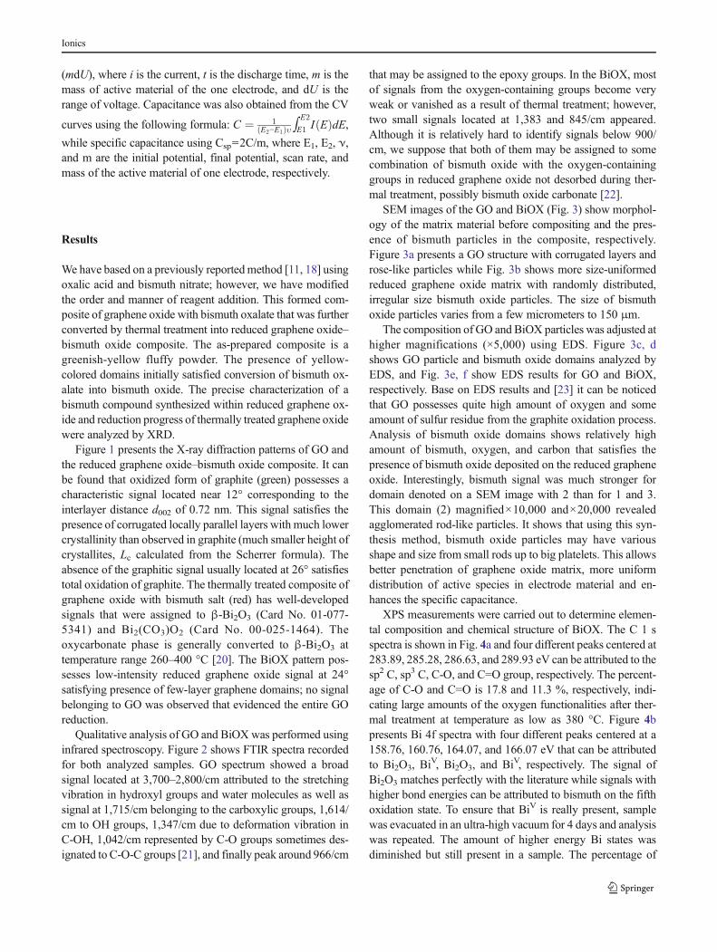
Figure 1 presents the X-ray diffraction patterns of GO andthe reduced graphene oxide–bismuth oxide composite. It canbe found that oxidized form of graphite (green) possesses acharacteristic signal located near 12° corresponding to theinterlayer distance d002 of 0.72 nm. This signal satisfies thepresence of corrugated locally parallel layers with much lowercrystallinity than observed in graphite (much smaller height ofcrystallites, Lc calculated from the Scherrer formula). Theabsence of the graphitic signal usually located at 26° satisfiestotal oxidation of graphite. The thermally treated composite ofgraphene oxide with bismuth salt (red) has well-developedsignals that were assigned to β-Bi2O3 (Card No. 01-077-5341) and Bi2(CO3)O2 (Card No. 00-025-1464). Theoxycarbonate phase is generally converted to β-Bi2O3 attemperature range 260–400 °C [20]. The BiOX pattern pos-sesses low-intensity reduced graphene oxide signal at 24°satisfying presence of few-layer graphene domains; no signalbelonging to GO was observed that evidenced the entire GOreduction.
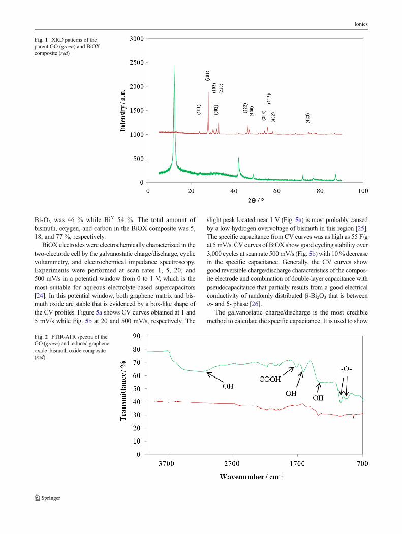
Qualitative analysis of GO and BiOX was performed usinginfrared spectroscopy. Figure 2 shows FTIR spectra recordedfor both analyzed samples. GO spectrum showed a broadsignal located at 3,700–2,800/cm attributed to the stretchingvibration in hydroxyl groups and water molecules as well assignal at 1,715/cm belonging to the carboxylic groups, 1,614/cm to OH groups, 1,347/cm due to deformation vibration inC-OH, 1,042/cm represented by C-O groups sometimes des-ignated to C-O-C groups [21], and finally peak around 966/cm
that may be assigned to the epoxy groups. In the BiOX, mostof signals from the oxygen-containing groups become veryweak or vanished as a result of thermal treatment; however,two small signals located at 1,383 and 845/cm appeared.Although it is relatively hard to identify signals below 900/cm, we suppose that both of them may be assigned to somecombination of bismuth oxide with the oxygen-containinggroups in reduced graphene oxide not desorbed during ther-mal treatment, possibly bismuth oxide carbonate [22].
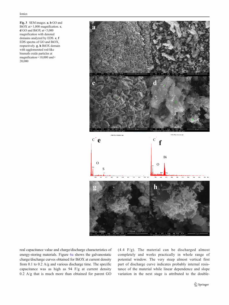
SEM images of the GO and BiOX (Fig. 3) show morphol-ogy of the matrix material before compositing and the pres-ence of bismuth particles in the composite, respectively.Figure 3a presents a GO structure with corrugated layers androse-like particles while Fig. 3b shows more size-uniformedreduced graphene oxide matrix with randomly distributed,irregular size bismuth oxide particles. The size of bismuthoxide particles varies from a few micrometers to 150 μm.
The composition of GO and BiOX particles was adjusted athigher magnifications (×5,000) using EDS. Figure 3c, dshows GO particle and bismuth oxide domains analyzed byEDS, and Fig. 3e, f show EDS results for GO and BiOX,respectively. Base on EDS results and [23] it can be noticedthat GO possesses quite high amount of oxygen and someamount of sulfur residue from the graphite oxidation process.Analysis of bismuth oxide domains shows relatively highamount of bismuth, oxygen, and carbon that satisfies thepresence of bismuth oxide deposited on the reduced grapheneoxide. Interestingly, bismuth signal was much stronger fordomain denoted on a SEM image with 2 than for 1 and 3.This domain (2) magnified×10,000 and×20,000 revealedagglomerated rod-like particles. It shows that using this syn-thesis method, bismuth oxide particles may have variousshape and size from small rods up to big platelets. This allowsbetter penetration of graphene oxide matrix, more uniformdistribution of active species in electrode material and en-hances the specific capacitance.
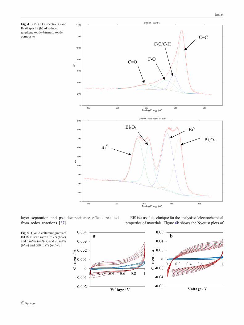
XPS measurements were carried out to determine elemen-tal composition and chemical structure of BiOX. The C 1 sspectra is shown in Fig. 4a and four different peaks centered at283.89, 285.28, 286.63, and 289.93 eV can be attributed to thesp2 C, sp3 C, C-O, and C=O group, respectively. The percent-age of C-O and C=O is 17.8 and 11.3 %, respectively, indi-cating large amounts of the oxygen functionalities after ther-mal treatment at temperature as low as 380 °C. Figure 4bpresents Bi 4f spectra with four different peaks centered at a158.76, 160.76, 164.07, and 166.07 eV that can be attributedto Bi2O3, Bi
V, Bi2O3, and BiV, respectively. The signal ofBi2O3 matches perfectly with the literature while signals withhigher bond energies can be attributed to bismuth on the fifthoxidation state. To ensure that BiV is really present, samplewas evacuated in an ultra-high vacuum for 4 days and analysiswas repeated. The amount of higher energy Bi states wasdiminished but still present in a sample. The percentage of
Ionics
Bi2O3 was 46 % while BiV 54 %. The total amount ofbismuth, oxygen, and carbon in the BiOX composite was 5,18, and 77 %, respectively.
BiOX electrodes were electrochemically characterized in thetwo-electrode cell by the galvanostatic charge/discharge, cyclicvoltammetry, and electrochemical impedance spectroscopy.Experiments were performed at scan rates 1, 5, 20, and500 mV/s in a potential window from 0 to 1 V, which is themost suitable for aqueous electrolyte-based supercapacitors[24]. In this potential window, both graphene matrix and bis-muth oxide are stable that is evidenced by a box-like shape ofthe CV profiles. Figure 5a shows CV curves obtained at 1 and5 mV/s while Fig. 5b at 20 and 500 mV/s, respectively. The
slight peak located near 1 V (Fig. 5a) is most probably causedby a low-hydrogen overvoltage of bismuth in this region [25].The specific capacitance from CV curves was as high as 55 F/gat 5mV/s. CV curves of BiOX show good cycling stability over3,000 cycles at scan rate 500mV/s (Fig. 5b) with 10% decreasein the specific capacitance. Generally, the CV curves showgood reversible charge/discharge characteristics of the compos-ite electrode and combination of double-layer capacitance withpseudocapacitance that partially results from a good electricalconductivity of randomly distributed β-Bi2O3 that is betweenα- and δ- phase [26].
The galvanostatic charge/discharge is the most crediblemethod to calculate the specific capacitance. It is used to show
Fig. 1 XRD patterns of theparent GO (green) and BiOXcomposite (red)
Fig. 2 FTIR-ATR spectra of theGO (green) and reduced grapheneoxide–bismuth oxide composite(red)
Ionics
real capacitance value and charge/discharge characteristics ofenergy-storing materials. Figure 6a shows the galvanostaticcharge/discharge curves obtained for BiOX at current densityfrom 0.1 to 0.2 A/g and various discharge time. The specificcapacitance was as high as 94 F/g at current density0.2 A/g that is much more than obtained for parent GO
(4.4 F/g). The material can be discharged almostcompletely and works practically in whole range ofpotential window. The very steep almost vertical firstpart of discharge curve indicates probably internal resis-tance of the material while linear dependence and slopevariation in the next stage is attributed to the double-
Fig. 3 SEM images. a, bGO andBiOX at×1,000 magnification. c,d GO and BiOX at×5,000magnification with denoteddomains analyzed by EDS. e, fEDS spectra of GO and BiOX,respectively. g, h BiOX domainwith agglomerated rod-likebismuth oxide particles atmagnification×10,000 and×20,000
Ionics
layer separation and pseudocapacitance effects resultedfrom redox reactions [27].
EIS is a useful technique for the analysis of electrochemicalproperties of materials. Figure 6b shows the Nyquist plots of
Fig. 4 XPS C 1 s spectra (a) andBi 4f spectra (b) of reducedgraphene oxide–bismuth oxidecomposite
Fig. 5 Cyclic voltammograms ofBiOX at scan rate: 1 mV/s (blue)and 5 mV/s (red) (a) and 20 mV/s(blue) and 500 mV/s (red) (b)
Ionics
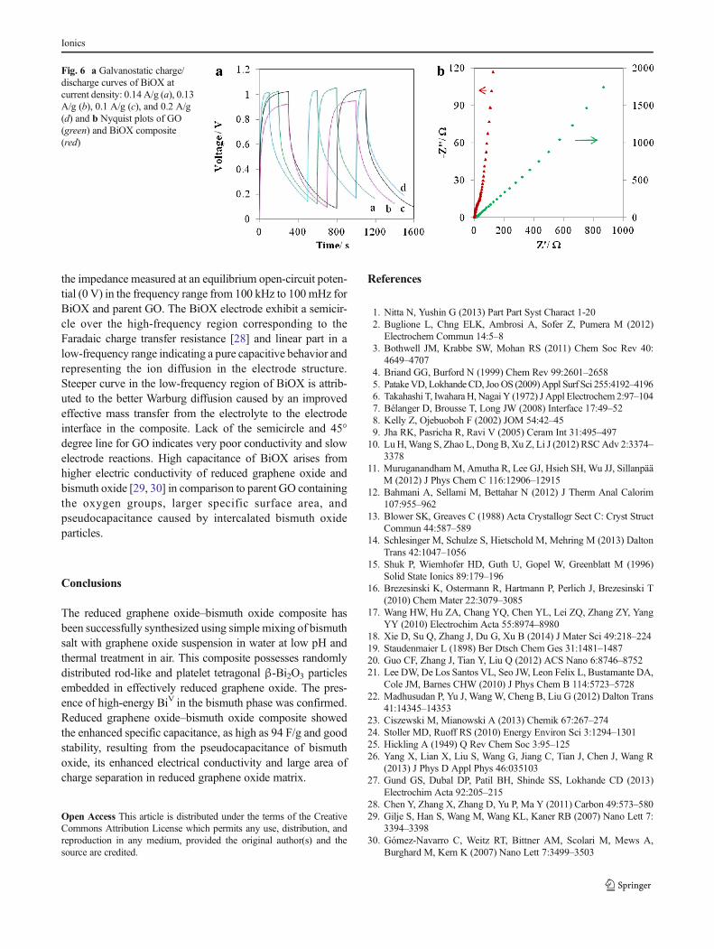
the impedance measured at an equilibrium open-circuit poten-tial (0 V) in the frequency range from 100 kHz to 100 mHz forBiOX and parent GO. The BiOX electrode exhibit a semicir-cle over the high-frequency region corresponding to theFaradaic charge transfer resistance [28] and linear part in alow-frequency range indicating a pure capacitive behavior andrepresenting the ion diffusion in the electrode structure.Steeper curve in the low-frequency region of BiOX is attrib-uted to the better Warburg diffusion caused by an improvedeffective mass transfer from the electrolyte to the electrodeinterface in the composite. Lack of the semicircle and 45°degree line for GO indicates very poor conductivity and slowelectrode reactions. High capacitance of BiOX arises fromhigher electric conductivity of reduced graphene oxide andbismuth oxide [29, 30] in comparison to parent GO containingthe oxygen groups, larger specific surface area, andpseudocapacitance caused by intercalated bismuth oxideparticles.
Conclusions
The reduced graphene oxide–bismuth oxide composite hasbeen successfully synthesized using simple mixing of bismuthsalt with graphene oxide suspension in water at low pH andthermal treatment in air. This composite possesses randomlydistributed rod-like and platelet tetragonal β-Bi2O3 particlesembedded in effectively reduced graphene oxide. The pres-ence of high-energy BiV in the bismuth phase was confirmed.Reduced graphene oxide–bismuth oxide composite showedthe enhanced specific capacitance, as high as 94 F/g and goodstability, resulting from the pseudocapacitance of bismuthoxide, its enhanced electrical conductivity and large area ofcharge separation in reduced graphene oxide matrix.
Open Access This article is distributed under the terms of the CreativeCommons Attribution License which permits any use, distribution, andreproduction in any medium, provided the original author(s) and thesource are credited.
References
1. Nitta N, Yushin G (2013) Part Part Syst Charact 1-202. Buglione L, Chng ELK, Ambrosi A, Sofer Z, Pumera M (2012)
Electrochem Commun 14:5–83. Bothwell JM, Krabbe SW, Mohan RS (2011) Chem Soc Rev 40:
4649–47074. Briand GG, Burford N (1999) Chem Rev 99:2601–26585. PatakeVD, LokhandeCD, JooOS (2009)Appl Surf Sci 255:4192–41966. Takahashi T, IwaharaH, Nagai Y (1972) J Appl Electrochem 2:97–1047. Bélanger D, Brousse T, Long JW (2008) Interface 17:49–528. Kelly Z, Ojebuoboh F (2002) JOM 54:42–459. Jha RK, Pasricha R, Ravi V (2005) Ceram Int 31:495–497
10. LuH,Wang S, Zhao L, Dong B, Xu Z, Li J (2012) RSCAdv 2:3374–3378
11. MuruganandhamM, Amutha R, Lee GJ, Hsieh SH, Wu JJ, SillanpääM (2012) J Phys Chem C 116:12906–12915
12. Bahmani A, Sellami M, Bettahar N (2012) J Therm Anal Calorim107:955–962
13. Blower SK, Greaves C (1988) Acta Crystallogr Sect C: Cryst StructCommun 44:587–589
14. Schlesinger M, Schulze S, Hietschold M, Mehring M (2013) DaltonTrans 42:1047–1056
15. Shuk P, Wiemhofer HD, Guth U, Gopel W, Greenblatt M (1996)Solid State Ionics 89:179–196
16. Brezesinski K, Ostermann R, Hartmann P, Perlich J, Brezesinski T(2010) Chem Mater 22:3079–3085
17. Wang HW, Hu ZA, Chang YQ, Chen YL, Lei ZQ, Zhang ZY, YangYY (2010) Electrochim Acta 55:8974–8980
18. Xie D, Su Q, Zhang J, Du G, Xu B (2014) J Mater Sci 49:218–22419. Staudenmaier L (1898) Ber Dtsch Chem Ges 31:1481–148720. Guo CF, Zhang J, Tian Y, Liu Q (2012) ACS Nano 6:8746–875221. Lee DW, De Los Santos VL, Seo JW, Leon Felix L, Bustamante DA,
Cole JM, Barnes CHW (2010) J Phys Chem B 114:5723–572822. Madhusudan P, Yu J, Wang W, Cheng B, Liu G (2012) Dalton Trans
41:14345–1435323. Ciszewski M, Mianowski A (2013) Chemik 67:267–27424. Stoller MD, Ruoff RS (2010) Energy Environ Sci 3:1294–130125. Hickling A (1949) Q Rev Chem Soc 3:95–12526. Yang X, Lian X, Liu S, Wang G, Jiang C, Tian J, Chen J, Wang R
(2013) J Phys D Appl Phys 46:03510327. Gund GS, Dubal DP, Patil BH, Shinde SS, Lokhande CD (2013)
Electrochim Acta 92:205–21528. Chen Y, Zhang X, Zhang D, Yu P, Ma Y (2011) Carbon 49:573–58029. Gilje S, Han S, Wang M, Wang KL, Kaner RB (2007) Nano Lett 7:
3394–339830. Gómez-Navarro C, Weitz RT, Bittner AM, Scolari M, Mews A,
Burghard M, Kern K (2007) Nano Lett 7:3499–3503
Fig. 6 a Galvanostatic charge/discharge curves of BiOX atcurrent density: 0.14 A/g (a), 0.13A/g (b), 0.1 A/g (c), and 0.2 A/g(d) and b Nyquist plots of GO(green) and BiOX composite(red)
Ionics
![Comparative Corrosion Study of Austenitic AISI 304L and ......electrode. The studied samples, made of austenitic steel, were used as working electrodes [20-27]. The electrochemical](https://static.fdocuments.pl/doc/165x107/5ff575e964f5302a2f50fbea/comparative-corrosion-study-of-austenitic-aisi-304l-and-electrode-the-studied.jpg)