PROYECTO FIN DE GRADOoa.upm.es/63431/1/TFG_FRANCELLY_KATHERIN_CANO_LADINO.pdf · 9 Background The...
66
ESCUELA TÉCNICA SUPERIOR DE INGENIERÍA Y SISTEMAS DE TELECOMUNICACIÓN PROYECTO FIN DE GRADO TÍTULO: Development and characterization of current controller for studies of MR dampers AUTOR: Francelly Katherine Cano Ladino TITULACIÓN: Grado en Ingeniería Electrónica de las Comunicaciones TUTOR: Janusz Goldasz UNIVERSIDAD: Politechnika Krakowska im. Tadeusza Kosciuszki CENTRO: Faculty of Electrical and Computing Engineering PAÍS: Polonia Fecha de lectura: 24 de abril de 2019 Calificación: El coordinador de movilidad,
Transcript of PROYECTO FIN DE GRADOoa.upm.es/63431/1/TFG_FRANCELLY_KATHERIN_CANO_LADINO.pdf · 9 Background The...
ESCUELA TÉCNICA SUPERIOR DE INGENIERÍA Y
SISTEMAS DE TELECOMUNICACIÓN
PROYECTO FIN DE GRADO
TÍTULO: Development and characterization of current controller for studies of
MR dampers
AUTOR: Francelly Katherine Cano Ladino
TITULACIÓN: Grado en Ingeniería Electrónica de las Comunicaciones
TUTOR: Janusz Goldasz
UNIVERSIDAD: Politechnika Krakowska im. Tadeusza Kosciuszki
CENTRO: Faculty of Electrical and Computing Engineering
PAÍS: Polonia
Fecha de lectura: 24 de abril de 2019
Calificación:
El coordinador de movilidad,

1
2
Resumen La necesidad de mejorar los diferentes atributos de las máquinas, nos llevan a buscar soluciones fáciles y prácticas para conocer su comportamiento. Debido a esto, los contro-ladores son parte esencial de la investigación para mejorar las prestaciones de diversos productos. En nuestro caso se desarrolla e implementa un controlador de corriente para la alimentación de un amortiguador MR (Magneto-Rheological). Los amortiguadores MR son uno de los amortiguadores que más desarrollo e investiga-ción se está realizando dado a la variedad de aplicaciones en las que les puede dar uso como ingeniería civil, mecánica, automotriz, entre otras. Por este motivo, la necesidad de implementar controladores de bajo costo con elementos más eficientes propone a los in-genieros buscar nuevos métodos para estudiar su comportamiento. El uso de microcon-troladores favorece al desarrollo de los mismos debido a la amplia variedad que se tiene a disposición, y los recursos que proporcionan los fabricantes. Por eso ha resultado tan llamativo realizar los controladores mediante el uso de algoritmos y elementos de poten-cia para el estudio de los amortiguadores. Para el desarrollo de este proyecto se van a especificar los elementos que lo componen: controlador PI (Proporcional Integral), la etapa de potencia que lo componen señales PWM (Pulse-width modulation ) y un H-Bridge, el microcontrolador de la familia STMi-croelectronics de la serie STMF7, una interfaz que se utiliza una pantalla táctil y el pistón del amortiguador MR, se ha optado sólo usar el pistón ya que es donde se encuentra alo-jado tanto la bobina y la resistencia, sólo necesitamos ver su comportamiento durante la fase de alimentación. Palabras clave: amortiguadores MR, controlador de corriente, etapa de potencia, PWM, H-Bridge, fuente de alimentación, controlador discreto, sistema embebido.
3
Abstract The need to improve the different attributes of the machines, lead us to find easy and practical solutions to know their behavior. Due to this, drivers are an essential part of the research to improve the performance of various products. In our case we develops and implements a driver power supply for the a MR shock absorber (Magneto-Rheological). Magnetorheological shock absorbers are one of the most developed and research shock absorbers given to the variety of applications in which they can be used as civil engineer-ing, mechanics, automotive, among others. For this reason, the need to implement low-cost drivers with more efficient elements suggests that to look for new methods to study their behaviour. The use of microcontrollers favors the development of the same due to the wide variety that is available, and the resources that the manufacturers provide. That is why it has been so striking to carry out the controllers by using algorithms and power elements to study the shock absorbers. For the development of this project are going to specify the elements that compose it: Controller PI (Proportional-Integral), the stage of power that compose the signals PWM (Pulse-width modulation) and H-bridge, the microcontroller of the family STMicroelec-tronics from the STMF7 series, an interface that uses a touch screen and the shocker pis-ton MR, it has opted to only use the piston as it is where it is hosted both the coil and the resistance, we just need to see their behavior during the feeding phase.
Keywords: MR dampers, Current controller, Power stage, PWM, H-Bridge, power sup-ply, discrete time controller, embedded system.
4
Content Resumen ........................................................................................................................................ 2
Abstract ......................................................................................................................................... 3
Figures ........................................................................................................................................... 5
Tables ............................................................................................................................................ 6
Acronyms ...................................................................................................................................... 7
Introduction ................................................................................................................................... 8
Background ................................................................................................................................... 9
Design Specifications and Restrictions ....................................................................................... 10
Description of the proposed solution .......................................................................................... 11
1. PI Controller ................................................................................................................ 12
2. Sampling time ............................................................................................................. 17
3. Power Stage: ................................................................................................................ 17
3.1. PWM ....................................................................................................................... 18
3.2. H_Bridge: ............................................................................................................... 21
4. Analog to Digital Converter ........................................................................................ 24
5. Interface ....................................................................................................................... 25
6. Microcontroller............................................................................................................ 27
7. Development tools....................................................................................................... 28
8. Shock Absorber MR .................................................................................................... 30
Current controller ........................................................................................................................ 31
1. Hardware ..................................................................................................................... 32
2. Software ...................................................................................................................... 36
Budget ......................................................................................................................................... 40
Conclusions ................................................................................................................................. 41
List of references ......................................................................................................................... 42
Annex .......................................................................................................................................... 44
5
Figures Figure 1. Basic structure of the current controller ...................................................................... 11
Figure 2. Place of roots of the PI controller transfer function .................................................... 13
Figure 3. Pi controller study using Bode diagram ....................................................................... 14
Figure 4. Place of Roots of the complete system Pi controller and the plant............................. 14
Figure 5. System-wide transfer function. .................................................................................... 15
Figure 6. Discrete Pi serial controller .......................................................................................... 16
Figure 7. Power stage outline ..................................................................................................... 17
Figure 8. PWM input and output forms [6] ................................................................................. 18
Figures 9. Waveforms of the PWM signal behavior. ................................................................... 20
Figure 10. H-Bridge [16] .............................................................................................................. 21
Figure 11. H-Bridge Performance [17] ........................................................................................ 21
Figure 12. H-Bridge Driver developed by Pololu [10]. ................................................................. 22
Figure 13. Pin CS of the H-Bridge ................................................................................................ 23
Figure 14. Voltage Regulator U3V70F12. .................................................................................... 23
Figure 15. ADC behavior [18] ...................................................................................................... 24
Figure 16. Screen lcd B-LCD40-DSI1 ............................................................................................ 25
Figure 17. STM32F69I-DISCOVERY Microcontroller .................................................................... 27
Figure 18. CN3 Pin to set the microcontroller's power mode..................................................... 27
Figure 19. Configuration of the card, aspects like range memory, generation of the code. ...... 28
Figure 20. Flash settings. is located in Debug->Settings ............................................................. 29
Figure 21. RCC configuration with STMCube .............................................................................. 29
Figure 22. MR Shock absorber. ................................................................................................... 30
Figure 23. Current controller-specific flow diagram. .................................................................. 31
Figure 24. Full system view together .......................................................................................... 33
Figure 25. Sample of the signals in the case of chirp excitation ................................................. 34
Figure 26. Signals in the case of the sine signal excitation ......................................................... 34
Figure 27. Signals in the case of the Square excitation ............................................................... 35
Figure 28. Signal settings chirp .................................................................................................... 37
Figure 29. Setting the Signal square ............................................................................................ 38
Figure 30. Sine signal Settings ..................................................................................................... 38
Figure 31. Algorithm flow diagram performed. .......................................................................... 39
6
Tables Table 1. Value of the passive elements for the shock plant ....................................................... 12
Table 2. Value of the Pi driver's continuous earnings ................................................................. 13
Table 3. Discrete gains for the Pi controller ................................................................................ 16
Table 4. VNH2SP30 Specifications ............................................................................................... 22
Table 5. Specifications of U3V70F12 ........................................................................................... 23
Table 6. Specifications of the Screen LCD B-LCD40-DSI1 ............................................................ 25
Table 7. Pin layout in microcontroller [Annex 1, 2]..................................................................... 32
Table 8. Power connection for H-Bridge ..................................................................................... 32
Table 9. H-Bridge Connection ..................................................................................................... 32
Table 10. Budget ......................................................................................................................... 40
7
Acronyms PWM Pulse-width modulation. ADC Analog-to-digital conversion. KEIL Is the complete software development environment for a wide range of
Arm Cortex- M based microcontroller devices.
STMCUBEMx Is a graphical tool for STM32 microcontrollers.
STM32 The STM32 family of 32-bit Flash microcontrollers based on the Arm Cortex-M.
LCD Liquid Cristal Display. PI Proportional-Integral. MR Magneto-Rheological. MPU Memory Protection Unit. SDRAM Synchronous Dynamic Random-Access Memory.
FMC Flexible Memory Controller. RAM Random Access Memory. HAL Hardware Abstraction Layer. ART Chrome-ART Accelerator. emWin Embedded Graphics Library from SEGGER GUI Graphical User Interface.

8
Introduction
The utility of MR dampers in the reduction of vibrations turning it into a controller with an intelligent suspension is, due to the use of MR fluid that responds to a magnetic field that is generated to from the current supplied to the coil containing our piston, moving from a liquid state to semi-solid in a very short time. This quick response is a valuable advantage that drives to develop more research on their behavior because it can be used in different areas of engineering. This document is divided into five parts. The first one corresponds to the background and specifications and restrictions of the design, which discusses the elements necessary for the implementation of the current controller. The second part remember the development of the solution adopted, detailing a little more about the choice of each element that inte-grates it, the reasons for the choice for example of the discreet controller compared to the analog, one based on the use of the microcontroller, features that has the power stage with the PWM signal and the H-Bridge, the ADC (Analog-to-digital conversion), the controller interface that uses the touch screen that owns the microcontroller itself and that in turn uses the GUI (Graphical User Interface) resources of emWin (Embedded Graphics Library from SEGGER), also discusses the development environment in which it work to implement the system code. The third part is the current controller already complete, showing the results that have been obtained, and the aspect of the system in general. The fourth part several the budget that has been needed to carry out the project. And the last one is the conclusion that it get with the project.
9
Background The need to control processes without knowing a priori his behavior, urges engineers to seek solutions to improve their performance and benefits. The reason for this project is to make a current controller for a controlled of shock absorber, which one it is used to power supply. Between the different types of shocks that exist MR damper is used. The damper uses a special fluid that gives them the advantages as easy, quick response between the elec-tronic control part and the mechanics, among many others [1]. Our work focuses more on the study of the current controller of this type of shock absorb-ers, given that several studies have shown that a current controller helps to decrease the response time of the shock absorbers [2]. The driver implementation is done in closed loop because it is more useful and important to know the comparison of the output with the input to provide a better fit to our control system, making the system more robust due to possible perturbances . For the development of our controller, it will be used an embedded system of 32 bits that will function as the core of our project, that is one of the reason to implement a discrete driver.

10
Design Specifications and Restrictions The objective of this project consists mainly in the study and development of a current controller using a microcontroller STM32, but for this we will need to create a closed loop control system to study the behavior that has the current in the circuit that models the shock absorber, a response RL circuit or with a real MR shock absorber. To carry out the project we will need the following elements:
• A PI controller is required to be the first starting point of our control system, which will be responsible for regulating the working cycle of a PWM driver based on the measurement error of the current in the shock absorber and the current of input reference. It will be implemented by a software using the STM32 microcontroller
• We will also need a PWM driver that works at a frequency above 20 kHz; in principle it is proposed to implement it with the timers that the microcontroller has available.
• A H-bridge driver that can handle currents up to 5 A, if we want to test two shock absorbers.
• A current sensor will be needed to be the feedback of our circuit, but for this it will also be necessary an analog to digital converter to make the appropriate checks in the control system.
• A user interface using the STM32F769I-DISCO LCD (Liquid Cristal Display). • The microcontroller belonging to the family of STM32. It has many resources for
programming such as libraries HAL, which allows it to be used in a lot of different projects.
• The C programming language will be used to work with the STM32 board.
11
Description of the proposed solution Between the implementation of an analog or digital controller, it has opted for a digital controller because when using a microcontroller is much easier to do, as well as it has the advantages of:
• precision, input signals can be read by analog/digital converters of e.g. 12 bits or more.
• to calculate the error our accomplishment requires only following the nec-essary mathematical operations.
• It can be easily adjusted, as its construction is through software, not hard-ware as in the case of analog controllers that depend on resistors, capacitors, etc.
• The speed with which the error can be found, since being developed through a microcontroller, the sampling can be a relatively small time to check the correct functioning of the systems.
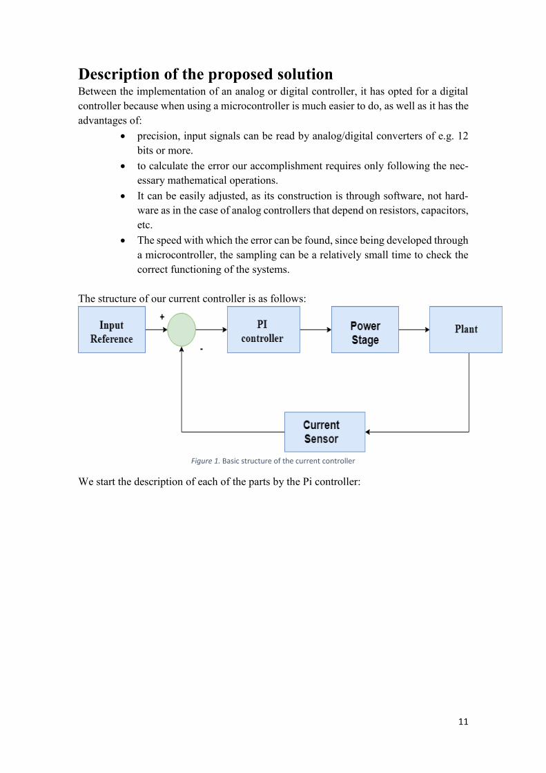
The structure of our current controller is as follows:
Figure 1. Basic structure of the current controller
We start the description of each of the parts by the Pi controller:
12
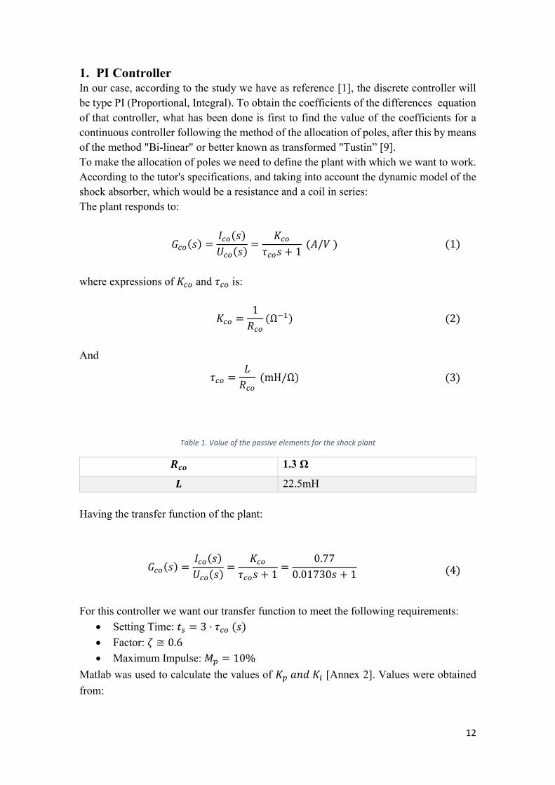
1. PI Controller In our case, according to the study we have as reference [1], the discrete controller will be type PI (Proportional, Integral). To obtain the coefficients of the differences equation of that controller, what has been done is first to find the value of the coefficients for a continuous controller following the method of the allocation of poles, after this by means of the method "Bi-linear" or better known as transformed "Tustin” [9]. To make the allocation of poles we need to define the plant with which we want to work. According to the tutor's specifications, and taking into account the dynamic model of the shock absorber, which would be a resistance and a coil in series: The plant responds to:
𝐺𝑐𝑜(𝑠) =𝐼𝑐𝑜(𝑠)
𝑈𝑐𝑜(𝑠)=
𝐾𝑐𝑜
𝜏𝑐𝑜𝑠 + 1 (𝐴/𝑉 ) (1)
where expressions of 𝐾𝑐𝑜 and 𝜏𝑐𝑜 is:
𝐾𝑐𝑜 =1
𝑅𝑐𝑜(Ω−1) (2)
And
𝜏𝑐𝑜 =𝐿
𝑅𝑐𝑜 (mH/Ω) (3)
Table 1. Value of the passive elements for the shock plant
𝑹𝒄𝒐 1.3 Ω
𝑳 22.5mH Having the transfer function of the plant:
𝐺𝑐𝑜(𝑠) =𝐼𝑐𝑜(𝑠)
𝑈𝑐𝑜(𝑠)=
𝐾𝑐𝑜
𝜏𝑐𝑜𝑠 + 1=
0.77
0.01730𝑠 + 1 (4)
For this controller we want our transfer function to meet the following requirements:
• Setting Time: 𝑡𝑠 = 3 · 𝜏𝑐𝑜 (𝑠) • Factor: 𝜁 ≅ 0.6 • Maximum Impulse: 𝑀𝑝 = 10%
Matlab was used to calculate the values of 𝐾𝑝 𝑎𝑛𝑑 𝐾𝑖 [Annex 2]. Values were obtained from:
13
Table 2. Value of the Pi driver's continuous earnings
𝑲𝒑 𝟏. 𝟒𝟐𝟏𝟑Ω−𝟏
𝑲𝒊 235.5687Ω−1
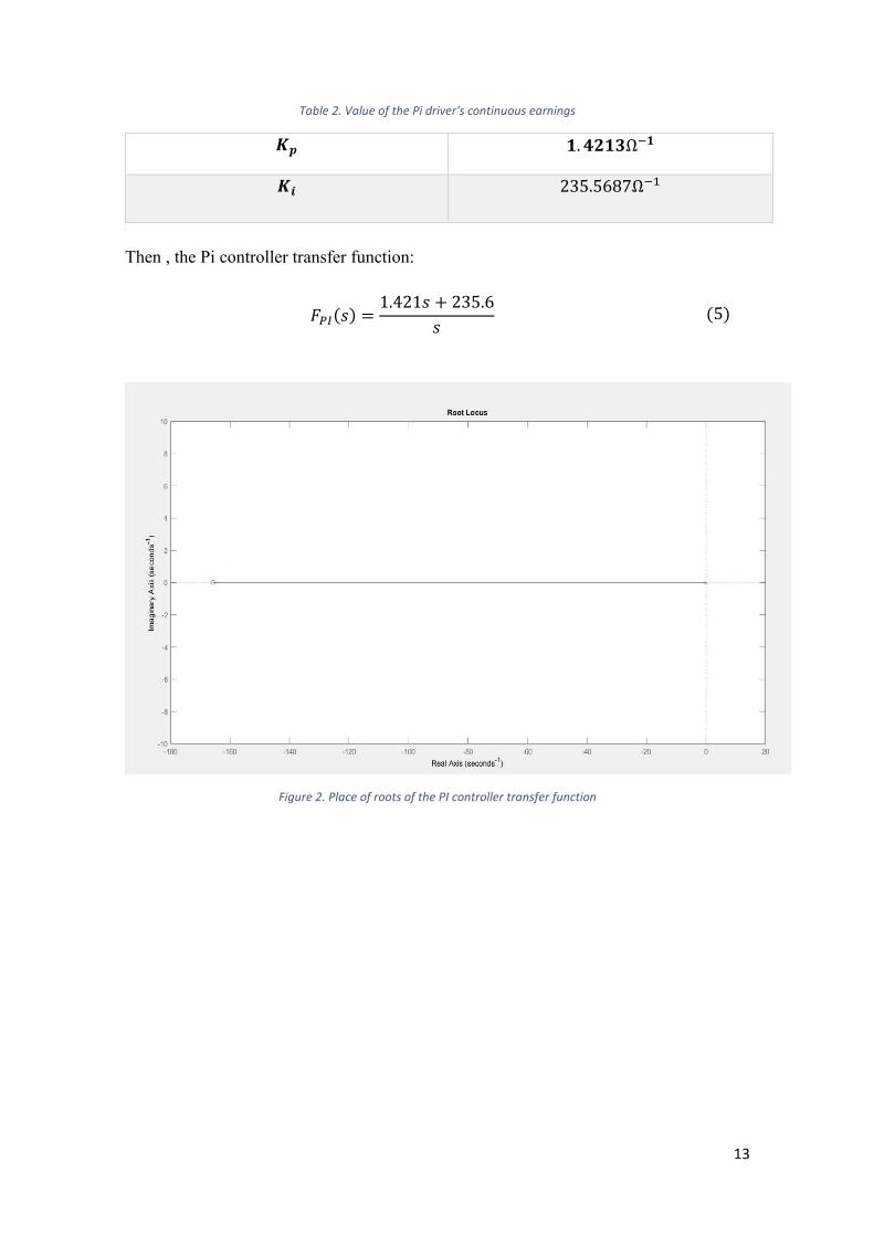
Then , the Pi controller transfer function:
𝐹𝑃𝐼(𝑠) =1.421𝑠 + 235.6
𝑠 (5)
Figure 2. Place of roots of the PI controller transfer function
14
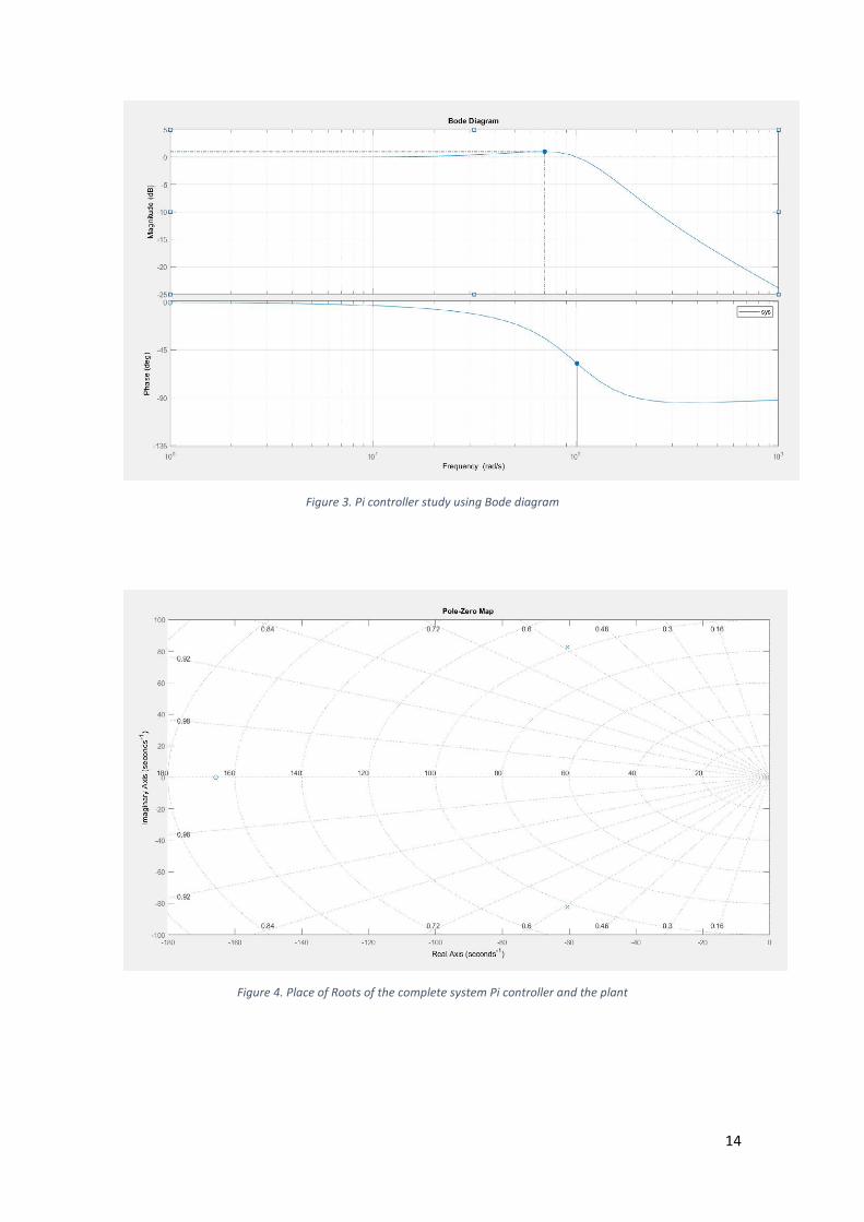
Figure 3. Pi controller study using Bode diagram
Figure 4. Place of Roots of the complete system Pi controller and the plant
15
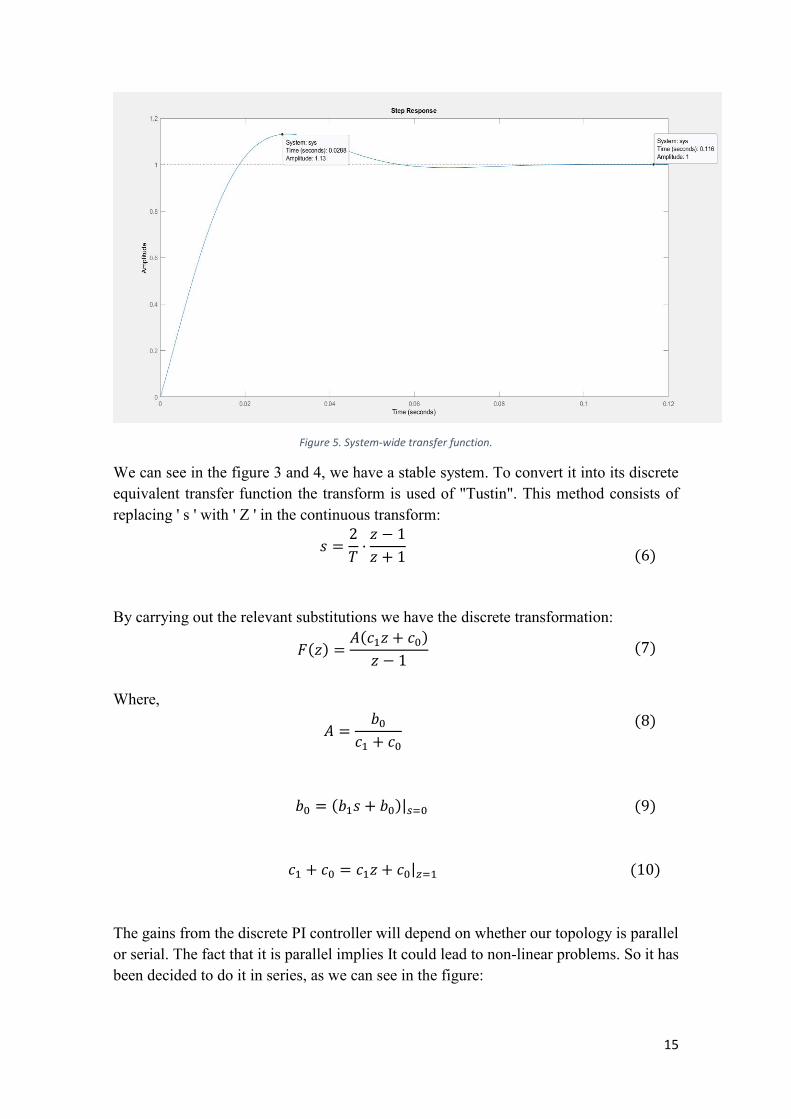
Figure 5. System-wide transfer function.
We can see in the figure 3 and 4, we have a stable system. To convert it into its discrete equivalent transfer function the transform is used of "Tustin". This method consists of replacing ' s ' with ' Z ' in the continuous transform:
𝑠 =2
𝑇·
𝑧 − 1
𝑧 + 1
(6)
By carrying out the relevant substitutions we have the discrete transformation:
𝐹(𝑧) =𝐴(𝑐1𝑧 + 𝑐0)
𝑧 − 1 (7)
Where,
𝐴 =𝑏0
𝑐1 + 𝑐0 (8)
𝑏0 = (𝑏1𝑠 + 𝑏0)|𝑠=0 (9)
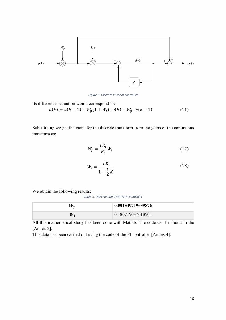
𝑐1 + 𝑐0 = 𝑐1𝑧 + 𝑐0|𝑧=1 (10) The gains from the discrete PI controller will depend on whether our topology is parallel or serial. The fact that it is parallel implies It could lead to non-linear problems. So it has been decided to do it in series, as we can see in the figure:
16
Figure 6. Discrete Pi serial controller
Its differences equation would correspond to: 𝑢(𝑘) = 𝑢(𝑘 − 1) + 𝑊𝑝(1 + 𝑊𝑖) · 𝑒(𝑘) − 𝑊𝑝 · 𝑒(𝑘 − 1) (11)
Substituting we get the gains for the discrete transform from the gains of the continuous transform as:
𝑊𝑝 =𝑇𝐾𝑖
𝐾𝑖𝑊𝑖 (12)
𝑊𝑖 =𝑇𝐾𝑖
1 −𝑇2 𝐾𝑖
(13)
We obtain the following results:
Table 3. Discrete gains for the Pi controller
𝑾𝒑 0.001549719639876
𝑾𝒊 0.180719047618901
All this mathematical study has been done with Matlab. The code can be found in the [Annex 2]. This data has been carried out using the code of the PI controller [Annex 4].
17
2. Sampling time Using a discrete controller implicitly requires sampling operations. Periodic sampling has been chosen for this system. If we have a small sampling period, we can get the controller to behave very much like a continuous control. The sampling to be used is by interruption. One of the factors to take into account is aliasing, which is a problem that should be avoided during the sampling process and that means that the original signal cannot be retrieved from the sampled signal. Using the Shannon-Nyquist theorem is intended to avoid this problem.
𝑓𝑚 > 2 · 𝑓𝑠𝑖𝑔𝑛𝑎𝑙
(14)
The sampling time has been chosen to be 1 𝑚𝑠 following as reference [1].
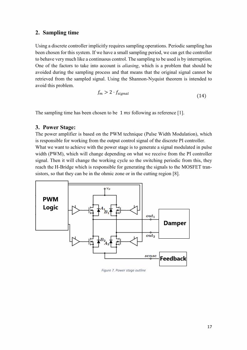
3. Power Stage: The power amplifier is based on the PWM technique (Pulse Width Modulation), which is responsible for working from the output control signal of the discrete PI controller. What we want to achieve with the power stage is to generate a signal modulated in pulse width (PWM), which will change depending on what we receive from the PI controller signal. Then it will change the working cycle so the switching periodic from this, they reach the H-Bridge which is responsible for generating the signals to the MOSFET tran-sistors, so that they can be in the ohmic zone or in the cutting region [8].
Figure 7. Power stage outline

18
3.1. PWM A PWM signal technique, depending on the input signal to the output, there is a pulse train that has the same amplitude with different pulse widths, corresponding to that input signal. This requires a sawtooth signal to perform the comparison with the modulator signal which can be a periodic signal such as (sinusoid, Square, etc.) (Figure 8)
Figure 8. PWM input and output forms [6]
A discrete controller output requires an element that reconstructs the digital signal as our plant remains continuous. PWM is used because due to it is modulating property, we can also control the H-Bridge driver controlling the current passing through the transistors. This way we can control the power supplied to electrical devices, which in our case is the shock absorber. Both make up our power stage. This has been chosen to use one of the PWM output signals of the microcontroller itself. PWM TIM1_CH4
It has been used in the group of advanced control timer (TIM1/TIM8), in particular the (Timer 1 Channel 4). These timers have the feature of using 16 bits for the account, con-trolled by a prescaler programmable. These timers allow we to measure PWM signals or also to generate them, which is what is required for this project. In the project what has been done is for each output in each sampling period the work cycle of the PWM is changed. Of the advantages of using the PWM, the power loss is very low due to the switching of the pins [1]. The generation of the PWM signal in our code has been done globally, it contains 3 main functions. The first is in charge of initializing the Timer which is responsible for defining

19
the parameters necessary to generate the signal, MX_TIM1_Init(), as the value of the pre-scaler, the period of the counter. The next function that is in the file stm32f7xx_hal_msp.c is HAL_TIM_PWM_MspInit() That is in charge of enabling the timer using the macro __HAL_RCC_TIM1_CLK_ENA-BLE(), Below is used the function HAL_TIM_MspPostInit() which allows to set the PIN where It will take out the PWM signal. This defines the PIN, the mode, the speed for the signal output. The last function is in charge of setting the work cycle to take the PWM signal according to the output obtained from the PI controller, set_PWM_duty(float duty). Here we take into account that when using the Channel 4 of the Timer 1, if we want to change the pulse width we have to modify the value of the record TIMx_CCRx, which in our case is the TIM1−>CCR4. Therefore, for each sampling of the signal that will be to generate a value at the output of the PI controller, this value is the one that is entered to that record for the change of the work cycle.
Figure 9.1. Duty cycle around 60% Figure 9.2. Duty cycle around 34 %
20
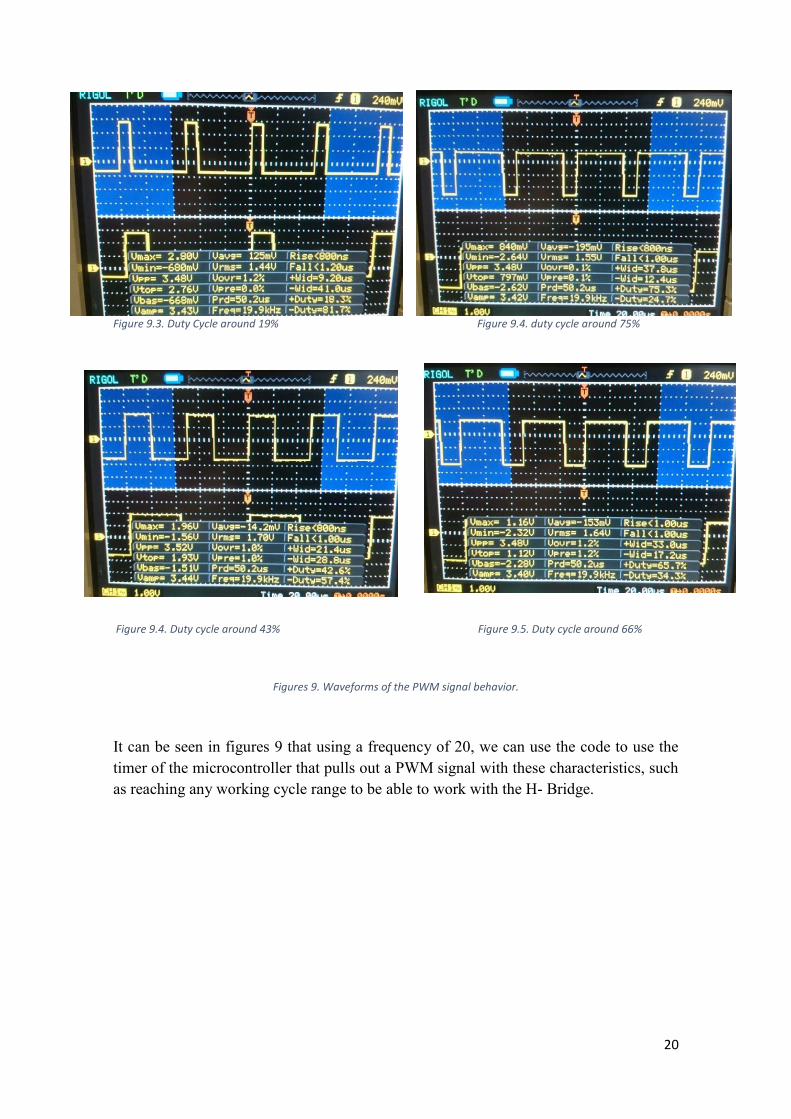
Figure 9.3. Duty Cycle around 19% Figure 9.4. duty cycle around 75%
Figure 9.4. Duty cycle around 43% Figure 9.5. Duty cycle around 66%
Figures 9. Waveforms of the PWM signal behavior.
It can be seen in figures 9 that using a frequency of 20, we can use the code to use the timer of the microcontroller that pulls out a PWM signal with these characteristics, such as reaching any working cycle range to be able to work with the H- Bridge.

21
3.2. H_Bridge: An H-bridge is made up of 4 switching transistors, which inside contains a load that can be a: motor, damper, etc. These transistors can be both MOSFET, in turn have a protection circuit that is usually a Schottky diode. These diodes are used because although the switching of the transistors is not ideal, it allows the circulation of the current when the transistors are closed or open, not to damage the H-Bridge.
Figure 10. H-Bridge [16]
The operating mode must take into account that the switching of the diodes cannot be given in any way and that it has certain restrictions. For example, both the SW1 and SW3, or (SW2 and SW4) transistors cannot be closed at the same time, as they may short-circuit the feed with mass. Normal or waiting operation is that the transistors SW1 and SW4 or SW2 and SW4 are closed at the same time. When this happens, and if in the case that the load is an engine, the direction of rotation will be to one side or another depending on the behavior of the transistors [10] (open or closed).
Figure 11. H-Bridge Performance [17]
22
3.2.1. Device
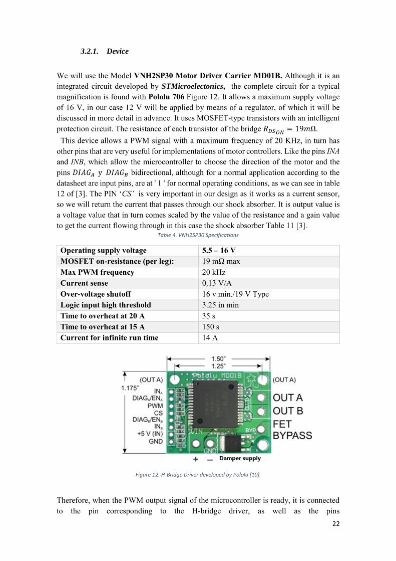
We will use the Model VNH2SP30 Motor Driver Carrier MD01B. Although it is an integrated circuit developed by STMicroelectonics, the complete circuit for a typical magnification is found with Pololu 706 Figure 12. It allows a maximum supply voltage of 16 V, in our case 12 V will be applied by means of a regulator, of which it will be discussed in more detail in advance. It uses MOSFET-type transistors with an intelligent protection circuit. The resistance of each transistor of the bridge 𝑅𝐷𝑆𝑂𝑁
= 19𝑚Ω. This device allows a PWM signal with a maximum frequency of 20 KHz, in turn has other pins that are very useful for implementations of motor controllers. Like the pins INA and INB, which allow the microcontroller to choose the direction of the motor and the pins 𝐷𝐼𝐴𝐺𝐴 y 𝐷𝐼𝐴𝐺𝐵 bidirectional, although for a normal application according to the datasheet are input pins, are at ' 1 ' for normal operating conditions, as we can see in table 12 of [3]. The PIN ‘CS’ is very important in our design as it works as a current sensor, so we will return the current that passes through our shock absorber. It is output value is a voltage value that in turn comes scaled by the value of the resistance and a gain value to get the current flowing through in this case the shock absorber Table 11 [3].
Table 4. VNH2SP30 Specifications
Operating supply voltage 5.5 – 16 V MOSFET on-resistance (per leg): 19 mΩ max Max PWM frequency 20 kHz Current sense 0.13 V/A Over-voltage shutoff 16 v min./19 V Type Logic input high threshold 3.25 in min Time to overheat at 20 A 35 s Time to overheat at 15 A 150 s Current for infinite run time 14 A
Figure 12. H-Bridge Driver developed by Pololu [10].
Therefore, when the PWM output signal of the microcontroller is ready, it is connected to the pin corresponding to the H-bridge driver, as well as the pins
23
𝐼𝑁𝐴 , 𝐼𝑁𝐵, 𝐷𝐼𝐴𝐺𝐴 y 𝐷𝐼𝐴𝐺𝐵, because even if we do not work with an engine, according to the datasheet information, These pins have to have a different value for the pin CS no is in high impedance, but it gives us back 𝐼𝑆𝐸𝑁𝑆 =
𝐼𝑂𝑈𝑇
𝐾, since this signal we need for the
feedback of the current controller, this way we fix the these pins to work in the mode of clockwise operation (CW).
Figure 13. Pin CS of the H-Bridge
3.2.2. Power
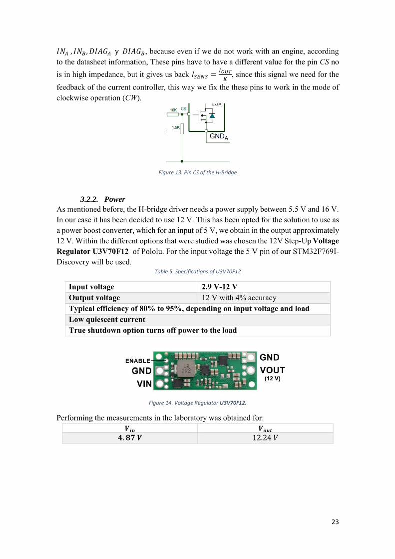
As mentioned before, the H-bridge driver needs a power supply between 5.5 V and 16 V. In our case it has been decided to use 12 V. This has been opted for the solution to use as a power boost converter, which for an input of 5 V, we obtain in the output approximately 12 V. Within the different options that were studied was chosen the 12V Step-Up Voltage Regulator U3V70F12 of Pololu. For the input voltage the 5 V pin of our STM32F769I-Discovery will be used.
Table 5. Specifications of U3V70F12
Input voltage 2.9 V-12 V Output voltage 12 V with 4% accuracy Typical efficiency of 80% to 95%, depending on input voltage and load Low quiescent current True shutdown option turns off power to the load
Figure 14. Voltage Regulator U3V70F12.
Performing the measurements in the laboratory was obtained for: 𝑽𝒊𝒏 𝑽𝒐𝒖𝒕
𝟒. 𝟖𝟕 𝑽 12.24 𝑉

24
4. Analog to Digital Converter To be able to work with the discrete PI controller, our input is required to be discrete signals. Since the "CS" pin on the H-Bridge is being read, the analogue signal must be converted to a digital signal. To do this, a digital analog converter is used. The conversion process consists of two parts, the first is the retention and sampling which implies that for each sampling time, the input signal is sampled and that value that has been sampled remains constant until the next sampling. The second is quantification and digitization, once we have the sample is selected at level of quantization, the nearest value, from this is given a binary code that will be used for our discrete or digital control-ler [10].
Figure 15. ADC behavior [18]
The microcontroller has 3 ADCs With 12 channels, we can work with them either by polling, interruption or if we want to leave the Loop Main, by DMA. For this system all three ways were tested, first tested independently and the most intuitive and simple was by interruption, but when tested throughout the block had problems with the operating system and activation by interruption of ADC. So it was decided to make a special thread to use the polling method. The number of bits can be decided between 12 to 6 bits. In order to have no conflicts with the ADC sampling and the operating system, 8 bits were chosen, so we will have 255 samples of the input signal.
25
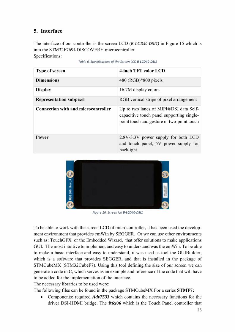
5. Interface The interface of our controller is the screen LCD (B-LCD40-DSI1) in Figure 15 which is into the STM32F769I-DISCOVERY microcontroller. Specifications:
Table 6. Specifications of the Screen LCD B-LCD40-DSI1
Type of screen 4-inch TFT color LCD
Dimensions 480 (RGB)*800 pixels
Display 16.7M display colors
Representation subpixel RGB vertical stripe of pixel arrangement
Connection with and microcontroller Up to two lanes of MIPI®DSI data Self-capacitive touch panel supporting single-point touch and gesture or two-point touch
Power 2.8V-3.3V power supply for both LCD and touch panel, 5V power supply for backlight
Figure 16. Screen lcd B-LCD40-DSI1
To be able to work with the screen LCD of microcontroller, it has been used the develop-ment environment that provides emWin by SEGGER. Or we can use other environments such as: TouchGFX or the Embedded Wizard, that offer solutions to make applications GUI. The most intuitive to implement and easy to understand was the emWin. To be able to make a basic interface and easy to understand, it was used as tool the GUIBuilder, which is a software that provides SEGGER, and that is installed in the package of STMCubeMX (STM32CubeF7). Using this tool defining the size of our screen we can generate a code in C, which serves as an example and reference of the code that will have to be added for the implementation of the interface. The necessary libraries to be used were: The following files can be found in the package STMCubeMX For a series STMF7:
• Components: required Adv7533 which contains the necessary functions for the driver DSI-HDMI bridge. The ft6x06 which is the Touch Panel controller that
26
connects to the microcontroller. And also the otm8009a, which contains the func-tions to control the screen.
• Necessary drivers BSP of the Microcontroller STM32F769I_DISCO: stm32f769i_discovery.c, stm32f769i_discovery_lcd.c, stm32f769i_discov-ery_sdram.c y stm32f769i_discovery_ts.c
By using KEIL, the following files could also be used: • On the part of Board Support Of Manage Run time Enviroment", the
Touch_769I_Discovery. c files were obtained, which contains functions neces-sary to initialize the touch screen.
The Files of emWin is: • GuiCONF, where the number of bytes available to the GUI is set, also needed
GUI_X_TOCUH . And on the other hand is the file, LCDconf that provides the emWin the display settings and callback functions for the controller [11].
To keep the screen in operation, we need an operating system, in our case we used the RTX5 which corresponds to the version (v2) of the operating systems of CMSIS KEIL. Although we tried to use version 1 of the operating system, we can also use FREERTOS. It is decided by the RTX5 because it can be configured with KEIL, it creates a thread that is responsible for launching the screen, before this we have to take into account the correct initialization, As previously discussed using the tool GUIBilder, a startup code was obtained to imple-ment the interface on the screen. The code where it is focused on the threads and the characteristics of the screen is found in the file lcd_App. In the thread corresponding to the screen are configured the different pages that are needed according to the functions that were generated with the tool emWin, the main loop runs the functions GUI_Exec() And GUI_TOUCH_Exec().

27
6. Microcontroller The microcontroller board is STM32F769I-DISCOVERY. It belongs to the series of the STM32F7, with a core cortex M-7.
Figure 17. STM32F69I-DISCOVERY Microcontroller
The most important features of the microcontroller are the I2C protocols (4), SPIs (6), UARTs(4), USARTs(4). There are also 3 ADCs 12-bit Max, two DACs 12-bit, too. It is important to underline that it has a flash memory of 2Mbyte, a SRAM 512 + 4 Kbyte. Flash Memory Quad-512 Mbit SPI. It has a MicroSD connector, connector Son Wi-Fi, Ethernet compatible with IEEE-802.3-2002 protocol, stereo speaker outputs, two pushbuttons (one for user and another for reset).We can add accessories like the LCD display B-LCD40-DSI1, external adaptor Wi-Fi ESP-01, DSI to HDMI adapter B-LCDAD-HDMI1 and a 15-pin DSI Adapter B-LCDAD-RPI1. It has five ways to feed, which one it has been used is via the USB HS connector. In the place of of a group of pins (CN3) that allow us to choose which interests us the most, so if we want to use it power cable USB stlk (Figure 9).
Figure 18. CN3 Pin to set the microcontroller's power mode.
28
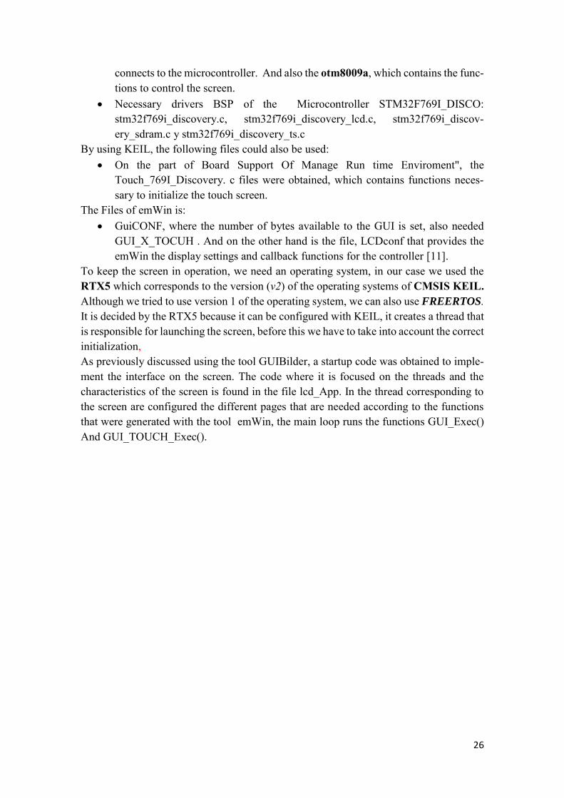
7. Development tools To work with the microcontroller we have different options as soon as the development environment. We can choose between Ewarm, GCC, ARM mbed online and KEIL MDK-ARM. First, it was tested third option but because it works with a powerful microcontroller, it would be a little bit scarce to implement the code in this environment. So it is decided at the end to do it in KEIL. This development environment is very powerful in addition to being recommended by the manufacturer of STM32. We can use the debugger, view the state of the peripherals, it contains Logic analyzer, RTOS window, etc. Along with KEIL, the free software provided by STM to its users has been used STM32Cube. With this tool the initialization of the elements used as timers, generate PWM signal, and others to use the HAL libraries. The code is in C, so it was easier to integrate the code for the interface because emWin uses code C. It is very practical and intuitive. Several photo captures are included to show how the KEIL is configured so that we can compile the code for this project.
Figure 19. Configuration of the card, aspects like range memory, generation of the code.
29
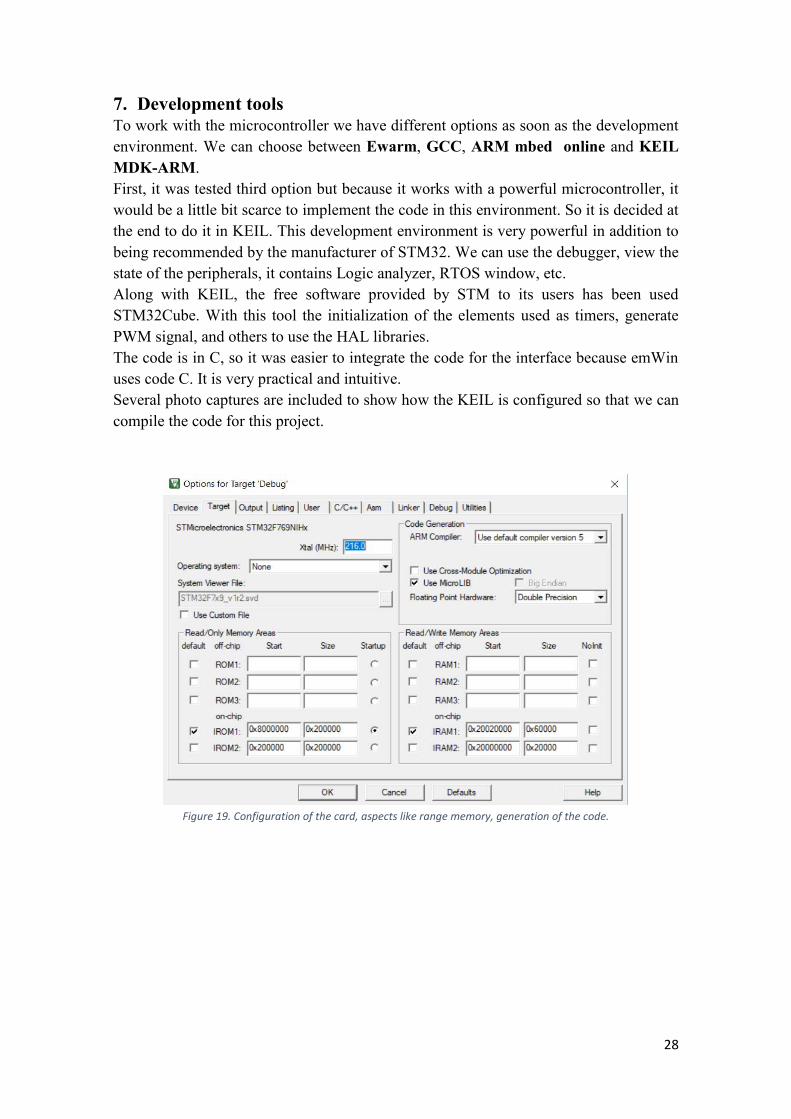
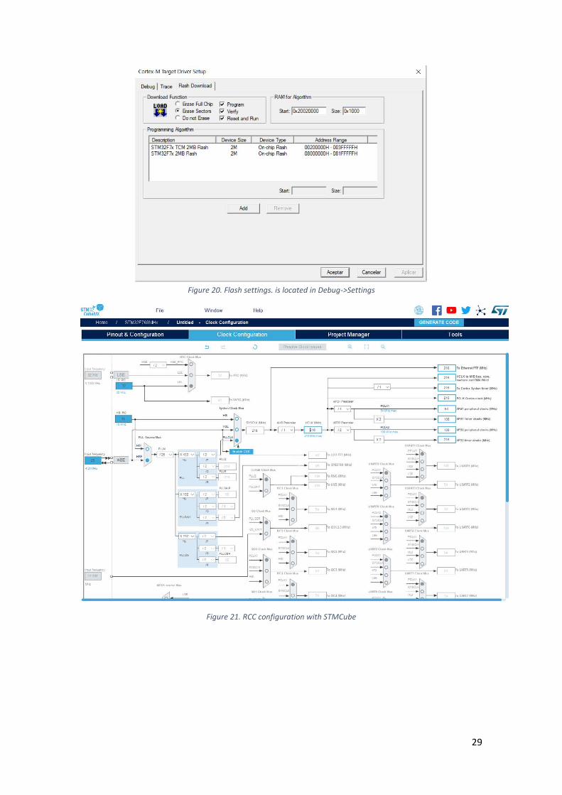
Figure 20. Flash settings. is located in Debug->Settings
Figure 21. RCC configuration with STMCube

30
8. Shock Absorber MR
Figure 22. MR Shock absorber.
These shock absorbers are used to improve the vibrations of different applications such as seismic shocks, aerial and terrestrial vehicles, seats, impact or energy absorbers [14] thanks to it is dynamic features such as quick response, power capacity and low battery consumption. Magneto-Rheological Shock absorbers use a liquid containing iron particles which when they come into contact with a magnetic field that is created from the electric current that runs through the internal piston coil, the changes it suffers the magnetic field causes the fluid to change becoming semisolid, that change that it experiences changing to this state allows to know the strength of the magnetic field. So the shock absorber can be controlled within the limits of the current by the coil [1]. The shock absorber is made up of different elements as seen in Figure 21, But mainly the idea is that it consists of a tube filled with this intelligent liquid and a piston that can move inside the tube. Inside the MR shocks There are different specimens like: Mono tube, Twin tube, Double ended MR damper, MR-Hydraulic hybrid damper. In our case as also seen in Figure 22, shows exemplary monotube MR damper for a vehicle.
31
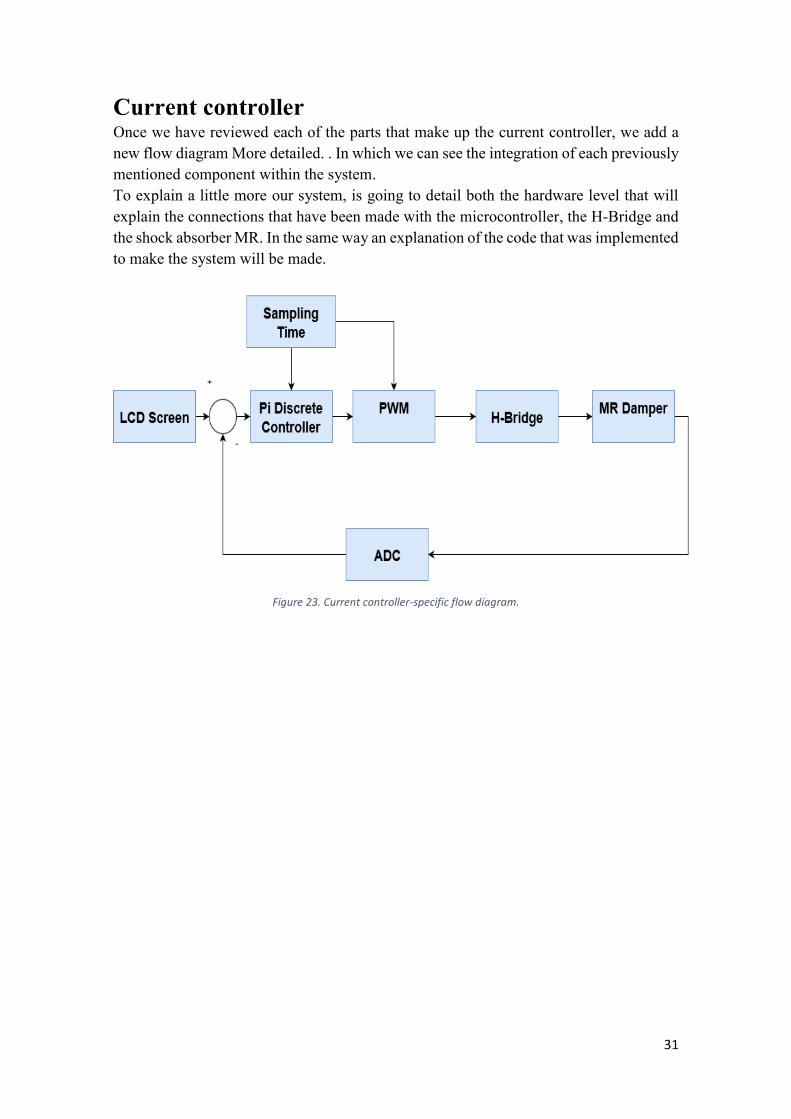
Current controller Once we have reviewed each of the parts that make up the current controller, we add a new flow diagram More detailed. . In which we can see the integration of each previously mentioned component within the system. To explain a little more our system, is going to detail both the hardware level that will explain the connections that have been made with the microcontroller, the H-Bridge and the shock absorber MR. In the same way an explanation of the code that was implemented to make the system will be made.
Figure 23. Current controller-specific flow diagram.

32
1. Hardware Most of the controller's work is developed with the microcontroller STM32F769I-DIS-COVERY. Therefore we are going to begin to describe which were the most important hardware resources.
Table 7. Pin layout in microcontroller [Annex 1, 2]
Microcontroller PWM PA11 CN9 ADC PC2
CN14 INA PF8 INB PF9 DIGA/ENA PC6
CN13 DIGB/ENB PC7 VIN 5V
CN11 GND GND
Table 8. Power connection for H-Bridge
H-Bridge power supply U3V70F12 Microcontroller Wine 5V GND GND
Table 9. H-Bridge Connection
H-Bridge INA PF8 DIAGA/ENA PC6 PWM PA11 CS PC2 DIAGB/ENB PC7 INB PF9 5V (IN) VIN GND GND OUTA +DAMPER OUTB DAMPER
33
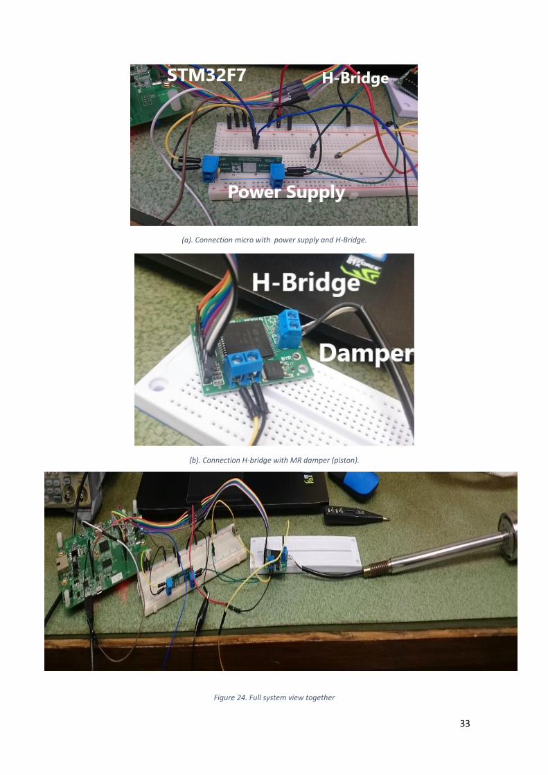
(a). Connection micro with power supply and H-Bridge.
(b). Connection H-bridge with MR damper (piston).
Figure 24. Full system view together

34
Figure 25. Sample of the signals in the case of chirp excitation
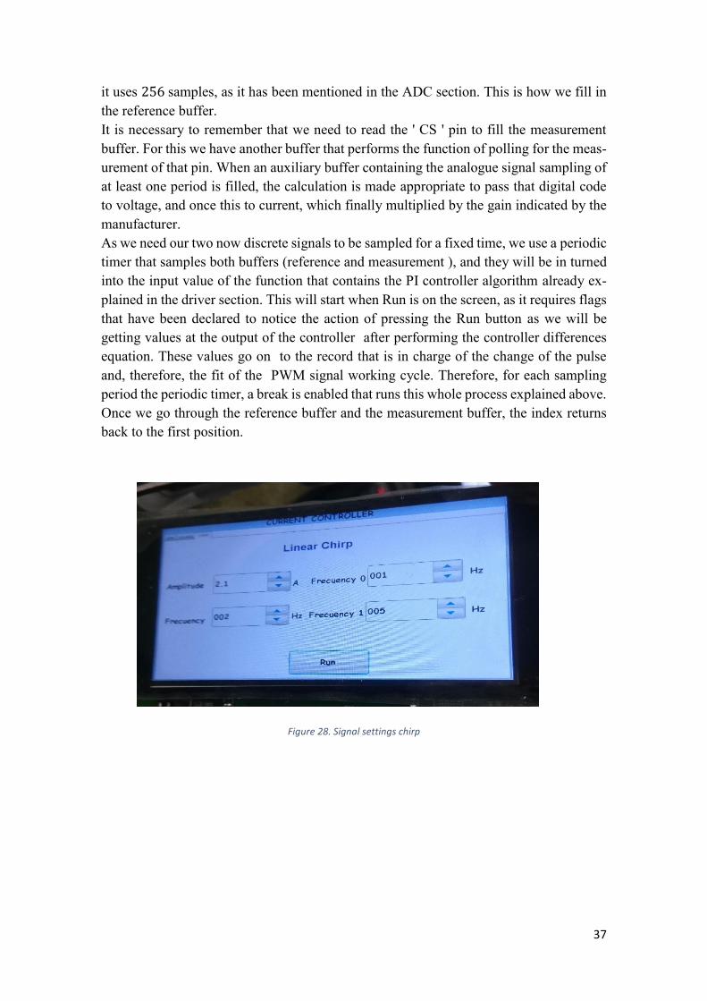
In Figure 25 in Channel 2 we can see the PWM signal at the input and Channel 1 the signal that is supplied to the piston. A linear signal is being applied chirp which is defined by the parameters in Figure 28.
Figure 26. Signals in the case of the sine signal excitation
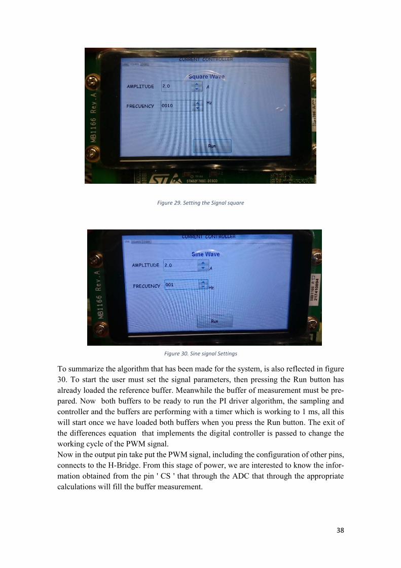
In Figure 26 in Channel 2 we can see, the PWM signal at the input and Channel 1 the signal that can be seen on the piston. A square signal is being applied according the pa-rameters in Figure 29.
35
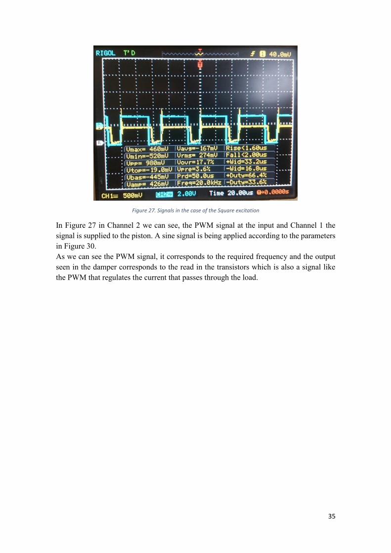
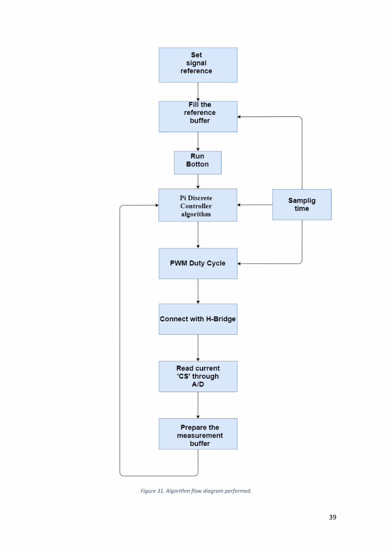
Figure 27. Signals in the case of the Square excitation
In Figure 27 in Channel 2 we can see, the PWM signal at the input and Channel 1 the signal is supplied to the piston. A sine signal is being applied according to the parameters in Figure 30. As we can see the PWM signal, it corresponds to the required frequency and the output seen in the damper corresponds to the read in the transistors which is also a signal like the PWM that regulates the current that passes through the load.
36
2. Software The code consists of Files.h and files.c for ADC, PWM, LCD display, signal generation, PI controller and periodic timer. These incorporate the declaration of variables and nec-essary functions for the task of each component and the source file where we incorporate the body of the functions according to the appropriate type. In the main file the main, all elements are initialized: MPU, HAL libraries, setting the System Clock, SDRAM, LCD, Touch Screen, ADC, pins and operating system. The MPU configuration is performed to determine the parameters that the SDRAM will have [12] for the system to be more robust and no problems occur in memory regions as regions overlap. The base address is marked in 0x20000000, and it has been given the size of 𝑀𝑃𝑈_𝑅𝐸𝐺𝐼𝑂𝑁_𝑆𝐼𝑍𝐸_512𝑀𝐵. The SDRAM is used to be able to easily make graphical application using the LCD Module, because it is connected to the internal RAM using the FMC, a controller which offers four independent banks to support external memory [12]. The initialization of HAL libraries configures the systick to be generated every 1 ms, also to a Real-time Adaptive memory accelerator (ART) [13]. On the other hand, the system clock to make it 216 𝑀𝐻𝑧 for this purpose, HSE is used as a PLL source from the crystal/ceramic resonator. As a source of systick the PLLCLK is use of, this way we can get the 216 𝑀𝐻𝑧 and the appropriate values for the watches of the peripheral figure 21. The screen configuration initializes the SDRAM, also the initialization of the Touchscreen, we need to define the size of the screen, in our case it is 800𝑥480. The macros are used for CRC and SRAM; Then initialized the GUI for graphic components. Then we set the logical value of the pins that are connected to the H-bridge, the timers that configures the PWM, the periodic timers, and the ADC. To end the initial operating system, we create the necessary threads, and to finish it runs. The operating system RTX5 uses threads to program the screen and for the operation of the ADC. For the screen it is necessary to first declare. To start the screen we need to declare an initial frame where we will be storing the different pages that contain the in-formation to adjust the signals using the function 𝐹𝑅𝐴𝑀𝐸𝑊𝐼𝑁_𝐶𝑟𝑒𝑎𝑡𝑒. Now it is possi-ble add the pages, in this case are 3 (sine, square and linear chirp). Each page contains enough parameters to adjust the signal, such as amplitude, frequency, etc. To do this it is necessary to use a struct that emWin calls dialogs, where the GUI resources we want to use are declared, each element declares the type, name, identifier, starting point, and so on. But before in the thread we will have to initialize the resource Multipages. Once this is done we can add the page with its corresponding dialogue and its corresponding func-tion that is responsible for editing aspects of the resources declared in the dialogue. For signal generation e have the file waveGenerator.c, where we have 3 functions with which we can generate the signals (sine, square and linear chirp). The library has been used for this purpose is math.h. The LCD screen allows the user to adjust the parameters for each signal. This information is edited by a spinbox, which for example in the case of amplitude is a value float to be able to have a higher range when setting that parameter. Once the signal is set. Remembering what was said in the previous section, each page of the display has different resources of the GUI. One of them is the Run button. When this is pressed once the values of the signal have been defined, the desired signal is generated,
37
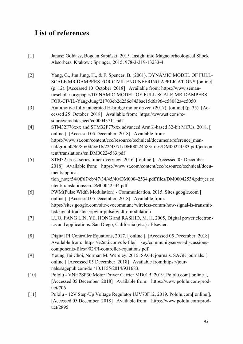
it uses 256 samples, as it has been mentioned in the ADC section. This is how we fill in the reference buffer. It is necessary to remember that we need to read the ' CS ' pin to fill the measurement buffer. For this we have another buffer that performs the function of polling for the meas-urement of that pin. When an auxiliary buffer containing the analogue signal sampling of at least one period is filled, the calculation is made appropriate to pass that digital code to voltage, and once this to current, which finally multiplied by the gain indicated by the manufacturer. As we need our two now discrete signals to be sampled for a fixed time, we use a periodic timer that samples both buffers (reference and measurement ), and they will be in turned into the input value of the function that contains the PI controller algorithm already ex-plained in the driver section. This will start when Run is on the screen, as it requires flags that have been declared to notice the action of pressing the Run button as we will be getting values at the output of the controller after performing the controller differences equation. These values go on to the record that is in charge of the change of the pulse and, therefore, the fit of the PWM signal working cycle. Therefore, for each sampling period the periodic timer, a break is enabled that runs this whole process explained above. Once we go through the reference buffer and the measurement buffer, the index returns back to the first position.
Figure 28. Signal settings chirp
38
Figure 29. Setting the Signal square
Figure 30. Sine signal Settings
To summarize the algorithm that has been made for the system, is also reflected in figure 30. To start the user must set the signal parameters, then pressing the Run button has already loaded the reference buffer. Meanwhile the buffer of measurement must be pre-pared. Now both buffers to be ready to run the PI driver algorithm, the sampling and controller and the buffers are performing with a timer which is working to 1 ms, all this will start once we have loaded both buffers when you press the Run button. The exit of the differences equation that implements the digital controller is passed to change the working cycle of the PWM signal. Now in the output pin take put the PWM signal, including the configuration of other pins, connects to the H-Bridge. From this stage of power, we are interested to know the infor-mation obtained from the pin ' CS ' that through the ADC that through the appropriate calculations will fill the buffer measurement.
39
Figure 31. Algorithm flow diagram performed.

40
Budget The budget that has been needed for this project has been:
Table 10. Budget
Electrical Device Price (PLN)
Voltage Regulator U3V70F12 39.90
VNH2SP30 Motor Driver Carrier MD01B
132,65
STM32F769I-DISCOVERY 225,31
Cables 11
Total 397.86
The convertion from PLN to Euros is 1 PLN equals 0.23 €. So the total price of the devices used is 91.51€. The hand work, taking into account that the monthly salary of a newly qualified engineer is 700€. Since the final project is 12 credits, each credit is equivalent to 26 or 27 hours so in total, then the estimated total hours will be 324 hours. Then, it is 1620€.

41
Conclusions The problem that had been posed has to develop a controller for an automotive shock absorber. The solution that was proposed was to do it using a 32-bit microcontroller, with a discrete PI controller, and electrical circuit with the piston power stage that supplies the current that passes through the piston. The design of the current controller has been implemented successfully, for the most part of the project there have been some errors reading signals from the H-Bridge. But, in general terms, future improvements can be continued with this line of research to expand the study of the absorber integrating more factors such as force, speed. Doing a complete study with a shaker. To finish with the implementation of the current controller it has been seen that it needs some improvements. For example the periodic timer that is activated by interruption would be much more useful to make the periodic interruption occurring when the ADC notice a signals change. It would also be interesting to try another external ADC that is bipolar. It would also be interesting that in addition to the interface offered by the display, the settings could be modified by means of the computer.
42
List of references
[1] Janusz Gołdasz, Bogdan Sapiński. 2015. Insight into Magnetorheological Shock Absorbers. Krakow : Springer, 2015. 978-3-319-13233-4.
[2] Yang, G., Jun Jung, H., & F. Spencer, B. (2001). DYNAMIC MODEL OF FULL-SCALE MR DAMPERS FOR CIVIL ENGINEERING APPLICATIONS [online] (p. 12). [Accessed 10 October 2018] Available from: https://www.seman-ticscholar.org/paper/DYNAMIC-MODEL-OF-FULL-SCALE-MR-DAMPERS-FOR-CIVIL-Yang-Jung/21703eb2d256c843bac15d6a964c58082a4c5050
[3] Automotive fully integrated H-bridge motor driver. (2017). [online] (p. 35). [Ac-cessed 25 October 2018] Available from: https://www.st.com/re-source/en/datasheet/cd00043711.pdf
[4] STM32F76xxx and STM32F77xxx advanced Arm®-based 32-bit MCUs, 2018. [ online ], [Accessed 05 December 2018] Available from: https://www.st.com/content/ccc/resource/technical/document/reference_man-ual/group0/96/8b/0d/ec/16/22/43/71/DM00224583/files/DM00224583.pdf/jcr:con-tent/translations/en.DM00224583.pdf
[5] STM32 cross-series timer overview, 2016. [ online ], [Accessed 05 December 2018] Available from: https://www.st.com/content/ccc/resource/technical/docu-ment/applica-tion_note/54/0f/67/eb/47/34/45/40/DM00042534.pdf/files/DM00042534.pdf/jcr:content/translations/en.DM00042534.pdf
[6] PWM(Pulse Width Modulation) - Communication, 2015. Sites.google.com [ online ], [Accessed 05 December 2018] Available from: https://sites.google.com/site/evocommune/wireless-comm/how-signal-is-transmit-ted/signal-transfer-3/pwm-pulse-width-modulation
[7] LUO, FANG LIN, YE, HONG and RASHID, M. H, 2005, Digital power electron-ics and applications. San Diego, California (etc.) : Elsevier.
[8] Digital PI Controller Equations, 2017. [ online ], [Accessed 05 December 2018] Available from: https://e2e.ti.com/cfs-file/__key/communityserver-discussions-components-files/902/PI-controller-equations.pdf
[9] Young Tai Choi, Norman M. Wereley. 2015. SAGE journals. SAGE journals. [ online ] [Accessed 05 December 2018] Available from:https://jour-nals.sagepub.com/doi/10.1155/2014/931683.
[10] Pololu - VNH2SP30 Motor Driver Carrier MD01B, 2019. Pololu.com[ online ], [Accessed 05 December 2018] Available from: https://www.pololu.com/prod-uct/706
[11] Pololu - 12V Step-Up Voltage Regulator U3V70F12, 2019. Pololu.com[ online ], [Accessed 05 December 2018] Available from: https://www.pololu.com/prod-uct/2895
43
[12] Graphic Library with Graphical User Interface User & Reference Guide, 2017. [ online ], [Accessed 05 December 2018] Available from: https://www.seg-ger.com/downloads/emwin/UM03001_emWin_V544.pdf
[13] Managing memory protection unit (MPU) in STM32 MCUs,2018. Stmicroelec-tronics. [ online ], [Accessed 25 Octuber 2018] Available from: https://www.st.com/content/ccc/resource/technical/document/applica-tion_note/group0/bc/2d/f7/bd/fb/3f/48/47/DM00272912/files/DM00272912.pdf/jcr:content/translations/en.DM00272912.pdf
[14] STM32 Memory Flash Interface. Stmicroelectronics. [ online ], [Accessed 6 Octu-ber 2018] Available from: https://www.st.com/content/ccc/resource/train-ing/technical/product_train-ing/group0/62/e5/37/be/d5/31/4c/23/STM32F7_Memory_Flash/files/STM32F7_Memory_Flash.pdf/_jcr_content/translations/en.STM32F7_Memory_Flash.pdf
[15] UNIVERSITY, L. G. Digital Signal Processing. Retrieved from Digital Signal Processing.[ online ], [Accessed 18 January 2019] Available from: https://www.phon.ucl.ac.uk/courses/spsci/dsp/sample.html
[16] High gain single-stage inverter for photovoltaic AC modules,2011.[online].[Ac-cessed 14 Junary 2019] Available from: https://www.researchgate.net/publica-tion/234080597_High_gain_single-stage_inverter_for_photovoltaic_AC_modules
[17] Electrical Engineering,[online].[Accessed 01 January 2019] Available from: https://electronics.stackexchange.com/questions/207319/multiple-motor-h-bridge
[18] STM32F4: Configuración y uso básico del adc.2018.[online].[Accessed 01 De-cember 2019] Available from: http://elb105.com/stm32f4-configuracion-y-uso-basico-del-adc/
44
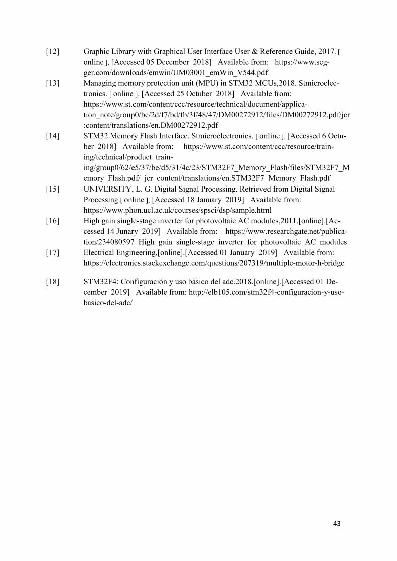
Annex Annex 1. STM32F769I-DISCOVERY CN11 and CN14 microcontroller con-nectors
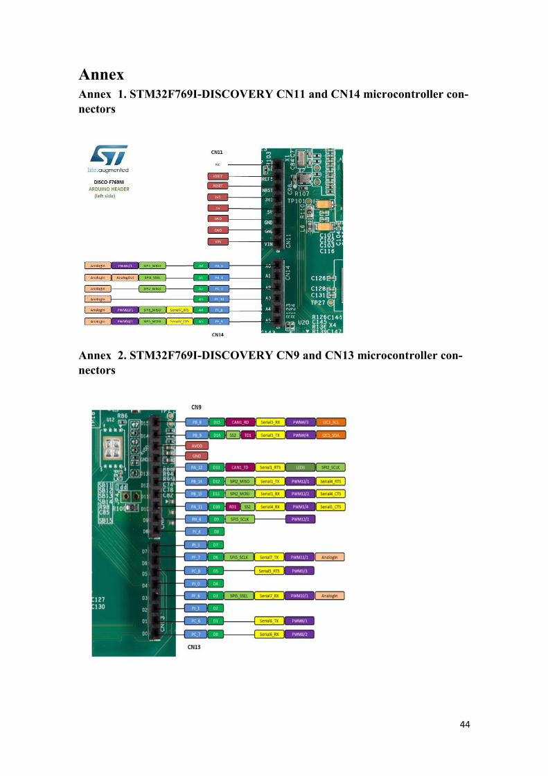
Annex 2. STM32F769I-DISCOVERY CN9 and CN13 microcontroller con-nectors
45
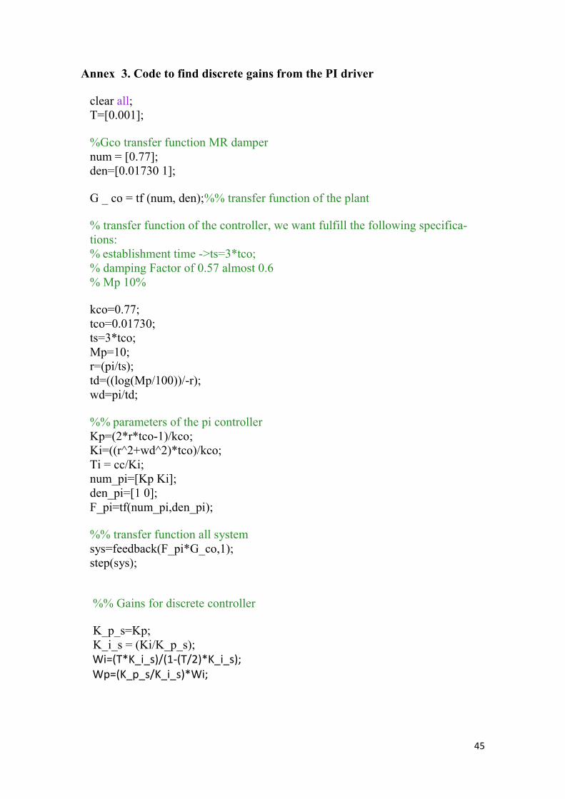
Annex 3. Code to find discrete gains from the PI driver
clear all; T=[0.001]; %Gco transfer function MR damper num = [0.77]; den=[0.01730 1]; G _ co = tf (num, den);%% transfer function of the plant % transfer function of the controller, we want fulfill the following specifica-tions: % establishment time ->ts=3*tco; % damping Factor of 0.57 almost 0.6 % Mp 10% kco=0.77; tco=0.01730; ts=3*tco; Mp=10; r=(pi/ts); td=((log(Mp/100))/-r); wd=pi/td; %% parameters of the pi controller Kp=(2*r*tco-1)/kco; Ki=((r^2+wd^2)*tco)/kco; Ti = cc/Ki; num_pi=[Kp Ki]; den_pi=[1 0]; F_pi=tf(num_pi,den_pi); %% transfer function all system sys=feedback(F_pi*G_co,1); step(sys); %% Gains for discrete controller K_p_s=Kp; K_i_s = (Ki/K_p_s); Wi=(T*K_i_s)/(1-(T/2)*K_i_s); Wp=(K_p_s/K_i_s)*Wi;
46
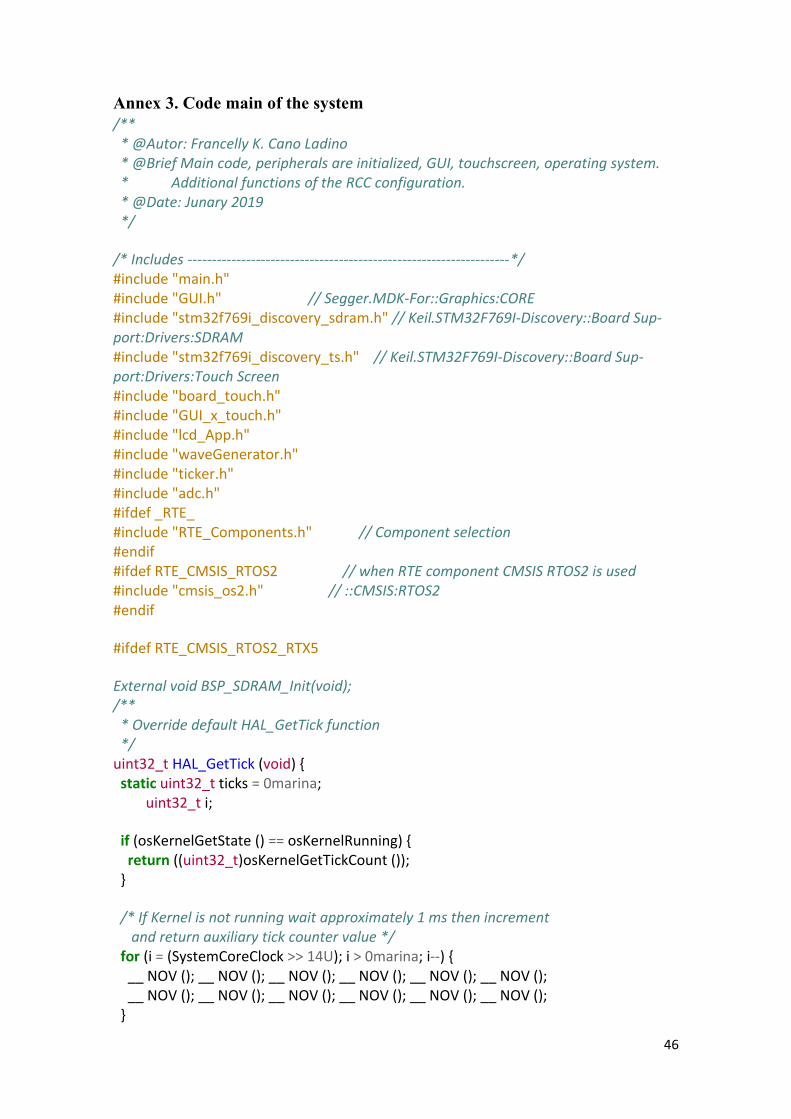
Annex 3. Code main of the system /** * @Autor: Francelly K. Cano Ladino * @Brief Main code, peripherals are initialized, GUI, touchscreen, operating system. * Additional functions of the RCC configuration. * @Date: Junary 2019 */ /* Includes ------------------------------------------------------------------*/ #include "main.h" #include "GUI.h" // Segger.MDK-For::Graphics:CORE #include "stm32f769i_discovery_sdram.h" // Keil.STM32F769I-Discovery::Board Sup-port:Drivers:SDRAM #include "stm32f769i_discovery_ts.h" // Keil.STM32F769I-Discovery::Board Sup-port:Drivers:Touch Screen #include "board_touch.h" #include "GUI_x_touch.h" #include "lcd_App.h" #include "waveGenerator.h" #include "ticker.h" #include "adc.h" #ifdef _RTE_ #include "RTE_Components.h" // Component selection #endif #ifdef RTE_CMSIS_RTOS2 // when RTE component CMSIS RTOS2 is used #include "cmsis_os2.h" // ::CMSIS:RTOS2 #endif #ifdef RTE_CMSIS_RTOS2_RTX5 External void BSP_SDRAM_Init(void); /** * Override default HAL_GetTick function */ uint32_t HAL_GetTick (void) static uint32_t ticks = 0marina; uint32_t i; if (osKernelGetState () == osKernelRunning) return ((uint32_t)osKernelGetTickCount ()); /* If Kernel is not running wait approximately 1 ms then increment and return auxiliary tick counter value */ for (i = (SystemCoreClock >> 14U); i > 0marina; i--) __ NOV (); __ NOV (); __ NOV (); __ NOV (); __ NOV (); __ NOV (); __ NOV (); __ NOV (); __ NOV (); __ NOV (); __ NOV (); __ NOV ();
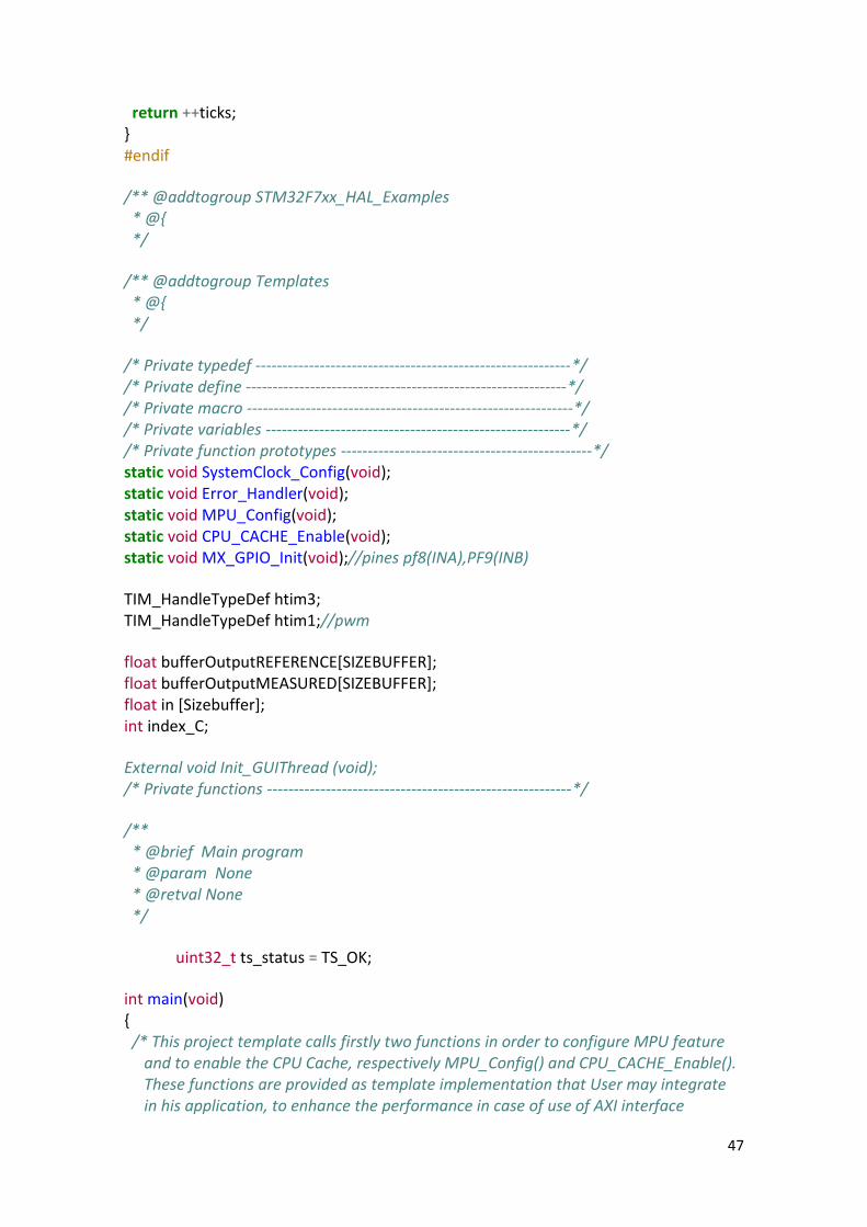
47
return ++ticks; #endif /** @addtogroup STM32F7xx_HAL_Examples * @ */ /** @addtogroup Templates * @ */ /* Private typedef -----------------------------------------------------------*/ /* Private define ------------------------------------------------------------*/ /* Private macro -------------------------------------------------------------*/ /* Private variables ---------------------------------------------------------*/ /* Private function prototypes -----------------------------------------------*/ static void SystemClock_Config(void); static void Error_Handler(void); static void MPU_Config(void); static void CPU_CACHE_Enable(void); static void MX_GPIO_Init(void);//pines pf8(INA),PF9(INB) TIM_HandleTypeDef htim3; TIM_HandleTypeDef htim1;//pwm float bufferOutputREFERENCE[SIZEBUFFER]; float bufferOutputMEASURED[SIZEBUFFER]; float in [Sizebuffer]; int index_C; External void Init_GUIThread (void); /* Private functions ---------------------------------------------------------*/ /** * @brief Main program * @param None * @retval None */ uint32_t ts_status = TS_OK; int main(void) /* This project template calls firstly two functions in order to configure MPU feature and to enable the CPU Cache, respectively MPU_Config() and CPU_CACHE_Enable(). These functions are provided as template implementation that User may integrate in his application, to enhance the performance in case of use of AXI interface
48
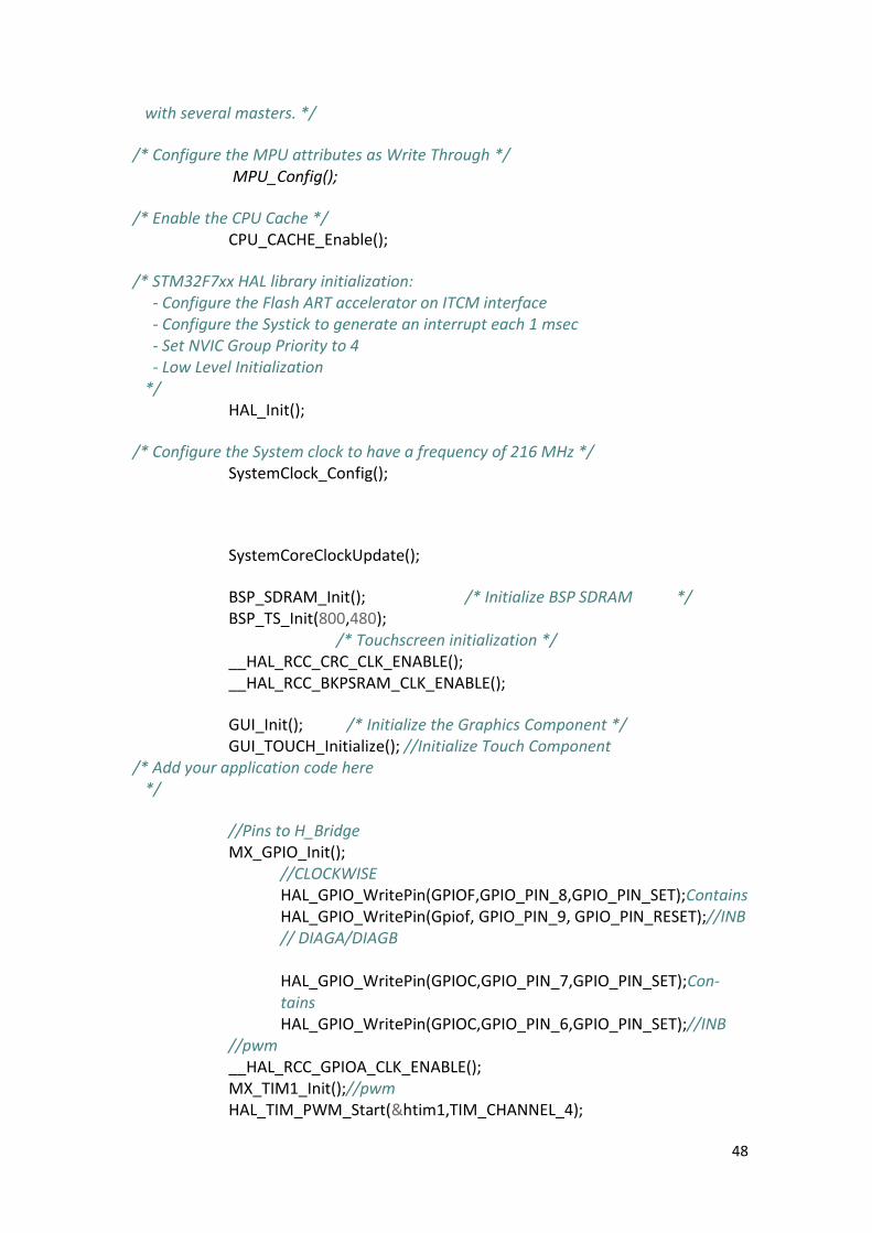
with several masters. */ /* Configure the MPU attributes as Write Through */ MPU_Config(); /* Enable the CPU Cache */ CPU_CACHE_Enable(); /* STM32F7xx HAL library initialization: - Configure the Flash ART accelerator on ITCM interface - Configure the Systick to generate an interrupt each 1 msec - Set NVIC Group Priority to 4 - Low Level Initialization */ HAL_Init(); /* Configure the System clock to have a frequency of 216 MHz */ SystemClock_Config(); SystemCoreClockUpdate(); BSP_SDRAM_Init(); /* Initialize BSP SDRAM */ BSP_TS_Init(800,480); /* Touchscreen initialization */ __HAL_RCC_CRC_CLK_ENABLE(); __HAL_RCC_BKPSRAM_CLK_ENABLE(); GUI_Init(); /* Initialize the Graphics Component */ GUI_TOUCH_Initialize(); //Initialize Touch Component /* Add your application code here */ //Pins to H_Bridge MX_GPIO_Init(); //CLOCKWISE HAL_GPIO_WritePin(GPIOF,GPIO_PIN_8,GPIO_PIN_SET);Contains HAL_GPIO_WritePin(Gpiof, GPIO_PIN_9, GPIO_PIN_RESET);//INB // DIAGA/DIAGB
HAL_GPIO_WritePin(GPIOC,GPIO_PIN_7,GPIO_PIN_SET);Con-tains
HAL_GPIO_WritePin(GPIOC,GPIO_PIN_6,GPIO_PIN_SET);//INB //pwm __HAL_RCC_GPIOA_CLK_ENABLE(); MX_TIM1_Init();//pwm HAL_TIM_PWM_Start(&htim1,TIM_CHANNEL_4);
49
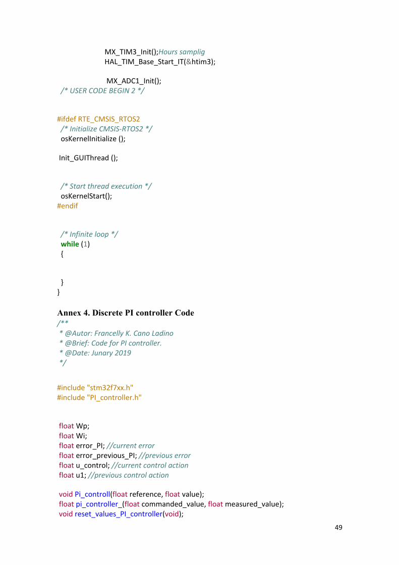
MX_TIM3_Init();Hours samplig HAL_TIM_Base_Start_IT(&htim3); MX_ADC1_Init(); /* USER CODE BEGIN 2 */ #ifdef RTE_CMSIS_RTOS2 /* Initialize CMSIS-RTOS2 */ osKernelInitialize (); Init_GUIThread (); /* Start thread execution */ osKernelStart(); #endif /* Infinite loop */ while (1) Annex 4. Discrete PI controller Code /** * @Autor: Francelly K. Cano Ladino * @Brief: Code for PI controller. * @Date: Junary 2019 */
#include "stm32f7xx.h" #include "PI_controller.h" float Wp; float Wi; float error_PI; //current error float error_previous_PI; //previous error float u_control; //current control action float u1; //previous control action void Pi_controll(float reference, float value); float pi_controller_(float commanded_value, float measured_value); void reset_values_PI_controller(void);

50
float pi_controller_(float commanded_value, float measured_value) We assign discrete earnings values Wp=WP_DISCRETE; Wi=WI_DISCRETE; Driver input failed error_PI=commanded_value-measured_value; //Control ecuation u_control=u1+(Wp*(1+Wi))*error_PI-Wp*error_previous_PI; //Controller: Clamping Ecstatic of the Integrator (Anti-windup) // if((u_control>=I_MAX_LIMIT)&&(u_control<=I_MIN_LIMIT)) // error_previous_PI=error_PI; // //Output Saturation if (u_control >= 1) u_control=0; else if (u_control <= 0) u_control=0; We leave prepared next interaction
//Update the control variable and error variable for the next sampling period u1=u_control; error_previous_PI=error_PI; return(u_control);
51
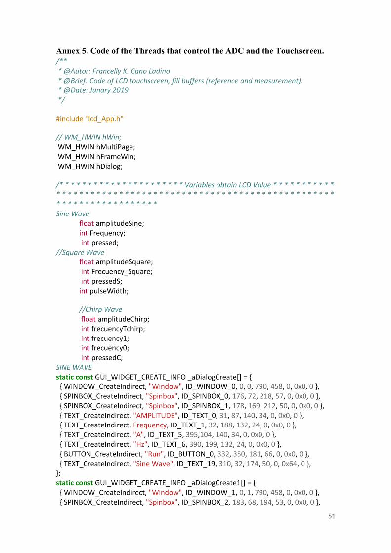
Annex 5. Code of the Threads that control the ADC and the Touchscreen. /** * @Autor: Francelly K. Cano Ladino * @Brief: Code of LCD touchscreen, fill buffers (reference and measurement). * @Date: Junary 2019 */ #include "lcd_App.h" // WM_HWIN hWin; WM_HWIN hMultiPage; WM_HWIN hFrameWin; WM_HWIN hDialog; /* * * * * * * * * * * * * * * * * * * * * * Variables obtain LCD Value * * * * * * * * * * * * * * * * * * * * * * * * * * * * * * * * * * * * * * * * * * * * * * * * * * * * * * * * * * * * * * * * * * * * * * * * * * * * * * Sine Wave float amplitudeSine; int Frequency; int pressed; //Square Wave float amplitudeSquare; int Frecuency_Square; int pressedS; int pulseWidth; //Chirp Wave float amplitudeChirp; int frecuencyTchirp; int frecuency1; int frecuency0; int pressedC; SINE WAVE static const GUI_WIDGET_CREATE_INFO _aDialogCreate[] = WINDOW_CreateIndirect, "Window", ID_WINDOW_0, 0, 0, 790, 458, 0, 0x0, 0 , SPINBOX_CreateIndirect, "Spinbox", ID_SPINBOX_0, 176, 72, 218, 57, 0, 0x0, 0 , SPINBOX_CreateIndirect, "Spinbox", ID_SPINBOX_1, 178, 169, 212, 50, 0, 0x0, 0 , TEXT_CreateIndirect, "AMPLITUDE", ID_TEXT_0, 31, 87, 140, 34, 0, 0x0, 0 , TEXT_CreateIndirect, Frequency, ID_TEXT_1, 32, 188, 132, 24, 0, 0x0, 0 , TEXT_CreateIndirect, "A", ID_TEXT_5, 395,104, 140, 34, 0, 0x0, 0 , TEXT_CreateIndirect, "Hz", ID_TEXT_6, 390, 199, 132, 24, 0, 0x0, 0 , BUTTON_CreateIndirect, "Run", ID_BUTTON_0, 332, 350, 181, 66, 0, 0x0, 0 , TEXT_CreateIndirect, "Sine Wave", ID_TEXT_19, 310, 32, 174, 50, 0, 0x64, 0 , ; static const GUI_WIDGET_CREATE_INFO _aDialogCreate1[] = WINDOW_CreateIndirect, "Window", ID_WINDOW_1, 0, 1, 790, 458, 0, 0x0, 0 , SPINBOX_CreateIndirect, "Spinbox", ID_SPINBOX_2, 183, 68, 194, 53, 0, 0x0, 0 ,
52
SPINBOX_CreateIndirect, "Spinbox", ID_SPINBOX_3, 180, 161, 201, 54, 0, 0x0, 0 , // SPINBOX_CreateIndirect, "Spinbox", ID_SPINBOX_4, 181, 243, 195, 56, 0, 0x0, 0 , TEXT_CreateIndirect, "AMPLITUDE", ID_TEXT_2, 23, 85, 145, 30, 0, 0x0, 0 , TEXT_CreateIndirect, Frequency, ID_TEXT_3, 23, 179, 145, 20, 0, 0x0, 0 , // TEXT_CreateIndirect, "DUTY CYCLE", ID_TEXT_4, 14, 260, 161, 33, 0, 0x0, 0 , TEXT_CreateIndirect, "A", ID_TEXT_7, 395, 85, 145, 30, 0, 0x0, 0 , TEXT_CreateIndirect, "Hz", ID_TEXT_8, 395, 161, 80, 20, 0, 0x0, 0 , // TEXT_CreateIndirect, "%", ID_TEXT_9, 395, 260, 161, 33, 0, 0x0, 0 , BUTTON_CreateIndirect, "Run", ID_BUTTON_1, 332, 350, 181,66, 0, 0x0, 0 , TEXT_CreateIndirect, "Square Wave", ID_TEXT_20, 310, 32, 174, 50, 0, 0x64, 0 , ; static const GUI_WIDGET_CREATE_INFO _aDialogCreate2[] = WINDOW_CreateIndirect, "Window", ID_WINDOW_2, 0, 0, 800, 480, 0, 0x0, 0 , SPINBOX_CreateIndirect, "Spinbox", ID_SPINBOX_5, 138, 116, 193, 58, 0, 0x0, 0 , SPINBOX_CreateIndirect, "Spinbox", ID_SPINBOX_6, 139, 216, 190, 58, 0, 0x0, 0 , SPINBOX_CreateIndirect, "Spinbox", ID_SPINBOX_7, 508, 114, 197, 60, 0, 0x0, 0 , SPINBOX_CreateIndirect, "Spinbox", ID_SPINBOX_8, 504, 216, 205, 56, 0, 0x0, 0 , TEXT_CreateIndirect, "Linear Chirp", ID_TEXT_10, 310, 32, 174, 50, 0, 0x64, 0 , TEXT_CreateIndirect, "Amplitude", ID_TEXT_11, 15, 134, 107, 26, 0, 0x0, 0 , TEXT_CreateIndirect, "Frequency", ID_TEXT_12, 17, 241, 115, 34, 0, 0x0, 0 , TEXT_CreateIndirect, "Frequency 0", ID_TEXT_13, 379, 138, 127, 31, 0, 0x0, 0 , TEXT_CreateIndirect, "Frequency 1", ID_TEXT_14, 376, 236, 130, 31, 0, 0x0, 0 , TEXT_CreateIndirect, "A", ID_TEXT_15, 335, 140, 34, 26, 0, 0x0, 0 , TEXT_CreateIndirect, "Hz", ID_TEXT_16, 334, 237, 35, 33, 0, 0x0, 0 , TEXT_CreateIndirect, "Hz", ID_TEXT_17, 718, 135, 39, 30, 0, 0x0, 0 , TEXT_CreateIndirect, "Hz", ID_TEXT_18, 720, 237, 80, 20, 0, 0x0, 0 , BUTTON_CreateIndirect, "Run", ID_BUTTON_2, 332, 350, 181, 66, 0, 0x0, 0 , // USER START (Optionally insert additional widgets) // USER END ; /******************************** Thread **********************************************/ // Main stack size must be multiple of 8 Bytes uint64_t App _ main _ stk[APP _ MAIN _ STK _ SZ / 8]; const osThreadAttr_t app_main_attr = .stack_mem = &App _ main _ stk[0], .stack_size = sizeof(App _ main _ stk) ; const osThreadAttr_t thread_1_atrr; //Adc osThreadId_t adc_ID; osThreadId_t lcd_ID; osThreadId_t th1_ID; osEventFlagsId_t evt_id;
53
void Init_GUIThread (void) evt_id = osEventFlagsNew (NULL); /* Create application main thread */ lcd_ID=osThreadNew(app_main, NULL, NULL); //new th1_ID=osThreadNew (threadN1, NULL, NULL); adc_ID=osThreadNew(thread_ADC,NULL,NULL); //osThreadJoin(adc_ID); //ADC __NO_RETURN void thread_ADC (void *argument) (void)argument; HAL_ADC_Start(&hadc1); // osDelay(1); while(1) HAL_ADC_PollForConversion(&hadc1, 10000); bufferOut[indexADC]=HAL_ADC_GetValue(&hadc1); Send a signal to the other thread if((bufferOut[0]==0)&&((bufferOut[1]>=1)&&(bufferOut[1]<=4))) find=1; memcpy ( &bufferOutT, &bufferOut, sizeof(bufferOut) ); bufferADC[contP]=((((bufferOutT[contP]*3.3)/255)/1500)*11370); contP++; else //i=0; Signal to the thread adc indexADC++; if(indexADC>255) indexADC=0; // //osDelay(1); //End Adc

54
/***************************************************************************************/ static void _cbDialog(WM_MESSAGE * pMsg) WM_HWIN Hit; EDIT_Handle hEdit; int NCode; int Id; switch (pMsg->MsgId) case WM_INIT_DIALOG: // // Initialization of 'Spinbox AMPLITUDE' // Hit = WM_GetDialogItem(pMsg->hWin, ID_SPINBOX_0); hEdit = SPINBOX_GetEditHandle(Hit); EDIT_SetFloatMode ( hEdit , 0.5 , 0 , 5 , 1 , GUI_EDIT_NORMAL ); SPINBOX_SetFont(Hit, GUI_FONT_COMIC24B_1); // // Initialization of 'Spinbox Frequency // Hit = WM_GetDialogItem(pMsg->hWin, ID_SPINBOX_1); SPINBOX_SetRangeHit1,100); //SPINBOX_SetStep(hit, 10); SPINBOX_SetFont(Hit, GUI_FONT_COMIC24B_1); // // Initialization of 'AMPLITUDE' // Hit = WM_GetDialogItem(pMsg->hWin, ID_TEXT_0); TEXT_SetFont(Hit, GUI_FONT_COMIC24B_1); // // Initialization of 'FRECUENCY' // Hit = WM_GetDialogItem(pMsg->hWin, ID_TEXT_1); TEXT_SetFont(Hit, GUI_FONT_COMIC24B_1); // Initialization of 'V' // Hit = WM_GetDialogItem(pMsg->hWin, ID_TEXT_5); TEXT_SetFont(Hit, GUI_FONT_COMIC24B_1); // // Initialization of 'Hz' // Hit = WM_GetDialogItem(pMsg->hWin, ID_TEXT_6); TEXT_SetFont(Hit, GUI_FONT_COMIC24B_1);
55
// Initialization of 'Sine Wave' // Hit = WM_GetDialogItem(pMsg->hWin, ID_TEXT_19); TEXT_SetFont(Hit, GUI_FONT_32B_ASCII); TEXT_SetTextColor(Hit, GUI_MAKE_COLOR(0x00A00000)); // Initialization of 'Run' Hit = WM_GetDialogItem(pMsg->hWin, ID_BUTTON_0); BUTTON_SetFont(Hit, GUI_FONT_COMIC24B_1); break; case WM_NOTIFY_PARENT: Id = WM_GetId(pMsg->hWinSrc); NCode = pMsg->Data.v; switch(Id) case ID_SPINBOX_0: // Notifications sent by 'Spinbox' switch(NCode) case WM_NOTIFICATION_CLICKED: break; case WM_NOTIFICATION_RELEASED: break; case WM_NOTIFICATION_MOVED_OUT: break; case WM_NOTIFICATION_VALUE_CHANGED: amplitudeSine = SPINBOX_GetValue(pMsg->hWinSrc); break; break; case ID_SPINBOX_1: // Notifications sent by 'Spinbox' switch(NCode) case WM_NOTIFICATION_CLICKED: break; case WM_NOTIFICATION_RELEASED: break; case WM_NOTIFICATION_MOVED_OUT: break; case WM_NOTIFICATION_VALUE_CHANGED: Frequency=SPINBOX_GetValue(pMsg->hWinSrc); break; // USER START (Optionally insert additional code for further notification handling) // USER END
56
break; case ID_BUTTON_0: // Notifications sent by 'Spinbox' switch(NCode) case WM_NOTIFICATION_CLICKED: pressed=1;pressedS=0;pressedC=0; memset(bufferOutputREFERENCE,0,sizeof(bufferOutputREFERENCE)); for(int i=1;i<=WAVESIZE;i++)
bufferOutputREFERENCE[i] = Sample_SineWave(Frequency, Ampli-tudeSine/10,i/SAMPRATE);
//signal Of begin ADC // osThreadFlagsSet (th1_ID, 0x0001); break; case WM_NOTIFICATION_RELEASED: break; case WM_NOTIFICATION_MOVED_OUT: break; break; break; default: WM_DefaultProc(pMsg); break; static void _cbDialog1(WM_MESSAGE * pMsg) EDIT_Handle hEdit; WM_HWIN Hit; int NCode; int Id; // USER START (Optionally insert additional variables) // USER END switch (pMsg->MsgId) case WM_INIT_DIALOG: // // Initialization of 'Spinbox AMPLITUDE' // Hit = WM_GetDialogItem(pMsg->hWin, ID_SPINBOX_2); hEdit = SPINBOX_GetEditHandle(Hit); EDIT_SetFloatMode ( hEdit , 0.5 , 0 , 5 , 1 , GUI_EDIT_NORMAL ); SPINBOX_SetFont(Hit, GUI_FONT_COMIC24B_1);
57
// // Initialization of 'Spinbox period' // Hit = WM_GetDialogItem(pMsg->hWin, ID_SPINBOX_3); SPINBOX_SetStepHit10); SPINBOX_SetRangeHit10,1000); SPINBOX_SetFont(Hit, GUI_FONT_COMIC24B_1); // // Initialization of 'Spinbox' // // Hit = WM_GetDialogItem(pMsg->hWin, ID_SPINBOX_4); // SPINBOX_SetStep(hit, 10); // SPINBOX_SetFont(Hit, GUI_FONT_COMIC24B_1); // // Initialization of 'AMPLITUDE' // Hit = WM_GetDialogItem(pMsg->hWin, ID_TEXT_2); TEXT_SetFont(Hit, GUI_FONT_COMIC24B_1); // // Initialization of 'FRECUENCY' // Hit = WM_GetDialogItem(pMsg->hWin, ID_TEXT_3); TEXT_SetFont(Hit, GUI_FONT_COMIC24B_1); // // // Initialization of 'PULSE WIDTH' // // // Hit = WM_GetDialogItem(pMsg->hWin, ID_TEXT_4); // TEXT_SetFont(Hit, GUI_FONT_COMIC24B_1); // Initialization of 'V' // Hit = WM_GetDialogItem(pMsg->hWin, ID_TEXT_7); TEXT_SetFont(Hit, GUI_FONT_COMIC24B_1); // // Initialization of 'Hz' // Hit = WM_GetDialogItem(pMsg->hWin, ID_TEXT_8); TEXT_SetFont(Hit, GUI_FONT_COMIC24B_1); // // Initialization of '%' // Hit = WM_GetDialogItem(pMsg->hWin, ID_TEXT_9); TEXT_SetFont(Hit, GUI_FONT_COMIC24B_1); // Initialization of 'Square Wave' // Hit = WM_GetDialogItem(pMsg->hWin, ID_TEXT_20); TEXT_SetFont(Hit, GUI_FONT_32B_ASCII); TEXT_SetTextColor(Hit, GUI_MAKE_COLOR(0x00A00000));
58
// Initialization of 'Run' Hit = WM_GetDialogItem(pMsg->hWin, ID_BUTTON_1); BUTTON_SetFont(Hit, GUI_FONT_COMIC24B_1); break; case WM_NOTIFY_PARENT: Id = WM_GetId(pMsg->hWinSrc); NCode = pMsg->Data.v; switch(Id) case ID_SPINBOX_2: // Notifications sent by 'Spinbox' switch(NCode) case WM_NOTIFICATION_CLICKED: break; case WM_NOTIFICATION_RELEASED: break; case WM_NOTIFICATION_MOVED_OUT: break; case WM_NOTIFICATION_VALUE_CHANGED: amplitudeSquare=(float)SPINBOX_GetValue(pMsg->hWinSrc); break; break; case ID_SPINBOX_3: // Notifications sent by 'Spinbox' switch(NCode) case WM_NOTIFICATION_CLICKED: break; case WM_NOTIFICATION_RELEASED: break; case WM_NOTIFICATION_MOVED_OUT: break; case WM_NOTIFICATION_VALUE_CHANGED: Frecuency_Square=SPINBOX_GetValue(pMsg->hWinSrc); break; break; case ID_SPINBOX_4: // Notifications sent by 'Spinbox' switch(NCode) case WM_NOTIFICATION_CLICKED: break;

59
case WM_NOTIFICATION_RELEASED: break; case WM_NOTIFICATION_MOVED_OUT: break; case WM_NOTIFICATION_VALUE_CHANGED: pulseWidth=SPINBOX_GetValue(pMsg->hWinSrc); break; break; case ID_BUTTON_1: // Notifications sent by 'Spinbox' switch(NCode) case WM_NOTIFICATION_CLICKED: pressedS=1;pressed=0;pressedC=0; memset(bufferOutputREFERENCE,0,sizeof(bufferOutputREFER-ENCE)); Sample_SquareWave(amplitudeSquare/10, Frecuency_Square,256.0); break; case WM_NOTIFICATION_RELEASED: pressed=0; break; case WM_NOTIFICATION_MOVED_OUT: break; break; break; default: WM_DefaultProc(pMsg); break; //CHIRP static void _cbDialog2(WM_MESSAGE * pMsg) WM_HWIN Hit; EDIT_Handle hEdit; int NCode; int Id; // USER START (Optionally insert additional variables)
60
// USER END switch (pMsg->MsgId) case WM_INIT_DIALOG: // // Initialization of 'Window' // Hit = pMsg->hWin; WINDOW_SetBkColor(Hit, GUI_MAKE_COLOR(0x00FFFFFF)); // // Initialization of 'Spinbox' // Hit = WM_GetDialogItem(pMsg->hWin, ID_SPINBOX_5); hEdit = SPINBOX_GetEditHandle(Hit); EDIT_SetFloatMode ( hEdit , 0.5 , 0 , 5 , 1 , GUI_EDIT_NORMAL ); SPINBOX_SetFont(Hit, GUI_FONT_COMIC24B_1); // // Initialization of 'Spinbox' // Hit = WM_GetDialogItem(pMsg->hWin, ID_SPINBOX_6); SPINBOX_SetFont(Hit, GUI_FONT_COMIC24B_1); // // Initialization of 'Spinbox' // Hit = WM_GetDialogItem(pMsg->hWin, ID_SPINBOX_7); SPINBOX_SetFont(Hit, GUI_FONT_COMIC24B_1); // // Initialization of 'Spinbox' // Hit = WM_GetDialogItem(pMsg->hWin, ID_SPINBOX_8); SPINBOX_SetFont(Hit, GUI_FONT_COMIC24B_1); // // Initialization of 'Linear Chirp' // Hit = WM_GetDialogItem(pMsg->hWin, ID_TEXT_10); TEXT_SetFont(Hit, GUI_FONT_32B_ASCII); TEXT_SetTextColor(Hit, GUI_MAKE_COLOR(0x00A00000)); // // Initialization of 'Run' // Hit = WM_GetDialogItem(pMsg->hWin, ID_BUTTON_2); BUTTON_SetFont(Hit, GUI_FONT_COMIC24B_1); // // Initialization of 'Amplitude' // Hit = WM_GetDialogItem(pMsg->hWin, ID_TEXT_11); TEXT_SetFont(Hit, GUI_FONT_COMIC24B_1); //
61
// Initialization of 'Frequency' // Hit = WM_GetDialogItem(pMsg->hWin, ID_TEXT_12); TEXT_SetFont(Hit, GUI_FONT_COMIC24B_1); // // Initialization of 'Frequency 0' // Hit = WM_GetDialogItem(pMsg->hWin, ID_TEXT_13); TEXT_SetFont(Hit, GUI_FONT_COMIC24B_1); // // Initialization of 'Frequency 1' // Hit = WM_GetDialogItem(pMsg->hWin, ID_TEXT_14); TEXT_SetFont(Hit, GUI_FONT_COMIC24B_1); // // Initialization of 'A' // Hit = WM_GetDialogItem(pMsg->hWin, ID_TEXT_15); TEXT_SetFont(Hit, GUI_FONT_COMIC24B_1); // // Initialization of 'Hz' // Hit = WM_GetDialogItem(pMsg->hWin, ID_TEXT_16); TEXT_SetFont(Hit, GUI_FONT_COMIC24B_1); // // Initialization of 'Hz' // Hit = WM_GetDialogItem(pMsg->hWin, ID_TEXT_17); TEXT_SetFont(Hit, GUI_FONT_COMIC24B_1); // // Initialization of 'Hz' // Hit = WM_GetDialogItem(pMsg->hWin, ID_TEXT_18); TEXT_SetFont(Hit, GUI_FONT_COMIC24B_1); // USER START (Optionally insert additional code for further widget initialization) // USER END break; case WM_NOTIFY_PARENT: Id = WM_GetId(pMsg->hWinSrc); NCode = pMsg->Data.v; switch(Id) case ID_SPINBOX_5: // Notifications sent by 'Spinbox' switch(NCode) case WM_NOTIFICATION_CLICKED: // USER START (Optionally insert code for reacting on notification message) // USER END
62
break; case WM_NOTIFICATION_RELEASED: // USER START (Optionally insert code for reacting on notification message) // USER END break; case WM_NOTIFICATION_MOVED_OUT: // USER START (Optionally insert code for reacting on notification message) // USER END break; case WM_NOTIFICATION_VALUE_CHANGED: amplitudeChirp=(float)SPINBOX_GetValue(pMsg->hWinSrc); break; break; case ID_SPINBOX_6: // Notifications sent by 'Spinbox' switch(NCode) case WM_NOTIFICATION_CLICKED: break; case WM_NOTIFICATION_RELEASED: break; case WM_NOTIFICATION_MOVED_OUT: break; case WM_NOTIFICATION_VALUE_CHANGED: frecuencyTchirp=SPINBOX_GetValue(pMsg->hWinSrc); break; break; case ID_SPINBOX_7: // Notifications sent by 'Spinbox' switch(NCode) case WM_NOTIFICATION_CLICKED: break; case WM_NOTIFICATION_RELEASED: break; case WM_NOTIFICATION_MOVED_OUT: break; case WM_NOTIFICATION_VALUE_CHANGED: frecuency0=SPINBOX_GetValue(pMsg->hWinSrc); break; break;
63
case ID_SPINBOX_8: // Notifications sent by 'Spinbox' switch(NCode) case WM_NOTIFICATION_CLICKED: break; case WM_NOTIFICATION_RELEASED: break; case WM_NOTIFICATION_MOVED_OUT: break; case WM_NOTIFICATION_VALUE_CHANGED: frecuency1=SPINBOX_GetValue(pMsg->hWinSrc); break; break; case ID_BUTTON_2: // Notifications sent by 'Run' switch(NCode) case WM_NOTIFICATION_CLICKED: pressedC=1;pressedS=0;pressed=0; memset(bufferOutputREFERENCE,0,sizeof(bufferOutpu-tREFERENCE)); for(int i=1;i<=WAVESIZE;i++) bufferOutputREFERENCE[i] = Sample_linearChirp(amplitudeChirp/10,frecuencyTchirp,frecuency1,frecuency0,i/SAM-PRATE); //bufferOutputREFER-ENCE[i]=amplitudeChirp/10; break; case WM_NOTIFICATION_RELEASED: break; break; break; // USER START (Optionally insert additional message handling) // USER END default: WM_DefaultProc(pMsg); break; /*---------------------------------------------------------------------------- * Application main thread *---------------------------------------------------------------------------*/
64
static void _cbBkWindow(WM_MESSAGE * pMsg) switch (pMsg->MsgId) case WM_PAINT: GUI_SetBkColor(GUI_BLUE); GUI_Clear(); GUI_SetColor(GUI_WHITE); GUI_SetFont(&GUI_Font24_ASCII); GUI_DispStringHCenterAt("WIDGET_Multipage - Sample", 160, 5); break; default: WM_DefaultProc(pMsg); __NO_RETURN void app_main (void *argument) (void)argument; WM_HWIN hWin; //if (GUI_ALLOC_GetNumFreeBytes() < GUI_NUMBYTES) // GUI_ErrorOut("Not enough memory available."); // return; // //osThreadSetPriority (lcd_ID, osPriorityAboveNormal); WM_SetCallback(WM_HBKWIN, _cbBkWindow); // Create the frame window hFrameWin = FRAMEWIN_Create("FrameWindow", NULL, WM_CF_SHOW, 0, 0, 800, 480); FRAMEWIN_SetText(hFrameWin, "CURRENT CONTROLLER"); FRAMEWIN_SetFont(hFrameWin, GUI_FONT_COMIC24B_1); FRAMEWIN_SetTextAlign(hFrameWin, GUI_TA_HCENTER | GUI_TA_VCENTER); // hMultiPage = MULTIPAGE_CreateEx(0,0,790, 458, WM_GetClientWin-dow(hFrameWin), WM_CF_SHOW, 0, 0); SINE WAVE hWin = GUI_CreateDialogBox(_aDialogCreate, GUI_COUNTOF(_aDialogCreate), _cbDialog, WM_HBKWIN, 0, 0); MULTIPAGE_AddPage(hMultiPage, hWin, Their); //SQUARE WAVE hWin = GUI_CreateDialogBox(_aDialogCreate1, GUI_COUNTOF(_aDialogCre-ate1), _cbDialog1, WM_HBKWIN, 0, 0); MULTIPAGE_AddPage(hMultiPage, hWin, "SQUARE"); //CHIRP WAVE
65
hWin = GUI_CreateDialogBox(_aDialogCreate2, GUI_COUNTOF(_aDialogCre-ate2), _cbDialog2, WM_HBKWIN, 0, 0); MULTIPAGE_AddPage(hMultiPage, hWin, "CHIRP"); while (1) /* All GUI related activities might only be called from here */ GUI_Exec(); /* Execute all GUI jobs ... Return 0 if nothing was done. */ GUI_TOUCH_Exec(); //osDelay(50); // GUI_X_ExecIdle(); /* Nothing left to do for the moment ... Idle processing */


![[PPT]Slajd 1bacon.umcs.lublin.pl/~lukasik/wp-content/uploads/2012/09... · Web viewumiarkowany: istnieją sądy syntetyczne a priori (np. Kant) empiryzm metodologiczny – dominującą](https://static.fdocuments.pl/doc/165x107/5c77255b09d3f229578b807f/pptslajd-lukasikwp-contentuploads201209-web-viewumiarkowany-istnieja.jpg)