Examples of the use lidar based on the mobile laser scanning
Siegfried Schreiber, DESY
email: [email protected]
The Laser SystemLaser Beam PropertiesOperational issuesOutlook
Photoinjector Laser
Machine Advisory Committee Meeting
Nov 8/9th , 2004, DESY
Siegfried Schreiber, DESY * Machine Advisory Committee Meeting, Nov 9th, 2004, DESY2
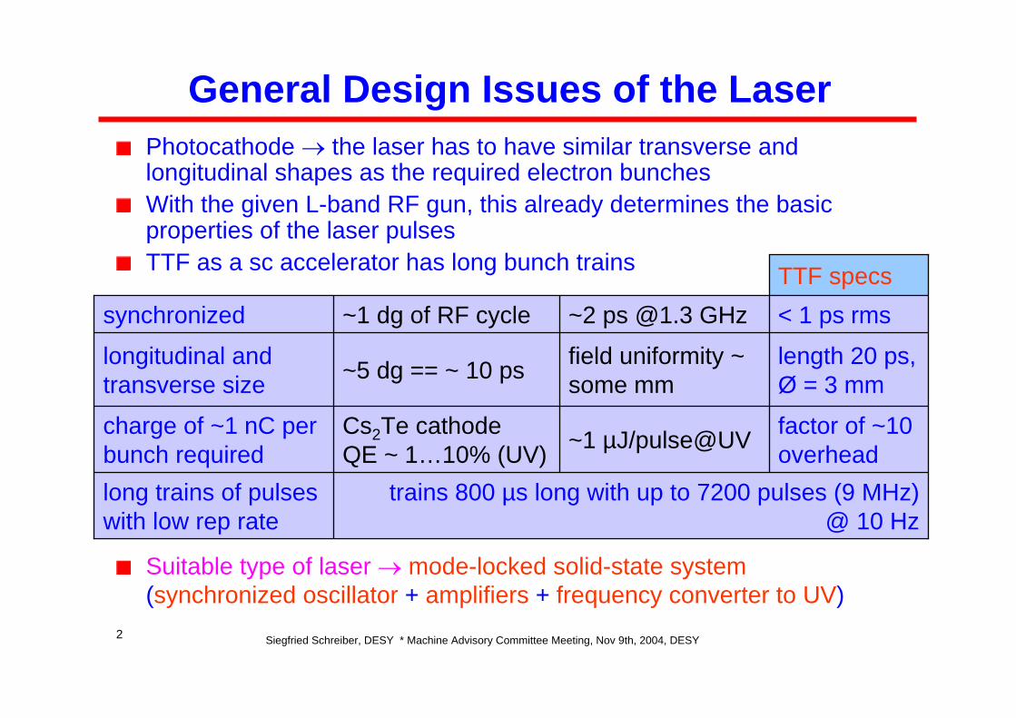
trains 800 µs long with up to 7200 pulses (9 MHz) @ 10 Hz
long trains of pulses with low rep rate
< 1 ps rms~2 ps @1.3 GHz~1 dg of RF cyclesynchronized
factor of ~10 overhead~1 µJ/pulse@UVCs2Te cathode
QE ~ 1…10% (UV)charge of ~1 nC per bunch required
length 20 ps, Ø = 3 mm
field uniformity ~ some mm~5 dg == ~ 10 pslongitudinal and
transverse size
TTF specs
General Design Issues of the LaserPhotocathode → the laser has to have similar transverse and longitudinal shapes as the required electron bunchesWith the given L-band RF gun, this already determines the basic properties of the laser pulsesTTF as a sc accelerator has long bunch trains
Suitable type of laser → mode-locked solid-state system(synchronized oscillator + amplifiers + frequency converter to UV)
Siegfried Schreiber, DESY * Machine Advisory Committee Meeting, Nov 9th, 2004, DESY3
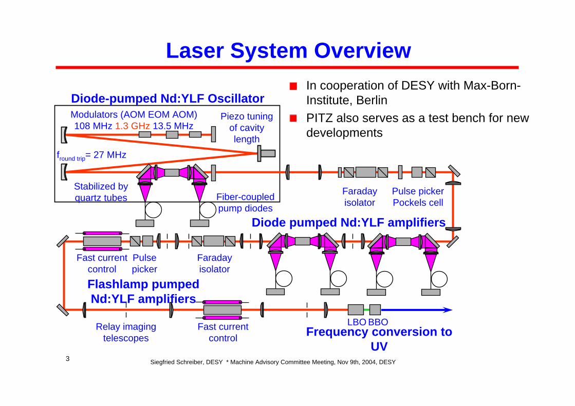
Laser System OverviewIn cooperation of DESY with Max-Born-Institute, BerlinPITZ also serves as a test bench for new developments
fround trip= 27 MHz
Modulators (AOM EOM AOM) 108 MHz 1.3 GHz 13.5 MHz
Faraday isolator
Piezo tuning of cavity length
Stabilized by quartz tubes Fiber-coupled
pump diodes
Pulse picker Pockels cell
Faraday isolator
Fast current control
Fast current control
Diode-pumped Nd:YLF Oscillator
Diode pumped Nd:YLF amplifiers
LBO BBO
Flashlamp pumped Nd:YLF amplifiers
Frequency conversion to UV
Relay imaging telescopes
Pulse picker
Siegfried Schreiber, DESY * Machine Advisory Committee Meeting, Nov 9th, 2004, DESY4
Long Term Running Experience at TTF1
The laser has been upgraded end of 2003The basic design philosophy has been kept:
As simple as possible (avoid components which require frequent adjustments)‘Ready-to-sell’ finish and robustUse well-known technology (laser material, pump sources)Fully integration into the control system
The TTF1 laser ran for 4 years (== 36,000 h or 13•107 s)The oscillator was on during 25,000 h and made 9.2•107 trains, the amplifiers 16,000 h and 6.4•107 trains @ 1 HzTotal on-time oscillator 70%, amplifiers 50%
The major upgrade is in using diode lasers as a pump sourceUp to now 1,500 h with 2.1•107 pulse trains @ 5 Hz delivered
Siegfried Schreiber, DESY * Machine Advisory Committee Meeting, Nov 9th, 2004, DESY5
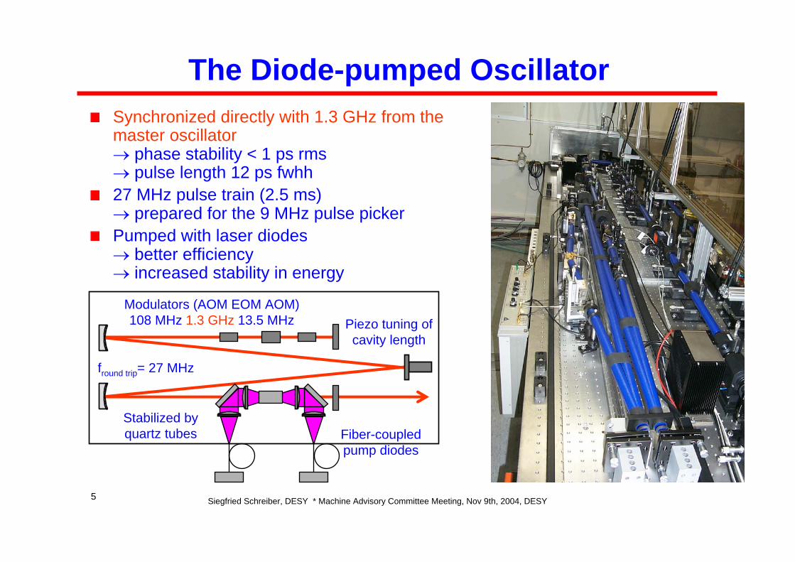
The Diode-pumped OscillatorSynchronized directly with 1.3 GHz from the master oscillator→ phase stability < 1 ps rms→ pulse length 12 ps fwhh27 MHz pulse train (2.5 ms) → prepared for the 9 MHz pulse pickerPumped with laser diodes→ better efficiency → increased stability in energy
fround trip= 27 MHz
Modulators (AOM EOM AOM) 108 MHz 1.3 GHz 13.5 MHz Piezo tuning of
cavity length
Stabilized by quartz tubes Fiber-coupled
pump diodes
Siegfried Schreiber, DESY * Machine Advisory Committee Meeting, Nov 9th, 2004, DESY6
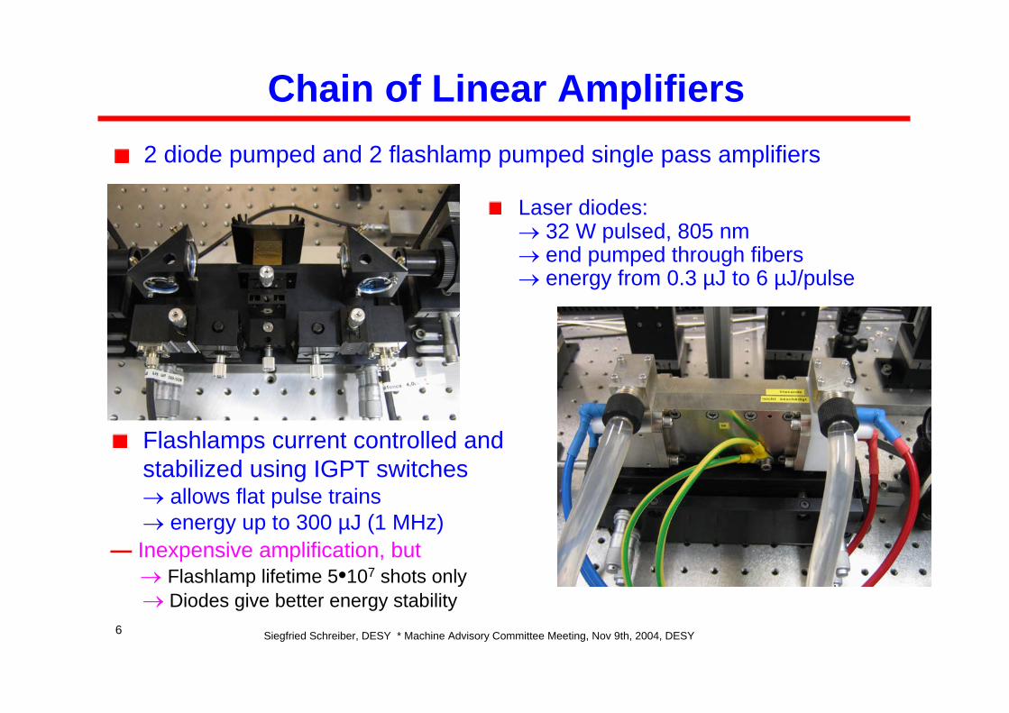
Chain of Linear Amplifiers2 diode pumped and 2 flashlamp pumped single pass amplifiers
Laser diodes:→ 32 W pulsed, 805 nm→ end pumped through fibers→ energy from 0.3 µJ to 6 µJ/pulse
— Inexpensive amplification, but→ Flashlamp lifetime 5•107 shots only→ Diodes give better energy stability
Flashlamps current controlled and stabilized using IGPT switches→ allows flat pulse trains→ energy up to 300 µJ (1 MHz)
Siegfried Schreiber, DESY * Machine Advisory Committee Meeting, Nov 9th, 2004, DESY7
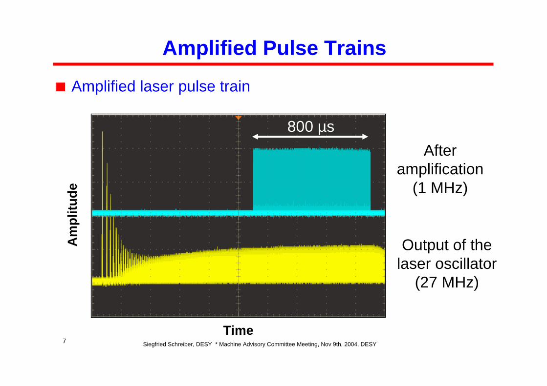
Amplified Pulse Trains
Amplified laser pulse train
Time
Am
plitu
de
800 µs
Output of the laser oscillator
(27 MHz)
After amplification
(1 MHz)
Siegfried Schreiber, DESY * Machine Advisory Committee Meeting, Nov 9th, 2004, DESY8
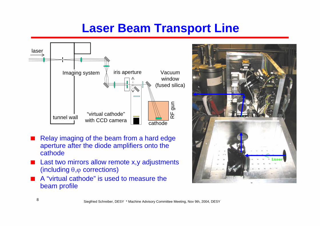
Laser Beam Transport Line
Relay imaging of the beam from a hard edge aperture after the diode amplifiers onto the cathodeLast two mirrors allow remote x,y adjustments (including θ,ϕ corrections)A “virtual cathode” is used to measure the beam profile
laser
RF
gun
iris aperture
“virtual cathode” with CCD camera cathode
tunnel wall
Imaging system Vacuum window
(fused silica)
Siegfried Schreiber, DESY * Machine Advisory Committee Meeting, Nov 9th, 2004, DESY9
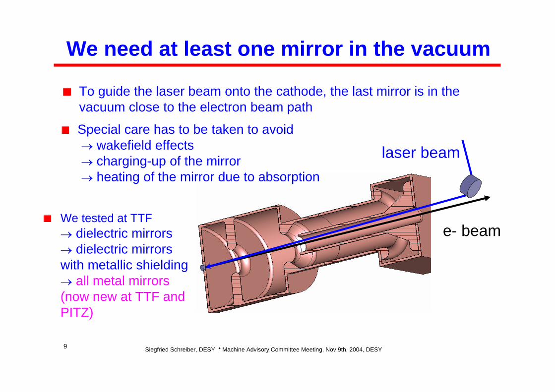
We need at least one mirror in the vacuum
To guide the laser beam onto the cathode, the last mirror is in the vacuum close to the electron beam path
We tested at TTF→ dielectric mirrors → dielectric mirrors with metallic shielding→ all metal mirrors (now new at TTF and PITZ)
laser beam
e- beam
Special care has to be taken to avoid→ wakefield effects→ charging-up of the mirror→ heating of the mirror due to absorption
Siegfried Schreiber, DESY * Machine Advisory Committee Meeting, Nov 9th, 2004, DESY10
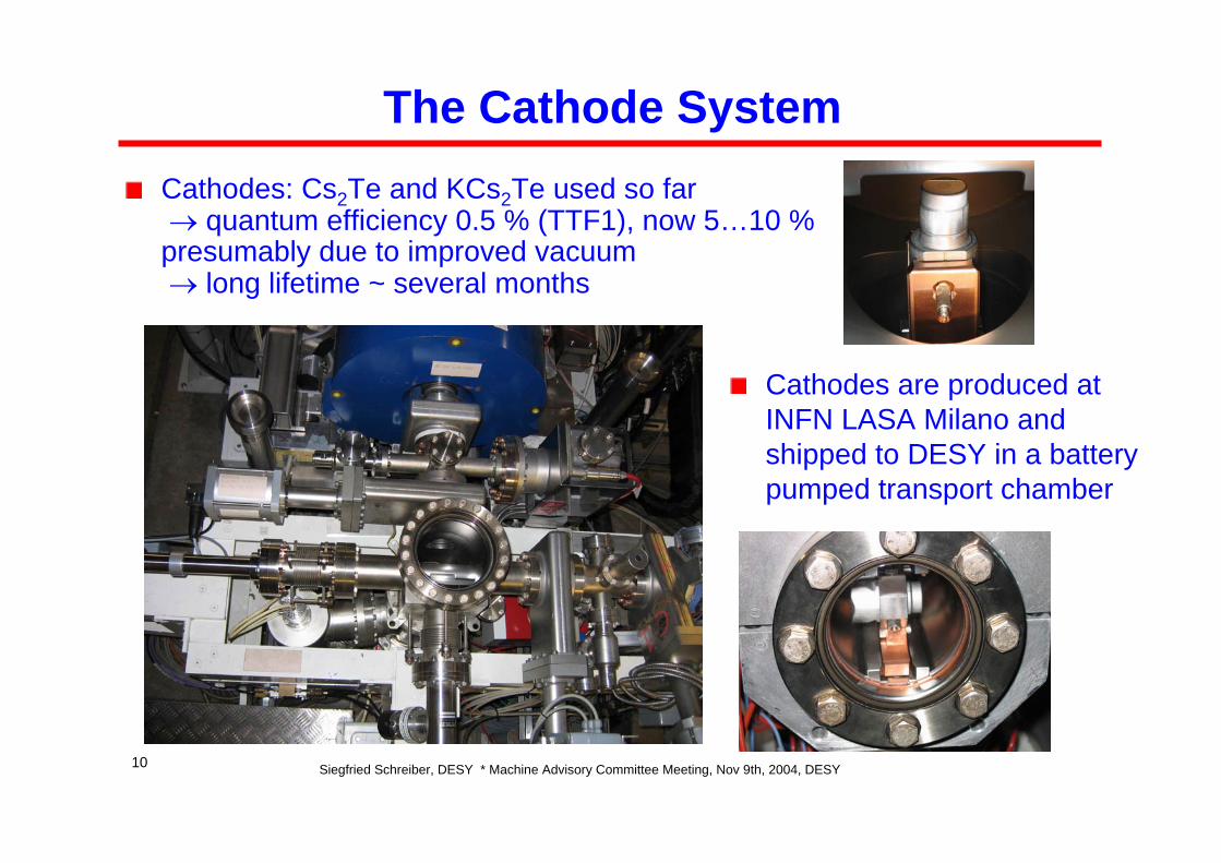
The Cathode SystemCathodes: Cs2Te and KCs2Te used so far→ quantum efficiency 0.5 % (TTF1), now 5…10 %
presumably due to improved vacuum→ long lifetime ~ several months
Cathodes are produced at INFN LASA Milano and shipped to DESY in a battery pumped transport chamber
Siegfried Schreiber, DESY * Machine Advisory Committee Meeting, Nov 9th, 2004, DESY11
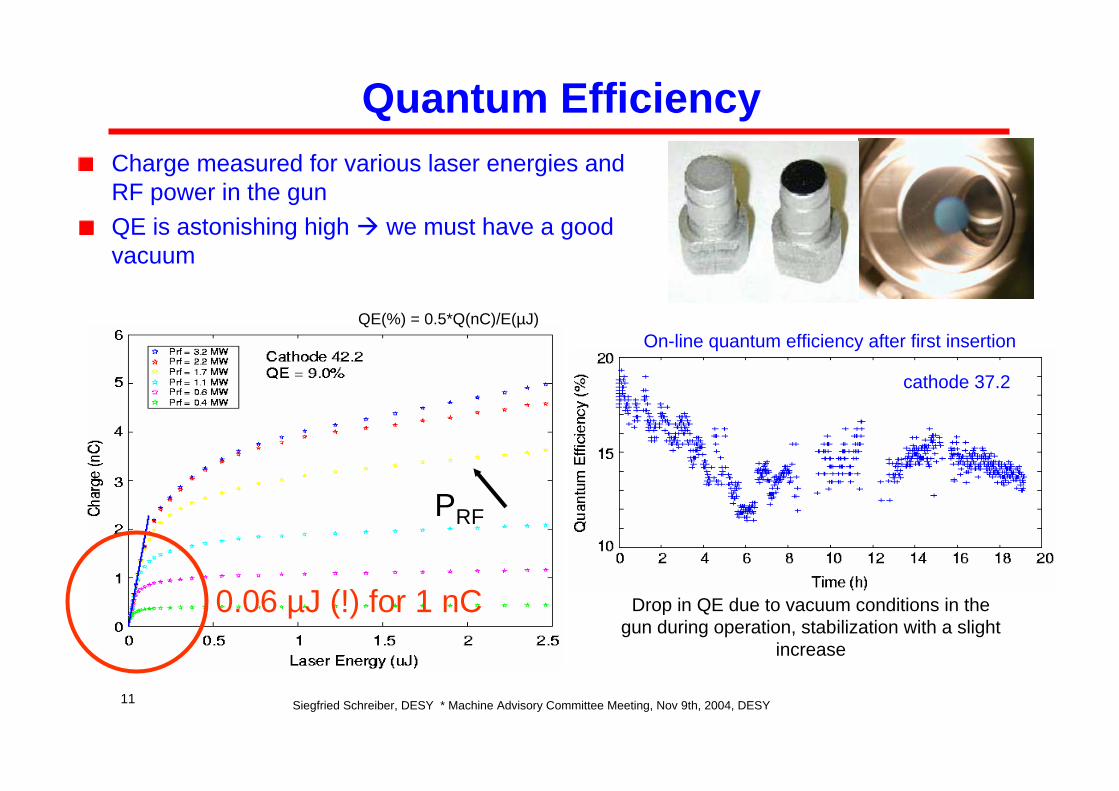
Quantum EfficiencyCharge measured for various laser energies and RF power in the gunQE is astonishing high we must have a good vacuum
PRF
Drop in QE due to vacuum conditions in the gun during operation, stabilization with a slight
increase
On-line quantum efficiency after first insertion
0.06 µJ (!) for 1 nC
cathode 37.2
QE(%) = 0.5*Q(nC)/E(µJ)
Siegfried Schreiber, DESY * Machine Advisory Committee Meeting, Nov 9th, 2004, DESY12
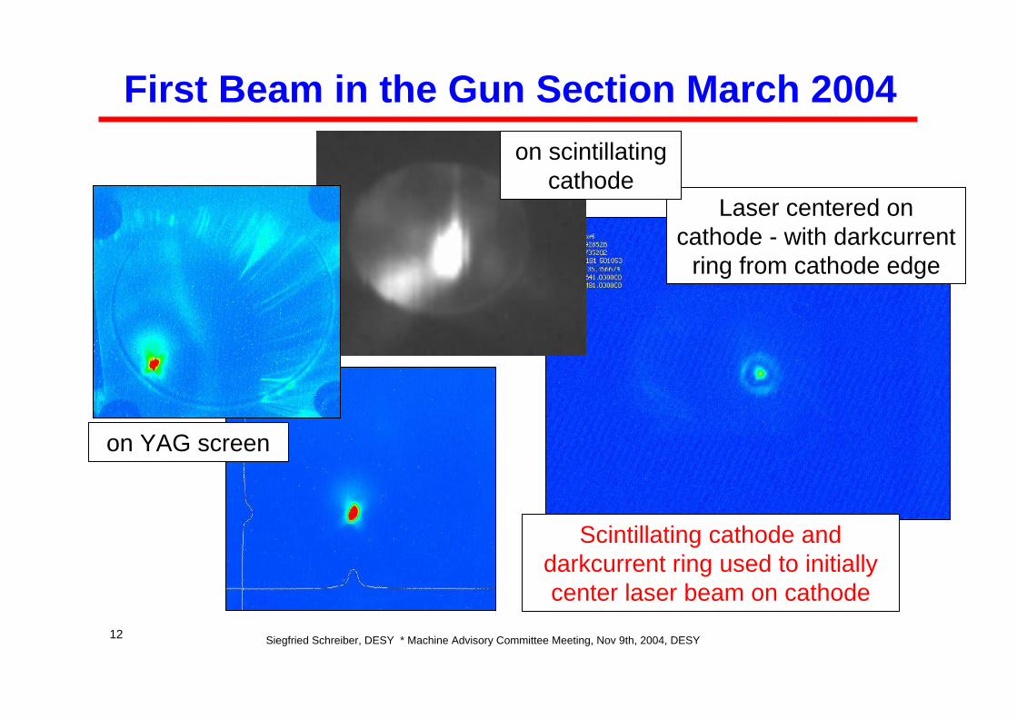
First Beam in the Gun Section March 2004
on YAG screen
Laser centered on cathode - with darkcurrent
ring from cathode edge
Scintillating cathode and darkcurrent ring used to initially center laser beam on cathode
on scintillating cathode
Siegfried Schreiber, DESY * Machine Advisory Committee Meeting, Nov 9th, 2004, DESY13
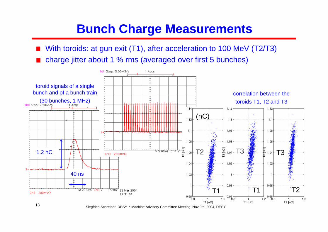
Bunch Charge MeasurementsWith toroids: at gun exit (T1), after acceleration to 100 MeV (T2/T3)charge jitter about 1 % rms (averaged over first 5 bunches)
toroid signals of a single bunch and of a bunch train
(30 bunches, 1 MHz)
40 ns
1.2 nC
correlation between the toroids T1, T2 and T3
T1 T1 T2
T2 T3 T3
(nC)
Siegfried Schreiber, DESY * Machine Advisory Committee Meeting, Nov 9th, 2004, DESY14
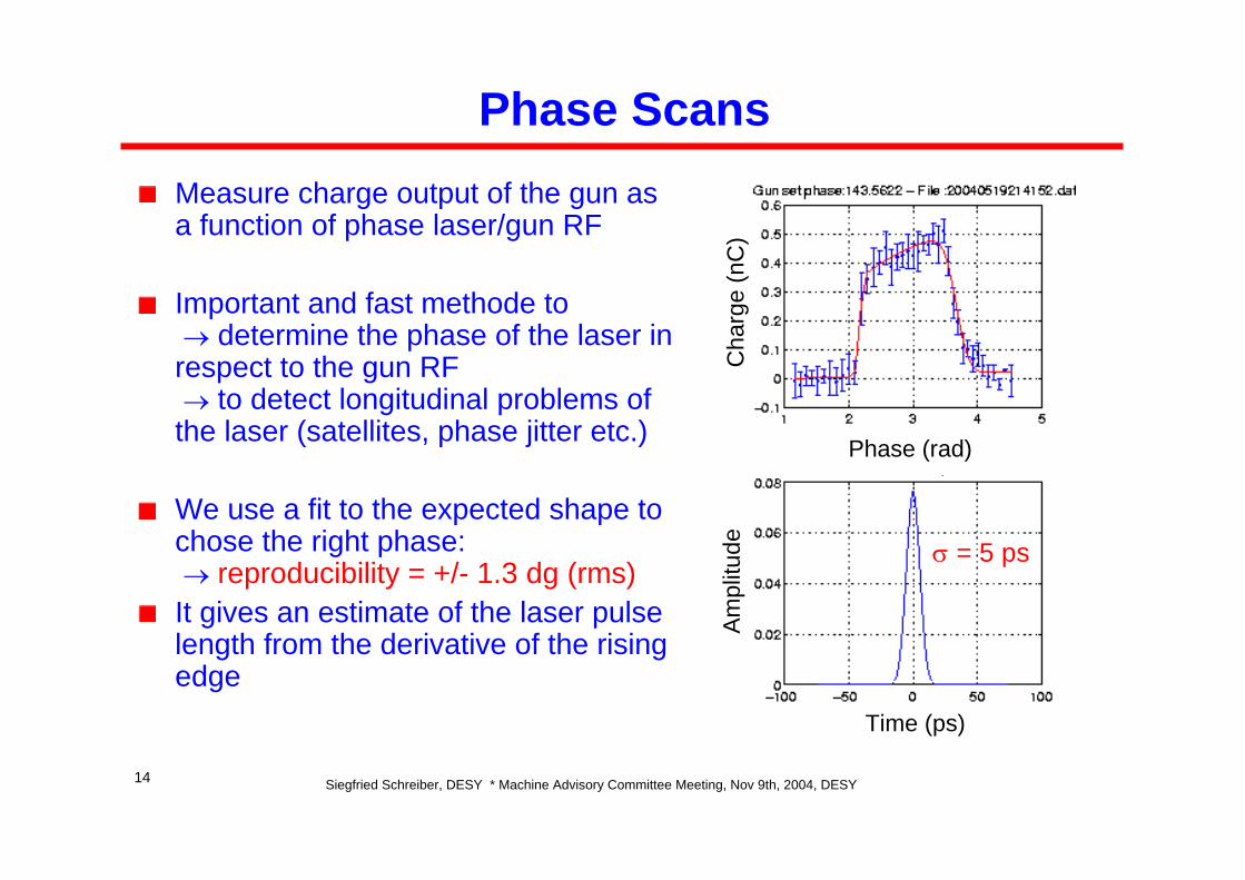
Phase ScansMeasure charge output of the gun as a function of phase laser/gun RF
Important and fast methode to → determine the phase of the laser in
respect to the gun RF→ to detect longitudinal problems of
the laser (satellites, phase jitter etc.)
We use a fit to the expected shape to chose the right phase:→ reproducibility = +/- 1.3 dg (rms)
It gives an estimate of the laser pulse length from the derivative of the rising edge
Cha
rge
(nC
)A
mpl
itude
Time (ps)
Phase (rad)
σ = 5 ps
Siegfried Schreiber, DESY * Machine Advisory Committee Meeting, Nov 9th, 2004, DESY15
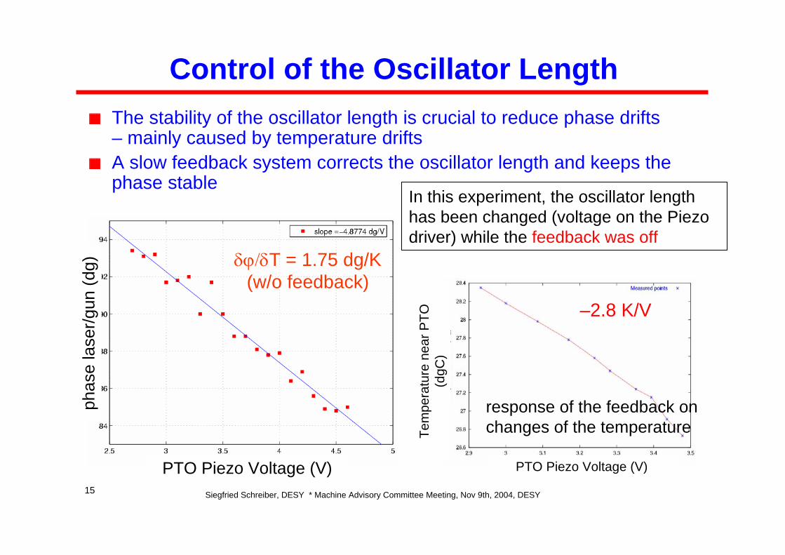
Control of the Oscillator LengthThe stability of the oscillator length is crucial to reduce phase drifts – mainly caused by temperature driftsA slow feedback system corrects the oscillator length and keeps the phase stable
In this experiment, the oscillator length has been changed (voltage on the Piezo driver) while the feedback was off
phas
e la
ser/g
un (d
g)
PTO Piezo Voltage (V)
δϕ/δT = 1.75 dg/K (w/o feedback)
–2.8 K/V
PTO Piezo Voltage (V)
Tem
pera
ture
nea
r PTO
(d
gC)
response of the feedback on changes of the temperature
Siegfried Schreiber, DESY * Machine Advisory Committee Meeting, Nov 9th, 2004, DESY16
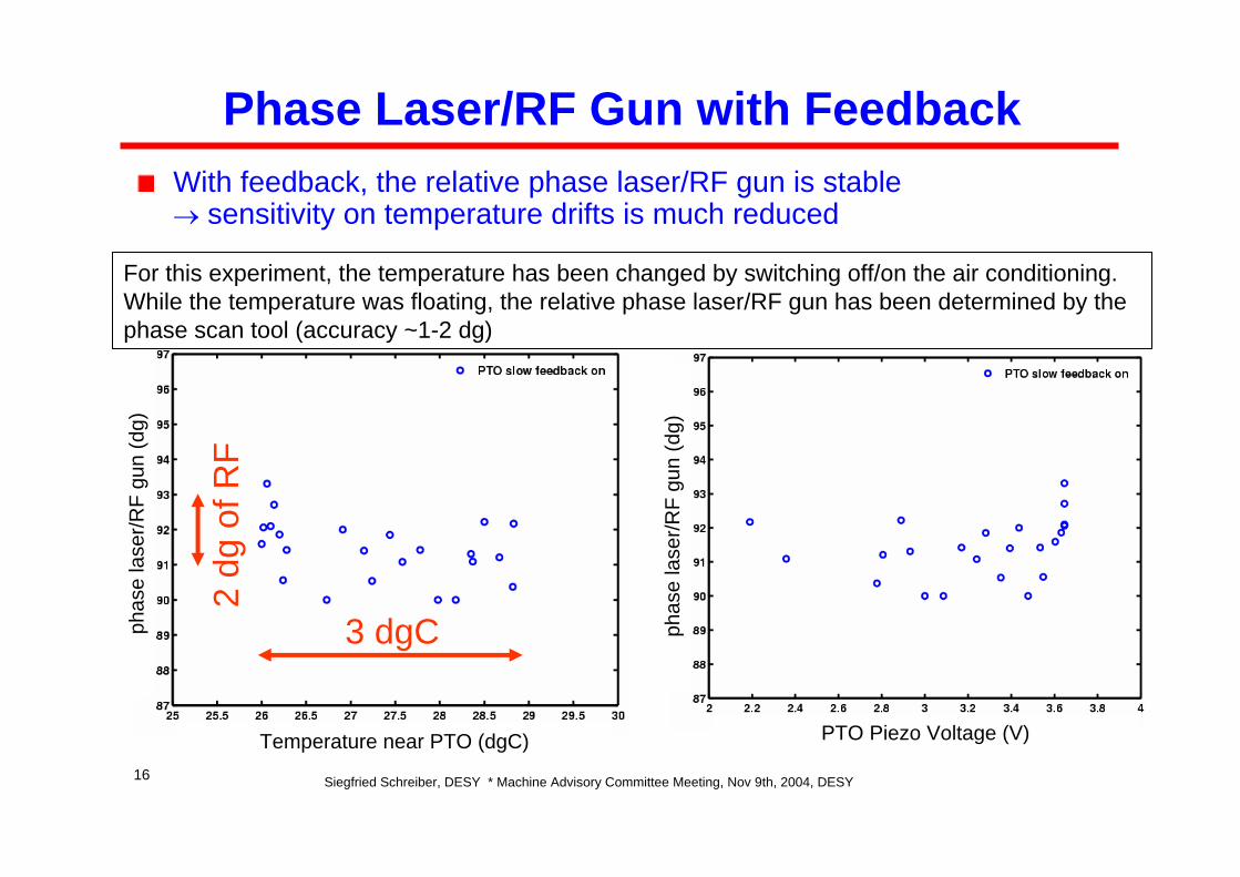
Phase Laser/RF Gun with FeedbackWith feedback, the relative phase laser/RF gun is stable→ sensitivity on temperature drifts is much reduced
Temperature near PTO (dgC)
phas
e la
ser/R
F gu
n (d
g)
PTO Piezo Voltage (V)
phas
e la
ser/R
F gu
n (d
g)
3 dgC
2 dg
of R
FFor this experiment, the temperature has been changed by switching off/on the air conditioning. While the temperature was floating, the relative phase laser/RF gun has been determined by the phase scan tool (accuracy ~1-2 dg)
Siegfried Schreiber, DESY * Machine Advisory Committee Meeting, Nov 9th, 2004, DESY17
3 mm
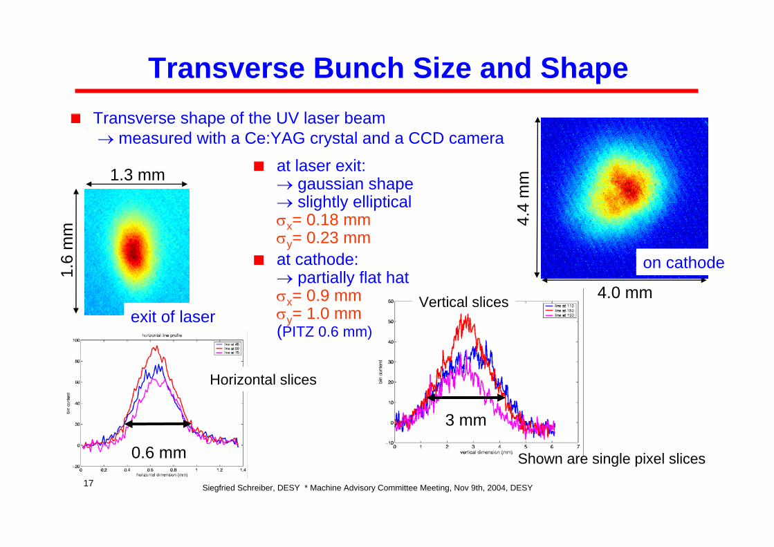
Transverse Bunch Size and Shape
at laser exit:→ gaussian shape → slightly ellipticalσx= 0.18 mmσy= 0.23 mmat cathode:→ partially flat hatσx= 0.9 mmσy= 1.0 mm(PITZ 0.6 mm)
exit of laser
1.6
mm
4.0 mm
4.4
mm
on cathode
1.3 mm
0.6 mm
Transverse shape of the UV laser beam → measured with a Ce:YAG crystal and a CCD camera
Shown are single pixel slices
Vertical slices
Horizontal slices
Siegfried Schreiber, DESY * Machine Advisory Committee Meeting, Nov 9th, 2004, DESY18
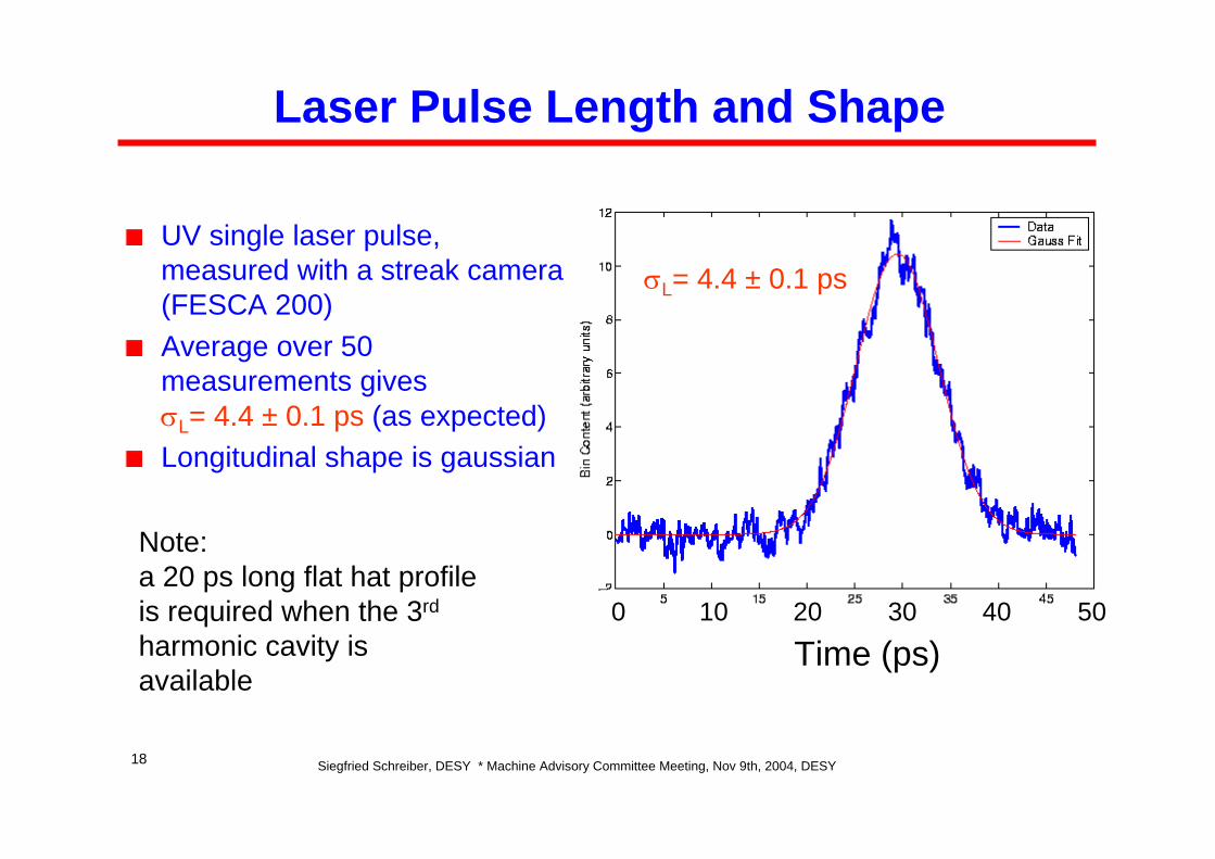
Laser Pulse Length and Shape
UV single laser pulse, measured with a streak camera (FESCA 200)Average over 50 measurements gives σL= 4.4 ± 0.1 ps (as expected)Longitudinal shape is gaussian
Time (ps)0 10 20 30 40 50
σL= 4.4 ± 0.1 ps
Note:a 20 ps long flat hat profile is required when the 3rd
harmonic cavity is available
Siegfried Schreiber, DESY * Machine Advisory Committee Meeting, Nov 9th, 2004, DESY19
1
2
3
12
3
0
0.5
1
y,mmx,mm1
2
3
12
3
0
0.5
1
y,mmx,mm
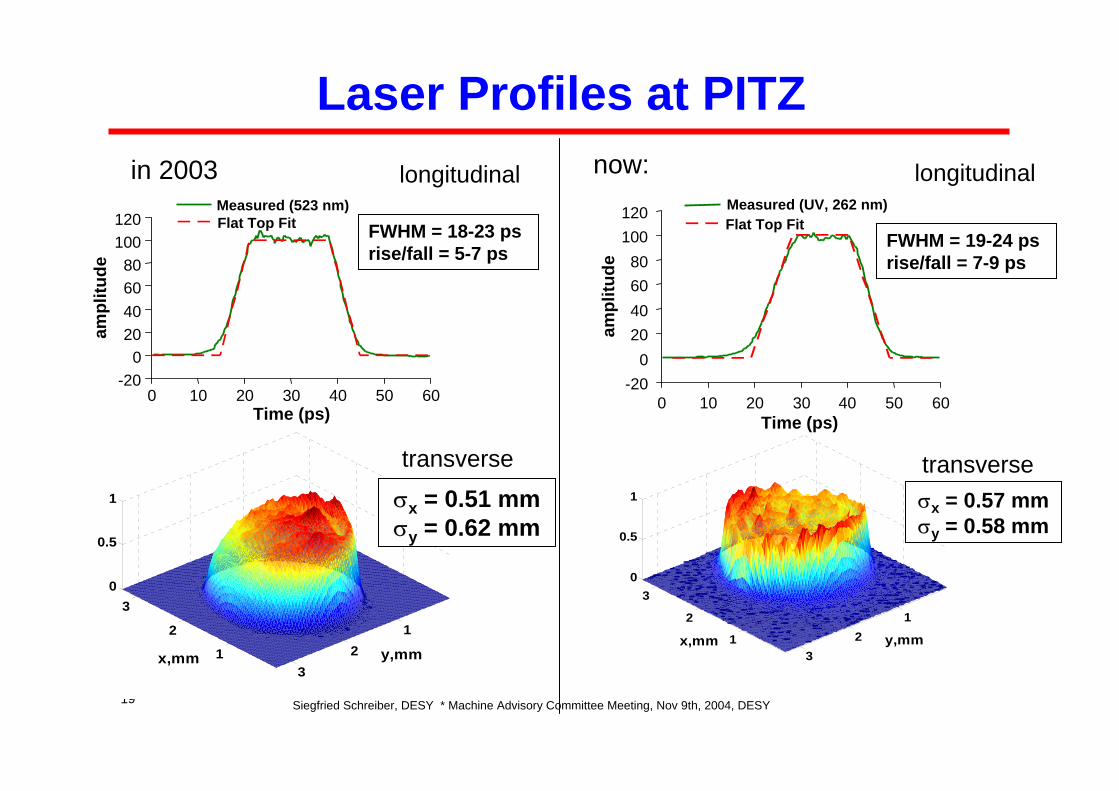
σx = 0.51 mmσy = 0.62 mm
σx = 0.57 mmσy = 0.58 mm
Laser Profiles at PITZin 2003 now:longitudinal
transverse
longitudinal
transverse
-200
20406080
100120
0 10 20 30 40 50 60
ampl
itude
Measured (UV, 262 nm)Flat Top Fit
FWHM = 19-24 psrise/fall = 7-9 ps
Time (ps)
-200
20406080
100120
0 10 20 30 40 50 60Time (ps)
Measured (523 nm)Flat Top Fit FWHM = 18-23 ps
rise/fall = 5-7 ps
ampl
itude
Siegfried Schreiber, DESY * Machine Advisory Committee Meeting, Nov 9th, 2004, DESY20
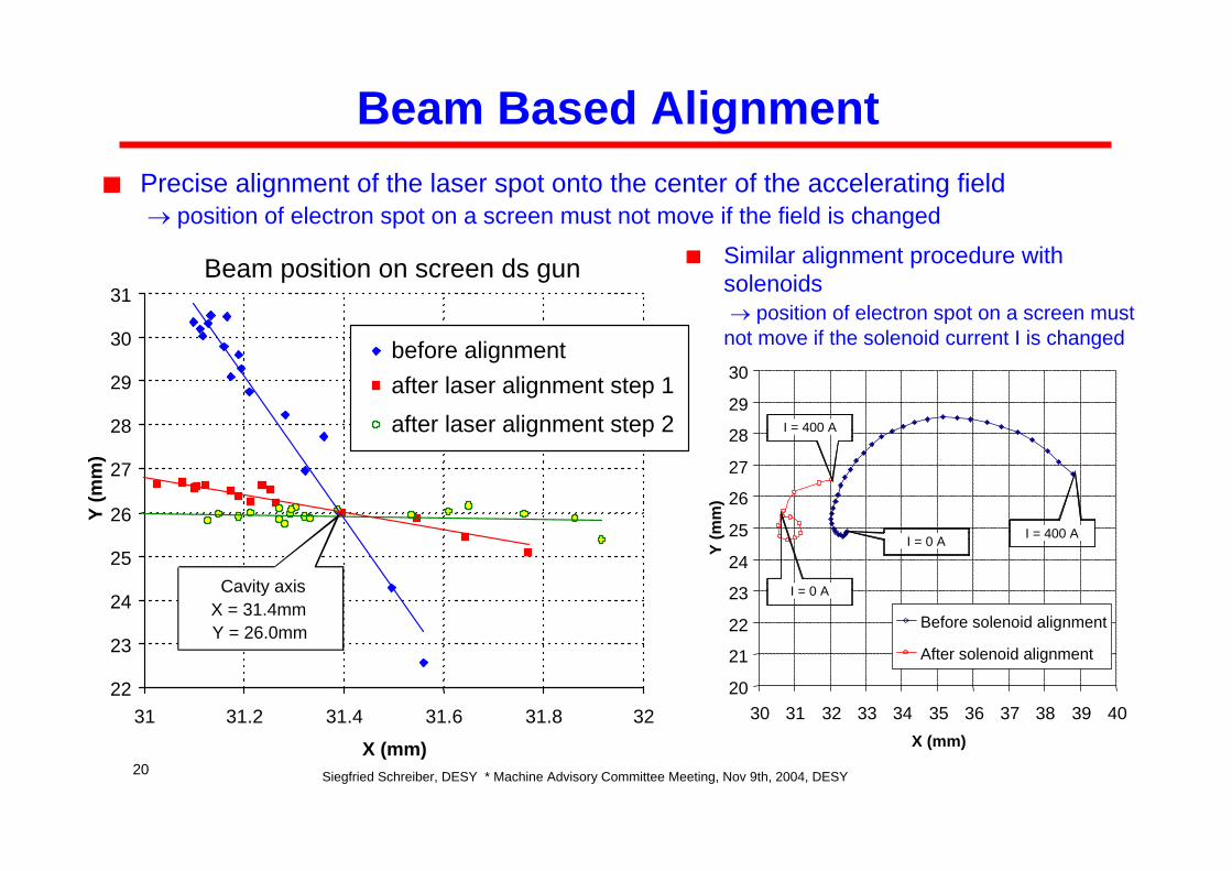
Beam Based AlignmentPrecise alignment of the laser spot onto the center of the accelerating field→ position of electron spot on a screen must not move if the field is changed
22
23
24
25
26
27
28
29
30
31
31 31.2 31.4 31.6 31.8 32
X (mm)
Y (m
m)
before alignmentafter laser alignment step 1after laser alignment step 2
Cavity axisX = 31.4mmY = 26.0mm
Beam position on screen ds gun
20
21
22
23
24
25
26
27
28
29
30
30 31 32 33 34 35 36 37 38 39 40X (mm)
Y (m
m)
Before solenoid alignment
After solenoid alignment
I = 0 A
I = 400 A
I = 0 A I = 400 A
Similar alignment procedure with solenoids → position of electron spot on a screen must
not move if the solenoid current I is changed
Siegfried Schreiber, DESY * Machine Advisory Committee Meeting, Nov 9th, 2004, DESY21
Reliability and other Issues
Frequent problems with the laser system during the last run:• Frequent problems with interrupts in VME crate controlling the laser
system → has been solved now• Pump diodes power supply overload needs manual reset (in average
once per month) → remote control in preparation• Interface machine protection system to laser is late → temporal solution
installed • Short lifetime of CCD cameras in the tunnel • Transverse laser beam spot not satisfactory yet
→ tuning finished up to exit of laser• Replacement of flashlamps required in average every 100 days (5 Hz)
After the installation of an independent chiller, no cooling water problem so far (the most frequent problem at TTF1)
Siegfried Schreiber, DESY * Machine Advisory Committee Meeting, Nov 9th, 2004, DESY22
SummaryLaser upgrade to diode pumped oscillator and diode pump pre-amplifiers gives a better stabilityNo major problems beside normal maintenance up to nowSmooth start-up, first beam 16-Mar-2004Up to now 1,500 h with 2.1•107 pulse trains @ 5 Hz deliveredLaser pulse
• has a longitudinal gaussian shape, σl = 4.4±0.1 ps• transverse neither gaussian nor flat
σx= 0.74 mm, σy= 0.65 mm - requires improvement• Phase jitter < 0.5 ps measured at MBI, we are not yet able to verify this with
beam (~1 ps resolution obtained so far)Mirror inside the vacuum has been replaced by an all metal Al mirrorFurther plans:→ improve transverse beam profile→ longitudinal flat hat with pulse stacker is possible if required→ replace all flashlamp with laser diodes→ install backup laser system


![Cennik produktów ważny od 01.01 - Manufaktura …...Dekor/kolor wykończenie przód/tył wymiar min/max [mm] grubość [mm] czas realizacji standard 3D/3D Laser Line Laser Line Beż](https://static.fdocuments.pl/doc/165x107/5e8e3ad0ddac341f7641b95d/cennik-produktw-wany-od-0101-manufaktura-dekorkolor-wykoczenie-przdty.jpg)