The Element of Statistical Learning Data Mining, Inference and Prediction
Scientific Journals Zeszyty Naukoweof the Maritime University of Szczecin Akademii Morskiej w Szczecinie
Zeszyty Naukowe Akademii Morskiej w Szczecinie 46 (118) 115
2016, 46 (118), 115–121 ISSN 1733-8670 (Printed) Received: 31.08.2015 ISSN 2392-0378 (Online) Accepted: 22.02.2016 DOI: 10.17402/127 Published: 27.06.2016
Optimization of waterway bend widths using computer simulation methods of ship movement
Jarosław Artyszuk1, Rafał Gralak2, Maciej Gucma2, Stanisław Gucma2, Wojciech Ślączka3, Paweł Zalewski2
Maritime University of Szczecin, Faculty of Navigation, 1 Institute of Marine Traffic Engineering 2 Marine Traffic Engineering Centre, 3 Institute of Marine Navigation 1–2 Wały Chrobrego St., 70-500 Szczecin, Poland e-mails: {j.artyszuk; r.gralak; m.gucma; s.gucma; w.slaczka; p.zalewski}@ am.szczecin.pl corresponding author
Key words: marine traffic engineering, waterways, bends in the fairway, simulation methods of optimizing the parameters of waterways, Świnoujście–Szczecin fairway, computer simulation of vessel traffic
AbstractThe paper presents the development of a new simulation method to optimize bends in marine waterways. This method, using results of empirical research and simulation methods, would allow accurate determination of safe manoeuvring areas. The method was used at the stage of detailed design of parameters of the, which is undergoing modernization, to determine the optimum parameters of horizontal curves of the fairway. The study was conducted on the type of manoeuvring simulator called Polaris Kongsberg and attended by pilots from the Szczecin–Swinoujscie Pilot Station. Based on the studies carried out, the maximum safe ship length was deter-mined for the redesigned waterway and the conditions for their safe operation. The maximum lengths of these ships are as follows: cruise Lc = 260 m, container Lc = 240 m and a bulk carrier Lc = 220 m.
Introduction
Horizontal parameters of a waterway bend can be determined by empirical or simulation methods (Gucma et al., 2015b), although empirical methods are less accurate than simulation methods. Empiri-cal methods define the safe width of a manoeuvring area (d) as constant over the entire length of the bend:
d = const (1)
Simulation methods determine the safe width of a manoeuvring area as a variable of the function of bend length (l):
d = f (l) (2)
Methods of computer simulation were used to optimize horizontal parameters of bends in the mod-ernized Świnoujście–Szczecin fairway. To determine
the parameters of the components of the waterway system, an optimization method was used in which the objective function is the cost of building and operating a system of marine waterways, which can be written as follows (Gucma, 2013; Gucma et al., 2015b):
Z = (A1 + A2 + N1 + N2 + Sk) → min (3)
with the constraint:
ttTth
t
xyxyxytsxp D
iDd
.
ijk 1
(4)
where:Di(t) – navigable area at i-th section of the water-
way (the condition of safe depth at moment t is fulfilled);
dijk(1 – α) – safe manoeuvring area of j-th ship manoeuvring in i-th section of the waterway
Jarosław Artyszuk, Rafał Gralak, Maciej Gucma, Stanisław Gucma, Wojciech Ślączka, Paweł Zalewski
116 ScientificJournalsoftheMaritimeUniversityofSzczecin46(118)
under k-th navigational conditions, the area being determined at confidence level 1–α;
Z – cost of construction and operation of waterways;
– cost of construction (reconstruction) of the waterway;
A2 – cost of operation of the waterway;N1 – cost of the construction of a subsystem
for determining ship position (navigation systems);
N2 – cost of navigation systems operation;Sk – vessel operating costs associated with water-
way passage (pilotage, tug assistance, etc.);hxy – water depth at point (x, y);Txy – ship’s draft at point (x, y);Δxy – underkeel clearance at point (x, y).
Computer simulation methods used for the optimization of safe width of waterway bends
Computer simulation methods are used at the stage of detailed design of waterways. The applica-tion of these methods results in an accurate determi-nation of safe manoeuvring areas for ships in service or those expected to operate therein. This refers to the determination of the width of safe manoeuvring areas for intended “maximum ships” in particular sections of the waterway and operating conditions allowable for these ships, at a preset confidence lev-el dijk(1–α). Using the basic navigational condition, a navigable area of the waterway Di(t) is defined as a set of maximum available widths in each (i) sec-tion of the waterway.
In computer simulation methods for determining the width of safe manoeuvring areas of ships, the results were taken from the preliminary design stage where empirical methods are used (PIANC 2014; Gucma et al., 2015b).
The procedure of simulation tests used in the design of marine waterways is carried out in the fol-lowing order (Gucma, Gucma & Zalewski, 2008):1. formulation of the research problem, including
identification of the design objective, simulation methods used and the type of simulators;
2. construction or choice of models of ship movement on the chosen simulator and their verification;
3. design of experimental system and conduct of an experiment;
4. processing and statistical analysis of test results.The formulation of the research problem of the
simulation experiment in the design of marine water-ways is reduced to these steps:
1. determine the research objective;2. determine the level of confidence or acceptable
risk for safe manoeuvring area3. choose a simulation method;4. detect the type of shiphandling simulator.
Simulation tests used at the stage of detailed design of marine waterways employ the preliminary waterway design results. On this basis, the vectors of the parameters of safe operation of “maximum ships” that are used at the initial stage are deter-mined to define parameters of waterway elements (Gucma, 2013):
Wmax = [typ, Lc, B, T, Hst, V, C, Hi] (5)
where:typ − type of “maximum ship”;Lc − length overall of “maximum ship”;B − breadth of “maximum ship”;T − draft of “maximum ship”;Hst − air draft of “maximum ship”;Vi − allowable speed of “maximum ship” in i-th
section of the waterway;Ci − tug assistance in i-th section of the waterway
(number of tugs and bollard pull of each tug);Hi − vector of hydrometeorological conditions
allowable for “maximum ship” in i-th section of the waterway.
When several “maximum ships” obtain compa-rable widths of safe manoeuvring areas at the initial design stage, all such ships qualify for simulation studies. The following may be a case in which sim-ulation studies will be conducted for a number of models with the following vectors of safe operation of the ship:
Wi (Lc = max) Wi (B = max) (6) Wi (T = max)
“Maximum ships” that qualify for simulation tests are called “characteristic ships” of the water-way under examination.
Arranging the experiment and processing the simulation test results are two parts of the simula-tion research procedure that require the researchers to have experience, deep insight, and understanding of the principles of manoeuvring and marine traffic engineering. Statistical analysis of the results of sim-ulation studies must be based on specially designed programs for determining safe manoeuvring areas of a ship at a certain confidence level or at a certain level of acceptable risk.
Designing a simulation experiment system con-sists of:

Optimizationofwaterwaybendwidthsusingcomputersimulationmethodsofshipmovement
Zeszyty Naukowe Akademii Morskiej w Szczecinie 46 (118) 117
• determining the scope of simulation studies;• determining the number of simulation tests in
each series;• defining the characteristics and professional qual-
ifications of the navigators performing simulated manoeuvres.
Simulation tests of the Świnoujście-Szczecin fairway bends
Deepening the Świnoujście–Szczecin fairway to 12.5 m will result in a deeper channel, drawing, lon-ger and broader ships entering the port of Szczecin, hence the problem of determining the optimal width of the Świnoujście–Szczecin fairway for its dredged depth to 12.5 m.
In the initial stage of designing the modernized Świnoujście–Szczecin fairway three “maximum ships” were examined (Gucma et al., 2015a):
• container ship LOA = 210 m;• cruise ship LOA = 260 m;• bulk carrier LOA = 195 m.Two of these “maximum ships”, the cruise ship
and bulk carrier, require the widest path to safely manoeuvre through the bend. The container ship can safely manoeuvre through the bend on a narrower path. Therefore, the two ships that were accepted for simulation tests on the fairway bends are:
• cruise ship LOA = 260 m;• bulk carrier LOA = 195 m.Maximum ships qualified for simulation tests are
called “characteristic ships” (or calculation ships) in reference to the examined waterway.
The aim of the simulation tests was to determine safe manoeuvring areas of “characteristic ships” on the bends and turning basins along the Świnoujście–Szczecin fairway. The simulation study included the following bends:
• Mańków (41.0 km ÷ 43.0 km);• Ińskie and Babina (51.5 km ÷ 55.5 km);• Święta (58.5 km ÷ 61.0 km).The width of safe manoeuvring areas was deter-
mined at a confidence level of 1–α = 0.95. The study used a simulation method of vessel movement in real time (RTS) using non-autonomous models, meaning one in which the ship movement is controlled by a person (pilot or captain).
The simulation tests were conducted on a multi-bridge, shiphandling simulator called Polaris from Kongsberg Maritime AS, with 3D projection visual-ization. This Full Mission Bridge Simulator (FMBS) is operated at the Marine Traffic Engineering Centre (MTEC), Maritime University of Szczecin.
MTEC’s ship navigation and manoeuvring simu-lator is composed of:• FMBS with 270° visual projection, equipped with
live marine and on-screen simulated navigation-al and manoeuvring equipment, including ARPA, ECDIS and DP Class 2 consoles;
• two multitask navigation bridge simulators with 120° visual projection, equipped with live marine and on-screen simulated navigational and manoeu-vring equipment, including one Voith-Schneider tug console and one with azimuth propeller tug console;
• two part-task desktop PC simulators with one-dis-play visual projection and on-screen simulated navigational and manoeuvring equipment;
• instructor room for designing and monitoring simulations.The hydrodynamic modelling application enables
users to build their own ships Available options for these ship models include: control function for two engines, two fixed pitch propellers, controllable pitch propellers, azimuth propellers; conventional and active rudders, as well as bow and stern thrust-ers with six degrees of freedom (pitching, rolling, yawing, heaving, surging and swaying).
User defined, target ships, and navigable waters are visualized in the 3D graphic, using high reso-lution textures, implemented into the simulator via Creator software from Presagis (Multigen). Testing areas are composed of databases combined with live or on-screen simulated navigational, ship handling equipment, and hydrodynamic models of ships and floating objects. The data bases comprise depths, aids to navigation, vision display, charts, wind, waves, currents, tides, fenders, locks, shores, Navtex data, DGPS, VTS, and positioning systems (DGPS, HPR, Artemis, Radius etc.).
The research team built and verified two models of “characteristic ships” with the following parame-ters (Gucma et al., 2015a):
The cruise ship:• LOA = 260 m – length overall;• LBP = 220 m – length between perpendiculars
(also designated as L);• B = 33 m – breadth;• T = 9 m – draft;• m = 45,500 t – displacement (corresponding to the
deadweight capacity of approx. 8000 t);• AL = 8,700 m2 – lateral windage area;• propulsion: twin propellers; 4 x 7875 kW engines
(diesel, total 31 500 kW); propeller type – cpp, turning inwards; stern rudders – Becker; thrust-ers: 3 x 1400 kW (bow) and 2 x 1400 kW (stern).

Jarosław Artyszuk, Rafał Gralak, Maciej Gucma, Stanisław Gucma, Wojciech Ślączka, Paweł Zalewski
118 ScientificJournalsoftheMaritimeUniversityofSzczecin46(118)
The bulk carrier:• LOA = 195 m – length overall;• LBP = 185 m – length between perpendiculars
(also designated as L);• B = 29 m – breadth;• T = 11 m – draft;• m = 47,000 t – displacement, laden ship (cor-
responds to deadweight capacity of approx. 38 000 t);
• AL = 1,200 m2 – lateral windage area;• propulsion: single-propeller; diesel engine
of 8500 kW; controllable pitch propeller, left-handed; conventional rudder; thrusters: none.
Designing an experimental system for simula-tion tests on FMBS comes down to the following tasks:1. Defining the scope of simulation research. Deter-
mination of the number of characteristic series of tests, navigational conditions, and manoeuvring tactics adopted in each series of tests. These con-ditions should be selected so as to maximize the widths of safe manoeuvring areas of “characteris-tic ships”.
2. Determination of the number of simulated manoeuvres (passages) in each series of tests.
3. Selection of the pilots for simulation tests. Deter-mination of the qualifications of persons perform-ing the manoeuvres and maximum numbers of simulations performed by one person in a given series of tests.The following ranges have been developed for
simulation tests of cruise ship and bulk carrier, pro-ceeding along the Świnoujście–Szczecin fairway (V = 8 knots):1. Mańków bend 41.0 km ÷ 43.0 km / ± 250 m:
• passage to Szczecin;• current = 0;• wind = 10 m/s NW and SW.2 series of tests for each “characteristic ship” at two different wind directions NW and SW.
2. Ińskie-Babina bend 51.5 km ÷ 55.5 km / ± 250m:• passage to Świnoujście;• current = outgoing, 0.7 knot;• wind = 10 m/s, S and W2 series of tests for each “characteristic ship” at two different wind directions S and W.
3. Święta bend 58.5 km ÷ 61.0 km / ± 250 m:• passage to Świnoujście;• current = outgoing, 0.7 knot;• wind = 10 m/s, S and W.2 series of tests for each “characteristic ship” at two different wind directions S and W.
The minimum number of manoeuvre simulations in a test series was twelve for a specific wind direc-tion (Gucma, 2001). The simulated manoeuvres were performed by pilots from Szczecin Pilot Station, captains experienced in manoeuvring large vessels. Each captain performed two simulated manoeuvres in a test series.
Analysis of simulation test results for optimization of horizontal Parameters of the Świnoujście–Szczecin fairway bends
Analysis of the results of the simulation studies using best fit tests has showed that:1. There is no statistically significant difference (sig-
nificance level α = 0.05) between the widths of the paths swept by the cruise ship and bulk carrier for these winds:• NW and SW in the Mańków bend;• S and W in the bends: Ińskie, Babina and
Święta.Accordingly, it was assumed, in further analysis that safe manoeuvring areas for individual ves-sels refer to all directions of wind speeds up to 10 m/s.
2. The biggest widths of safe manoeuvring areas in all the bends are swept by the cruise ship, LOA = 260 m.
3. In all the examined bends the widths of safe manoeuvring areas determined by simulation methods are smaller than the widths defined by empirical methods (preliminary design).The results of simulation tests, in the form
of safe manoeuvring areas of the cruise ship and bulk carrier that were determined at a signifi-cance level of 0.95, are presented for the follow-ing Świnoujście-Szczecin fairway bends (Gucma et al., 2015a):
• Mańków bend – Figure 1;• Ińskie bend – Figure 2;• Babina bend – Figure 3;• Święta bend – Figure 4.Figures 1 to 4 include preliminary depth contours
of 12.5 m superimposed at the stage of preliminary design using the MTEC method and safe depth con-tours of 12.5 m determined from simulation tests involving the cruise ship and bulk carrier, in the dia-grams identified as swept paths of 95%.
The navigable area meeting the criteria of the minimum cost of construction and operation and navigational safety conditions designed on the basis of safe manoeuvring areas determined using simula-tion tests studies (see relations 3 and 4).

Optimizationofwaterwaybendwidthsusingcomputersimulationmethodsofshipmovement
Zeszyty Naukowe Akademii Morskiej w Szczecinie 46 (118) 119
5941400
5941450
5941500
5941550
5941600
5941650
5941700
5941750
5941800
5941850
5941900
5941950
5942000
5942050
5942100
5942150
5942200
5942250
5942300
5942350
5942400
5942450
5942500
471500
471550
471600
471650
471700
471750
471800
471850
471900
471950
472000
472050
472100
472150
472200
472250
472300
472350
472400
472450
472500
472550
472600
472650
472700
472750
472800
472850
472900
472950
473000
473050
473100
473150
473200
473250
473300
Shore line
Fairway centre line
Preliminary depth contour 12.5 m
Swept path 95% - bulk carrier
Swept path 95% - cruise ship
Rys. Pasy ruchu masowca, Mańków. Part 1.
[m]
[m]
5931800
5931850
5931900
5931950
5932000
5932050
5932100
5932150
5932200
5932250
5932300
5932350
5932400
5932450
5932500
5932550
5932600
5932650
5932700
5932750
5932800
474500
474550
474600
474650
474700
474750
474800
474850
474900
474950
475000
475050
475100
475150
475200
475250
475300
475350
475400
475450
475500
475550
475600
475650
475700
475750
475800
475850
475900
475950
476000
Shore line
Fairway centre line
Preliminary depth contour 12.5 m
Swept path 95% -bulk carrier
Swept path 95 - cruise ship
Existing depth contour 12.5 m
Rys. Pasy ruchu masowca, Ińskie-Babina. Part 2.
[m]
[m]
Figure 1. Safe manoeuvring areas of the cruise ship and bulk carrier in Mańków bend (41.0 km ÷ 43.0 km of Świnoujście–Szcze-cin fairway). Wind speed of 10 m/s (Gucma et al., 2015a)
Figure 2. Safe manoeuvring areas of the cruise ship and bulk carrier in Ińskie bend (51.5 km ÷ 53.0 km of Świnoujście–Szczecin fairway). Wind speed of 10 m/s (Gucma et al., 2015a)

Jarosław Artyszuk, Rafał Gralak, Maciej Gucma, Stanisław Gucma, Wojciech Ślączka, Paweł Zalewski
120 ScientificJournalsoftheMaritimeUniversityofSzczecin46(118)
5929400
5929450
5929500
5929550
5929600
5929650
5929700
5929750
5929800
5929850
5929900
5929950
5930000
5930050
5930100
5930150
5930200
5930250
5930300
475000
475050
475100
475150
475200
475250
475300
475350
475400
475450
475500
475550
475600
475650
475700
475750
475800
475850
475900
475950
476000
476050
476100
476150
476200
476250
476300
476350
476400
476450
476500
Shore line
Fairway centre line
Preliminary depth contour 12.5 m
Swept path 95% - bulk carrier
Swept path 95% - cruise ship
Existing depth contour 12.5 m
Rys. Pasy ruchu masowca, Ińskie-Babina. Part 4.
[m]
[m]
5925400592542059254405925460592548059255005925520592554059255605925580592560059256205925640592566059256805925700592572059257405925760592578059258005925820592584059258605925880592590059259205925940592596059259805926000
473900473920473940473960473980474000474020474040474060474080474100474120474140474160474180474200474220474240474260474280474300474320474340474360474380474400474420474440474460474480474500474520474540474560474580474600474620474640474660474680474700474720474740474760474780474800
Shore line
Fairway centre line
Preliminary depth contour 12.5 m
Swept path 95% - bulk carrier
Swept path 95% - cruise ship
Existing depth contour 12.5 m
Rys. Pasy ruchu masowca, Święta. Part 2.
[m]
[m]
Figure 3. Safe manoeuvring areas of the cruise ship and bulk carrier in Babina bend (54.5 km ÷ 55.5 km of Świnoujście–Szc-zecin fairway). Wind speed of 10 m/s (Gucma et al., 2015a)
Figure 4. Safe manoeuvring areas of the cruise ship and bulk carrier in Święta bend (58.5 km ÷ 61.0 km of Świnoujście–Szczecin fairway). Wind speed of 10 m/s (Gucma et al., 2015a)
Optimizationofwaterwaybendwidthsusingcomputersimulationmethodsofshipmovement
Zeszyty Naukowe Akademii Morskiej w Szczecinie 46 (118) 121
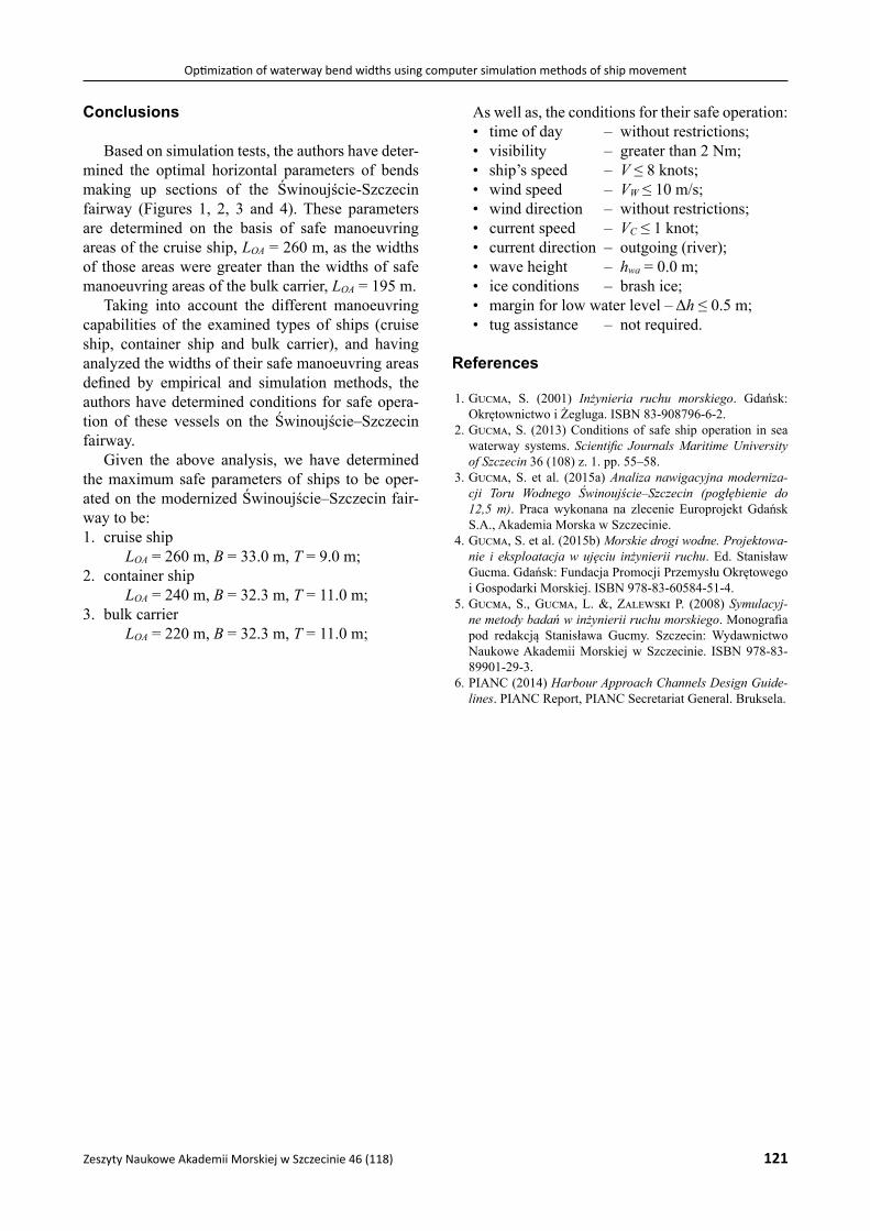
Conclusions
Based on simulation tests, the authors have deter-mined the optimal horizontal parameters of bends making up sections of the Świnoujście-Szczecin fairway (Figures 1, 2, 3 and 4). These parameters are determined on the basis of safe manoeuvring areas of the cruise ship, LOA = 260 m, as the widths of those areas were greater than the widths of safe manoeuvring areas of the bulk carrier, LOA = 195 m.
Taking into account the different manoeuvring capabilities of the examined types of ships (cruise ship, container ship and bulk carrier), and having analyzed the widths of their safe manoeuvring areas defined by empirical and simulation methods, the authors have determined conditions for safe opera-tion of these vessels on the Świnoujście–Szczecin fairway.
Given the above analysis, we have determined the maximum safe parameters of ships to be oper-ated on the modernized Świnoujście–Szczecin fair-way to be:1. cruise ship
LOA = 260 m, B = 33.0 m, T = 9.0 m;2. container ship
LOA = 240 m, B = 32.3 m, T = 11.0 m;3. bulk carrier
LOA = 220 m, B = 32.3 m, T = 11.0 m;
As well as, the conditions for their safe operation:• time of day – without restrictions;• visibility – greater than 2 Nm;• ship’s speed – V ≤ 8 knots;• wind speed – VW ≤ 10 m/s;• wind direction – without restrictions;• current speed – VC ≤ 1 knot;• current direction – outgoing (river);• wave height – hwa = 0.0 m;• ice conditions – brash ice;• margin for low water level – Δh ≤ 0.5 m;• tug assistance – not required.
References
1. Gucma, S. (2001) Inżynieria ruchu morskiego. Gdańsk: Okrętownictwo i Żegluga. ISBN 83-908796-6-2.
2. Gucma, S. (2013) Conditions of safe ship operation in sea waterway systems. Scientific Journals Maritime University of Szczecin 36 (108) z. 1. pp. 55–58.
3. Gucma, S. et al. (2015a) Analiza nawigacyjna moderniza-cji Toru Wodnego Świnoujście–Szczecin (pogłębienie do 12,5 m). Praca wykonana na zlecenie Europrojekt Gdańsk S.A., Akademia Morska w Szczecinie.
4. Gucma, S. et al. (2015b) Morskie drogi wodne. Projektowa-nie i eksploatacja w ujęciu inżynierii ruchu. Ed. Stanisław Gucma. Gdańsk: Fundacja Promocji Przemysłu Okrętowego i Gospodarki Morskiej. ISBN 978-83-60584-51-4.
5. Gucma, S., Gucma, L. &, Zalewski P. (2008) Symulacyj-ne metody badań w inżynierii ruchu morskiego. Monografia pod redakcją Stanisława Gucmy. Szczecin: Wydawnictwo Naukowe Akademii Morskiej w Szczecinie. ISBN 978-83-89901-29-3.
6. PIANC (2014) Harbour Approach Channels Design Guide-lines. PIANC Report, PIANC Secretariat General. Bruksela.