Operation and Maintenance Documentation · The GUARD PRO industrial air curtains are designed to...
15
Operation and Maintenance Documentation SONNIGER Polska Sp. z o.o. Sp.K. ul. Śląska 35/37, 81-310 Gdynia, Poland, infolinia 801 055 155, tel. + 48 58 785 34 80, www.sonniger.com Sąd Rejonowy Gdańsk-Pólnoc, VIII Wydzial Gospodarczy Krajowego Rejestru Sądowego, KRS 0000504509 , NIP 586 227 35 14,Regon 22154369 kapital zakladowy: 1.655.000 PLN
Transcript of Operation and Maintenance Documentation · The GUARD PRO industrial air curtains are designed to...

Operation and Maintenance Documentation
SONNIGER Polska Sp. z o.o. Sp.K. ul. Śląska 35/37, 81-310 Gdynia, Poland, infolinia 801 055 155, tel. + 48 58 785 34 80, www.sonniger.com
Sąd Rejonowy Gdańsk-Północ, VIII Wydział Gospodarczy Krajowego Rejestru Sądowego, KRS 0000504509,
NIP 586 227 35 14,Regon 22154369 kapitał zakładowy: 1.655.000 PLN

Operation and Maintenance Documentation of GUARD PRO air curtains v201708
www.sonniger.com 2
1. PURPOSE OF THE DEVICE
The industrial air curtain is intended to be used in regions with a moderate and cold climate, in spaces where temperature
ranges from -15 to +40°C and of relative humidity up to 80% (at the temperature of +25°C), in conditions free from external
factors such as pollens, hydrometeor (horizontal precipitation) and chemical vapors.
In winters, air curtains protect against heat loss in rooms which is possible due to the airstream suitably directed that protects
the entrance of cold air into a heated space. In summers, the curtains may be used as cooling devices preventing the entry of
hot air from outside as well as air pollutants.
The GUARD PRO industrial air curtains are designed to protect against heat losses in the gateways of buildings of medium and
high capacity especially such as the followings:
warehouse and production halls, Loading/unloading sections in supermarkets and large commercial premises, Car showrooms and service stations, exhibition surfaces
2. BASIC TECHNICAL PARAMETERS
* for water parameters 90/70 C, inlet air temperature 0 C
max temperature of heating agent 130°C
Operation and Maintenance Documentation of GUARD PRO air curtains v201708
www.sonniger.com 3
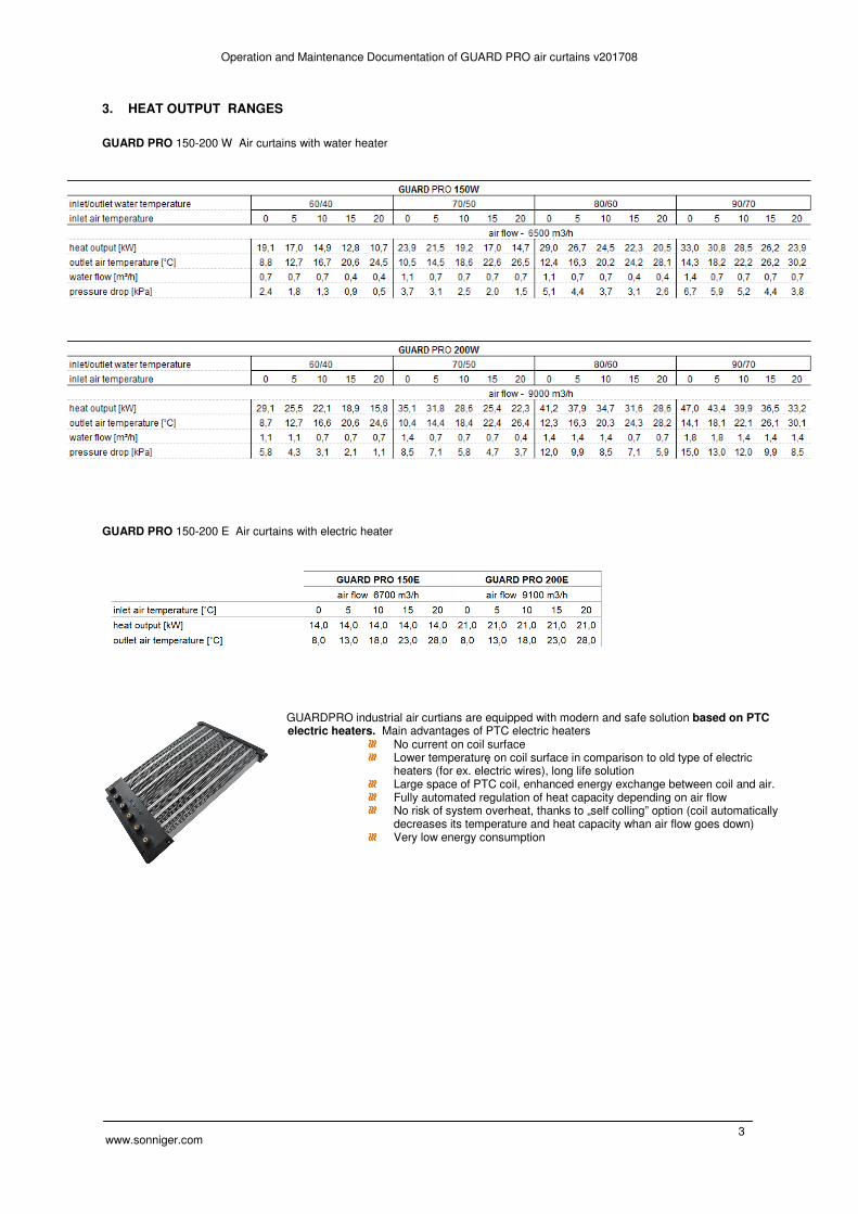
3. HEAT OUTPUT RANGES
GUARD PRO 150-200 W Air curtains with water heater
GUARD PRO 150-200 E Air curtains with electric heater
GUARDPRO industrial air curtians are equipped with modern and safe solution based on PTC E electric heaters. Main advantages of PTC electric heaters
No current on coil surface Lower temperaturę on coil surface in comparison to old type of electric
heaters (for ex. electric wires), long life solution Large space of PTC coil, enhanced energy exchange between coil and air. Fully automated regulation of heat capacity depending on air flow No risk of system overheat, thanks to „self colling” option (coil automatically
decreases its temperature and heat capacity whan air flow goes down) Very low energy consumption

Operation and Maintenance Documentation of GUARD PRO air curtains v201708
www.sonniger.com 4
4. GENERAL AND SAFETY PRINCIPLES
The GUARD PRO air curtains are manufactured in compliance with the rules and standards concerning quality, ecology, utility
and work comfort . Before starting the device be sure to read the Manual carefully.
The GUARD PRO air curtains are delivered ready-to-use in a cardboard package that is to protect from any mechanical
damages. The package consists of: the device, the Manual (Operation and Maintenance Documentation) and the Guarantee. If
the optional automatic control ordered, it shall be delivered in a separate package. Make sure all the aforementioned elements
are in the package immediately after the delivery. In the absence of any element, please fill in the suitable carrier document.
NOTICE!
Do not use the curtain in rooms containing any flammable and/or combustible substances, biological substances or in
environments with corrosive air components.
Do not use the curtain in rooms with relative humidity above 80%
Do not leave the curtain ON unattended for longer periods
Do not use the curtain without proper grounding
Do not turn on the curtain with protective cover on
Before conducting any maintenance or cleaning work or during the break in operation for an extended period of time,
make sure you unplug the power cable
To connect the air curtain, use a supply cable with a fork that protects against unintended disconnecting from the
power
When the air curtain is connected directly to the cable, please make sure there is a splitter protecting against any
undesired disconnecting
Pay special attention while transporting the device not to damage the casing
When the device is being operated, ensure the safety rules in accordance with the labor standards relating to the
operation of any electrical devices
Do not place any objects on the curtain or reduce the airflow in order to ensure the fire safety and if sparks or a
damaged supply cable noticed, discontinue the operation immediately
Electricity network, to which the curtain is connected, should be protected against overloading and short circuit
CAUTION!
For reasons of serious danger to electric shock any exchanges of supply cable must be performed by a qualified
specialist
For reasons of serious danger to electric shock disconnect the power supply prior to conducting any repair or
maintenance work
Any leakage repairs of the heating medium in the device, of which pipes are under pressure, is strictly prohibited
Cut-off/stop valve must be used to supply a heating medium
It is prohibited to connect grounding-type plug to water pipe, gas tubes, lightning conductors, telephone or antenna
network
Wait for at least 3 hours before connecting the device to the supply power if the temperature while transporting is
below zero
NOTICE ! . ���� Before mounting the device, read the manual carefully and adhere to the rules concerning the mounting
procedures. Not applying to the rules may result in the inappropriate functioning of the device and the loss of the guarantee rights.
���� Pay special attention when working with electrical elements of the device.

Operation and Maintenance Documentation of GUARD PRO air curtains v201708
www.sonniger.com 5
5. ASSEMBLY Before mounting the unit, take into consideration the followings:
accessibility/easy access for any servicing and maintenance works access to water and electrical installation possibility to mount the curtain directly at the gate entrance
It is advisable to mount the device to the wall or the ceiling above the doorway on supporting mount pins or supporting constructions ( shapes and dimensions of the supporting construction may be individually designed in compliance with durability and strength requirements). Pay special attention to proper leveling of the device. If the device is not placed in a horizontal or vertical position, it may result in damaging the fan and consequently malfunctioning of the device. The air inlet and outlet must not be blocked by any objects. While installing the unit, remember to provide easy access to the control panel. A few curtains of the same type may be installed in case of a bigger doorway. They must be assembled side-by-side to make an uninterrupted stream of air. The curtain is mounted horizontally or vertically for permanent (on the left/right side of the doorway). The GUARD PRO air curtain is advised to be wider (in case of horizontal mounting) or higher (in case of vertical mounting) than the gate way. If you decide on ACTIVE PROTECTION system, which is the assembly of curtains with water exchanger and without one, you have to mount air curtains with water exchangers on the bottom. When connecting the curtain, make sure that maintenance work is possible to be conducted. On both connection nozzles manual shut-off valves should be installed in case of the necessity of disconnecting the unit. The hot water medium supply must be connected in accordance with the marking on the casing (inlet/outlet). When pipes being screwed to the heat exchanger make sure you secure the inlet connection of the heater to protect it against the torque (that may cause leakage in the heat exchanger). The connections of heating medium with the threaded nozzles DIN 3/4” should be based on the project carried out by an authorized designer. In case of connecting the curtain to the heating network with no mixing module, a water filter must be installed.
Connecting GUARDPRO curtains
The GUARDPRO multi-purpose connector is designed to connect curtains and to mount curtains to the ceiling (in case of
horizontal mounting) or to the wall (in case of vertical mounting). The GUARDPRO multi-purpose connector is not included in
the content of the delivery and is available optionally. The connector should be installed in accordance with the figures below.
The required number of the GUARDPRO multi-purpose connectors may be calculated from the formula below
Installation of connector inside the curtain Installation of connector at the back of the
NOTICE ! . ���� Pay special attention to proper leveling of the device. If the device is not placed horizontally or vertically, it may result
in damaging the fan and consequently the malfunction of the device.
���� To sustain proper functioning of the device, keep safe distances as given in Figure below.
Horizontal assembly (N – number of curtains) N x 4 = number of GUARDPRO multi-purpose connectors Vertical assembly (N - number of curtains) (N x 4) – 2 = number of GUARDPRO multi-purpose connectors

Operation and Maintenance Documentation of GUARD PRO air curtains v201708
www.sonniger.com 6
Horizontal assembly:
Vertical assembly:
6. AUTOMATIC CONTROL SYSTEM - CONTROLBOX S3 GUARDPRO switch and power cabinet The GUARD PRO curtain may be powered by any switch and power board made by a qualified person in accordance with the included Operational and Maintenance Documentation. Switch and power system must contain main/maintenance switch, fan’s current protection system, a relay (ordered optionally) controlled by a door switch during the operation with door opening/closing application. CONTROLBOX S3 GUARD PRO switch and power board is available optionally and may be applied for maximum 3 GUARD PRO curtains (maximum 9 fans). CONTROLBOX S3 GUARD PRO is made in vacuum-tight casing, connections are made on printed circuit board; additionally removable connectors were used for the installer’s convenience. Basic functions of CONTROLBOX S3 GUARD PRO:
Main and additional current protection Possibility to connect DOORSTOP door switch (start/stop at the moment of opening gate) Possibility to connect SPEEDER S2 speed regulator (for two GUARD PRO curtains) Possibility to connect SPEEDER S3 speed regulator (for three GUARD PRO curtains) Delivery does not include main/maintenance switch
To mount the curtain vertically make sure the air
outlet of the curtain is as close as possible to the
doorway and air gap is at the height of the upper
edge of the entry. Please, make sure to keep the
distance of about 300 mm between the outlet
casing and the wall.
To mount two GUARDPRO curtains one above
the other, it is necessary to use the GUARDPRO
multi-purpose connector to install the curtain to
the wall.
To mount GUARDPRO curtain to the floor, use
vertical holder/support, which is used to attach the
curtain to the EURO pallet (for the period of
transport). The support is included in the delivery.
The curtain must be attached to the floor from
each side and its rear side as shown in Figure.
To mount the curtain horizontally in a proper
way, keep the distance of min 300mm from the
rear side of the device.
To mount the GUARDPRO curtain to the
ceiling, use the GUARDPRO multi-purpose
connector. Mounting pins of diameter 11 may
be attached to the connector (not included in
the delivery).

Operation and Maintenance Documentation of GUARD PRO air curtains v201708
www.sonniger.com 7
7. ELECTRICAL CONNECTION DIAGRAMS To connect the curtain use a 3-core copper cable of minimal diameter 3x1,5mm² for two curtains (up to 6 fans) or 3x2,5mm² for 3 curtains (up to 9 fans). The electrical installation and connection to power supply must be done in compliance with the existing regulations and standards for building industry. The electric network, to which the device is to be connected, should protect the device against overloading and short circuit. It is necessary to use protective grounding. Any electrical installation works and the connection to supply power must be conducted in accordance with the applicable building regulations and standards. The connection of the unit to the power supply must be conducted by a qualified specialist who is familiar with the Manual. Fan’s motor is equipped with internal thermal protection against overheating. Power cable and a main switch are not included in the set. Also the DOORSTOP door contact switch can be installed; it turns off the GUARD PRO curtain when the door is being closed and the moment the door is being opened the GUARD PRO curtain starts operating accordingly to the parameters set in the control panel of the device. The regulation of air flow of GUARD PRO curtains by SPEEDER S2 - 10A or SPEEDER S3 - 14A speed regulator which is available optionally.
7.1 Connection scheme for GUARDPRO W (water coil) and C (without coil) with a switch and power board carried out
by an installer.

Operation and Maintenance Documentation of GUARD PRO air curtains v201708
www.sonniger.com 8
7.2 Connection scheme for GUARDPRO W (water coil) and C (without coil) with CONTROLBOX S3 and SPEEDER S2 or SPEEDER S3 speed regulator. NOTICE! A dashed line indicates factory-mounted jumpers that enables the operation of CONTROLBOX S3 without SPEEDER speed regulator. When installing the SPEEDER controller, jumpers must be taken out.
NOTICE!
���� DURING CONNECTION OF MAIN ELECTRICAL SUPPLY OF CONTROL BOX, POLARITY (L-N CONNECTION)
MUST BE KEPT AS PRESENTED ON ABOVE SCHEME. L-N CONNECTION CANNOT BE MIXED (CONNECTED IN
OPPOSITE WAY)!
���� A dashed line indicates factory-mounted jumpers that enables the operation of CONTROLBOX S3 without SPEEDER
speed regulator. When installing the SPEEDER controller, jumpers must be taken out.
���� Required main priotection - fuse C16 [A]
���� Required electrical supply wires - 3 x 1,5 mm² for 2 GUARDPRO curtains (up to 6 fans) or 3 x 2,5 mm² for 3 pcs
GUARDPRO curtains (up to 9 fans)
���� Electrical connection, maitanance and service operations may be run while main supply is OFF. Only qualified staff is
allowed to run above operations

Operation and Maintenance Documentation of GUARD PRO air curtains v201708
www.sonniger.com 9
Electrical connection scheme for GUARDPRO E (electric heater)
Before starting of electrical connection please veryfy if power supply and frequency corresponds to requirements of GUARDPRO (presented on product stikcer and techncial manual)
GUARDPRO are equipped with singe phase fans (1~230 V/50 Hz) it is required to use additional protection for overload and shor circuit.
It is not allowed to start up GUARDPRO without grounded line.
7.3 Connection scheme for GUARDPRO E (electric heater) with a switch and power board carried out by an installer.
NOTICE! Supply of electrical heaters 3 x 400V/50 Hz ���� GUARDPRO 150E – supply wires min 5 x 4mm2, required protection B25
���� GUARDPRO 200E – supply wires min 5 x 6mm2, required protection B40

Operation and Maintenance Documentation of GUARD PRO air curtains v201708
www.sonniger.com 10
7.4 Connection scheme for GUARDPRO E (electric heater) with CONTROLBOX S3 and SPEEDER S2 or SPEEDER S3 speed regulator.
Operation and Maintenance Documentation of GUARD PRO air curtains v201708
www.sonniger.com 11
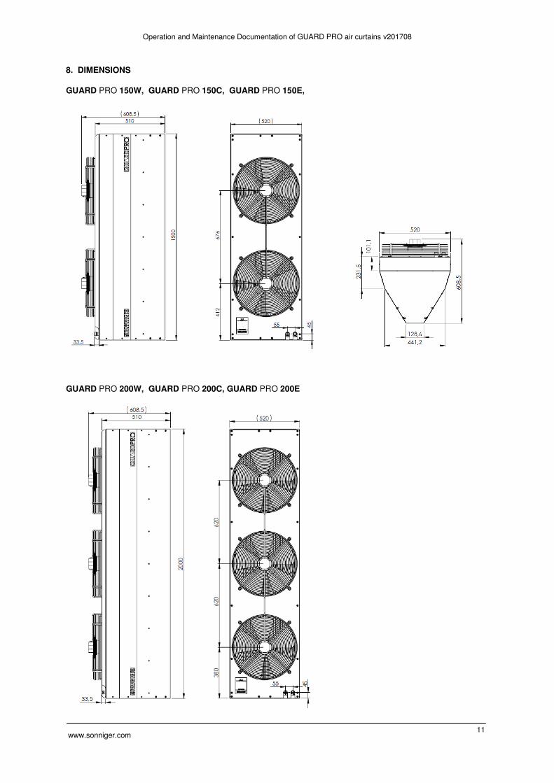
8. DIMENSIONS
GUARD PRO 150W, GUARD PRO 150C, GUARD PRO 150E,
GUARD PRO 200W, GUARD PRO 200C, GUARD PRO 200E

Operation and Maintenance Documentation of GUARD PRO air curtains v201708
www.sonniger.com 12
9. OPERATION AND MAINTENANCE
The engine and fan used in the GUARD PRO air curtains are maintenance-free devices but regular check-ups are advised, especially motor and bearing (fan’s rotor should rotate freely, free from any axial and radial throws/run-outs and undesired knocks/rattles. The heat exchanger requires systematical cleaning all dirts /impurities off. Before the start of the heating period, the heat exchanger is advised to be cleaned with compressed air directed to the air outlets; there is no need for dismantling the device. Pay special attention when cleaning the exchanger’s fin due to high possibility of damaging them. If the fin is bent, use a special tool. If the device has not been used for a longer period of time, unplug it before the next use. The heat exchanger is not equipped with any anti-freeze protection device. The heat exchanger may be damaged if the room temperature goes below 0°C. If the device is to operate in a room where the temperature goes below 0°C, anti-freeze liquid must be added to the water circulation/system. Anti-freeze liquid must be appropriate for the material the exchanger is made of (copper), as well as other elements of the hydraulic system/circulation. The liquid must be diluted with water accordingly to the manufacturer’s recommendation.
NOTICE !
���� Any and all repair and maintenance works must be conducted with the power off and the heat input
disconnected.
���� Only suitably qualified staff well acquainted with the safety regulations concerning handling with an electrical
device must be employed when the device is being installed, started and operated
���� In the event of coolant leak, when the water system is under pressure, any repairs of the leakage are strictly
prohibited.
���� Any repairs of the device must be conducted only if the device is disconnected from the power supply.
���� If the device being operated gives metallic clatter, vibration or the level of noise is increasing, check if the
mounting of the fan has not become loose – in case of any problems contact the installer of the device or the
SONNIGER Authorized Service immediately.

Operation and Maintenance Documentation of GUARD PRO air curtains v201708
www.sonniger.com 13
GUARANTEE TERMS AND CONDITIONS
§ 1 Guarantee Scope
1. This Guarantee covers material defects of the device which make its functioning impossible. This Warranty does not extend to the installation and maintenance works.
2. The Guarantee for the product sold by the Seller covers 24 months. The guarantee period commences upon the delivery of the device to the Buyer specified in the sales invoice. The warranty covers any and all parts/components specified in the scope of the delivery.
3. Products delivered by third persons are not guaranteed by this supplier. 4. Devices may be started and serviced only by qualified persons trained in the areas of maintenance and operation of
the device. Any and all operations related to start, maintenance and repairs must be noted that such operations have occurred in the Guarantee Card.
5. The precondition for issuing the Guarantee by the manufacturer is the assembly and activation of the device in accordance with the Operation and Maintenance Documentation not later than 6 months after the date of the purchase.
6. The product is guaranteed for a full period of warranty only if service works implied in the Operation and Maintenance Documentation for the device specified in the ‘Maintenance’ section are carried out. All services related to the maintenance of the device are carried out at the User’s cost and expenses.
7. The provision of warranty services does not cease or suspend the duration of the Warranty. The warranty for replaced or repaired parts/elements shall end with the expiry of the Guarantee for the device.
§ 2 Warranty Exclusions/Disclaimers
1. The Warranty does not extend to the mechanical damages and damages to electrical parts caused by improper use, transport, abnormal voltage or other damages arising from a product defect. For the above reasons, the Warranty is solely limited to the replacement of parts/components having construction defects that shall be delivered without any additional costs only if the defective part/component has been returned.
2. The Warranty for devices does not apply to when technical mistakes occurred during the procedures concerning
installation, regulation and controlling including any of the following: Defects caused by connecting a device to an inappropriately designed ventilation system that allows additional
heat loads that do not meet any standards and decrease the efficiency of heat exchanger. Defects caused by connecting to the components or parts that are part of the heating system but have not been
delivered by the Seller and whose inappropriate functioning has a negative impact on the device’s functioning. Defects caused by connecting spare parts to the components that are not original parts. Defects incurred by reselling of the product by the first buyer/user to another buyer who dismantles/installs the
device that was previously installed and operated in a specific building and its conditions. Defects caused by an improper expertise and insufficient knowledge of the installer and technical staff who, in an
improper way carry out after-sale service of the device Defects caused by special conditions of use that differ from typical/standard applications unless the parties (the
Seller and customer’s technical staff) have previously agreed otherwise in writing. Defects incurred by natural disasters such as fire, explosions and other incidents that may result in damages to
mechanical, electrical and protection devices Defects caused by inappropriate cleaning of the technical facility or place where the device has been installed;
cleaning must take place periodically to suit the specific working conditions and the amount of dust. Defects arising from the absence or improper cleaning of heat exchangers; cleaning must be done periodically to
suit the specific working conditions and the amount of dust. Defects incurred by the inappropriate installation inadequate for low outside temperature of working conditions. Defects incurred by low temperature if no protection device is installed by the installing contractor to avoid:
� low temperatures on electrical and mechanical parts such as valves, electric and electronic controlling devices,
� water condensation and frost/ice near the device, � thermal shock of the heater and heat exchanger caused by sudden changes of outside
temperature.
§3. SONNIGER Poland is not liable to:
1. Current maintenance works, inspections following from Operation and Maintenance Documentation and device programming.
2. Defects caused by banking of a device while waiting for the warranty service. 3. Any and all defects caused to the company’s property.
§4. Complaint Procedure
1. In the event of the complaint under the Warranty conditions, the user may lodge a complaint directly to the Distributor. 2. All repairs covered by the warranty shall be done as part of the activity of an installation company and Factory
Service. All repairs ensuing from the guarantee shall be done in a place where the device is installed. 3. Any services under the Warranty are to be carried out within 14 days from the date of request. In exceptional cases
the deadline may be extended, especially if the warranty service requires ordering parts or components from subcontractors.
4. The user with respect to the service activities is obliged to:

Operation and Maintenance Documentation of GUARD PRO air curtains v201708
www.sonniger.com 14
Allow to have full access to the rooms where the devices were installed and provide the necessary facilities allowing direct access to the device (lift, scaffolding etc.) in order to do all the servicing covered by the guarantee.
Present the original of the Guarantee Card and VAT invoice recording the purchase, Ensure the safety while doing the servicing, Allow to start works immediately after the arrival of the Service.
5. In order to make a complaint under the warranty it is necessary to deliver to the Distributor’s address the following documents:
a) correctly filled-in complaint form that is available at the website of www.sonniger.com
b) copy of the Guarantee Card c) copy of the proof-of-purchase - the sales invoice
6. The repair service including the replacement of the parts shall be done free of charge only if the representative of the installing contractor or the Service claims that the defect or malfunctioning of the device is caused by fault of the producer.
7. Any and all costs (cost of repair, travel and exchanged components) incurred due to the unjustified complaint especially in the situation when the representative of the Installing Contractor of the Factory Repair Service claims that defect/damage was caused as a result of breaching the guidelines provided in the Operation and Maintenance Documentation or notices the exclusions under §2 (Warranty exclusions) will be requested from the Buyer/Customer who reported the failure.
8. The Claimant is obliged to give a written confirmation of the service provided. 9. Sonniger Poland is entitled to refuse the warranty service if Sonniger Poland has not received full payment for the
product complained about under the Guarantee or any previous servicing activities.

Operation and Maintenance Documentation of GUARD PRO air curtains v201708
www.sonniger.com 15
GUARANTEE CARD
INVESTEMENT: …………………………………………………………………………… Device model:…………………………………………………………………………………………….… Serial number:……………………………………………………………………………………………... Date of purchase:………………………………………………………………………………................. Start date: ………………………………………………………………………………………………….. Details of installation company:
Person activating the device:………………………………………………………………... Name of company:…………………………………………………………………………………………. …………………………………………………………………………………………………………….…. Address:…………………………………………………………………………………………………….. Telephone:…………………………………………………………………………………………………… Signature of a person who has started the device:………………………………………………………
Installation works, check-ups/inspections, repairs:
Date The scope of installation works, inspections, repairs Signature and installation company stamp