MOBILE ROBOT – TRANSMITTER MODULE NG KOK MING A...
39
MOBILE ROBOT – TRANSMITTER MODULE NG KOK MING A thesis submitted in partial fulfillment of the requirement for the degree of bachelor of electrical engineering (Electronics) Faculty of Electrical & Electronics Engineering University Malaysia Pahang NOVEMBER 2007
Transcript of MOBILE ROBOT – TRANSMITTER MODULE NG KOK MING A...

MOBILE ROBOT – TRANSMITTER MODULE
NG KOK MING
A thesis submitted in partial fulfillment of the requirement for the degree of
bachelor of electrical engineering (Electronics)
Faculty of Electrical & Electronics Engineering
University Malaysia Pahang
NOVEMBER 2007

ii
“I hereby acknowledge that the scope and quality of this thesis is qualified for the
award of the Bachelor Degree of Electrical Engineering (Electronics)”
Signature : ______________________________________________
Name : NIK MOHD. KAMIL BIN NIK YUSOFF
Date : 19 NOVEMBER 2007

ii
DECLARATION
“All the trademark and copyrights use herein are property of their respective owner.
References of information from other sources are quoted accordingly; otherwise the
information presented in this report is solely work of the author.”
Signature : ____________________________
Author : NG KOK MING
Date : 14 NOVEMBER 2007
iii
DEDICATION
Specially dedicated to
My beloved parents, brothers, sisters
and all of my best friends.

iv
ACKNOWLEDGEMENT
First of all, I would like to thank my project supervisor Mr. Nik Mohd. Kamil
Bin Nik Yusoff, who has given me much strong logistic support while implementing
the project given. He has always assisted me when I handling my project. Besides, I
would like to express my sincere appreciation for his valuable advises, guidance and
encouragement. This has aspired me more confident in trying new things.
Secondly, I would like to thank my family members for giving me their loves
and supports throughout my four years of studies in UMP Gambang, Pahang.
Special thanks to staff FKEE, who have given me a great help in
accomplishing this project.
At last but not least, I would like to say millions of thanks to all my course
mates and those who has lending me their helping hand.
Thank you.
v
ABSTRACT
In this technology era, robots have become a common device to help human
to do several of work especially those dangerous or heavy work that not easily done
by human kind. Thus, there must be a communication between the robots and the
human. The robots would be able to communicate with the operator through
computer. This project is concern on the FM wireless communication between the
computers with the robot. It requires to construct a mobile robot from scratch and a
parallel port interface board enabling computer communication via the parallel port.
The robot can measure the light density and the temperature within it and it also can
perform obstacle detection and avoidance. Half-duplex communication is performed
to suit the transmitter and receiver modules of the same carrier frequency.
Acknowledged and unacknowledged protocol communication is implementted to
demonstrate the efficiency in bi-directional PC-Robot communication. As a result,
this robot can be implemented as the device to scout the parameter of a hazard area.

vi
ABSTRAK
Pada zaman berteknologi ini, robot merupakan satu peralatan umum yang
membantu manusia untuk melaksanakan pelbagai kerja terutamanya kerja-kerja yang
merbahaya dan berat di mana kerja-kerja tersebut tidak mudah dilakukan oleh
manusia. Oleh itu, komunikasi antara robot dan manusia mesti diwujudkan. Robot-
robot ini berupaya berkomunikasi dengan operator melalui komputer. Projek ini,
menitikberatkan pembangunan system komunikasi FM tanpa wayar antara komputer
peribadi dan robot. Projek ini melibatkan pembinaan robot dan litar antaramuka
liang selari komputer peribadi yang menjadi saluran asas komunikasi. Robot ini
berupaya untuk memantau keamatan cahaya dan suhu di sekitarnya dan pengesanan
dan mengelak objek juga merupakan sebahagian daripada fungsi robot. Komunikasi
half-duplex dilaksanakan bagi memenuhi penggunaan modul-modul penghantar dan
penerima sedia ada, yang mempunyai frekuensi pembawa yang sama. Protokol
acknowledged dan unacknowledged diaplikasikan bagi menunjukkan kecekapan
komunikasi dua hala komputer dan robot. Kesimpulannya, robot ini boleh digunakan
untuk memantau parameter di kawasan yang merbahaya.
vii
CONTENTS
CHAPTER TITLE PAGE
TITLE PAGE i
DECLARATION ii
DEDICATION iv
ACKNOWLEDGEMENTS v
ABSTRACT vi
ABSTRAK vii
CONTENTS viii
LIST OF FIGURES xi
LIST OF TABLES xiii
LIST OF SYMBOLS xiv
LIST OF APPENDICES xv
1 INTRODUCTION 1
1.1 Design Objectives 3
1.2 Thesis Overview 3
2 SYSTEM ARCHITECTURE AND OPERATION 5
2.1 System Block Diagram 5
2.2 Controlling the Robot motion 7
2.3 Odometry 10
2.4 Obstacle Sensing 12
2.4.1 Bumper Whiskers 13
viii
2.4.2 Infra Red Proximity Detector (IRPD) 14
2.5 Communication Protocol 15
2.6 Overall Operation 20
3 HARDWARE DESIGN 21
3.1 Robot System 21
3.2 MC68HC11 Microcontroller Unit (MCU) 22
3.2.1 Mode of Operation 23
3.2.2 Bootstrap Mode Circuit 24
3.2.3 MC68HC11 E1 Pin Assignments 25
3.3 Actuator 27
3.3.1 DC Motor Current Driver 28
3.4 Sensors 29
3.4.1 Bumper Switches 29
3.4.2 Infra Red Proximity Detector (IRPD) 30
3.4.2.1 The IS1U60 Infrared Detector 31
3.4.2.2 IRPD Schematic 32
3.5 Light and Heat Intensity 33
3.5.1 Light Sensor 33
3.5.2 Heat Measurement Capabilities 34
3.6 FM Wireless System Module 35
3.6.1 Encoder 36
3.6.2 Decoder 38
3.6.3 Transmitter Module 40
3.6.4 Receiver Module 40
3.6.5 Antenna Design 41
3.6.6 FM Wireless Application Circuit 42
3.7 Robot Power Supply 44
4 SOFTWARE IMPLEMENTATION 45
4.1 MC68HC11 Programming Language 45
4.1.1 The Robot Main Program 46
ix
4.1.2 Autonomous Robot Algorithm 50
5 EXPERIMENTAL RESULTS 51
5.1 Microcontroller Circuit Module 51
5.2 FM Wireless Module Test 53
5.2.1 Encoder & Decoder Test 53
5.2.2 FM Transmitter and Receiver Test 54
5.3 Infra Red Proximity Detection 55
5.4 Heat Sensor Sensitivity 56
5.5 Light Sensor Sensitivity 57
5.6 Autonomous Obstacle Avoiding Algorithm 58
6 CONCLUSIONS 59
6.1 Future Improvements 60
6.1.2 Costing and Commercialization 61
REFERENCES 62
APPENDIX A 63
APPENDIX B 69
APPENDIX C 75
APPENDIX D 80
x
LIST OF FIGURES
FIGURE NO. TITLE PAGE
2.1 Block Diagram for Wireless Communication on 68HC11-Base Robot 6
2.2 Pulses with different period 8
2.3 Rotation of the Right and Left DC Motors 9
2.4 Reflection of IR Beam On Black & White Surfaces 10
2.5 Position of Slots during and Effects on the Optical Encoder 11
2.6 Optical Encoder Pin Connections 12
2.7 Appending Header & Trailer to a Byte 16
2.8 Checking Header & Trailer 17
2.9 Acknowledged Slave Device Algorithm 19
3.1 MC68HC11 E Series Block Diagram 23
3.2 MC68HC11 E1 Bootstrap Mode Basic Circuit 24
3.3 TAMIYA Twin Gear Box Configurations 27
3.4 Bi-directional DC Motor Control 28
3.5 Whisker Bumper When Knocking Into Objects 30
3.6 Simple Whiskers Bumper Schematic 30
3.7 Internal Circuit of the IS1U60 31
3.8 IRPD module Schematic 32
3.9 Functional Block Diagram of TSL250R 34
3.10 Pin connection of the LM35 35
3.11 Timing Diagram for HT12E 36
3.12 HT12E Flow of Operation 37
3.13 HT12-D Flow of Operation 39
3.14 HT12D Decoder Timing Diagram 39
3.15 Transmission Module 42
xi
3.16 Reception Module 43
3.17 Power supply Schematic 44
4.1 MC68HC11 Robot Programming Algorithms 49
4.2 Simple Object Detection and Avoidance Algorithm 50
5.1 Microcontroller Main Circuit 52
5.2 Encoder and Decoder Test Circuit 53
5.3 FM Wireless Modules 55
5.4 IR module built on the robot 56
5.5 Schematic of LM35 57
5.6 Schematic of TSL250R 58

xii
LIST OF TABLES
TABLE NO. TITLE PAGE
2.1 Combinations of Rotation of Right & Left DC Motors 9
3.1 MC68HC11 E1 Base Robot Pin Assignments 26
3.2 Inputs to L293D and their function 29

xiii
LIST OF SYMBOLS
IR - Infra Red
IRPD - Infra Red Proximity Detector
KHz - kilo Hertz
MHz - Mega Hertz 0 - Degrees
Ω - Ohm
λ - Wavelength
m - meter
cm - centimeter
nm - nanometer
f - Frequency
c - Light velocity in free space
A - Ampere
mA - miliampere
V - Volts
DC - Direct Current
xiv
LIST OF APPENDICES
APPENDIX TITLE PAGE
A Robot Code Listings 63
B Robot Schematics 69
C Photos 75
D Datasheets 80
CHAPTER 1
INTRODUCTION
In the recent years, microcontrollers have taken the place of microprocessors
in many electronic control devices. Such big changes are due to the more demanding
features of microcontrollers. Before microcontroller exists in the market, boards of
microprocessors circuit were the heart of many electronic control devices. However,
because the microprocessors circuit required external Read Only Memory (ROM),
Electrical Erasable Programmable Read Only Memory (EEPROM), Random Access
Memory (RAM), input and output ports, thus the circuit board will be larger. As
compare to the microcontroller, the Integrated Circuit (IC) itself has the ability of the
whole circuit board of the microprocessor unit. Not only does it has built-in ROM,
EEPROM, RAM and input and output ports, there are also other useful features built
internally such as timers, analogue to digital converter (ADC), pulse width
modulation (PWM), serial port interface, synchronous and asynchronous. All these
depend on the version of such microcontroller.
There are various types of microcontroller available nowadays, from various
manufacturers, with different functionalities. MC68HC11 from Motorola, PIC, and
Basic Stamp are among of the commonly used microcontroller in electronic control
devices today. Some applications of microcontroller are controlling the movement
of the lift, reading and measuring engine parameters, controlling the stability of
2
vehicle. Even in the robotic field, microcontroller plays a major role as the brain of
the robots. The type of microcontroller used depends on the applications,
functionalities and parameters to be controlled. For example, to control a lift, PIC
(Peripheral Interface Controller) would be adequate. Similarly, a Basic Stamp would
be sufficient to build an obstacle-avoiding robot. On the other hand, a multi-task
robot would require a multi-featured MC68HC11.
Robots are commonly utilized in this century for numerous applications in
industries, building securities, house monitoring and moon exploration. Such
implementation has facilitate the man-kind by reducing risk of life in performing
dangerous task such as handling harmful chemicals and attending hazardous process.
Communication is a very important aspect in our life. Present technologies
have made it possible to communicate to each other everywhere by means of wired
or wireless system. With wireless communication is being widely developed,
modern telecommunications are striving towards wireless system. Such application
adapting wireless communication includes remote switching, remote data
communication such as in wireless Local Area Network (LAN), and telemetry
systems and robots communication.
This project aims to implement PC-Robot communication via a wireless link.
Autonomous movement of the robot and data telemetry demands it to be monitored
by human operator in order to ensure a directed movement of the robot so as to avoid
a situation where the robot wanders around and contributes to a waste of time. This
project requires knowledge of robotic, wireless and data communication.

3
1.1 Design Objectives
The objective of this project is to develop an autonomous mobile robot with
built-in telemetry systems.
The aim of the autonomous telemetry mobile robot is to scout certain
parameter in an unknown environment, to convert readings into digital form and to
send the data along with its current location to the PC. At the same time, it detects
obstacle and sends this information to the PC for mapping purposes.
In addition to the mapping of robot location, the robot informs the PC the
intensity of light and temperature at various areas in the environment.
In order for the robot to scout every inch of the environment, an autonomous
navigation scheme or algorithm will be implemented. Wheel encoders are attached
to the robot to record its movement. Its location and previous pathway taken are
plotted in term of X-axis and Y-axis.
1.2 Thesis Overview
The remaining chapters of this thesis are outlined as follows.
Chapter 2 outlines the architecture used to implement the system. This
includes robot autonomous movement algorithm and the communication protocol.
4
This is important because it provides the basis for the implementation of the project.
The architecture of each subcomponent in the system is described as it is
implemented in the system.
Chapter 3 provides a description of the robot hardware for this project. It
briefly describes the physical structure of the robot.
Chapter 4 describes the software that is the MC68HC11 programming
language used to programming the robot. It briefly describes the flow of the
software.
Chapter 5 covers various testing of each module used and also the integration
of the whole system. This is important to demonstrate modular development of a
complex system.
Chapter 6 summarizes the overall project design and its future development.

CHAPTER 2
SYSTEM ARCHITECTURE AND OPERATION
Design and building an autonomous mobile robot requires knowledge of
robot mobility taking into account the manoeuvre of the robot, sensing features,
obstacle avoiding capabilities, communication protocol and others. This chapter
discusses elaborately the system designs that have been implemented in the final
system.
2.1 System Block Diagram
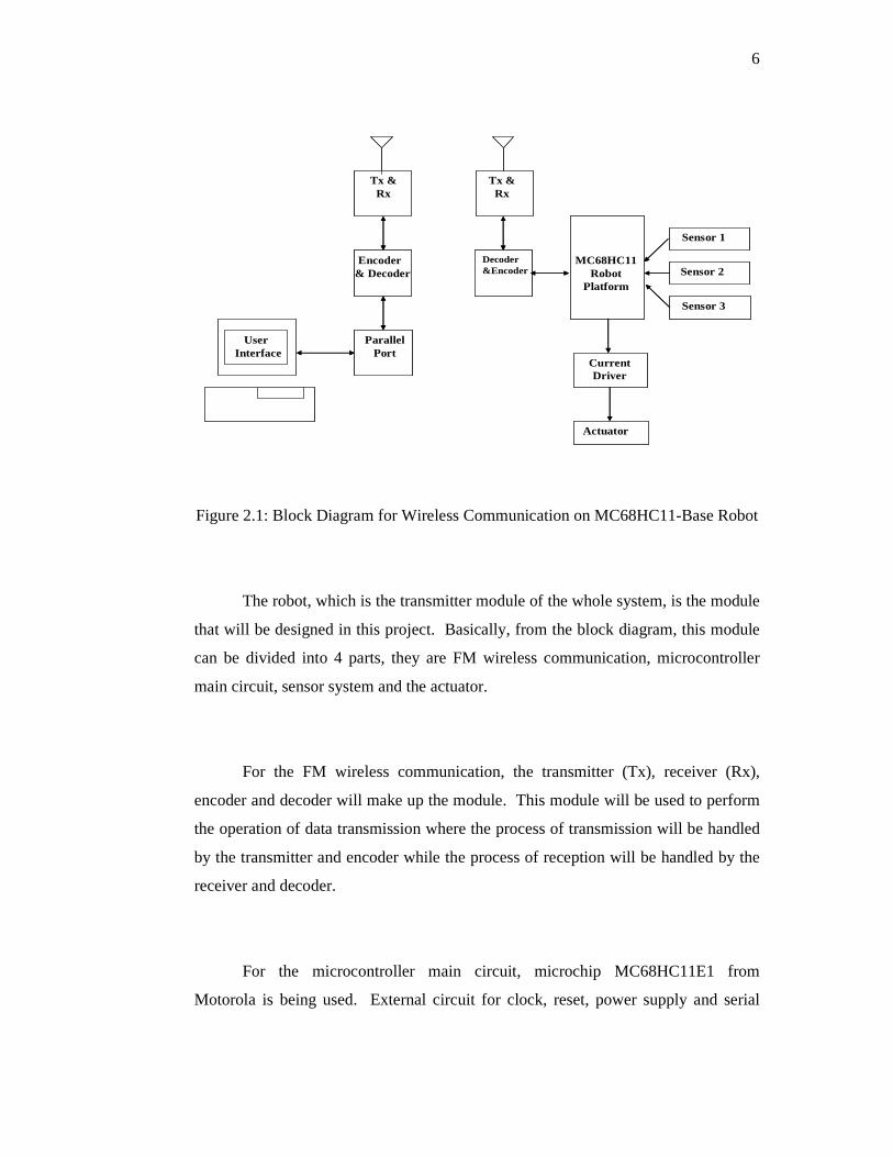
Figure 2.1 is a simple block diagram of the system. Basically, there are two
parts that need to be designed, the PC as the receiver module and the robot as the
transmitter module.
6
UserInterface
ParallelPort
Encoder& Decoder
Tx &Rx
Tx &Rx
Decoder&Encoder
MC68HC11Robot
Platform
Sensor 1
Sensor 2
Sensor 3
CurrentDriver
Actuator
UserInterface
ParallelPort
Encoder& Decoder
Tx &Rx
Tx &Rx
Decoder&Encoder
MC68HC11Robot
Platform
Sensor 1
Sensor 2
Sensor 3
CurrentDriver
Actuator
Figure 2.1: Block Diagram for Wireless Communication on MC68HC11-Base Robot
The robot, which is the transmitter module of the whole system, is the module
that will be designed in this project. Basically, from the block diagram, this module
can be divided into 4 parts, they are FM wireless communication, microcontroller
main circuit, sensor system and the actuator.
For the FM wireless communication, the transmitter (Tx), receiver (Rx),
encoder and decoder will make up the module. This module will be used to perform
the operation of data transmission where the process of transmission will be handled
by the transmitter and encoder while the process of reception will be handled by the
receiver and decoder.
For the microcontroller main circuit, microchip MC68HC11E1 from
Motorola is being used. External circuit for clock, reset, power supply and serial

7
communication is being constructed together with the MC68HC11E1 to be a
complete microcontroller main circuit.
The sensors module consists of four types of different sensors that are light
sensors, temperature sensor, bumper switches and Infra Red Proximity Detector
(IRPD). The light sensors and temperature sensor are used to scout the light and heat
intensity respectively while the bumper switches and IRPD are used to detect the
obstacle.
The L293D motor driver, TAMIYA gear box, and two DC motors will make
up the actuator part. This part is important for the motion of the robot.
2.2 Controlling the Robot Motion
Two bi-directional DC motors are utilized to drive the mobile robot in this
project. These motors are configured in such a way that the robot will be able to
move forward, reverse and spins right or left on its axis. Controlling DC motors is
tricky. If continuous high logic is provided to DC motor, it will drive at maximum
speed. This situation is not suitable for the robot as it needs to monitor its
surroundings.

8
To overcome this problem, a constant stream of pulses is generated at a duty
cycle of 50% to drive the DC motors. This would allow the motors to move at
desired speed. The duty cycle supplies high and low logic alternately at the same
interval as shown in figure 2.2.
Figure 2.2: Pulses with different period
The period of the pulse is calculated to ensure that each pulse provides torque
to move the motors. If the period is small, it would not drive the motor. Similarly, if
the period is too long, it would effect in jinking.
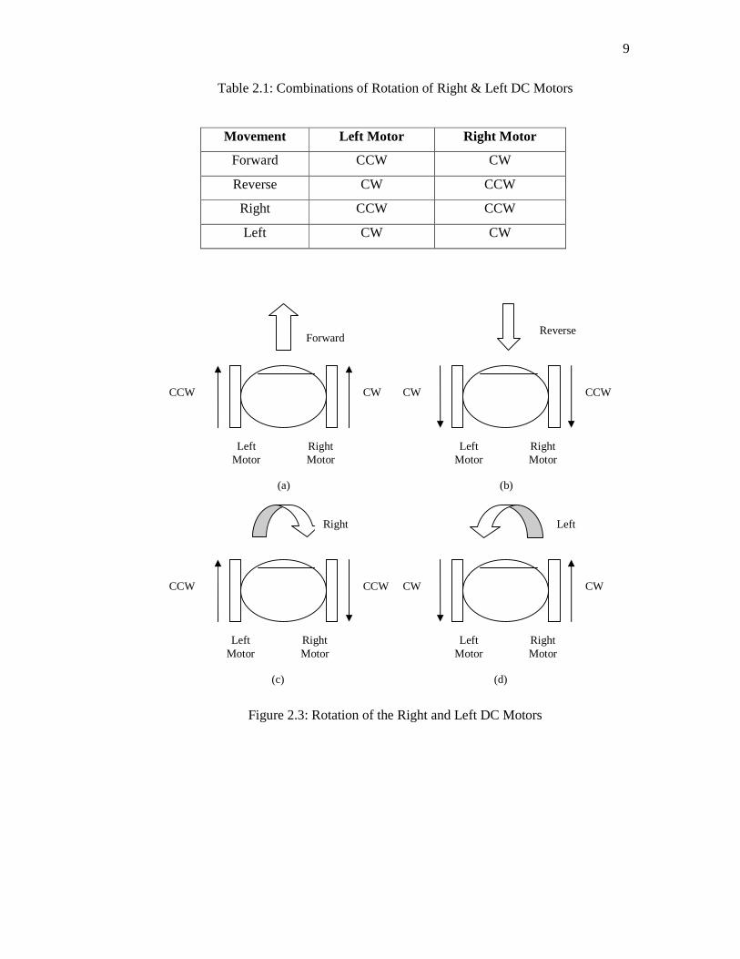
Four configurations of motor rotations are defined to move the robot forward,
reverse and spin right or left. Table 2.1 shows the configurations to move the robot
in four different directions. Figure 2.3 illustrates the four combinations of the
rotation of both the DC motors.
9
Table 2.1: Combinations of Rotation of Right & Left DC Motors
Movement Left Motor Right Motor
Forward CCW CW
Reverse CW CCW
Right CCW CCW
Left CW CW
Figure 2.3: Rotation of the Right and Left DC Motors
Left Motor
Right Motor
Left Motor
Right Motor
Left Motor
Right Motor
Left Motor
Right Motor
Forward Reverse
Right Left
CCW CCW
CCW CCW
CW CW
CW CW
(a)
(c)
(b)
(d)
10
2.3 ODOMETRY
A common technique used to implement odometry in robot is by using the
wheel encoder. There are various kinds of wheel encoders that can be built.
However, two popular methods are reading infrared light reflection from a black and
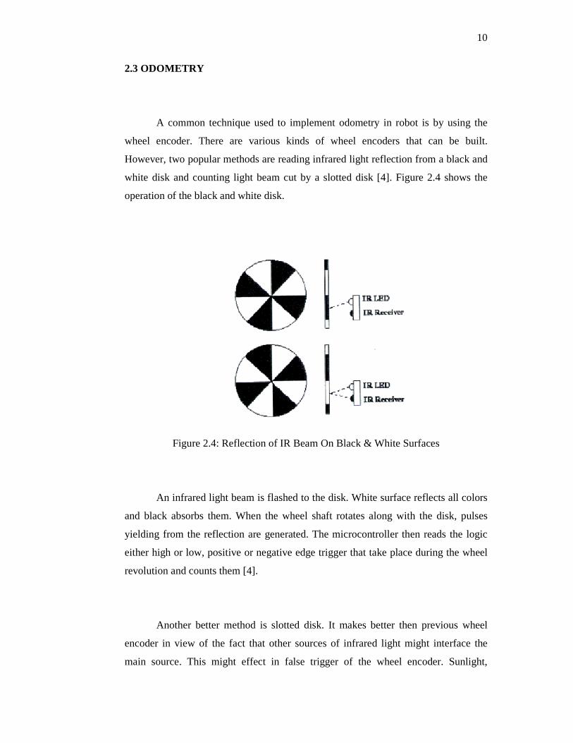
white disk and counting light beam cut by a slotted disk [4]. Figure 2.4 shows the
operation of the black and white disk.
Figure 2.4: Reflection of IR Beam On Black & White Surfaces
An infrared light beam is flashed to the disk. White surface reflects all colors
and black absorbs them. When the wheel shaft rotates along with the disk, pulses
yielding from the reflection are generated. The microcontroller then reads the logic
either high or low, positive or negative edge trigger that take place during the wheel
revolution and counts them [4].
Another better method is slotted disk. It makes better then previous wheel
encoder in view of the fact that other sources of infrared light might interface the
main source. This might effect in false trigger of the wheel encoder. Sunlight,

11
consisting of various frequencies of light, is among the interference. Slotted disk
consists of tiny several equivalent distanced thin slots allowing a phototransistor to
pick up light beam from the source when a slot exposes the source [4]. Figure 2.5
illustrated the operation of the slotted disk.
Figure 2.5: Position of Slots during and Effects on the Optical Encoder
Counting wheel revolution does not imply 360 degrees angle rotation as one
rotation. One wheel revolution may consist of several rotations at certain degrees
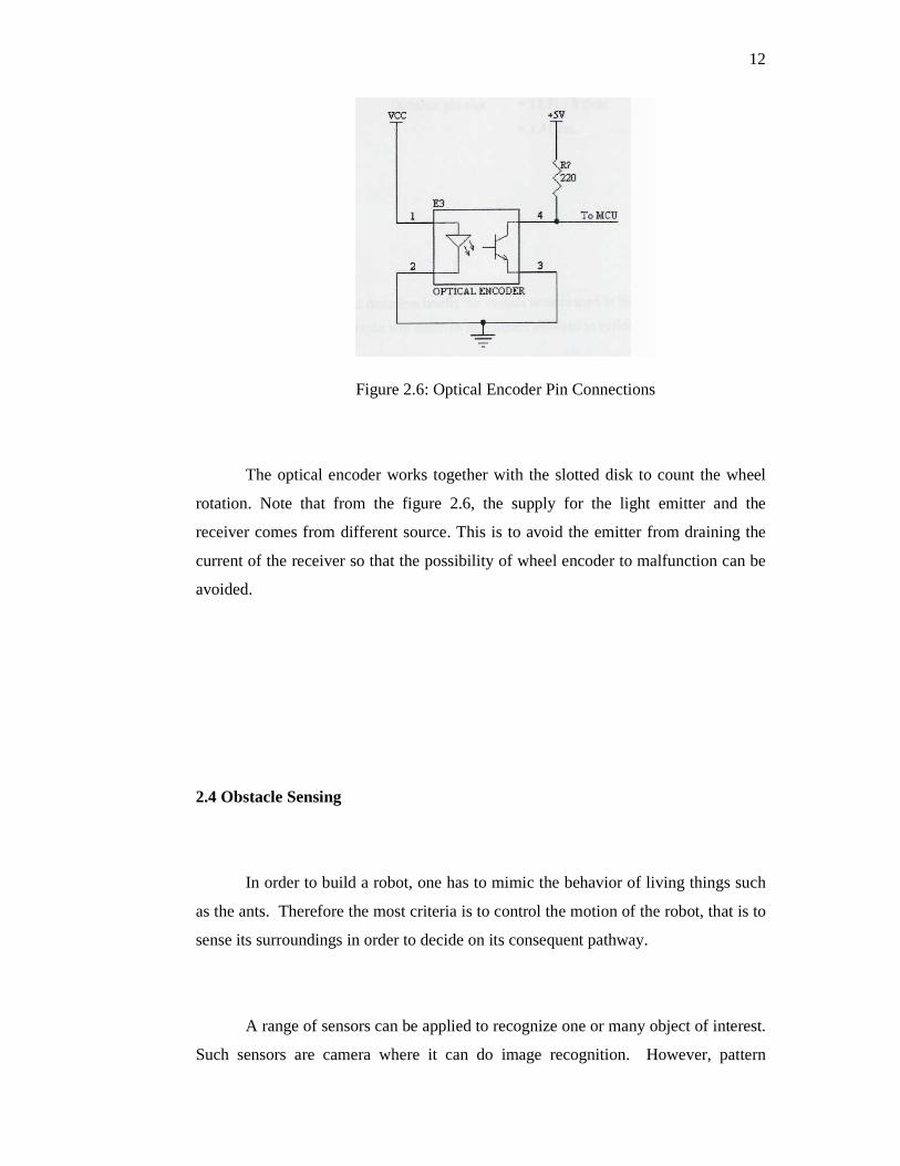
dependent on the number of black and white stripes or slots. Figure 2.6 shows the
schematic of the optical encoder interface.
12
Figure 2.6: Optical Encoder Pin Connections
The optical encoder works together with the slotted disk to count the wheel
rotation. Note that from the figure 2.6, the supply for the light emitter and the
receiver comes from different source. This is to avoid the emitter from draining the
current of the receiver so that the possibility of wheel encoder to malfunction can be
avoided.
2.4 Obstacle Sensing
In order to build a robot, one has to mimic the behavior of living things such
as the ants. Therefore the most criteria is to control the motion of the robot, that is to
sense its surroundings in order to decide on its consequent pathway.
A range of sensors can be applied to recognize one or many object of interest.
Such sensors are camera where it can do image recognition. However, pattern
13
recognition is not the main focus in this project, but it can be implemented when
improvising the robot at a higher level. Sensors are frequently applied in robot to
avoid obstacles. At a higher level mapping obstacles could also be informative as
implemented in this project. Other sensors include radar, sonar, and bumper
switches and infrared obstacle detection, which will be discussed elaborately.
2.4.1 Bumper Whiskers
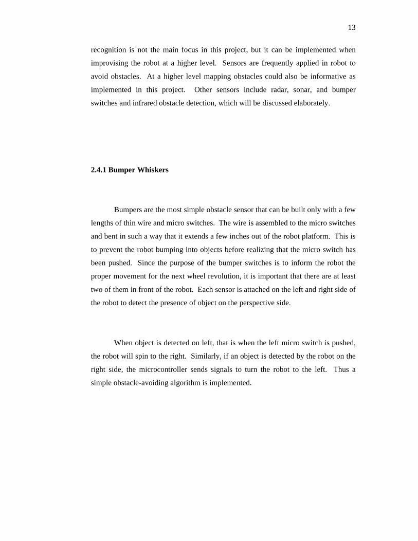
Bumpers are the most simple obstacle sensor that can be built only with a few
lengths of thin wire and micro switches. The wire is assembled to the micro switches
and bent in such a way that it extends a few inches out of the robot platform. This is
to prevent the robot bumping into objects before realizing that the micro switch has
been pushed. Since the purpose of the bumper switches is to inform the robot the
proper movement for the next wheel revolution, it is important that there are at least
two of them in front of the robot. Each sensor is attached on the left and right side of
the robot to detect the presence of object on the perspective side.
When object is detected on left, that is when the left micro switch is pushed,
the robot will spin to the right. Similarly, if an object is detected by the robot on the
right side, the microcontroller sends signals to turn the robot to the left. Thus a
simple obstacle-avoiding algorithm is implemented.
14
2.4.2 Infra Red Proximity Detector (IRPD)
Infra red proximity detector (IRPD) is another detector that can be used to
operate as robot sensor. Unlike the previous detector, IRPD is based on light
reflection. Since the Infra red light is not within the visible light spectrum, it does
not obey all the same properties as visible light [5]. Infrared can pass through certain
types of plastics, colors and some other materials. It reflects off most objects. Even
variables such as texture and reflectivity affect its reliability. There are 2 types of
infra red, that is near infra red, that operates at 800 to 1000nm, and the far infra red
light that is normally used in security systems or night vision goggles and operates
from 2000 to 10000nm.
This type of sensor is called a proximity detector, because it can only detect
an obstacle which is within range of distance. An IRPD works by illuminating in
front of the robot with infra red light. When the light is reflected by an obstacle in
front of the robot, the infra red detector will register that light as an obstacle.
Since there are other sources of infra red light, the frequency of infra red light
used is generated between 35 kHz to 40 kHz. This is because there are very few
sources of infra red lights at these frequencies resulting in less possibilities of
interference. The infra red light modulated at certain frequencies normally work in
pair with a detector equipped with a band pass filter with the same centre frequency.
The advantage of using IRPD is that it makes possible for the robot to detect
an object without bumping into it. However, the IRPD may not be able to detect
object with black surfaces.
In designing the IRPD, one might place two pairs of infrared LED and
infrared detectors, which is each pair on each side of the robot for monitoring

15
purposes. Normally in this arrangement, both the left and right infrared LED always
activated. Infra red light spreads out of the LED in many directions flooding the
front of the robot. In this situation, both the detector receives infrared light. To
overcome this problem, instead of always turning on both infrared LED, either one is
turned on when checking the corresponding side of the robot for objects. This will
also help to saving the power supply and possible to detect both infrared LED’s
reflection signal by using only one infrared detector. In other words, not only that
the microcontroller had to assign one input pins for the infrared detectors, the
microcontroller must also spare two output pins to control both the infrared LED.
2.5 Communication Protocol
In general, the lower nibble is transmitted and it is followed by the higher
nibble. Nevertheless, there should be a mechanism to distinguish between both
nibbles in order to retrieve a byte as it is transmitted.
For this project, the robot and PC communicate bi-directionally as both are
able to send and receive data. Due to cost and time limitation, two pairs of
transmitter and receiver module are applied in order to provide a half duplex
communication. Since both transmitter modules are operating at the same frequency
carrier, it allows only one transmitter to transmit at one time. If both of them are
transmitting simultaneously, data will be corrupted due to data collision.
In order to overcome the collision problem and identify nibbles, a simple
non-standardized communication protocol is implemented. Header or trailer is used
to distinguish the higher nibble from the lower nibble.

16
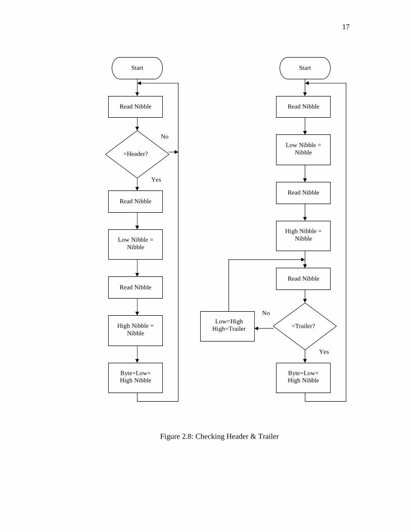
Figure 2.7 shows how a header or trailer can be appended to a byte before
transmitting. The size of the header or trailer is 4 bits length. If header is
implemented, receiver will scan for the header before reading the low nibble
followed by the higher nibble. If received nibble matches a specified header, the
following nibbles are saved as a byte in a variable. Otherwise, the nibble will be
discarded and the following nibble repeats the same process. Figure 2.8 illustrates
this process.
Figure 2.7: Appending Header & Trailer to a Byte
Byte
Byte
Header Low Nibble High Nibble
Low Nibble High Nibble Trailer
(a)
(b)
17
Figure 2.8: Checking Header & Trailer
Start
Read Nibble
=Header?
Read Nibble
Low Nibble = Nibble
Read Nibble
Byte=Low+ High Nibble
High Nibble = Nibble
Start
Read Nibble
=Trailer?
Read Nibble
Byte=Low+ High Nibble
Low Nibble = Nibble
High Nibble = Nibble
Read Nibble
Low=High High=Trailer
Yes
Yes
No
No
18
On the contrary, if the trailer technique is implemented, the first nibble
received is saved as the low nibble, and the second is considered as the higher nibble.
The third nibble will be compared to the trailer. If they match, the high and low
nibble will be combined to form a byte. Otherwise, the previous low nibble will be
saved as the low nibble, and the third nibble received is saved as the high nibble.
The consequent nibble accepted will be compared to the trailer again and this
procedure is repeated until the trailer matches a specified figure.
Establishing a half-duplex communication is a more complex task than
implementing a full-duplex. Either side of the system must be assigned as master or
slave. Normally, the master device initiates the transmission by sending data. The
slave waits until the master terminates transmission before it can respond to the
master device. Generally the master device gives command or request for data. A
valid transmission mechanism is implemented to recognize the terminating
transmission of the master device.
Delay between each transfer of the data of the master device is important to
ensure correct data is received. This is to prevent both master and slave device
transmits at the same instance. The amount of delay applied is determined by several
tests carried out.
There are two type of protocol communication that is unacknowledged and
acknowledged. Each one has its own advantages and drawbacks. Normally, for
short blocks of data, the unacknowledged protocol is preferred. It is fast thus the
real-time data are updated at its best performance. However the protocols are unable
to recover lost data. Also it only works best if the data transferred is a single real-
time data. In this protocol, the master device only receives data that are transmitted
continuously by the slave device. This can be drawn from the previous Figure 2.8.
19
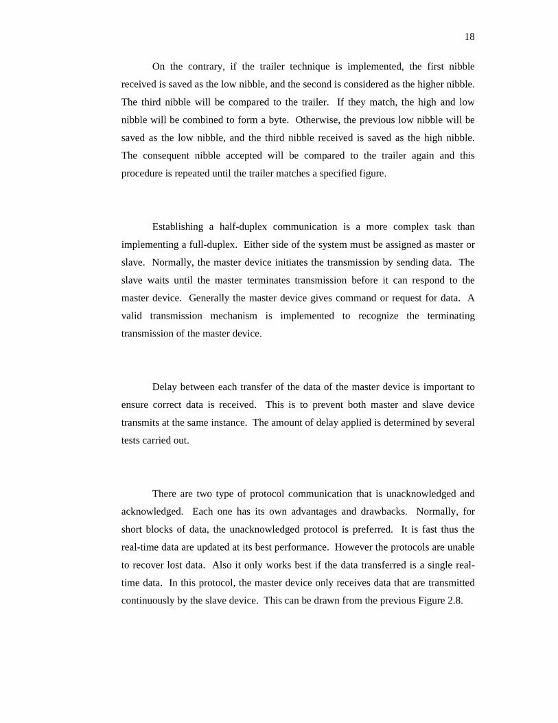
For transferring several data in blocks, it is most appropriate if the receiver
could recognize which data belongs to which variable. To apply this, the
acknowledged protocol is used. For example if the master device sends request data
number 2, then the slave will reply data 2 along with a header or trailer number 2.
This way, the master device would be able to ensure that the data it receives is the
data it requests. In this mode, the master device would also be able to detect data lost
or damaged and retrieve it again. Figure 2.9 demonstrates the flow of the
acknowledged communication protocol for the slave device.
Figure 2.9: Acknowledged Slave Device Algorithm
Start
Receive Transmission?
N = Command/Re
quest?
Fetch Data N
Transmit Data N
Execute Command N
No
Yes

20
2.6 Overall Operation
This project, as a whole, demonstrates the important of PC-Robot
communication. Implementing wireless communication is a complex task and
depends on the hardware architecture applied to achieve the objectives of this
project. Due to the limitation confronted, the following algorithm is best applied to
ensure the aims of this project are attained.
In this project, the PC plays the role of the master device while the robot as
the slave. Therefore the robot waits for the transmission from the PC to decide its
proper action either it be command or request data. When the robot receives data, it
translates and performs as it is programmed. As initial stage, the PC has to send data
to inform the robot to operate either autonomous or manual control.
In autonomous mode, the robot runs the autonomous algorithm that defined
in Chapter 4. For each motion, the robot will read the IRPD and transmits both the
IRPD and bumper data making up two bytes. In this case, the PC waits for data
transmitted by the robot. This mode demonstrates the implementation of
unacknowledged protocol communication explained earlier and this is the most
suitable protocol to be applied in view of the fact that only two bytes of data are
being transferred.
On the other hand, the manual mode of operation implements the
acknowledged protocol communication. The robot remains in its static position until
the PC sends command or request data. Upon receiving command data, the robot
moves as it is commanded. When the robot recognizes the requests data
transmission, it fetches the data corresponding to the requests data and transmit them
together back to the PC.
CHAPTER 3
HARDWARE DESIGN
3.1 Robot System
Robots require a microprocessor to calculate logical and arithmetic
operations. In addition, several input and output ports must be attached to the robot
to read parameters from the surrounding for pre-programmed task. For these
reasons, microcontroller is the best solution for this task. There are various
microcontrollers that can be found with various features. However, for this
particular robot, the microcontroller must be able to control a two DC motor via
pulse generation, scan various sensors. In addition, the microcontroller can transmit
and receive data to and from the PC via a FM wireless link.
22
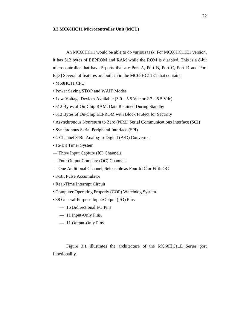
3.2 MC68HC11 Microcontroller Unit (MCU)
An MC68HC11 would be able to do various task. For MC68HC11E1 version,
it has 512 bytes of EEPROM and RAM while the ROM is disabled. This is a 8-bit
microcontroller that have 5 ports that are Port A, Port B, Port C, Port D and Port
E.[3] Several of features are built-in in the MC68HC11E1 that contain:
• M68HC11 CPU
• Power Saving STOP and WAIT Modes
• Low-Voltage Devices Available (3.0 – 5.5 Vdc or 2.7 – 5.5 Vdc)
• 512 Bytes of On-Chip RAM, Data Retained During Standby
• 512 Bytes of On-Chip EEPROM with Block Protect for Security
• Asynchronous Nonreturn to Zero (NRZ) Serial Communications Interface (SCI)
• Synchronous Serial Peripheral Interface (SPI)
• 4-Channel 8-Bit Analog-to-Digital (A/D) Converter
• 16-Bit Timer System
— Three Input Capture (IC) Channels
— Four Output Compare (OC) Channels
— One Additional Channel, Selectable as Fourth IC or Fifth OC
• 8-Bit Pulse Accumulator
• Real-Time Interrupt Circuit
• Computer Operating Properly (COP) Watchdog System
• 38 General-Purpose Input/Output (I/O) Pins
— 16 Bidirectional I/O Pins
— 11 Input-Only Pins.
— 11 Output-Only Pins.
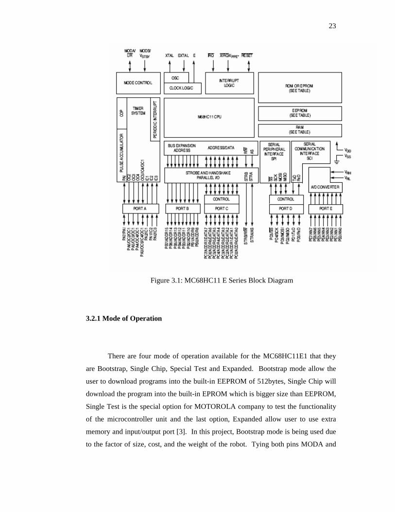
Figure 3.1 illustrates the architecture of the MC68HC11E Series port
functionality.
23
Figure 3.1: MC68HC11 E Series Block Diagram
3.2.1 Mode of Operation
There are four mode of operation available for the MC68HC11E1 that they
are Bootstrap, Single Chip, Special Test and Expanded. Bootstrap mode allow the
user to download programs into the built-in EEPROM of 512bytes, Single Chip will
download the program into the built-in EPROM which is bigger size than EEPROM,
Single Test is the special option for MOTOROLA company to test the functionality
of the microcontroller unit and the last option, Expanded allow user to use extra
memory and input/output port [3]. In this project, Bootstrap mode is being used due
to the factor of size, cost, and the weight of the robot. Tying both pins MODA and

24
MODB to ground activates this mode of operation. Bootstrap mode allows the user
to download programs into the MCU EEPROM of 512 bytes.
3.2.2 Bootstrap Mode Circuit
Figure 3.2 is the basic circuitry for operating the MCU in bootstrap mode
with the connection with MAX 233 for the serial communication. MAX 233 is used
for the RS-232 line to connect between PC and the MCU so that the programs from
PC can be loaded into the MCU EEPROM. The crystal for this set-up is 8.0 MHz
yielding an E-clock of 2 MHz.
Figure 3.2: MC68HC11 E1 Bootstrap Mode Basic Circuit