
Method of Evolutionary Designing of FPGA-based Controllerspe.org.pl/articles/2016/7/38.pdf ·...
6
174 PRZEGLĄD ELEKTROTECHNICZNY, ISSN 0033-2097, R. 92 NR 7/2016 Andrzej PRZYBYŁ 1 , Jacek SZCZYPTA 1 Częstochowa University of Technology (1) doi:10.15199/48.2016.07.38 Method of Evolutionary Designing of FPGA-based Controllers Abstract. Controller design is a difficult and time consuming process. Moreover, high implementation accuracy of theoretically developed control algorithm causes high computational complexity and may result in inability of control system to work with selected time step. Short time step is often a necessary condition of correctness of control algorithm and finally of control system. These requirements may be fulfilled by use of the field programmable gate array (FPGA) as a implementation platform. However, in many cases designed controller is sensitive to inaccuracy due to limited resolution of input and output signals as well as of digital word used in implementation. All of these limitations should be taken into consideration in design stage. In this paper is proposed a method based on an evolutionary algorithm which takes into account mentioned limitations. As a result the process of controller design is performed easier and faster. Streszczenie. Projektowanie regulatora jest trudnym i czasochłonnym procesem. Ponadto implementacja opracowanego teoretycznie algorytmu sterowania niejednokrotnie skutkuje wysoką złożonością obliczeniową. Może to skutkować brakiem możliwości pracy systemu sterowania z zadanym krokiem czasowym. Oprócz wspomnianych zjawisk występują problemy związane z rozdzielczością sygnałów wejściowych i wyjściowych jak i słowa cyfrowego użytego w implementacji realizowanej w na przykład układach programowalnych FPGA. Aby powstający system działał prawidłowo wszystkie te ograniczenia powinny być uwzględnione już na etapie projektowania. W artykule przedstawiona została metoda projektowania systemu regulacji bazująca na algorytmie ewolucyjnym. Metoda ta uwzględnia wspomniane ograniczenia oraz czyni trudny i czasochłonny proces projektowania regulatora łatwiejszym i szybszym. (Metoda ewolucyjnego projektowania regulatorów bazujących na FPGA) Keywords: evolutionary algorithm, optimization, FPGA, state space variables. Słowa kluczowe: algorytm ewolucyjny, optymalizacja, FPGA, zmienne stanu. Introduction Deployment of an automatic control system is a process which requires taking into account several interacting factors. In particular, the following steps have to be taken: indication of signals that have to be measured, selection of the controller structure, tuning of the controller parameters, implementation in target hardware platform with fulfillment of requirements of real-time work. As a part of the last step of presented activities, an in-depth analysis has to be performed. The analysis is related to: computational complexity and setting of proper value of time step for control algorithm, adverse influence of measurement noise and discretization of measurement signals (caused by measurement instruments) and control signals (caused by actuator devices), adverse influence of implementation in digital system based on finite-length word. Despite that the control system deploy path is quite clear and typical, it is important to note that the path introduces significant inconvenience. Such inconvenience may happen, and it happens quite often, when the implementation is too expensive or even impossible in available hardware. This is because, for example, the designed controller can be very sensitive to inaccuracy due to limited resolution of digital word used in implementation on target platform. Similarly, adverse influence on the controller is caused by limited resolution of digital signals coming from sensors or signals controlling actuator elements. In particular, it is important to mention that implementation of control system based on floating-point numbers is usually inefficient or even impossible. Instead of floating point, implementation based on fixed-point should be chosen and properly designed scaling related to range of processed values should be performed. Implementation of control algorithm in digital system is always a result of compromise between speed and accuracy. Theoretically developed control algorithm causes in some cases high computational complexity and may result in inability to work in real-time with selected time step. This situation, if it is detected in deployment stage, usually causes necessity of redesigning of entire controller and additional expenses. In this paper is proposed a method in which constrains related to implementation in target system are taken into account in the first steps of control system design. Thus, it is possible to achieve precise mapping of theoretically developed control algorithm and avoid problems at the implementation stage and additional expenses. In the literature there are presented various approaches to design of control system. Typical approaches are as follows: controllers based on the combination of linear correction terms, e.g. PID controllers (optionally with gain scheduling algorithm, with feed-forward path or with additional low-pass filters [1]), state feedback controllers, nonlinear controllers based on computational intelligence and hybrid controllers, in which are combined approaches from other groups. However, in practice PID controllers are used the most often. It is a result of widespread knowledge of how they work and their relatively simple implementation in a microprocessor-based control systems. Researches performed so far on designing of control system were extended in this paper by taking into account the aspect of limited accuracy related to implementation in the field programmable gate array (FPGA). Implementation in FPGA gives a benefit of implementation of even very complex controller which will operate with a very short reaction time. Short reaction time is often a necessary condition of correctness of control system. Moreover, method proposed in this paper can be used in future not only for designing of control systems but also of hardware emulators of dynamic objects [2,3-7]. Such emulators are usually used in a development process of a complex controller of a machine or an industrial process. It is important to point out that controller structure selection and parameters tuning is a difficult and time consuming process. Sometimes, in order to obtain a better control quality engineer, basing on his experience, has to modify the controller structure. Modification of the controller structure, usually performed by means of trial and error method, causes the process of controller design much more difficult. In this paper is presented a method of designing of controller for a permanent magnet synchronous motor (PMSM) based servo-drive (Fig. 1). The method takes into
Transcript of Method of Evolutionary Designing of FPGA-based Controllerspe.org.pl/articles/2016/7/38.pdf ·...

174 PRZEGLĄD ELEKTROTECHNICZNY, ISSN 0033-2097, R. 92 NR 7/2016
Andrzej PRZYBYŁ1, Jacek SZCZYPTA1
Częstochowa University of Technology (1)
doi:10.15199/48.2016.07.38
Method of Evolutionary Designing of FPGA-based Controllers
Abstract. Controller design is a difficult and time consuming process. Moreover, high implementation accuracy of theoretically developed control algorithm causes high computational complexity and may result in inability of control system to work with selected time step. Short time step is often a necessary condition of correctness of control algorithm and finally of control system. These requirements may be fulfilled by use of the field programmable gate array (FPGA) as a implementation platform. However, in many cases designed controller is sensitive to inaccuracy due to limited resolution of input and output signals as well as of digital word used in implementation. All of these limitations should be taken into consideration in design stage. In this paper is proposed a method based on an evolutionary algorithm which takes into account mentioned limitations. As a result the process of controller design is performed easier and faster. Streszczenie. Projektowanie regulatora jest trudnym i czasochłonnym procesem. Ponadto implementacja opracowanego teoretycznie algorytmu sterowania niejednokrotnie skutkuje wysoką złożonością obliczeniową. Może to skutkować brakiem możliwości pracy systemu sterowania z zadanym krokiem czasowym. Oprócz wspomnianych zjawisk występują problemy związane z rozdzielczością sygnałów wejściowych i wyjściowych jak i słowa cyfrowego użytego w implementacji realizowanej w na przykład układach programowalnych FPGA. Aby powstający system działał prawidłowo wszystkie te ograniczenia powinny być uwzględnione już na etapie projektowania. W artykule przedstawiona została metoda projektowania systemu regulacji bazująca na algorytmie ewolucyjnym. Metoda ta uwzględnia wspomniane ograniczenia oraz czyni trudny i czasochłonny proces projektowania regulatora łatwiejszym i szybszym. (Metoda ewolucyjnego projektowania regulatorów bazujących na FPGA) Keywords: evolutionary algorithm, optimization, FPGA, state space variables. Słowa kluczowe: algorytm ewolucyjny, optymalizacja, FPGA, zmienne stanu. Introduction
Deployment of an automatic control system is a process which requires taking into account several interacting factors. In particular, the following steps have to be taken: indication of signals that have to be measured, selection of the controller structure, tuning of the controller parameters, implementation in target hardware platform with
fulfillment of requirements of real-time work. As a part of the last step of presented activities, an in-depth analysis has to be performed. The analysis is related to: computational complexity and setting of proper value
of time step for control algorithm, adverse influence of measurement noise and
discretization of measurement signals (caused by measurement instruments) and control signals (caused by actuator devices),
adverse influence of implementation in digital system based on finite-length word.
Despite that the control system deploy path is quite clear and typical, it is important to note that the path introduces significant inconvenience. Such inconvenience may happen, and it happens quite often, when the implementation is too expensive or even impossible in available hardware. This is because, for example, the designed controller can be very sensitive to inaccuracy due to limited resolution of digital word used in implementation on target platform. Similarly, adverse influence on the controller is caused by limited resolution of digital signals coming from sensors or signals controlling actuator elements. In particular, it is important to mention that implementation of control system based on floating-point numbers is usually inefficient or even impossible. Instead of floating point, implementation based on fixed-point should be chosen and properly designed scaling related to range of processed values should be performed.
Implementation of control algorithm in digital system is always a result of compromise between speed and accuracy. Theoretically developed control algorithm causes in some cases high computational complexity and may result in inability to work in real-time with selected time step. This situation, if it is detected in deployment stage, usually
causes necessity of redesigning of entire controller and additional expenses.
In this paper is proposed a method in which constrains related to implementation in target system are taken into account in the first steps of control system design. Thus, it is possible to achieve precise mapping of theoretically developed control algorithm and avoid problems at the implementation stage and additional expenses.
In the literature there are presented various approaches to design of control system. Typical approaches are as follows: controllers based on the combination of linear correction terms, e.g. PID controllers (optionally with gain scheduling algorithm, with feed-forward path or with additional low-pass filters [1]), state feedback controllers, nonlinear controllers based on computational intelligence and hybrid controllers, in which are combined approaches from other groups. However, in practice PID controllers are used the most often. It is a result of widespread knowledge of how they work and their relatively simple implementation in a microprocessor-based control systems.
Researches performed so far on designing of control system were extended in this paper by taking into account the aspect of limited accuracy related to implementation in the field programmable gate array (FPGA). Implementation in FPGA gives a benefit of implementation of even very complex controller which will operate with a very short reaction time. Short reaction time is often a necessary condition of correctness of control system. Moreover, method proposed in this paper can be used in future not only for designing of control systems but also of hardware emulators of dynamic objects [2,3-7]. Such emulators are usually used in a development process of a complex controller of a machine or an industrial process.
It is important to point out that controller structure selection and parameters tuning is a difficult and time consuming process. Sometimes, in order to obtain a better control quality engineer, basing on his experience, has to modify the controller structure. Modification of the controller structure, usually performed by means of trial and error method, causes the process of controller design much more difficult. In this paper is presented a method of designing of controller for a permanent magnet synchronous motor (PMSM) based servo-drive (Fig. 1). The method takes into

PRZEGLĄD ELEKTROTECHNICZNY, ISSN 0033-2097, R. 92 NR 7/2016 175
CBk
b)
+
+
++
1-a
+a
+1z
+
+
CB 3CB 2 uq*
ud*
+ ++ ++
--+
-CB 1
a)
ff 2
ff 4
iq
ff 1
CB4+-
id
iq
*
id*=0
ff 3
1zq
1
q2
q0
1z
e k ykf k
f k-1
f k-2
uVelocityControl
-PositionControl
+ Current,qControl
uPark Clarke
Inverter
PMSM
Current,dControl
Park Clarke
ddt
u
d,q
d,q
a,b,c
a,b,c
u
i
i
u u
Controller
- -
-
+ +
+
+ +
Encoder
u
*
*
*
iqid
q
d
ib
ia
a b c
id*
-1 -1
K
account additional signals in the controller structure as presented in Fig. 1 using dashed line.
Fig. 1. Control system of a typical PMSM based servo-drive.
The method is motivated by industrial use of the controllers equipped with different combinations of additional signals and coupling paths, as it was shown in [8]. The novelty of the method presented in this paper allows to design a controller which is well suited to hardware implementation in the FPGA. The method allows to design controller automatically by means of evolutionary algorithm [9-11].
Assumptions related to the controller design
The controller that is to be designed is a third order controller (Fig. 2.a).
Fig. 2. Internal structure of: a) initial controller, b) controller’s configurable block (CB).
In the controller, despite the position (), velocity ()
and current (id, iq) loops there are also included two paths for reference signals (,) and three coupling paths with controller internal signals to improve the control dynamics.
The proposed controller (Fig. 2.a) is composed of four processing blocks. Everyone is called configurable block (CB) with internal structure shown in Fig. 2.b. CB consists of three elements: the first order infinite impulse response
(IIR) input filter defined by one parameter (a), the PID controller in the serial form [12] defined by three parameters (q0,q1,q2) and the anti-wind-up mechanism. In such a way several CBs can constitute the whole controller or model a dynamic object [2].
The additional reference signals (, ) and controller inner signals constitute separate feed-forward paths. On some feed-forward paths is a processing element ffK, which is performing multiplication by gain factor ffK.
In the controller are processed: reference signals (,,), model signals (, , id, iq) and internal signals of the controller (CB1 input signal and CB1 output signal). The meaning of the signals used by the controller is presented as follows: is reference value of angular position of the rotor flux, is reference value of its angular velocity, is reference value of its angular acceleration, is its angular position, is its angular velocity, the id, iq are direct and quadrature components of a vector representing an electrical currents in the motor windings, respectively, the ud, uq are direct and quadrature components of electrical voltages applied to the motor terminals.
Subsequent CBs and feed-forward paths are sequentially executed in the order given by direction of processing of input signals.
Assumptions related to the controller implementation
The controller is to be implemented in the Spartan 6 FPGA from Xilinx [13] by means of Altium Designer software.
Hardware resources of the FPGA despite the universal programmable logic consist of dedicated DSP slices. Usage of DSP slices allows to achieve high operating efficiency and to reduce utilization of universal resources. However, the assumptions regarding resolution of dedicated blocks made by the FPGA manufacturer are not always relevant and DSP slices don’t always provide sufficient accuracy in specific applications.
DSP slice like DSP48A1 [13] is a fixed-point adding-multiplying block, which is operating on 18-bit long digital word, which in many applications provide sufficient accuracy under the condition of proper designing of control algorithm. Such condition was fulfilled during design of controller presented in this paper.
Main difficulty, which has to be overcome during design of controller tailored to implementation in fixed-point digital system, is different range of consecutively processed values. Necessary care about proper range and scaling can be significantly reduced if there will be used signals relatively referred to their base values. However, it is possible to change operating range of every processed signal to normalized range: <-1...1> represented in binary system as an e.g. fixed-point „1.17” values. Thus, it is possible to reduce daunting operation set to scaling of input and output values of entire system, while operations inside of digital system are working in normalized range. Such conversion limits hardware resource usage and reduces delay of data processing.
From the point of view of the hardware implementation the CB is the most important building block of the controller. Their performance has a direct impact on the performance of the entire controller. Thus, in order to obtain high controller efficiency, the CB was designed to process the internal signals fully in parallel. Implementation of the CB is presented in Fig. 3 .
For the comfort and clarity of description of elements used in the implementation a diagram form was chosen. In the implementation following types of elements were used: ADDER, MULTIPLIER, REGISTER and LIMITER. The

176 PRZEGLĄD ELEKTROTECHNICZNY, ISSN 0033-2097, R. 92 NR 7/2016
types were derived from the library of Altium Designer. The elements can work with digital word of definable width.
Processing inside CB is performed as follows. First, input of a filter (INPUT) is set in a form of 18-bit fixed-point normalized word. Second, the filtration of input value is performed using an algorithm of the first order IIR filter by means of two multipliers (MULTIPLIER_1 and MULTIPLIER_2) and one adder (ADDER_1). Third, storing of filter output value (ADDER_1) is performed by two registers (REGISTER_1 and REGISTER_2) in a way that, previous value of filter output is stored in REGISTER_1 and previous value stored in REGISTER_1 is stored in REGISTER_2. Thus, in two registers (REGISTER_1 and
REGISTER_2) is stored filter output value from two previous time steps. Fourth, to obtain PID controller the values of filter output and stored in REGISTER_1 and REGISTER_2 are multiplied by the three coefficients (q0,q1,q2)(Fig. 2.b) (P_Q0, P_Q1, P_Q2)(Fig. 3) respectively, and then summed by two adders (ADDER_4 and ADDER_3) and integrated (ADDER_2 and REGISTER_3) according to the PID controller in serial form. The fifth, limitation of PID output at a anti-wind-up level is performed (LIMITER). Finally, the result is transmitted further (OUTPUT) as a 18-bit fixed-point normalized word.
Fig. 3. Implementation of the controller’s configurable block (CB).
The main part of the controller structure (Fig. 2.a) was implemented on the Xilinx Spartan6 XC6SLX45-3C FPGA device. The utilization of FPGA resources required for the implementation is show in Table 1.
Table 1. FPGA resources required for controller implementation
Resource name DSP48A1 Registers LUTs Controller (CB) 24 (5) 867 (72) 1200 (261) Total available 58 54576 27288 Device utilization [%] 41 2 4
The timing analysis indicates that the controller is able
to work with clock frequency of 32.8 MHz, while the reaction time is equal to 5 clock cycles, i.e. about 150ns. As a result the achieved performance is much higher than the processor-based implementations. However, it must be noted that the data shown in Table 1 presents the performance of the controller show in Fig. 2 only. In particular, there have not been taken into account the Clarke and Park transformations or speed calculation of parts necessary to build complete controller structure shown in Fig. 1. However, it was not a goal of the paper.
The results obtained indicate that the method allows to achieve high controller performance and low consumption of FPGA resources. Therefore, the method can be useful to design of controllers of different types, not only of the PMSM servo-drive. In particular, it is suitable to implement control systems that require very short reaction time. Method of Evolutionary Designing of Controllers
As it was mentioned in the introduction, the paper proposes the method of automatic controller design by
means of evolutionary algorithm. In this method, entire controller (with its structure and parameters) is coded in a
single chromosome chX .
Chromosome chX is described as follows:
(1) par red,ch ch chX X X ,
where parchX is a chromosome coding CB’s parameters
(Fig. 2.b), while redchX is a chromosome coding existence of
CB’s parameters. It is important to note that every
parameter is coded in parchX and in red
chX , such redundancy
does not lead to a contradiction, but speeds up the search.
Chromosome parchX is described as follows:
(2) par par par par,1 ,2 ,, , ,ch ch ch ch LX X X X
where ch=1,..,Ch denotes index of the chromosome in the population, Ch denotes a number of chromosomes in the
population, L denotes length of the chromosome parchX .
Chromosome parchX is described as follows:
(3) par 1 1 1 1 2 2 2 2 1 4, , , , , , , , , , ,ch P I D P I D K Ka K K T a K K T ff f X ,
where 1 1 1 1 2 2 2 2 1 4, , , , , , , , , , ,P I D P I D K Ka K K T a K K T ff ff denote
values of control system parameters. The set of four
parameters , , , kPkk
I Dka K K T defines the internal structure of

PRZEGLĄD ELEKTROTECHNICZNY, ISSN 0033-2097, R. 92 NR 7/2016 177
k-th CB block (Fig. 2.b), while the ffK value defines the feed-forward gain. Inside each CB block the a parameter denotes parameter of first order infinite-impulse response (IIR) filter, while KP, KI =1/TI and TD are parameters of PID controller structure [8]. These parameters are pre-calculated in a form which is more convenient to implement in digital system with fixed-point arithmetic and are as follows:
(4) 0 1 ,DP R I
R
Tq K T K
T
(5) 1 1 2 ,DP
R
Tq K
T
(6) 2 .DP
R
Tq K
T
Chromosome redchX is described as follows:
(7) red red red red,1 ,2 ,, , , ,ch ch ch ch LX X X X
where every gene red, 0,1ch gX decides if relevant part
is present in controller structure or not, while ch=1,..,Ch, g=1,..,L, denotes gene index in the genome.
The main steps of hybrid genetic-evolutionary algorithm are as follows:
1. Initialize individual’s population. Set maximum number of generations and population size. Set crossover and mutation probability. 2. Evaluate individual’s population. Evaluate the control system coded in every individual. 3.Check hybrid algorithm stop condition. When the algorithm reaches the maximum number of iterations, the algorithm returns information about the best individual in population and exits. Otherwise, goes to step 4. 4.Select individuals for evolutionary operations. 5.Apply crossover operator on Xred. 6.Apply crossover operator on Xpar. 7.Apply mutation operator on Xred. 8.Apply mutation operator on Xpar. 9.Individuals repair. Repair is performed in order to preserve parameters value in acceptable range. 10.Generate offspring population and go to step 2.
For more details see e.g. [9]. Definition of the controlled object
The controlled object is servo-drive with permanent magnet synchronous motor (PMSM) [9,14]. PMSM was modeled in discrete form with time step TS = 5s and represented in state space form in a rotor reference frame as follows:
(8) 1
1
1
21
1 0 0 0 0
0 1 ( ) 0 0 0,
0 1.5 1 0 0 0
0 0 1 0 0 0
SS q S
k kkd ddk km S
S S d kq qqk k
m Lk kS S S
S
R TT i T
L Li iuR T
T T ii iuL L L
F P TT P T TJ J J
T
where k=0,1,…,M denotes sample index related to continuous value of time t=k·TS , M=TE/TS denotes the number of samples through the simulation period TE =2.0 s. All four state variables (id, iq, and ) are available for the controller. The position () is measured directly by position
sensor. The velocity () is estimated on the base of the position. The values of the electrical currents (iq, id) are obtained by transformations of measured phase current values (ia, ib). The transformations are: the Clarke transformation and Park transformation (Fig. 1). TL is a load torque applied to the motor in a form shown in Fig. 4.e. The motor model parameters are: R=1.456 , L=0.008 H, m=0.175 Vs, J=0.06 kgm2, F=0.001 Nms and P=3. Initial values of state variables (id, iq, and ) were set to zero. A shape of the reference signal , with its derivatives and were set as presented in Fig. 4.i, Fig. 4.g and Fig. 4. f. Such reference signals are typical for servo-drive controllers working in a modern high-speed CNC machine tools [15,16].
Controller design
Initial controller structure is presented in Fig. 2. The base values used for the range normalization for
signal , id, iq, ud and uq were set to 6.28 rad, 628 rad/s, 25 A, 25 A, 350V and 350V respectively. The rated parameter of the PMSM motor are as follows: IN = 8.3 A, UN = 200 V, nN = 3000 rpm.
Moreover, limited resolution of position and motor current sensors was the cause of quantization for the input signals ( id, iq) to values 0.628·10-3 rad (10000 pulse per revolution), 0.314 rad/s, 0.01 A, 0.01 A (4096 ADC voltage levels) respectively. Quantization resolution for the output signals (ud and uq) was set to value of 0.07V (5000 levels) because of the limited resolution of the actuator, i.e. pulse width modulation (PWM) module. Quantization of signals processed inside of CB blocks was at the level resulting from fixed-point implementation with 1.17 and 1.35 representations in the FPGA (Fig. 2). Controller cycle time was set to TR=50 s which is mainly a result of limited operating frequency of the actuator.
Range for parameters contained inside each CB block (a, KP, KI, TD) and for feed-forward gain (ffK) was set experimentally. Search ranges were set experimentally as follows: KP=0÷100, KI=0÷2000, TD=0÷0.1, a=0.1÷1 and ffK=0÷2. Basing on the assumption of symmetry of vector control algorithm, the value of the CB4 block parameters was the same as for the CB3 block.
Hybrid evolutionary algorithm
Controller structure selection and parameters tuning was performed using hybrid evolutionary algorithm. Algorithm was executed with the following settings: the number of chromosomes in the population was set to 50, the algorithm was performed for 30000 generations, the crossover probability was set to 0.99, the mutation probability was set to 0.3, the mutation intensity was set to 0.3. The problem of controller design addresses several contradictory issues which have to be taken into account. Thus, the fitness function was defined as follows:
(9) ( ) ,iq
ch ch ch iqch id uq
ch id ch os
MSE w MSE w MSE wff
MSE w os w
X
where MSE MSE MSEiq and MSEid are functions. While w, w, wiq, wid and wos are fitness function weights, which were set experimentally as follows: w=410e6, w=46.1e6, wiq=27.6e3, wid=5.43e6 and wos=0.106e-3.
MSE MSE MSEiq and MSEid are defined as follows:
(10) 2
,
1
( ),
Nch j
chj
eMSE
N
(11) 2
,
1
( ),
Nch j
chj
eMSE
N
178 PRZEGLĄD ELEKTROTECHNICZNY, ISSN 0033-2097, R. 92 NR 7/2016
(12) 2
,
1
( ),
iqNch jiq
chj
eMSE
N
(13) 2
,
1
( ),
idNch jid
chj
eMSE
N
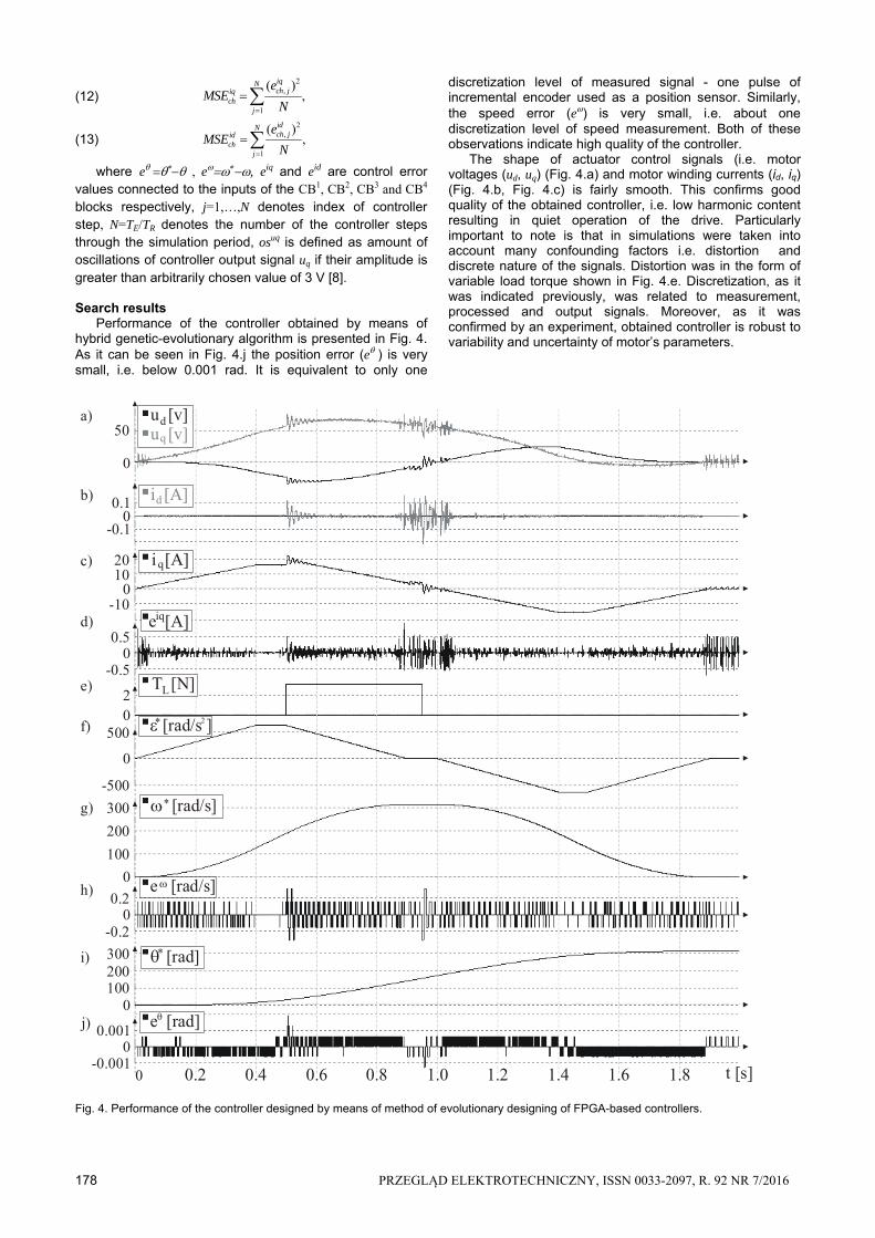
where e , e, eiq and eid are control error values connected to the inputs of the CB1, CB2, CB3 and CB4 blocks respectively, j=1,…,N denotes index of controller step, N=TE/TR denotes the number of the controller steps through the simulation period, osuq is defined as amount of oscillations of controller output signal uq if their amplitude is greater than arbitrarily chosen value of 3 V [8].
Search results
Performance of the controller obtained by means of hybrid genetic-evolutionary algorithm is presented in Fig. 4. As it can be seen in Fig. 4.j the position error (e) is very small, i.e. below 0.001 rad. It is equivalent to only one
discretization level of measured signal - one pulse of incremental encoder used as a position sensor. Similarly, the speed error (e) is very small, i.e. about one discretization level of speed measurement. Both of these observations indicate high quality of the controller.
The shape of actuator control signals (i.e. motor voltages (ud, uq) (Fig. 4.a) and motor winding currents (id, iq) (Fig. 4.b, Fig. 4.c) is fairly smooth. This confirms good quality of the obtained controller, i.e. low harmonic content resulting in quiet operation of the drive. Particularly important to note is that in simulations were taken into account many confounding factors i.e. distortion and discrete nature of the signals. Distortion was in the form of variable load torque shown in Fig. 4.e. Discretization, as it was indicated previously, was related to measurement, processed and output signals. Moreover, as it was confirmed by an experiment, obtained controller is robust to variability and uncertainty of motor’s parameters.
Fig. 4. Performance of the controller designed by means of method of evolutionary designing of FPGA-based controllers.
a)
b)
c)
d)
f)
g)
h)
i)
j)
0 0.2 0.4 0.6 0.8 1.0 1.2 1.4 1.6 1.8
0
50
0.1
-0.10
01020
-10
00.5
-0.5
02
0
500
-500
0
100
200
300
00.2
-0.2
0100200300
00.001
-0.001t [s]
q
d
d
q
iq
e) L
2
u [v]
u [v]
i [A]
e [A]
T [N]
[rad/s ]
[rad/s]
e [rad/s]
e [rad]
[rad]
i [A]
PRZEGLĄD ELEKTROTECHNICZNY, ISSN 0033-2097, R. 92 NR 7/2016 179
Controller structure and its parameters obtained by means of hybrid evolutionary algorithm are presented in Table 2. The empty cells in Table 2 denote control system parts eliminated by the algorithm. Control problem presented in this paper confirms application of one (ff1) feed-forward path. Other feed-forward paths were set as not active during the optimization process, i.e. feed-forward gains (ffK) were equal to zero. Moreover, all differential parts of the controller were rejected by evolutionary algorithms while values of parameters a1, a2 and a3 were lower than one, which confirms the application of first order IIR filters in all four CB blocks. This is very interesting phenomenon because the well known problem related to differentiation of discrete signals was addressed and the solution was applied by means of method presented in this paper.
It should be noted, that proper setting of fitness function weights (w,…,wos) was necessary to achieve results as good as presented in Fig. 4. Different values of fitness function weight lead to different results. For example, it is possible to obtain a controller which performance in position tracking error is even better. This can be done by decreasing of the value of the fitness function weight wos. Unfortunately, this is possible at the expense of increasing of the noise level generated by the drive and will be indicated by the increased value of the fitness function component osuq. Setting of the fitness function weights relies on the human designer’s experience and is based on trial and error method. However, this is much simpler task than designing of control system without the help of an evolutionary algorithm.
Table 2. Parameter values of CB terms and feed-forward gains
CB parameter value a KP KI TD
CB1 0.4281 1.400 - -
CB2 0.2005 52.48 1035 -
CB3,4 0.6952 2.535 1961 -
Feed-forward path ffK1 ffK
2 ffK3 ffK
4
Value 1.506 - - - Summary
In this paper was suggested the approach to design, by means of evolutionary algorithm, of the controller working with limited resolution of processing word. In simulations performed the correctness of suggested approach was confirmed. The method can be used for designing not only of the PMSM servo-drive controller but of controllers of different types.
Acknowledgment:
The project was financed by the National Science Centre (Poland) on the basis of the decision number DEC-2012/05/B/ST7/02138.
Authors. dr inż. Andrzej Przybył, Czestochowa University of
Technology, Institute of Computational Intelligence, Al. Armii Krajowej 36, 42-200 Czestochowa, E-mail: [email protected]; mgr inż. Jacek Szczypta, E-mail: [email protected] .
REFERENCES [1] Astrom, K.J., Hagglund, T.: PID Controllers: Theory, Design,
and Tuning. Instrument Society of America: Research Triangle Park (1995)
[2] Przybył, A., Er M.J.: The Idea for the Integration of Neuro-Fuzzy Hardware Emulators with Real-Time Network. In: Rutkowski, L., Korytkowski, M., Scherer, R., Tadeusiewicz, R., Zadeh, L.A., Zurada, J.M. (eds.) ICAISC 2014, pp. 279–294. Springer, Heidelberg (2014)
[3] Przybył, A., Cpałka, K.: A new method to construct of interpretable models of dynamic systems. In: Rutkowski, L., Korytkowski, M., Scherer, R., Tadeusiewicz, R., Zadeh, L.A., Zurada, J.M. (eds.) ICAISC 2012, Part II. LNCS, vol. 7268, pp. 697–705. Springer, Heidelberg (2012)
[4] Bartczuk, Ł., Przybył, A., Koprinkova-Hristova, P.: New method for nonlinear fuzzy correction modelling of dynamic objects. In: Rutkowski, L., Korytkowski, M., Scherer, R., Tadeusiewicz, R., Zadeh, L.A., Zurada, J.M. (eds.) ICAISC 2014, Part I. LNCS(LNAI), vol. 8467, pp. 169–180. Springer, Heidelberg (2014)
[5] Cpałka, K., Łapa, K., Przybył A., Zalasiński, M.: A new method for designing neuro-fuzzy systems for nonlinear modelling with interpretability aspects. Neurocomputing 135, pp. 203–217 (2014)
[6] Dziwiński, P., Bartczuk, Ł., Przybył, A., Avedyan, E.D.: A New Algorithm for Identification of Significant Operating Points Using Swarm Intelligence. In: Rutkowski, L., Korytkowski,M., Scherer, R., Tadeusiewicz, R., Zadeh, L.A., Zurada, J.M. (eds.) ICAISC 2014, Part II. LNCS(LNAI), vol. 8468, pp. 349–362. Springer, Heidelberg (2014)
[7] Łapa, K., Przybył, A., Cpałka, K.: A new approach to designing interpretable models of dynamic systems. In: Rutkowski, L., Korytkowski, M., Scherer, R., Tadeusiewicz, R., Zadeh, L.A., Zurada, J.M. (eds.) ICAISC 2013, Part II. LNCS(LNAI), vol. 7895, pp. 523–534. Springer, Heidelberg (2013)
[8] Przybył, A., Szczypta, J.: Optimization of controller structure using evolutionary algorithm. In: Rutkowski, L., Korytkowski, M., Scherer, R., Tadeusiewicz, R., Zadeh, L.A., Zurada, J.M. (eds.) ICAISC 2015, LNCS, Springer, Heidelberg (2015)
[9] Szczypta, J., Przybył, A., Cpałka, K.: Some aspects of evolutionary designing optimal controllers. In: Rutkowski, L., Korytkowski, M., Scherer, R., Tadeusiewicz, R., Zadeh, L.A., Zurada, J.M. (eds.) ICAISC 2013, Part II. LNCS(LNAI), vol. 7895, pp. 91–100. Springer, Heidelberg (2013)
[10] Fogel, D.B.: Evolutionary Computation: Toward a New Philosophy of Machine Intelligence, 3rd edn. IEEE Press, Piscataway (2006)
[11] Michalewicz, Z.: Genetic Algorithms + Data Structures = Evolution Programs. Springer (1999)
[12] Dębowski, A., Control procedures of programmable controllers, http://pcc.imir.agh.edu.pl/poz16/ (In polish)
[13] Spartan-6 FPGA DSP48A1 Slice, User Guide, UG389 (v1.2) May 29, 2014 http://www.xilinx.com/support/documentation/ user_guides/ug389.pdf
[14] Abdie, H.: Master degree thesis: Observer based Speed Control of PMSM using TMS320F2812 DSP. Addis Ababa University
[15] Rutkowski, L., Przybył, A., Cpałka, K., Er, M.J.: Online speed profile generation for industrial machine tool based on neuro-fuzzy approach. In: Rutkowski, L., Scherer, R., Tadeusiewicz, -R., Zadeh, L.A., Zurada, J.M. (eds.) ICAISC 2010, Part II. LNCS(LNAI), vol. 6114, pp. 645–650. Springer, Heidelberg (2010)
[16] Rutkowski, L., Przybył, A., Cpałka, K.: Novel Online Speed Profile Generation for Industrial Machine Tool Based on Flexible Neuro-Fuzzy Approximation. IEEE Transactions on Industrial Electronics 59(2), 1238–1247 (2012)