Mec-202 Term Paper
15
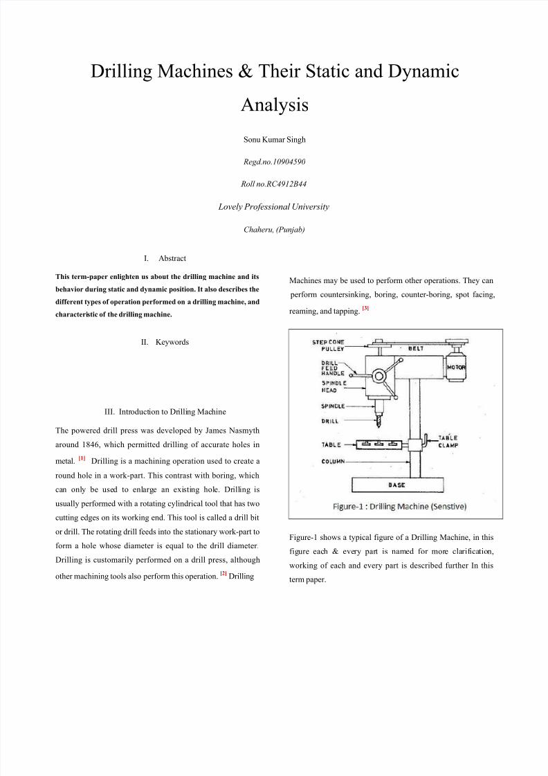
Drilling Machines & Their Static and Dynamic Analysis Sonu Kumar Singh Regd.no.10904590 Roll no.RC4912B44 Lovely Professional University Chaheru, (Punjab) I. Abstract This term-paper enlighten us about the drilling machine and its behavior during static and dynamic position. It also describes the different types of operation performed on a drilling machine, and characteri stic of the drilling machine. II. Keywords III. Intr oduct ion to Dr illi ng Mac hine The powered drill press was developed by James Nasmyth around 1846, which permitted drilling of accurate holes in metal. [1] Drilling is a machining operation used to create a round hole in a work-part. This contrast with boring, which can onl y be use d to enl arg e an exi sti ng hol e. Dr ill ing is usually performed with a rotating cylindrical tool that has two cutting edges on its working end. This tool is called a drill bit or drill. The rotating drill feeds into the stationary work-part to form a hole whose diameter is equal to the drill diameter. Drilling is customarily performed on a drill press, although other machining tools also perform this operation. [2] Drilling Machines may be used to perform other operations. They can perform countersinking, boring, counter-boring, spot facing, reaming, and tapping. [3] Figure-1 shows a typical figure of a Drilling Machine, in this fig ure eac h & eve ry par t is named for more cla rif ica tio n, working of each and every part is described further In this term paper.
-
Upload
sonukumarsinghbtechme -
Category
Documents
-
view
221 -
download
0
Transcript of Mec-202 Term Paper
8/8/2019 Mec-202 Term Paper
http://slidepdf.com/reader/full/mec-202-term-paper 1/15
Drilling Machines & Their Static and Dynamic
Analysis
Sonu Kumar Singh
Regd.no.10904590
Roll no.RC4912B44
Lovely Professional University
Chaheru, (Punjab)
I. Abstract
This term-paper enlighten us about the drilling machine and its
behavior during static and dynamic position. It also describes the
different types of operation performed on a drilling machine, and
characteristic of the drilling machine.
II. Keywords
III. Introduction to Drilling Machine
The powered drill press was developed by James Nasmyth
around 1846, which permitted drilling of accurate holes in
metal.[1]
Drilling is a machining operation used to create a
round hole in a work-part. This contrast with boring, which
can only be used to enlarge an existing hole. Drilling is
usually performed with a rotating cylindrical tool that has two
cutting edges on its working end. This tool is called a drill bit
or drill. The rotating drill feeds into the stationary work-part to
form a hole whose diameter is equal to the drill diameter.
Drilling is customarily performed on a drill press, although
other machining tools also perform this operation.[2]
Drilling
Machines may be used to perform other operations. They can
perform countersinking, boring, counter-boring, spot facing
reaming, and tapping.[3]
Figure-1 shows a typical figure of a Drilling Machine, in this
figure each & every part is named for more clarification
working of each and every part is described further In this
term paper.
8/8/2019 Mec-202 Term Paper
http://slidepdf.com/reader/full/mec-202-term-paper 2/15
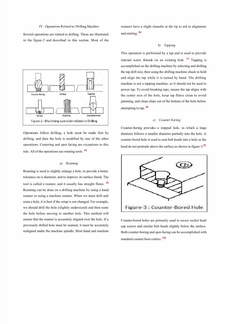
IV. Operations Related to Drilling Machine
Several operations are related to drilling. These are illustrated
in the figure-2 and described in this section. Most of the
Operations follow drilling; a hole must be made first by
drilling, and then the hole is modified by one of the other
operations. Centering and spot facing are exceptions to this
rule. All of the operations use rotating tools.[4]
a) Reaming
Reaming is used to slightly enlarge a hole, to provide a better
tolerance on is diameter, and to improve its surface finish. The
tool is called a reamer, and it usually has straight flutes.[5]
Reaming can be done on a drilling machine by using a hand
reamer or using a machine reamer. When we must drill and
ream a hole, it is best if the setup is not changed. For example,
we should drill the hole (slightly undersized) and then ream
the hole before moving to another hole. This method will
ensure that the reamer is accurately aligned over the hole. If a
previously drilled hole must be reamed, it must be accurately
realigned under the machine spindle. Most hand and machine
reamers have a slight chamfer at the tip to aid in alignment
and starting.[6]
b) Tapping
This operation is performed by a tap and is used to provide
internal screw threads on an existing hole.[7]
Tapping i
accomplished on the drilling machine by selecting and drilling
the tap drill size, then using the drilling machine chuck to hold
and align the tap while it is turned by hand. The drilling
machine is not a tapping machine, so it should not be used to
power tap. To avoid breaking taps, ensure the tap aligns with
the center axis of the hole, keep tap flutes clean to avoid
jamming, and clean chips out of the bottom of the hole before
attempting to tap.[8]
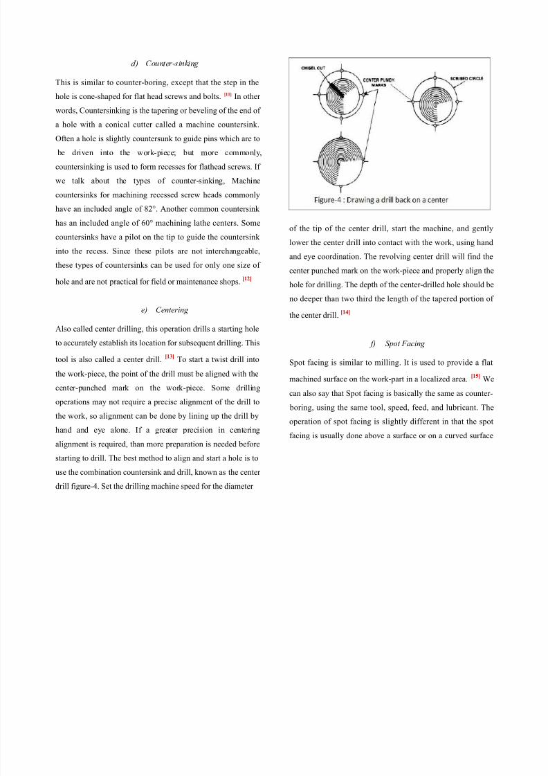
c) Counter-boring
Counter-boring provides a stepped hole, in which a large
diameter follows a smaller diameter partially into the hole. A
counter-bored hole is used to seat bolt heads into a hole so the
head do not protrude above the surface as shown in figure-3.[9]
Counter-bored holes are primarily used to recess socket head
cap screws and similar bolt heads slightly below the surface
Both counter-boring and spot-facing can be accomplished with
standard counter-bore cutters.[10]
8/8/2019 Mec-202 Term Paper
http://slidepdf.com/reader/full/mec-202-term-paper 3/15
d) Counter-sinking
This is similar to counter-boring, except that the step in the
hole is cone-shaped for flat head screws and bolts. [11] In other
words, Countersinking is the tapering or beveling of the end of
a hole with a conical cutter called a machine countersink.
Often a hole is slightly countersunk to guide pins which are to
be driven into the work-piece; but more commonly,
countersinking is used to form recesses for flathead screws. If
we talk about the types of counter-sinking, Machine
countersinks for machining recessed screw heads commonly
have an included angle of 82°. Another common countersink
has an included angle of 60° machining lathe centers. Some
countersinks have a pilot on the tip to guide the countersink
into the recess. Since these pilots are not interchangeable,
these types of countersinks can be used for only one size of
hole and are not practical for field or maintenance shops.[12]
e) Centering
Also called center drilling, this operation drills a starting hole
to accurately establish its location for subsequent drilling. This
tool is also called a center drill.[13]
To start a twist drill into
the work-piece, the point of the drill must be aligned with the
center-punched mark on the work-piece. Some drilling
operations may not require a precise alignment of the drill to
the work, so alignment can be done by lining up the drill by
hand and eye alone. If a greater precision in centering
alignment is required, than more preparation is needed before
starting to drill. The best method to align and start a hole is to
use the combination countersink and drill, known as the center
drill figure-4. Set the drilling machine speed for the diameter
of the tip of the center drill, start the machine, and gently
lower the center drill into contact with the work, using hand
and eye coordination. The revolving center drill will find the
center punched mark on the work-piece and properly align the
hole for drilling. The depth of the center-drilled hole should be
no deeper than two third the length of the tapered portion of
the center drill.[14]
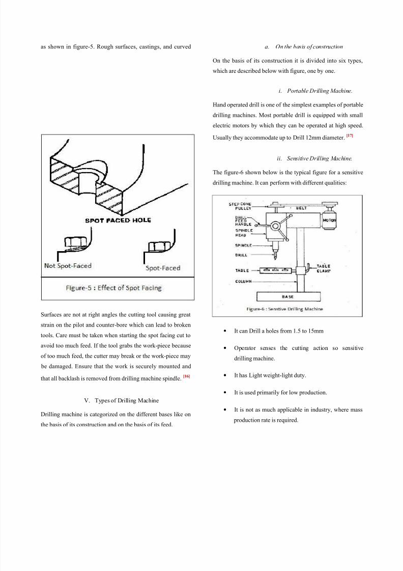
f) Spot Facing
Spot facing is similar to milling. It is used to provide a flat
machined surface on the work-part in a localized area.[15]
We
can also say that Spot facing is basically the same as counter-
boring, using the same tool, speed, feed, and lubricant. The
operation of spot facing is slightly different in that the spot
facing is usually done above a surface or on a curved surface
8/8/2019 Mec-202 Term Paper
http://slidepdf.com/reader/full/mec-202-term-paper 4/15
as shown in figure-5. Rough surfaces, castings, and curved
Surfaces are not at right angles the cutting tool causing great
strain on the pilot and counter-bore which can lead to broken
tools. Care must be taken when starting the spot facing cut to
avoid too much feed. If the tool grabs the work-piece because
of too much feed, the cutter may break or the work-piece may
be damaged. Ensure that the work is securely mounted and
that all backlash is removed from drilling machine spindle.[16]
V. Types of Drilling Machine
Drilling machine is categorized on the different bases like on
the basis of its construction and on the basis of its feed.
a. On the basis of construction
On the basis of its construction it is divided into six types
which are described below with figure, one by one.
i. Portable Drilling Machine.
Hand operated drill is one of the simplest examples of portable
drilling machines. Most portable drill is equipped with small
electric motors by which they can be operated at high speed
Usually they accommodate up to Drill 12mm diameter.[17]
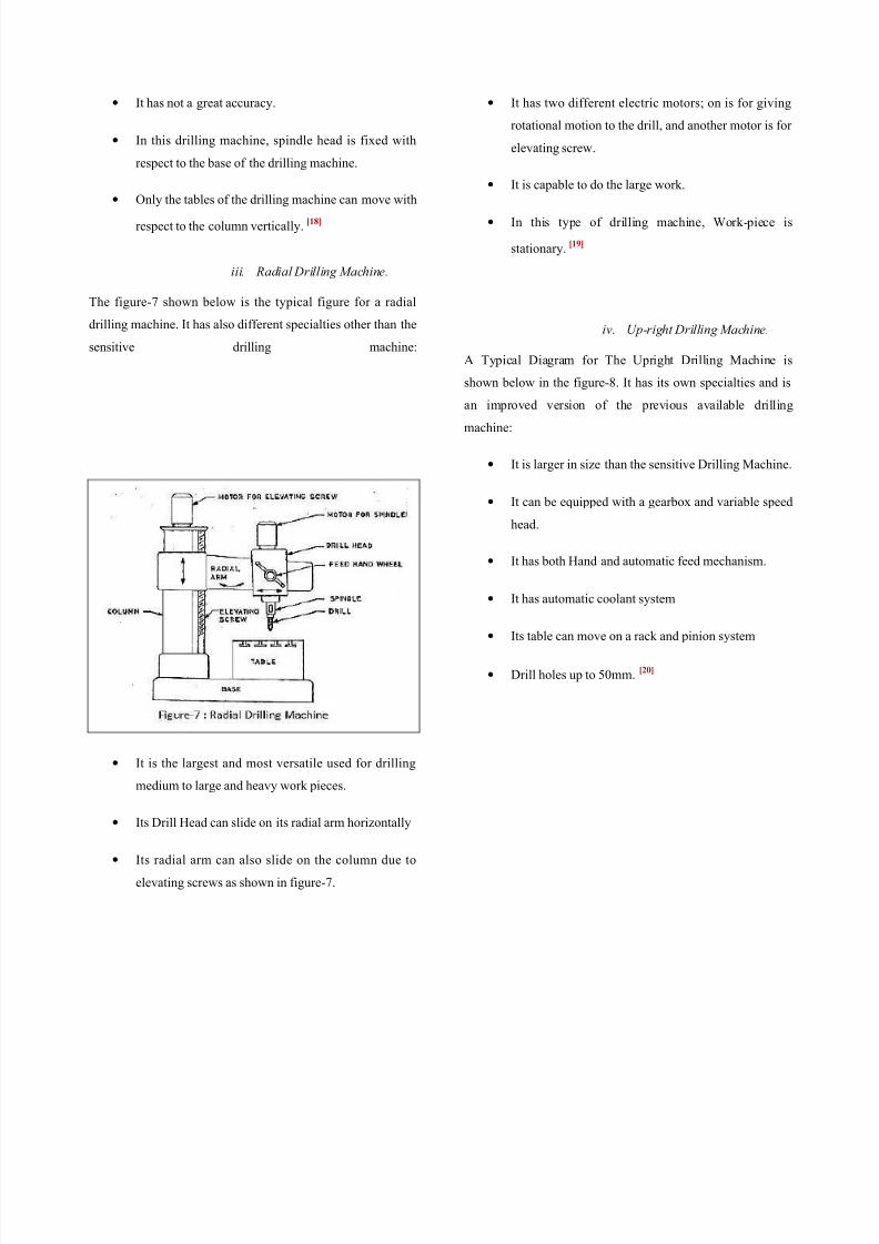
ii. Sensitive Drilling Machine.
The figure-6 shown below is the typical figure for a sensitive
drilling machine. It can perform with different qualities:
• It can Drill a holes from 1.5 to 15mm
• Operator senses the cutting action so sensitive
drilling machine.
• It has Light weight-light duty.
• It is used primarily for low production.
• It is not as much applicable in industry, where mass
production rate is required.
8/8/2019 Mec-202 Term Paper
http://slidepdf.com/reader/full/mec-202-term-paper 5/15
• It has not a great accuracy.
• In this drilling machine, spindle head is fixed with
respect to the base of the drilling machine.
• Only the tables of the drilling machine can move with
respect to the column vertically.[18]
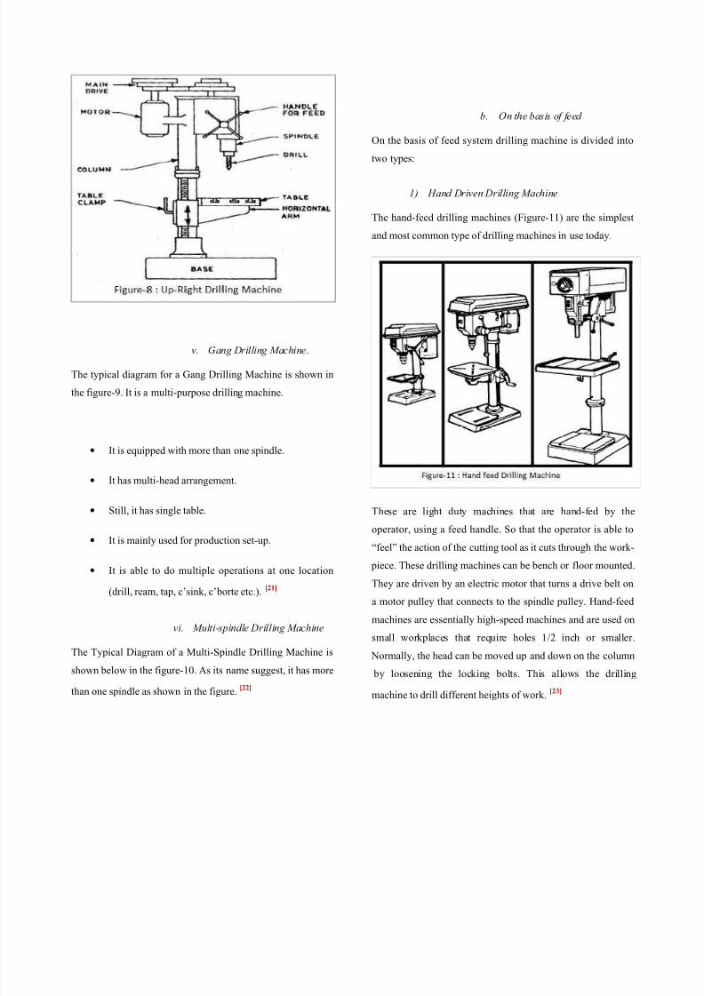
iii. Radial Drilling Machine.
The figure-7 shown below is the typical figure for a radial
drilling machine. It has also different specialties other than the
sensitive drilling machine:
• It is the largest and most versatile used for drilling
medium to large and heavy work pieces.
• Its Drill Head can slide on its radial arm horizontally
• Its radial arm can also slide on the column due to
elevating screws as shown in figure-7.
• It has two different electric motors; on is for giving
rotational motion to the drill, and another motor is for
elevating screw.
• It is capable to do the large work.
• In this type of drilling machine, Work-piece i
stationary.[19]
iv. Up-right Drilling Machine.
A Typical Diagram for The Upright Drilling Machine i
shown below in the figure-8. It has its own specialties and is
an improved version of the previous available drilling
machine:
• It is larger in size than the sensitive Drilling Machine
• It can be equipped with a gearbox and variable speed
head.
• It has both Hand and automatic feed mechanism.
• It has automatic coolant system
• Its table can move on a rack and pinion system
• Drill holes up to 50mm.[20]
8/8/2019 Mec-202 Term Paper
http://slidepdf.com/reader/full/mec-202-term-paper 6/15
v. Gang Drilling Machine.
The typical diagram for a Gang Drilling Machine is shown in
the figure-9. It is a multi-purpose drilling machine.
• It is equipped with more than one spindle.
• It has multi-head arrangement.
• Still, it has single table.
• It is mainly used for production set-up.
• It is able to do multiple operations at one location
(drill, ream, tap, c’sink, c’borte etc.).[21]
vi. Multi-spindle Drilling Machine
The Typical Diagram of a Multi-Spindle Drilling Machine is
shown below in the figure-10. As its name suggest, it has more
than one spindle as shown in the figure.[22]
b. On the basis of feed
On the basis of feed system drilling machine is divided into
two types:
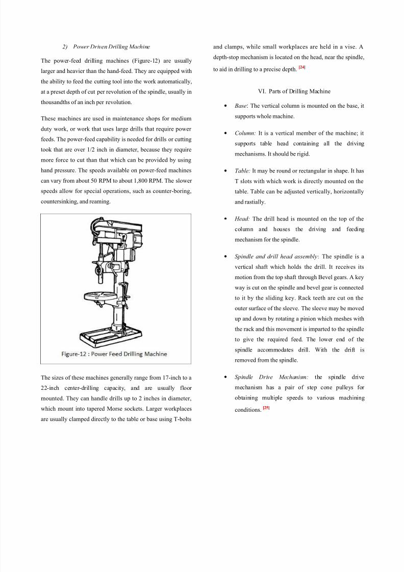
1) Hand Driven Drilling Machine
The hand-feed drilling machines (Figure-11) are the simplest
and most common type of drilling machines in use today.
These are light duty machines that are hand-fed by the
operator, using a feed handle. So that the operator is able to
“feel” the action of the cutting tool as it cuts through the work
piece. These drilling machines can be bench or floor mounted
They are driven by an electric motor that turns a drive belt on
a motor pulley that connects to the spindle pulley. Hand-feed
machines are essentially high-speed machines and are used on
small workplaces that require holes 1/2 inch or smaller
Normally, the head can be moved up and down on the column
by loosening the locking bolts. This allows the drillin
machine to drill different heights of work.[23]
8/8/2019 Mec-202 Term Paper
http://slidepdf.com/reader/full/mec-202-term-paper 7/15
8/8/2019 Mec-202 Term Paper
http://slidepdf.com/reader/full/mec-202-term-paper 8/15
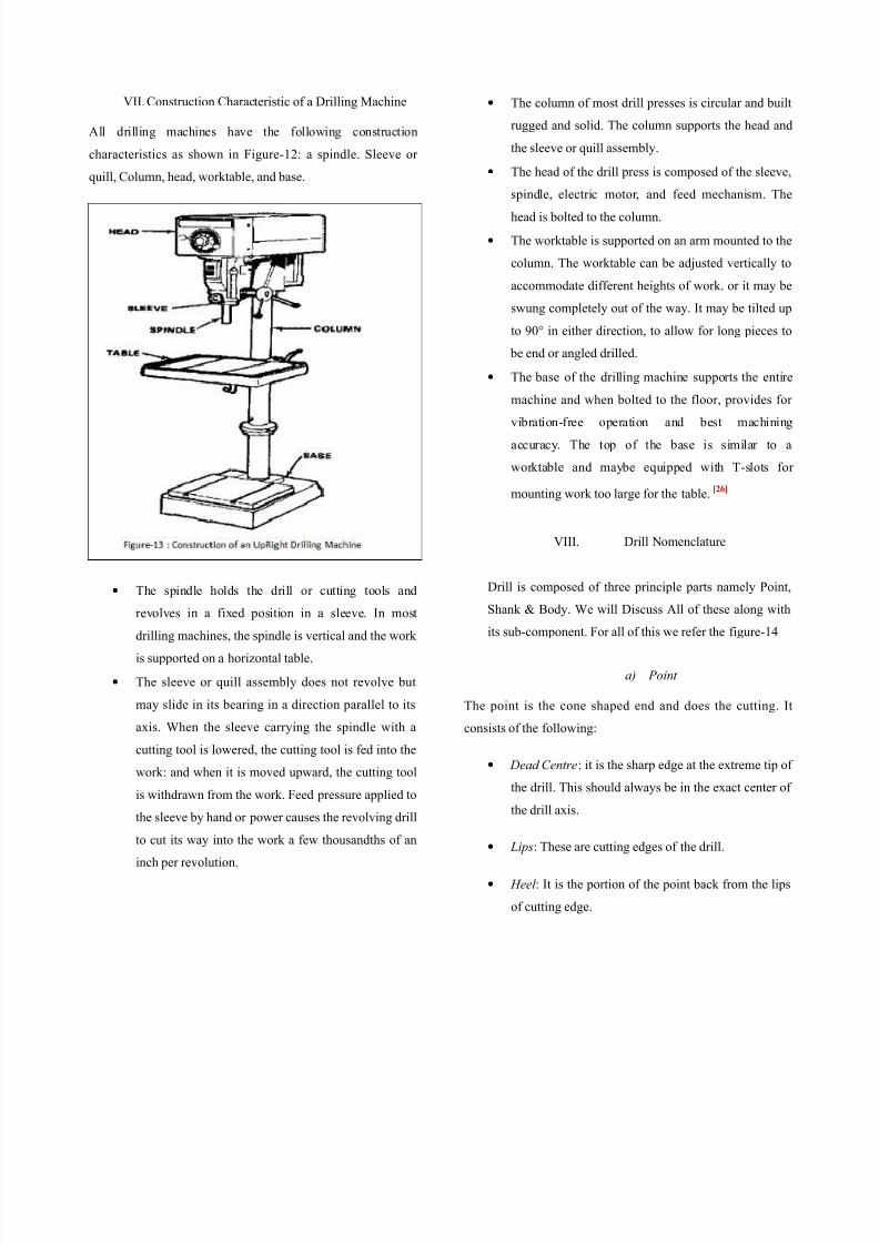
VII. Construction Characteristic of a Drilling Machine
All drilling machines have the following construction
characteristics as shown in Figure-12: a spindle. Sleeve or
quill, Column, head, worktable, and base.
•
The spindle holds the drill or cutting tools andrevolves in a fixed position in a sleeve. In most
drilling machines, the spindle is vertical and the work
is supported on a horizontal table.
• The sleeve or quill assembly does not revolve but
may slide in its bearing in a direction parallel to its
axis. When the sleeve carrying the spindle with a
cutting tool is lowered, the cutting tool is fed into the
work: and when it is moved upward, the cutting tool
is withdrawn from the work. Feed pressure applied to
the sleeve by hand or power causes the revolving drill
to cut its way into the work a few thousandths of an
inch per revolution.
• The column of most drill presses is circular and built
rugged and solid. The column supports the head and
the sleeve or quill assembly.
• The head of the drill press is composed of the sleeve
spindle, electric motor, and feed mechanism. Thehead is bolted to the column.
• The worktable is supported on an arm mounted to the
column. The worktable can be adjusted vertically to
accommodate different heights of work. or it may be
swung completely out of the way. It may be tilted up
to 90° in either direction, to allow for long pieces to
be end or angled drilled.
• The base of the drilling machine supports the entire
machine and when bolted to the floor, provides for
vibration-free operation and best machining
accuracy. The top of the base is similar to a
worktable and maybe equipped with T-slots fo
mounting work too large for the table.[26]
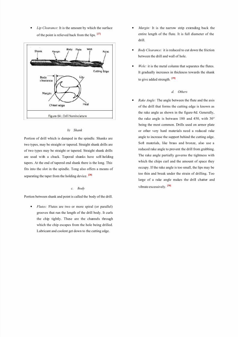
VIII. Drill Nomenclature
Drill is composed of three principle parts namely Point
Shank & Body. We will Discuss All of these along with
its sub-component. For all of this we refer the figure-14
a) Point
The point is the cone shaped end and does the cutting. I
consists of the following:
• Dead Centre: it is the sharp edge at the extreme tip o
the drill. This should always be in the exact center of
the drill axis.
• Lips: These are cutting edges of the drill.
• Heel : It is the portion of the point back from the lips
of cutting edge.
8/8/2019 Mec-202 Term Paper
http://slidepdf.com/reader/full/mec-202-term-paper 9/15
• Lip Clearance: It is the amount by which the surface
of the point is relieved back from the lips.[27]
b) Shank
Portion of drill which is damped in the spindle. Shanks are
two types, may be straight or tapered. Straight shank drills are
of two types may be straight or tapered. Straight shank drills
are used with a chuck. Tapered shanks have self-holding
tapers. At the end of tapered end shank there is the long. This
fits into the slot in the spindle. Tong also offers a means of
separating the taper from the holding device.[28]
c. Body
Portion between shank and point is called the body of the drill.
• Flutes: Flutes are two or more spiral (or parallel)
grooves that run the length of the drill body. It curls
the chip tightly. These are the channels through
which the chip escapes from the hole being drilled.
Lubricant and coolent get down to the cutting edge.
• Margin: It is the narrow strip extending back the
entire length of the flute. It is full diameter of the
drill.
• Body Clearance: it is reduced to cut down the friction
between the drill and wall of hole.
• Wele: it is the metal column that separates the flutes
It gradually increases in thickness towards the shank
to give added strength.[29]
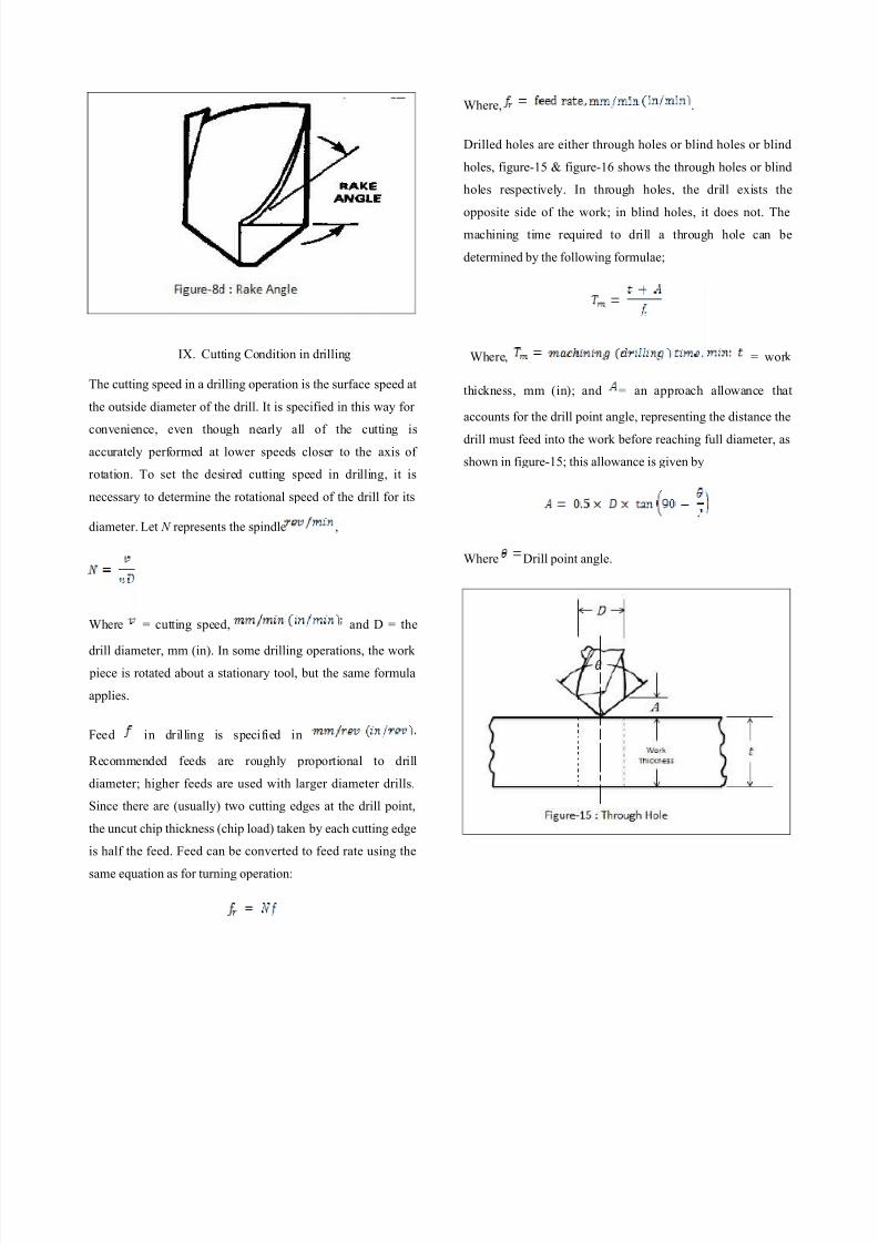
d. Others
• Rake Angle: The angle between the flute and the axis
of the drill that forms the cutting edge is known asthe rake angle as shown in the figure-8d. Generally
the rake angle is between 180 and 450, with 30°
being the most common. Drills used on armor plate
or other very hard materials need a reduced rake
angle to increase the support behind the cutting edge
Soft materials, like brass and bronze, also use a
reduced rake angle to prevent the drill from grabbing
The rake angle partially governs the tightness with
which the chips curl and the amount of space they
occupy. If the rake angle is too small, the lips may be
too thin and break under the strain of drilling. Too
large of a rake angle makes the drill chatter and
vibrate excessively.[30]
8/8/2019 Mec-202 Term Paper
http://slidepdf.com/reader/full/mec-202-term-paper 10/15
IX. Cutting Condition in drilling
The cutting speed in a drilling operation is the surface speed at
the outside diameter of the drill. It is specified in this way for
convenience, even though nearly all of the cutting is
accurately performed at lower speeds closer to the axis of
rotation. To set the desired cutting speed in drilling, it is
necessary to determine the rotational speed of the drill for its
diameter. Let N represents the spindle ,
Where = cutting speed, and D = the
drill diameter, mm (in). In some drilling operations, the work
piece is rotated about a stationary tool, but the same formula
applies.
Feed in drilling is specified in
Recommended feeds are roughly proportional to drill
diameter; higher feeds are used with larger diameter drills.
Since there are (usually) two cutting edges at the drill point,
the uncut chip thickness (chip load) taken by each cutting edge
is half the feed. Feed can be converted to feed rate using the
same equation as for turning operation:
Where, .
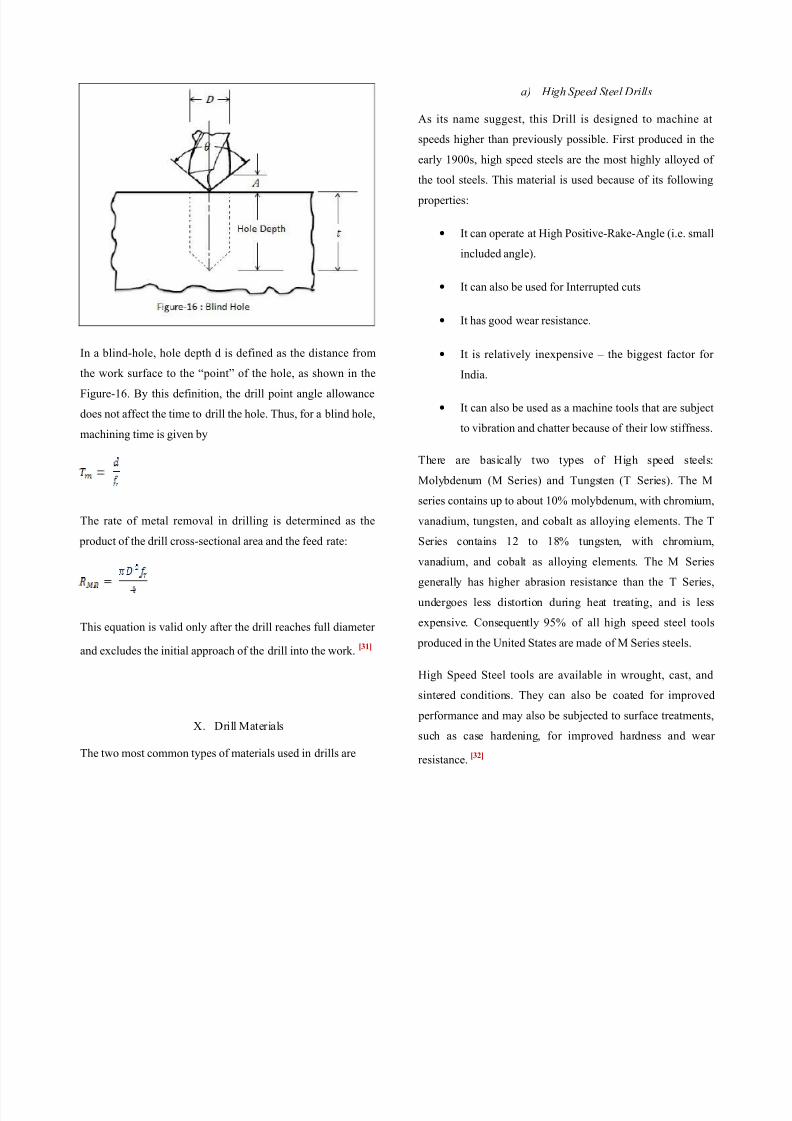
Drilled holes are either through holes or blind holes or blind
holes, figure-15 & figure-16 shows the through holes or blind
holes respectively. In through holes, the drill exists the
opposite side of the work; in blind holes, it does not. The
machining time required to drill a through hole can be
determined by the following formulae;
Where, = work
thickness, mm (in); and = an approach allowance tha
accounts for the drill point angle, representing the distance the
drill must feed into the work before reaching full diameter, as
shown in figure-15; this allowance is given by
Where Drill point angle.
8/8/2019 Mec-202 Term Paper
http://slidepdf.com/reader/full/mec-202-term-paper 11/15
8/8/2019 Mec-202 Term Paper
http://slidepdf.com/reader/full/mec-202-term-paper 12/15
b) Carbide-Tipped drills
Most of the tool materials have the limitations, such as they
cannot be used as effectively where high cutting speeds, and
hence high temperatures, are invoked, and their tool life can
be relatively short. Carbides, also known as cemented or
sintered carbides, were introduced in the 1930s to meet the
challenge of higher machining speeds for higher production
rates.
Because of their high hardness over a wide range of
temperatures, high elastic modulus and thermal conductivity,
and low thermal expansion, carbides are among the most
important, versatile, and cost effective tool and die materials
for a wide range of applications. However, stiffness of themachine tool is important and light feeds, low cutting speeds,
and chatter can be determined, that’s why this material is used
as drill.
The two basic groups of carbides used for Drilling operations
are tungsten carbide and titanium carbide. In order to
differentiate them from coated tools or tipped tools, plain
carbide tools are usually referred to as uncoated carbides.[33]
c) Other materials for Drill
There are still some other options as a drill material which is
listed below.
• Solid Carbide drill.
• TiN coated drills.
• Carbide coated masonry drills.
• Parabolic drills.
• Split point drills.[34]
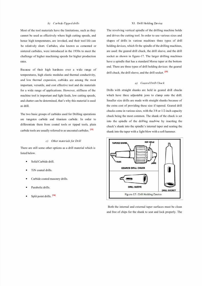
XI. Drill Holding Device
The revolving vertical spindle of the drilling machine holds
and drives the cutting tool. In order to use various sizes and
shapes of drills in various machines three types of dril
holding devices, which fit the spindle of the drilling machines
are used: the geared drill chuck, the drill sleeve, and the dril
socket as shown in figure-17. The larger drilling machines
have a spindle that has a standard Morse taper at the bottom
end. There are three types of drill holding devices: the geared
drill chuck, the drill sleeve, and the drill socket.[35]
a) Geared Drill Chuck
Drills with straight shanks are held in geared drill chuckswhich have three adjustable jaws to clamp onto the drill
Smaller size drills are made with straight shanks because of
the extra cost of providing these size if tapered. Geared dril
chucks come in various sizes, with the 3/8 or 1/2-inch capacity
chuck being the most common. The shank of the chuck is set
into the spindle of the drilling machine by inserting the
chuck’s shank into the spindle’s internal taper and seating the
shank into the taper with a light blow with a soft hammer.
Both the internal and external taper surfaces must be clean
and free of chips for the shank to seat and lock properly. The
8/8/2019 Mec-202 Term Paper
http://slidepdf.com/reader/full/mec-202-term-paper 13/15
drill is locked into the chuck by using the chuck key to
simultaneously tighten the three chuck jaws. Geared drill
chucks can also come with a Morse tapered shank and may
have a different method of attaching they may screw on, have
a Jarno taper, or a Jacob’s back taper.[36]
b) Drill sleeve & Drill Socket
Morse taper shank drills come in several sizes, thus, adapters
must be used for mounting them into various drilling machine
spindles. Drill sleeves and drill sockets are designed to add to
or subtract from the Morse taper for fitting a drill into the
chuck spindle. For example, it is common for a 3/4 inch twist
drill to have a Morse taper of size #2, #3, or #4. It is also
common for a drilling machine spindle to have a Morse taper
of size #3 or #4, and it can be adapted for many other Morse
taper sizes, depending on the size of the drill.
A drill too small for the machine spindle may be fitted into a
socket or sleeve which has a taper hole of the proper size to
hold the drill and a taper shank of the proper size to fit the drill
spindle. Sometimes, more than one socket or sleeve is needed
to build up the shank to tit into the drilling machine spindle.
Sockets and sleeves may be obtained in a number of different
sizes and hole shank taper combinations. Sockets, sleeves, and
taper shank drills are mounted into the aligning slots of the
spindle and lightly tapped with a soft hammer to seat in place.
[37]
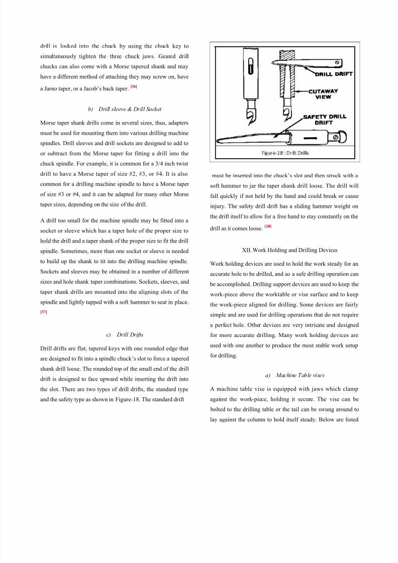
c) Drill Drifts
Drill drifts are flat, tapered keys with one rounded edge that
are designed to fit into a spindle chuck’s slot to force a taperedshank drill loose. The rounded top of the small end of the drill
drift is designed to face upward while inserting the drift into
the slot. There are two types of drill drifts, the standard type
and the safety type as shown in Figure-18. The standard drift
must be inserted into the chuck’s slot and then struck with a
soft hammer to jar the taper shank drill loose. The drill wil
fall quickly if not held by the hand and could break or cause
injury. The safety drill drift has a sliding hammer weight on
the drift itself to allow for a free hand to stay constantly on the
drill as it comes loose.[38]
XII. Work Holding and Drilling Devices
Work holding devices are used to hold the work steady for an
accurate hole to be drilled, and so a safe drilling operation can
be accomplished. Drilling support devices are used to keep the
work-piece above the worktable or vise surface and to keep
the work-piece aligned for drilling. Some devices are fairly
simple and are used for drilling operations that do not require
a perfect hole. Other devices are very intricate and designed
for more accurate drilling. Many work holding devices are
used with one another to produce the most stable work setup
for drilling.
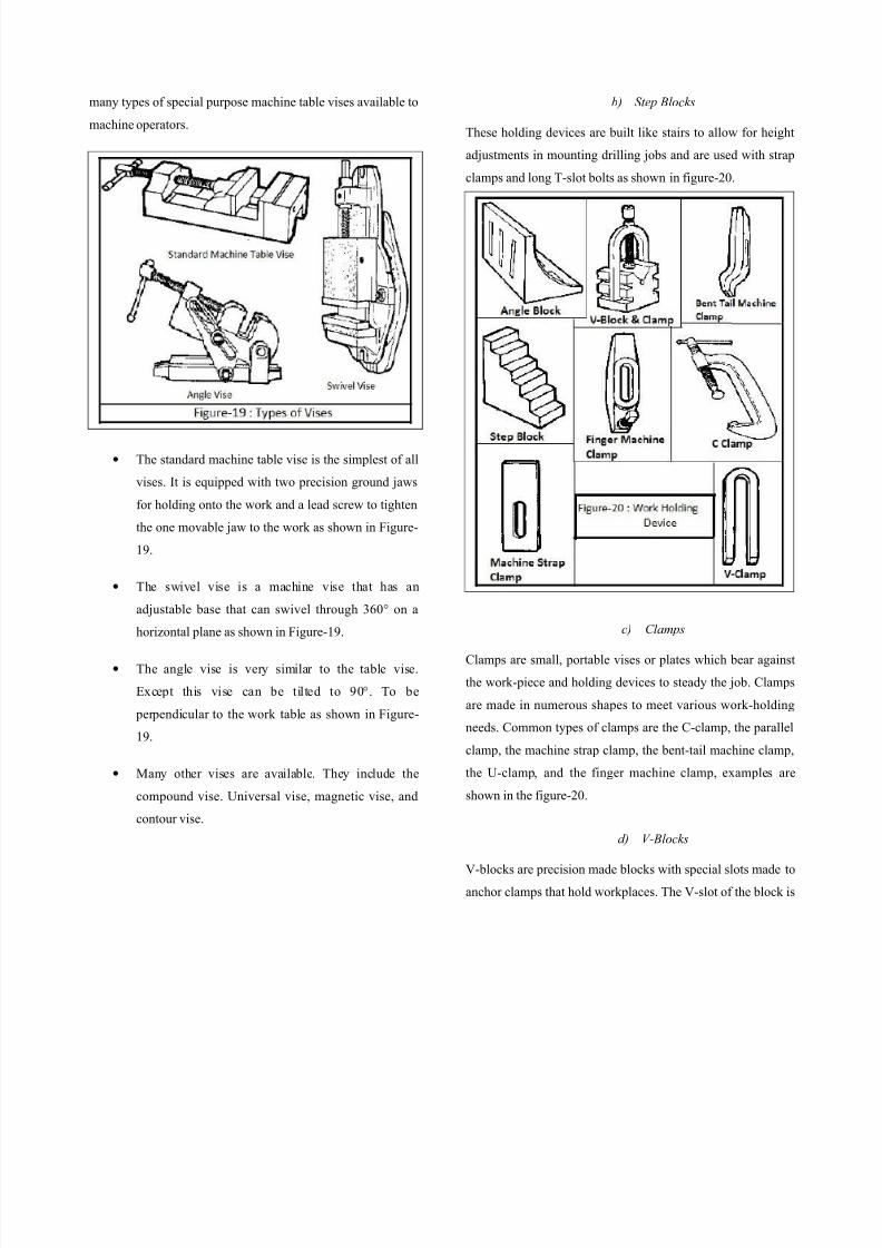
a) Machine Table vises
A machine table vise is equipped with jaws which clamp
against the work-piece, holding it secure. The vise can be
bolted to the drilling table or the tail can be swung around to
lay against the column to hold itself steady. Below are listed
8/8/2019 Mec-202 Term Paper
http://slidepdf.com/reader/full/mec-202-term-paper 14/15
many types of special purpose machine table vises available to
machine operators.
• The standard machine table vise is the simplest of all
vises. It is equipped with two precision ground jaws
for holding onto the work and a lead screw to tighten
the one movable jaw to the work as shown in Figure-
19.
• The swivel vise is a machine vise that has an
adjustable base that can swivel through 360° on a
horizontal plane as shown in Figure-19.
• The angle vise is very similar to the table vise.
Except this vise can be tilted to 90°. To be
perpendicular to the work table as shown in Figure-
19.
• Many other vises are available. They include the
compound vise. Universal vise, magnetic vise, and
contour vise.
b) Step Blocks
These holding devices are built like stairs to allow for height
adjustments in mounting drilling jobs and are used with strap
clamps and long T-slot bolts as shown in figure-20.
c) Clamps
Clamps are small, portable vises or plates which bear agains
the work-piece and holding devices to steady the job. Clamps
are made in numerous shapes to meet various work-holding
needs. Common types of clamps are the C-clamp, the parallel
clamp, the machine strap clamp, the bent-tail machine clamp
the U-clamp, and the finger machine clamp, examples are
shown in the figure-20.
d) V-Blocks
V-blocks are precision made blocks with special slots made to
anchor clamps that hold workplaces. The V-slot of the block is
8/8/2019 Mec-202 Term Paper
http://slidepdf.com/reader/full/mec-202-term-paper 15/15
designed to hold round workplaces. The V-block and clamp
set is usually used to hold and drill round stock
e. Angle Plates
Angle plates are made in a 900 angle with slots and bolt holes
for securing work to the table or to other work holding
devices, examples are shown in the figure-20.
f. T-Slot Bolts
These specially made bolts have a T-shaped head that is
designed to slide into the T-slots of the drilling machine’s
worktable. A heavy duty washer and nut are used with the T-
bolt to secure the work.
g. Jigs
Drill jigs are devices designed for production drilling jobs.
The workplaces are clamped into the jig so that the holes will
be drilled in the same location on each piece. The jig may
guide the drill through a steel bushing to locate the holes
accurately.[39]
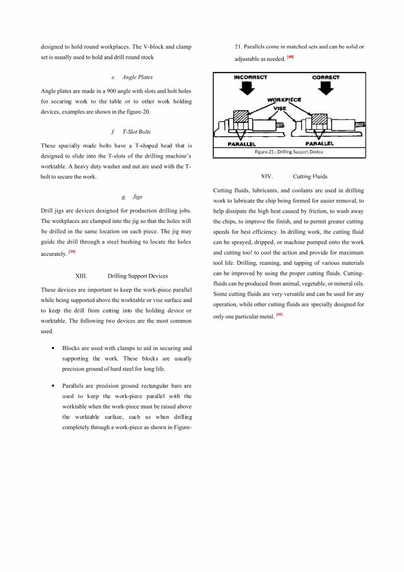
XIII. Drilling Support Devices
These devices are important to keep the work-piece parallel
while being supported above the worktable or vise surface and
to keep the drill from cutting into the holding device or
worktable. The following two devices are the most common
used.
• Blocks are used with clamps to aid in securing and
supporting the work. These blocks are usually
precision ground of hard steel for long life.
• Parallels are precision ground rectangular bars are
used to keep the work-piece parallel with the
worktable when the work-piece must be raised above
the worktable surface, such as when drilling
completely through a work-piece as shown in Figure-
21. Parallels come in matched sets and can be solid or
adjustable as needed.[40]
XIV. Cutting Fluids
Cutting fluids, lubricants, and coolants are used in drilling
work to lubricate the chip being formed for easier removal, to
help dissipate the high heat caused by friction, to wash away
the chips, to improve the finish, and to permit greater cutting
speeds for best efficiency. In drilling work, the cutting fluid
can be sprayed, dripped, or machine pumped onto the work
and cutting too! to cool the action and provide for maximum
tool life. Drilling, reaming, and tapping of various materials
can be improved by using the proper cutting fluids. Cutting-fluids can be produced from animal, vegetable, or mineral oils
Some cutting fluids are very versatile and can be used for any
operation, while other cutting fluids are specially designed for
only one particular metal.[41]