Kotłowe technologie nadkrytyczne
54
Technologie nadkrytyczne w energetyce – jeden ze sposobów wzrostu sprawności wytwarzania energii sposobów wzrostu sprawności wytwarzania energii elektrycznej i ograniczania emisji CO2 Jaroslaw Mlonka 10-24.05.2011
Transcript of Kotłowe technologie nadkrytyczne
Technologie nadkrytyczne w energetyce – jeden ze sposobów wzrostu sprawności wytwarzania energii sposobów wzrostu sprawności wytwarzania energii
elektrycznej i ograniczania emisji CO2
Jarosław Mlonka10-24.05.2011

Efficiency in Efficiency in ElectricityElectricity GenerationGeneration
20
30
40
50
60
70
80
90
100
Eff
icie
ncy (
%)
0
10
20
Hyd
ro p
ower
pla
nt
Tida
l pow
er p
lant
Larg
e ga
s fir
ed C
CG
T po
wer
pla
nt
Mel
ted
carb
onat
es fu
el c
ell (
MC
FC)
Pul
veris
ed c
oal b
oile
rs w
ith u
ltra-
criti
cal s
team
par
amet
ers
Sol
id o
xide
fuel
cel
l (S
OFC
)
Coa
l fire
d IG
CC
Atm
osph
eric
Circ
ulat
ing
Flui
dise
d B
ed C
ombu
stio
n (C
FBC
)
Pre
ssur
ised
Flu
idis
ed B
ed C
ombu
stio
n (P
FBC
)
Larg
e ga
s tu
rbin
e (M
W ra
nge)
Ste
am tu
rbin
e co
al-fi
red
pow
er p
lant
Ste
am tu
rbin
e fu
el-o
il po
wer
pla
ntW
ind
turb
ine
Nuc
lear
pow
er p
lant
Bio
mas
s an
d bi
ogas
Was
te-to
-ele
ctric
ity p
ower
pla
nt
Die
sel e
ngin
e as
dec
entra
lised
CH
P u
nit (
elec
trica
l sha
re)
Sm
all a
nd m
icro
turb
ines
(up
to 1
00 k
W)
Pho
tovo
ltaic
cel
ls
Geo
ther
mal
pow
er p
lant
Sol
ar p
ower
tow
er
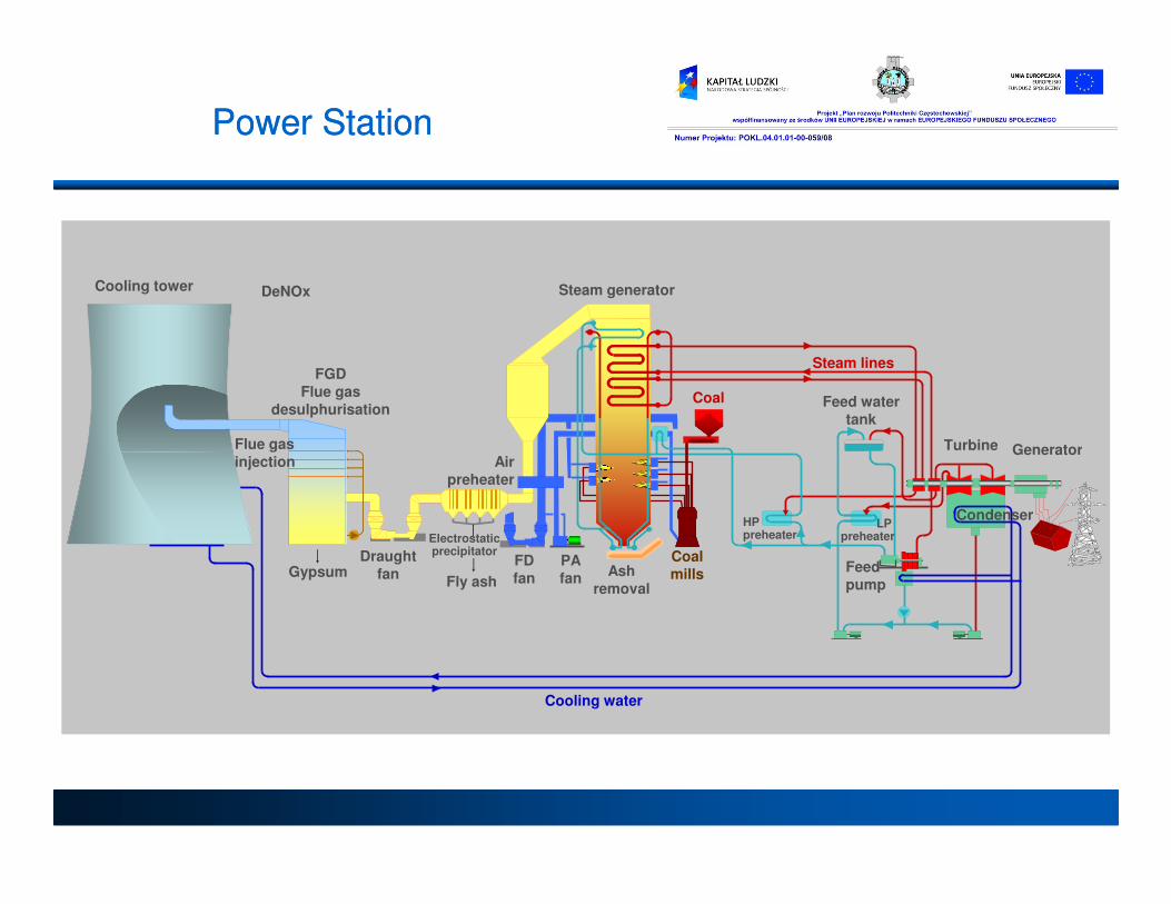
Cooling tower
Steam lines
Steam generator
Coal
Flue gas
FGDFlue gas
desulphurisation
Turbine Generator
Feed watertank
DeNOx
Power StationPower Station
injection
Draughtfan
Cooling water
PAfan
CoalmillsAsh
removal
Turbine Generator
Feedpump
Electrostaticprecipitator
LP preheater
HP preheater
Condenser
GypsumFly ash
Airpreheater
FDfan
"Supercritical" is a thermodynamic expression describing the state of a substance where there is no clear distinction between the liquid and the gaseous phase (i.e. they are a homogenous fluid). Water reaches this state at a pressure above 22.1 megapascals (MPa) Up to an operating pressure of around 19 MPa in the evaporator part of the boiler, the cycle is sub-critical. This means, that there is a non-homogeneous mixture of water and steam in the evaporator part of the boiler. In this case a drum-type boiler is used because the steam needs to be separated from water in the drum of the boiler before it is superheated and led into the turbine. Above an operating
Subcritical and a Supercritical boiler
boiler before it is superheated and led into the turbine. Above an operating pressure of 22.1 MPa in the evaporator part of the boiler, the cycle is supercritical. The cycle medium is a single phase fluid with homogeneous properties and there is no need to separate steam from water in a drum. Once-through boilers are therefore used in supercritical cycles.

OTU OTU vsvs DRUM BOILERDRUM BOILERMain Difference is in Furnace Evaporator DesignMain Difference is in Furnace Evaporator Design
Natural Circulation Drum TypeSpiral Once Through Unit Design
• Common Furnace Sizing Criteria
• Identical Convection Pass Design Arrangement
• Common Firing Systems
• Common Auxiliary Systems

OTU OTU vsvs DRUM BOILERDRUM BOILERMain Difference is in Furnace Main Difference is in Furnace Evaporator Evaporator DesignDesign

Supercritical power plants were in service from the late sixties. But the technology did not really take off due to problems of reliability especially from the metallurgical aspect.The single most important factor that determines the use of higher and higher pressure and temperatures are the availability of materials to withstand these conditions. Increases in operating pressure and temperatures have to go hand in hand with developments in metallurgy.
•With more than 600 units in service the reliability issue seems to be resolved. Supercritical units are the standard for future power plants in many countries including China. (valid for 560-600/580-605 C)•The main advantage and the reason for a higher pressure operation is the increase in the thermodynamic efficiency of the Rankine cycle
SupercriticalSupercritical versusversus subcriticalsubcritical
increase in the thermodynamic efficiency of the Rankine cycle•Supercritical units use the once through technology. This is ideal for sliding pressure operation which has much more flexibility in load changes and controlling the power grid.•Water chemistry In supercritical units the water entering the boiler has to be of extremely high levels of purity. Supercritical boilers do not have a steam drum that separates the steam and the water. If the entering water quality is not good, carry over of impurities can result in turbine blade deposits
-

FLUID TEMPERATURE CHANGEFLUID TEMPERATURE CHANGEOTU OTU vsvs Drum BoilersDrum Boilers
TE
MP
ER
AT
UR
E (
F)
ECON EVAP SPHTR
CONTINUOUS INCREASE IN TEMPERATURE
OTU 4000
psi
a NATURAL CIRCULATION
ENTHALPY (Btu/lb)
TE
MP
ER
AT
UR
E (
F)
50% 100% QUALITY0%
ECON EVAP SPHTR
CONSTANT SAT. TEMP.
RECIRC. LIMITS QUALITY
DRUM
ONCE-THROUGH
The Evolution ContinuesThe Evolution Continues
3
Comparison
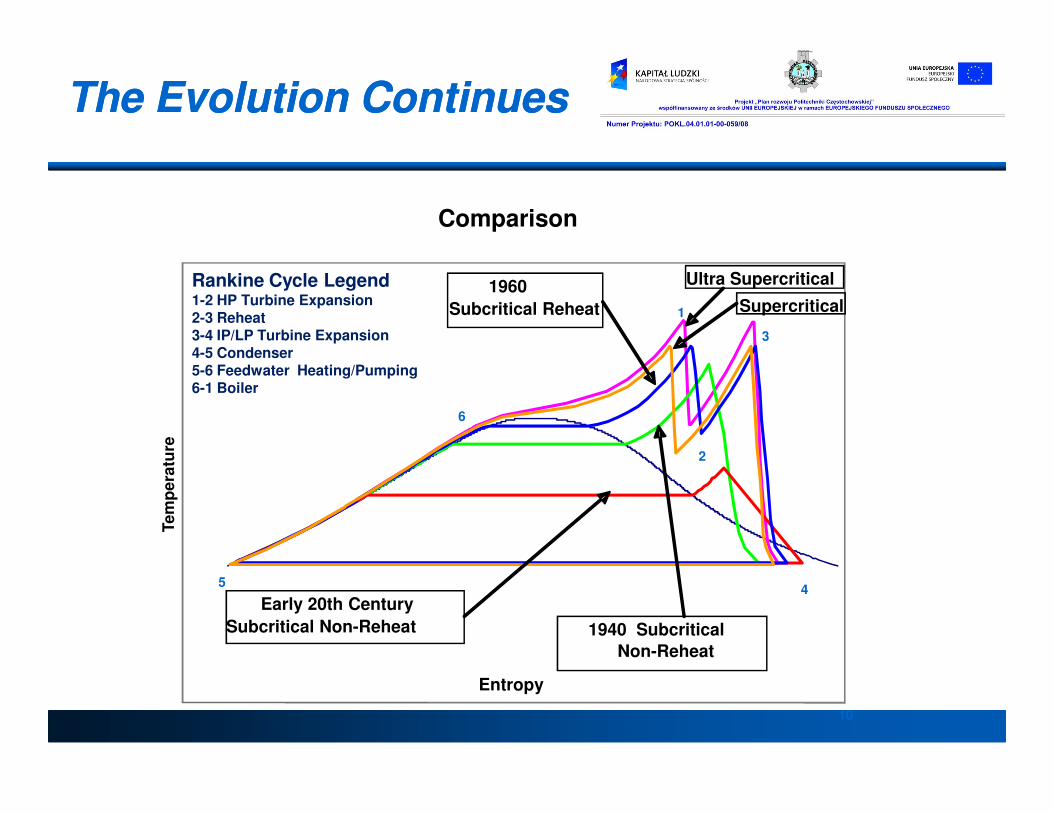
Ultra Supercritical1960
Subcritical Reheat Supercritical
Rankine Cycle Legend1-2 HP Turbine Expansion2-3 Reheat3-4 IP/LP Turbine Expansion4-5 Condenser5-6 Feedwater Heating/Pumping6-1 Boiler
1
10
Entropy
Te
mp
era
ture
1940 Subcritical
Non-Reheat
Early 20th Century
Subcritical Non-Reheat
2
45
6
Technologia kotłów przepływowychTechnologia kotłów przepływowych
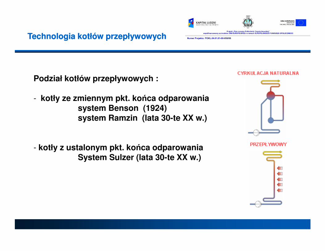
Podział kotłów przepływowych :
- kotły ze zmiennym pkt. końca odparowaniasystem Benson (1924)system Ramzin (lata 30-te XX w.)
- kotły z ustalonym pkt. końca odparowaniaSystem Sulzer (lata 30-te XX w.)

Parametry Jedn. Schwarze Pumpe
(Niemcy)
Lippendorf 1,2
(Niemcy)
Niederaussem K(BoA)
(Niemcy)
Pątnów Blok A
(Polska)
Esbjerg
(Dania)
Nordjylland (Dania)
Łagisza
(Polska)
Węgiel - brunatny brunatny brunatny brunatny kamienny kamienny kamienny
Moc brutto MW 800 936 1012 460 415 411 460(kocioł
fluid.)
Temperatura pary świeżej przed
turbiną
oC
544
550
575
540
560
580
560
Ciśnienie pary świeżej prze turbiną
MPa
26,0
26,0
26,4
25,8
25,0
29,0
27,5
Europejskie referencje kotłów Europejskie referencje kotłów przepływowychprzepływowych
świeżej prze turbiną MPa 26,0 26,0 26,4 25,8 25,0 29,0 27,5
Temperatura pary wtórnie przegrzanej
oC
562
582
599
565
560
580/580
580
Temperatura wody zasilającej
oC
274
270
295
275
275
300
290
Ciśnienie w skraplaczu
kPa 35/46 38,0 36 45/50 23 23 45/50
Sprawność energetyczna netto
%
41,0
42,3
45,2
41,0
45,0
47,0
43,0
Rok kontraktacji - 1997/98 99/00 2002 2004 1992 1998 2005
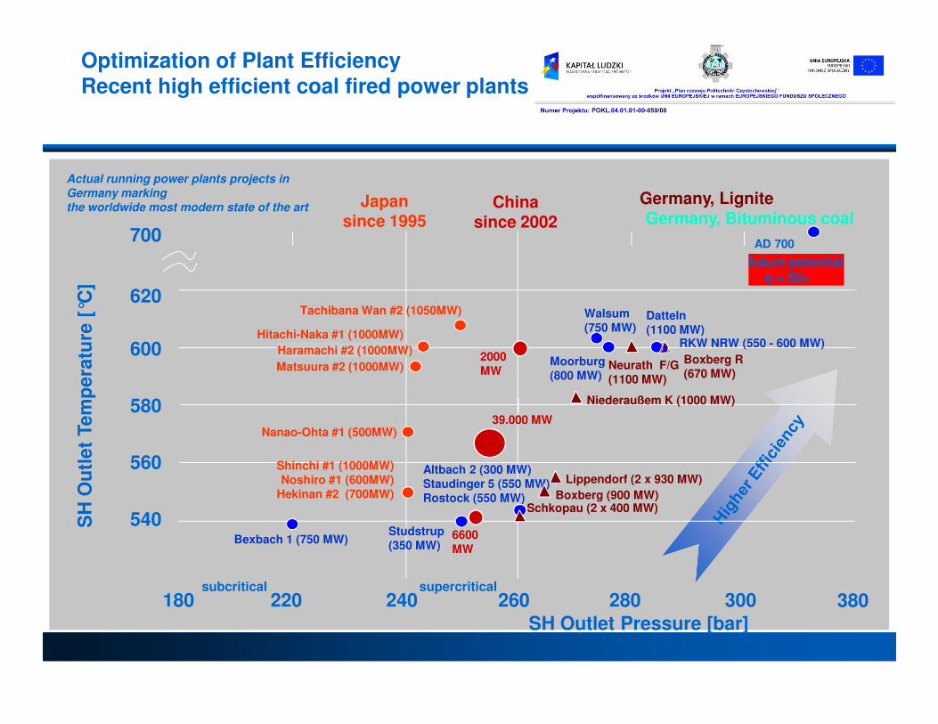
Actual running power plants projects in Germany marking the worldwide most modern state of the art
700
620
600Hitachi-Naka #1 (1000MW)
Tachibana Wan #2 (1050MW)
Matsuura #2 (1000MW)
Haramachi #2 (1000MW)
Japansince 1995
2000
Chinasince 2002
SH
Ou
tle
t Te
mp
era
ture
[°C
]
AD 700
future potentialηηηη = 50+
RKW NRW (550 - 600 MW)
Moorburg
Walsum(750 MW)
Datteln(1100 MW)
Germany, Bituminous coal
Neurath F/G
Germany, Lignite
Boxberg R
Optimization of Plant EfficiencyRecent high efficient coal fired power plants
180 220 240 260 280 300 380
580
560
540
Matsuura #2 (1000MW)
Shinchi #1 (1000MW)Noshiro #1 (600MW)
Hekinan #2 (700MW)
Nanao-Ohta #1 (500MW)
2000MW
39.000 MW
6600MW
SH
Ou
tle
t Te
mp
era
ture
[
SH Outlet Pressure [bar]
subcritical supercritical
Altbach 2 (300 MW)Staudinger 5 (550 MW) Rostock (550 MW)
Bexbach 1 (750 MW)Studstrup (350 MW)
Moorburg(800 MW)
Lippendorf (2 x 930 MW)
Niederaußem K (1000 MW)
Boxberg (900 MW)
Neurath F/G(1100 MW)
Schkopau (2 x 400 MW)
Boxberg R(670 MW)
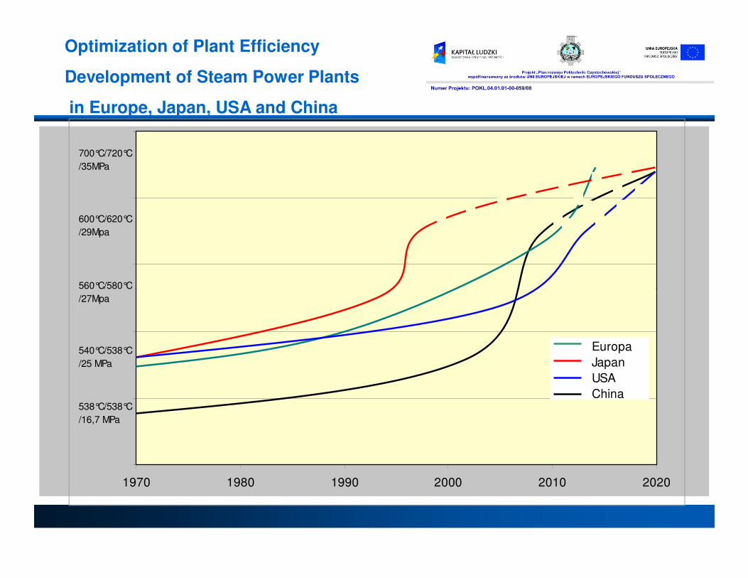
560°C/580°C
600°C/620°C
/29Mpa
700°C/720°C
/35MPa
Optimization of Plant Efficiency
Development of Steam Power Plants
in Europe, Japan, USA and China
1970 1980 1990 2000 2010 2020
Europa
Japan
USA
China538°C/538°C
/16,7 MPa
540°C/538°C
/25 MPa
560°C/580°C
/27Mpa

Jak poprawić sprawność kotła Jak poprawić sprawność kotła Jak poprawić sprawność kotła Jak poprawić sprawność kotła
300 bar600/600 C
double
0.03 bar
0.065 bar
45
44
43
Sprawność netto%
46
+1.5%
+1.5%
Poprawa sprawności
%
+3
+4
+5
Page 15
Nadmiar Temp gazów Parametry pary Przegrzew Ciśnienie powietrza wylotowych kondensacji
120
130
250 bar540/560 C
170 bar535/535 C
250 bar540/560 C
single43
42
41
40
39
1.15
1.250
+1
+2
+3

High plant High plant efficiencyefficiency
SupercriticalSupercritical steamsteam parametersparameters areare supportingsupporting COCO22 emissionemission reductionreduction andandfuelfuel savingssavings. .
EvolutionEvolution of of steamsteam parametersparameters inin steamsteam powerpower plantsplants
Average efficiency of coalAverage efficiency of coal--fired power plants in OECD countries fired power plants in OECD countries -- 37 %, 37 %, globally about 30 %.globally about 30 %.

High plant High plant efficiencyefficiency
EEach ach 1 %1 % increase in absolute efficiency in a coal firedincrease in absolute efficiency in a coal fired plant canplant canresult inresult in 3 % 3 % reductionreduction inin CO2 CO2 emmisionsemmisions ::
• Power unit with efficiency of 37 % generates 0,85 tonnes CO2/MWh
• Power unit with efficiency of 48 % generates 0,65 tonnes CO2/MWh
EachEach 1 %1 % increase in absolute efficiency in a coal firedincrease in absolute efficiency in a coal fired plant canplant canEachEach 1 %1 % increase in absolute efficiency in a coal firedincrease in absolute efficiency in a coal fired plant canplant canresult inresult in 2,4 % reduction2,4 % reduction inin fuelfuel costcost..
Łagisza unit Łagisza unit efficiencyefficiency isis 8.3 % 8.3 % betterbetter thanthan bestbest coalcoal firedfired powerpowerplantsplants inin Poland.Poland.
EachEach 1 % 1 % increaseincrease of unit of unit efficiencyefficiency inin Łagisza Łagisza resultresult inin savingssavings ofofapproximatelyapproximately 0.75 EUR/0.75 EUR/MWhMWh*. *.
* Coal price 40,2 EUR/ton, CO2 permit price 25 EUR/ton

How to improve efficiency

HowHow to to improveimprove efficiencyefficiency
Flue Flue Gas Heat RecoveryGas Heat Recovery
Rotary Air Preheater
ID-Fan
LP-Bypass Economize
r
M
LP-Preheaters
M
M
FW Tank
Flue gas temperature 85 °C
ESP
PA-FanSA-Fan
Heat Recovery CoolerAux. Steam
HeaterAir
Preheaters
MM
M
M
Flue gas temperature 85 °C
Improvement of 0.8 %-units in total plant
efficiency
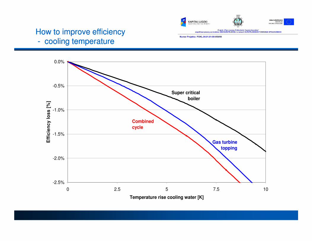
HowHow to to improveimprove efficiencyefficiency-- cooling temperaturecooling temperature
-1.0%
-0.5%
0.0%
Eff
icie
nc
y l
os
s [
%]
Super critical
boiler
Combined
-2.5%
-2.0%
-1.5%
0 2.5 5 7.5 10
Temperature rise cooling water [K]
Eff
icie
nc
y l
os
s [
%]
Gas turbine
topping
Combined
cycle
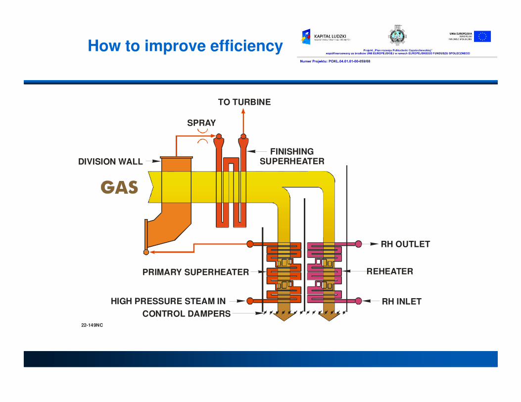
DIVISION WALL
SPRAY
FINISHINGSUPERHEATER
TO TURBINE
How to improve efficiency
RH OUTLET
RH INLET
REHEATERPRIMARY SUPERHEATER
CONTROL DAMPERS
HIGH PRESSURE STEAM IN
22-149NC

HowHow to to improveimprove efficiencyefficiency
-- sliding pressure sliding pressure op. op. modemode
Comparison of Typical Operation ModesBy adopting sliding pressure operation (more precisely, combined operation of constant and sliding pressure operation), plant efficiency becomes higher at partial load range.becomes higher at partial load range.- Higher HP turbine internal efficiency.- Less BFP power consumption.- Higher reheat steam temperature at partial load
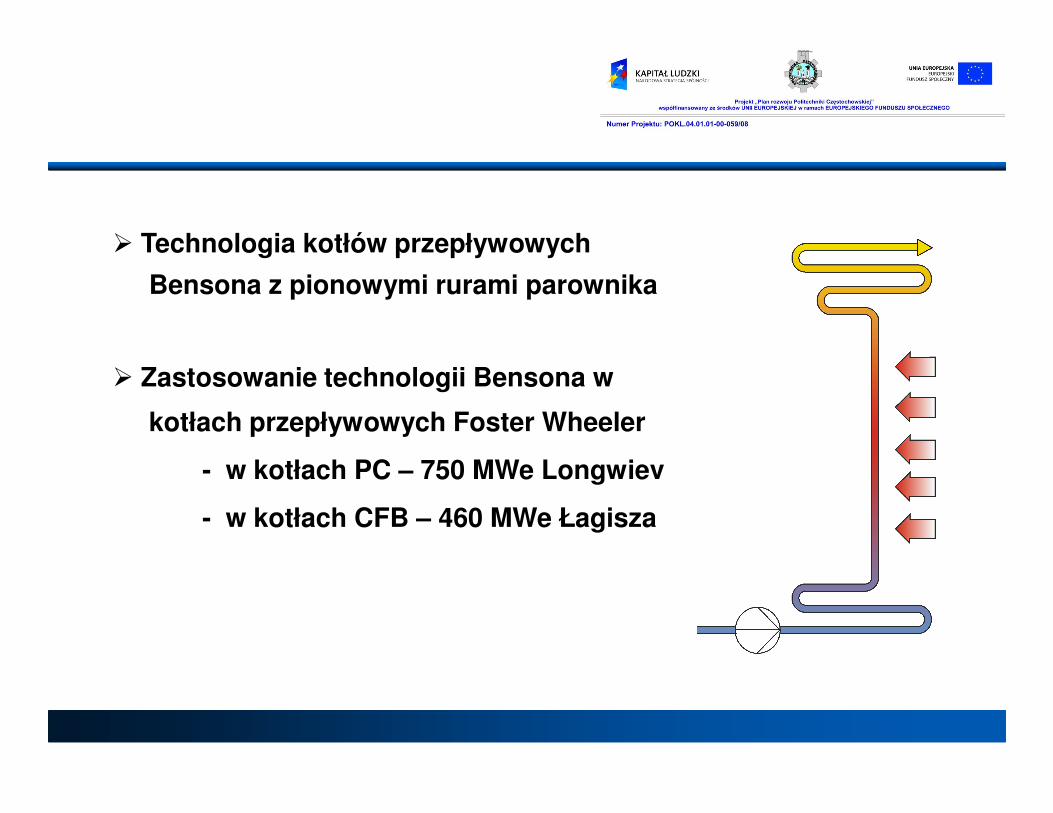
� Technologia kotłów przepływowych
Bensona z pionowymi rurami parownika
� Zastosowanie technologii Bensona w
kotłach przepływowych Foster Wheelerkotłach przepływowych Foster Wheeler
- w kotłach PC – 750 MWe Longwiev
- w kotłach CFB – 460 MWe Łagisza
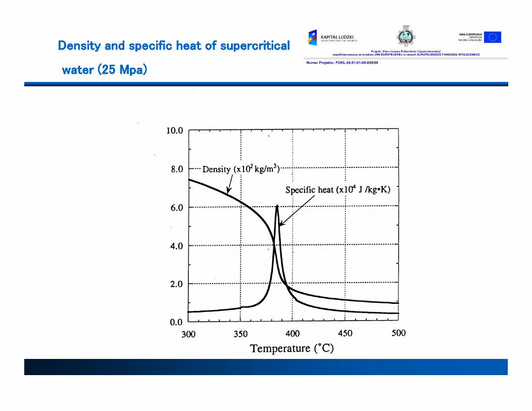
Density and specific heat Density and specific heat Density and specific heat Density and specific heat oooof supercritical f supercritical f supercritical f supercritical
water (25 water (25 water (25 water (25 MpaMpaMpaMpa))))

� Technologia kotłów przepływowych
Bensona z pionowymi rurami parownika
� Zastosowanie technologii Bensona w
kotłach przepływowych Foster Wheelerkotłach przepływowych Foster Wheeler
- w kotłach PC – 750 MWe Longwiev
- w kotłach CFB – 460 MWe Łagisza

Technologia kotłów przepływowychTechnologia kotłów przepływowych
•
Kotły na parametry nadkrytyczne mogą pracować
tylko jako kotły przepływowe.
Główna wyzwania projektowe :
• ochrona rur parownika przed przegrzaniem• ochrona rur parownika przed przegrzaniem
- kryzys wrzenia (wrzenie błonowe)
- praca rur „na sucho”
• ograniczenie różnic temperatur pomiędzy
poszczególnymi rurami ekranowymi
- konieczność przejęcia zróżnicowanego
obciążenia cieplnego

Technologia kotłów przepływowychTechnologia kotłów przepływowych

Technologia kotłów przepływowychTechnologia kotłów przepływowych
KOCIOŁ Z CYRKULACJĄ NATURALNĄ NA PARAMETRY PODKRYTYCZNE
Evaporation End PointIn subcritical units the drum acts as a fixed evaporation end point. The furnace water walls act as the evaporator. Not so in the case of a supercritical unit. The evaporation end point can occur in various levels of the furnace depending on the boiler load. The percentage of Superheat in supercritical units is higher than subcritical units. Because of this the furnace tubes act more as superheaters than waterwalls. This necessitates the use of higher grade of materials like alloy steels in the furnace.
KOCIOŁ PRZEPŁYWOWY NA PARAMETRY NADKRYTYCZNE
Naprężenia termiczne

Technologia kotłów przepływowychTechnologia kotłów przepływowych
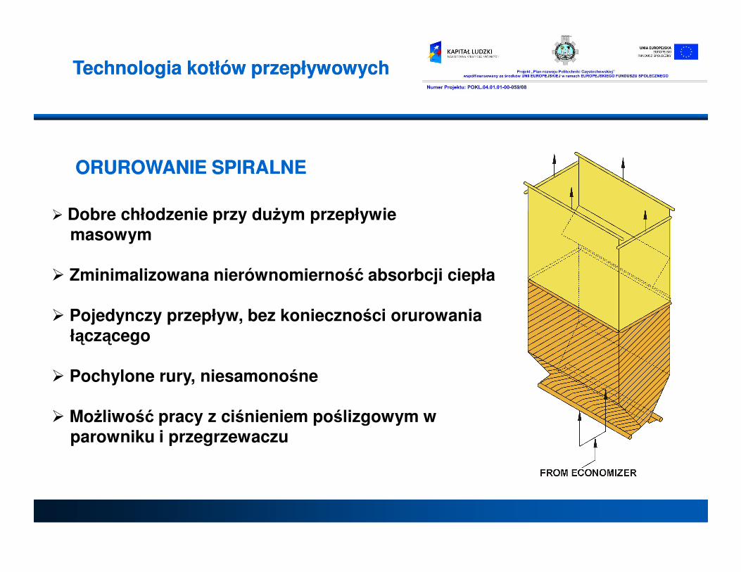
� Dobre chłodzenie przy dużym przepływiemasowym
� Zminimalizowana nierównomierność absorbcji ciepła
ORUROWANIE ORUROWANIE SPIRALSPIRALNENE
Technologia kotłów przepływowychTechnologia kotłów przepływowych
� Pojedynczy przepływ, bez konieczności orurowaniałączącego
� Pochylone rury, niesamonośne
� Możliwość pracy z ciśnieniem poślizgowym w parowniku i przegrzewaczu
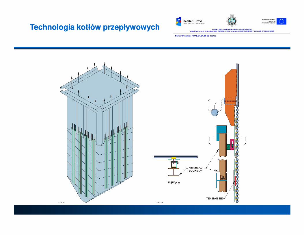
Technologia kotłów przepływowychTechnologia kotłów przepływowych

Technologia kotłów przepływowychTechnologia kotłów przepływowych
ProProstszystszy, , standardowy system zawieszeństandardowy system zawieszeń

Technologia kotłów Technologia kotłów przepływowychprzepływowych
WYSOKI PRZEPŁYW MASOWY(TYPOWE KOTŁY PRZEPŁYWOWE)
(OKOŁO 1800 kg/m2s)
SPADEK CISNIENIA PRZY STAŁYM PRZEPŁYWIE MASOWYM
NISKI PRZEPŁYW MASOWY(ORUROWANIE PIONOWE BENSON)
(OKOŁO 300 – 1000 kg/m2s)
SPADEK CISNIENIA PRZY STAŁYM PRZEPŁYWIE MASOWYM
SPADEK CISNIENIA JEST JEDNAKOWY WE WSZYSTKICH RURACH: STRUMIEŃ MASOWY
CZYNNIKA MALEJE W RURZE NADMIERNIE
OGRZEWANEJ
RURA OGRZEWANA NOMINALNIE
RURA NADMIERNIE OGRZEWANA
OPORY
PRZEPŁYWU
CIŚNIENIE HYDROSTATYCZNE
RURA OGRZEWANA NOMINALNIE
OPORY PRZEPŁYWU
CIŚNIENIE HYDROSTATYCZNE
RURA NADMIERNIE OGRZEWANA
SPADEK CISNIENIA JEST JEDNAKOWY WE WSZYSTKICH RURACH: STRUMIEŃ MASOWY
CZYNNIKA WZRASTA W
RURZE NADMIERNIE OGRZEWANEJ

M = Water flow, kg/sQ = Heat absorbed by tube, kWA = Total tube flow area, m2Water mass flow = M/A, kg/sqm/sResponse ratio = (dM/M)/(dQ/Q)The optimum water mass flow rate is obtained by selecting rate is obtained by selecting the right combination of water flow, tube size and pitching.

BENSON VERTICAL TUBE DESIGNBENSON VERTICAL TUBE DESIGNReduces Auxiliary Power with Low Reduces Auxiliary Power with Low Pressure Pressure LossesLosses
300
400
500
600
700620
515
390330
*Frictional Pressure Loss (psi)
NOTE: * Static head not included
** BENSON Load
Multi-Pass Spiral 25** Spiral 40** BENSON Vertical0
100
200
300
Economizer Evaporator Superheater
psi psi –– poundpound//sqsq inchinch100 psi = 6,895bar100 psi = 6,895bar

Technologia kotłów przepływowychTechnologia kotłów przepływowych
Rury żebrowane są efektywniej chłodzoneRury żebrowane są efektywniej chłodzone

PIONOWY PAROWNIK PIONOWY PAROWNIK BENSONBENSONAA
Technologia kotłów przepływowychTechnologia kotłów przepływowych
Technologia kotłów przepływowychTechnologia kotłów przepływowych
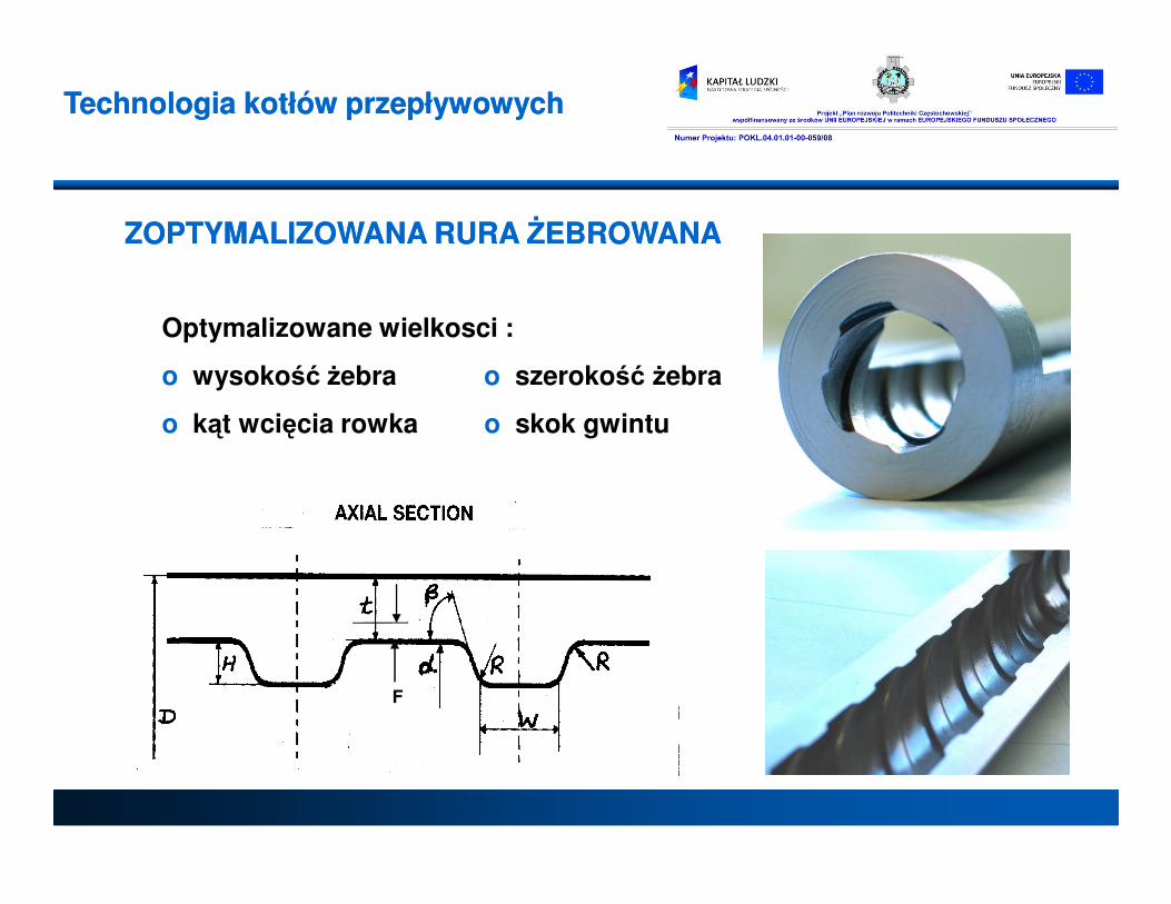
Optymalizowane wielkosci :
o wysokość żebra o szerokość żebra
o kąt wcięcia rowka o skok gwintu
ZOPTYMALIZOWANA RURA ŻEBROWANAZOPTYMALIZOWANA RURA ŻEBROWANA
F

OPTIMIZED RIFLED TUBESOPTIMIZED RIFLED TUBESAllows Low Mass Flux for Allows Low Mass Flux for ““Natural Circulation” CharacteristicNatural Circulation” Characteristic
• E xten sive tes tin g do ne to d efine o p tim um riflin g co n figuration
• O ptim um rifling (lead ang le , rib h e igh t, corn er rou nd in g to le rances) p ro vides:to le rances) p ro vides:
– be tte r tube coo ling fo r the
sam e m ass flux , o r
– low er m ass flux fo r the sam e
tube coo ling
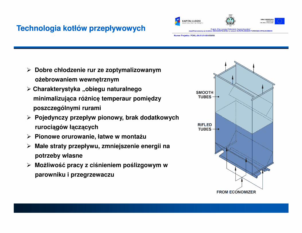
� Dobre chłodzenie rur ze zoptymalizowanym
ożebrowaniem wewnętrznym
� Charakterystyka „obiegu naturalnego
minimalizująca różnicę temperaur pomiędzy
poszczególnymi rurami
� Pojedynczy przepływ pionowy, brak dodatkowych
Technologia kotłów przepływowychTechnologia kotłów przepływowych
� Pojedynczy przepływ pionowy, brak dodatkowych
rurociągów łączących
� Pionowe orurowanie, łatwe w montażu
� Małe straty przepływu, zmniejszenie energii na
potrzeby własne
� Możliwość pracy z ciśnieniem poślizgowym w
parowniku i przegrzewaczu
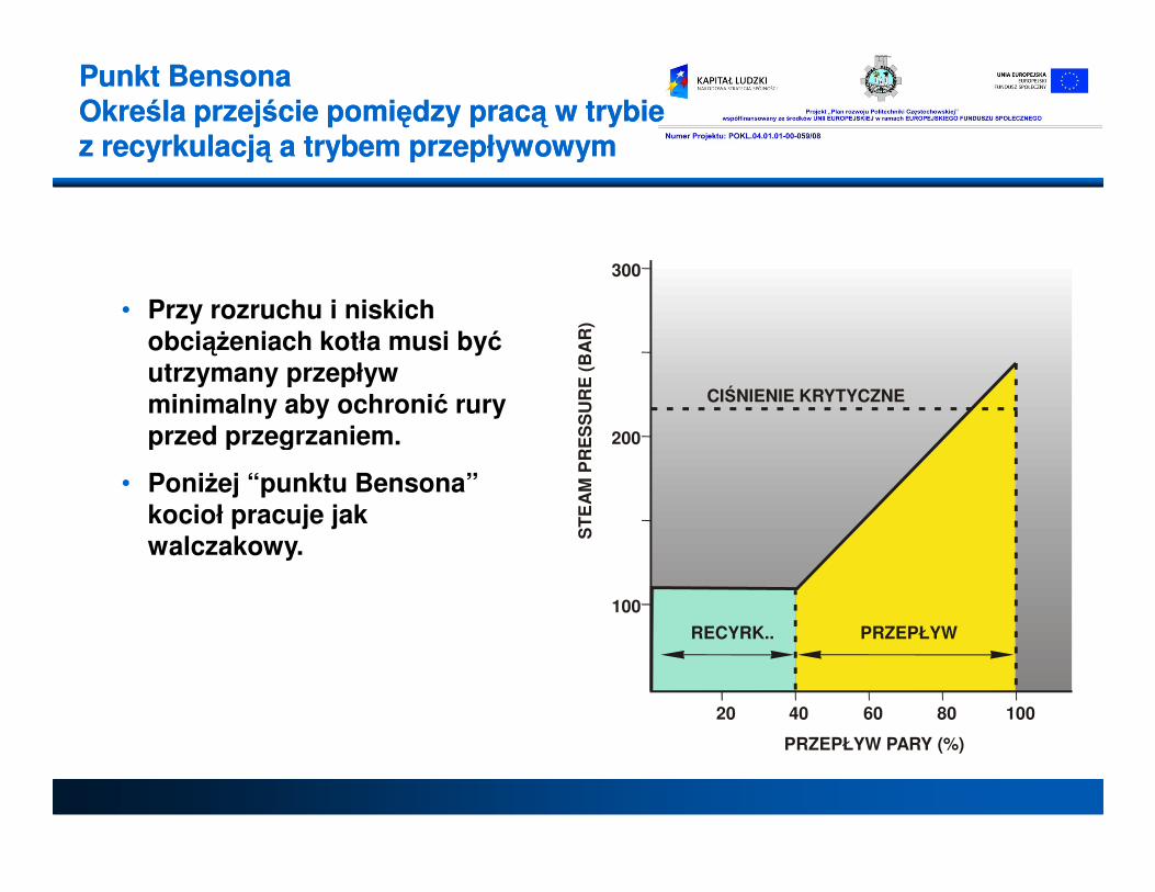
Punkt Punkt BensonBensonaaOkreśla przejście pomiędzy pracą w trybie Określa przejście pomiędzy pracą w trybie z z recyrkulacją a trybem przepływowymrecyrkulacją a trybem przepływowym
200
300
ES
SU
RE
(BA
R)
CIŚNIENIE KRYTYCZNE
• Przy rozruchu i niskich obciążeniach kotła musi być utrzymany przepływ minimalny aby ochronić rury przed przegrzaniem.
100
200
20 40 60 80 100
ST
EA
MP
RE
PRZEPŁYW PARY (%)
RECYRK.. PRZEPŁYW
przed przegrzaniem.
• Poniżej “punktu Bensona” kocioł pracuje jak walczakowy.

Pompa recyrkulacyjnaPompa recyrkulacyjnaPracuje w trakcie rozruchu Pracuje w trakcie rozruchu i i przy niskich obciążeniachprzy niskich obciążeniach

BENSON BOILER BENSON BOILER System rozruchowySystem rozruchowy
Odśrodkowy separator

� Technologia kotłów przepływowych
Bensona z pionowymi rurami parownika
� Zastosowanie technologii Bensona w
kotłach przepływowych Foster Wheelerkotłach przepływowych Foster Wheeler
- w kotłach PC – 750 MWe Longwiev
- w kotłach CFB – 460 MWe Łagisza
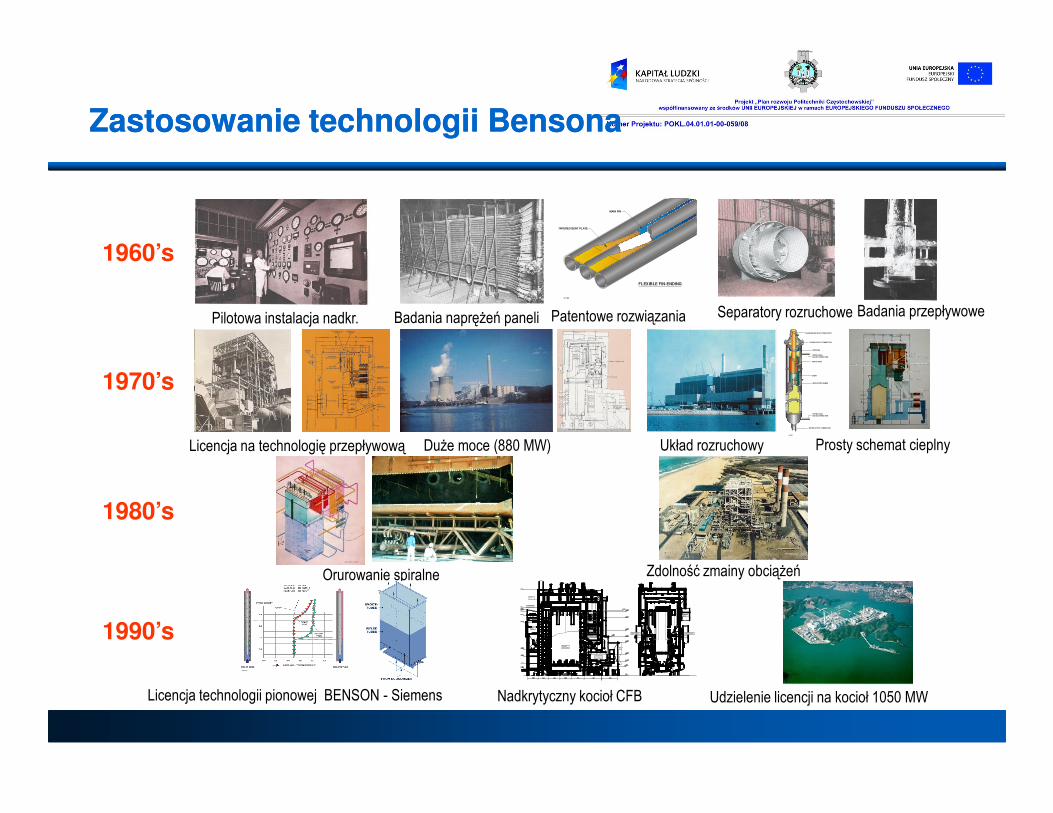
Zastosowanie technologii BensonaZastosowanie technologii Bensona
Pilotowa instalacja nadkr. Badania naprężeń paneli
31-184
MAIN FIN
TAPERED BENT PLATE
FLEXIBLE FIN-ENDING
Patentowe rozwiązania Separatory rozruchowe Badania przepływowe
1960’s
1970’s
STEAM/WATER INLET CONNECTION
STEAM OUTLET CONNECTION
DRIP RING
UPPER LEVELGAUGE CONNECTION
SPIRAL ARM
SKIRT
ANTI-VORTEX VANES
33-288
LOWER LEVELGAUGE CONNECTION
WATER OUTLET CONNECTION
Licencja na technologię przepływową Duże moce (880 MW) Układ rozruchowy Prosty schemat cieplny
1980’s
Orurowanie spiralne Zdolność zmainy obciążeń
1990’s
Licencja technologii pionowej BENSON - Siemens
FURNACE22042 X 10074
RH I
STEAM DRUM
HOIST
COAL SILOS
RH II
ECO
TUBULARAIR PREHEATER
AIR PREHEATER
ESP
LIMESTONE SILO
CONVEYOR
BRIDGE
LIMESTONE SILO
Nadkrytyczny kocioł CFB Udzielenie licencji na kocioł 1050 MW

Kocioł Taishan 600 MWe OTU Studium 600 MWe CFB OTU
2000 2001 - Present 20022000
Badania materiałowe dla Projekt Lagisza 460 MWe CFB
Zastosowanie technologii BensonaZastosowanie technologii Bensona
Kocioł Taishan 600 MWe OTU
(Projekt unieważniony)
Studium 600 MWe CFB OTU
dla EdF
2004 2006 2006 2007
Badania materiałowe dla
DOE Projekt Lagisza 460 MWe CFB
OTU Sold
Studium 800 MWe CFB OTU
dla EdF
Studium 400/800 MWe Ultra-
Superc.l CFB OTU dla DOE
Licencja FW Arch/BENSON
Vertical OTU
Projekt Longview 750 MWe PC OTU
(1st Supercritical BENSON Vertical OTU)

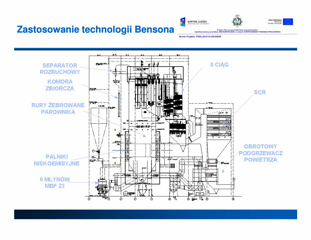
Zastosowanie technologii BensonaZastosowanie technologii Bensona
LOKALIZACJA:
Maidsville, West Virginia, USA
KLIENT:
Longview Power LLC
TECHNOLOGIA:
Kocioł pyłowy, przepływowy z pionowym parownikiem Bensona opalany węglem kamiennym wyposażony w palniki niskoemisyjne i SCR
Projekt Longview
węglem kamiennym wyposażony w palniki niskoemisyjne i SCR
HARMONOGRAM PROJEKTU:
Podpisanie kontraktu 02.2007
Rozpoczęcie prac 03.2007
Przekazanie do eksploatacji 03.2011
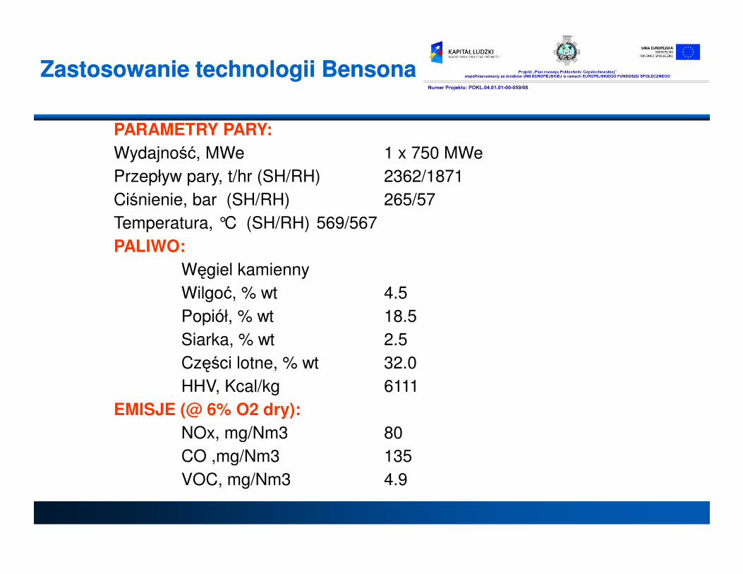
Zastosowanie technologii BensonaZastosowanie technologii Bensona
PARAMETRY PARY:
Wydajność, MWe 1 x 750 MWe
Przepływ pary, t/hr (SH/RH) 2362/1871
Ciśnienie, bar (SH/RH) 265/57
Temperatura, °C (SH/RH) 569/567
PALIWO:
Węgiel kamienny
Wilgoć, % wt 4.5Wilgoć, % wt 4.5
Popiół, % wt 18.5
Siarka, % wt 2.5
Części lotne, % wt 32.0
HHV, Kcal/kg 6111
EMISJE (@ 6% O2 dry):
NOx, mg/Nm3 80
CO ,mg/Nm3 135
VOC, mg/Nm3 4.9
Zastosowanie technologii BensonaZastosowanie technologii Bensona
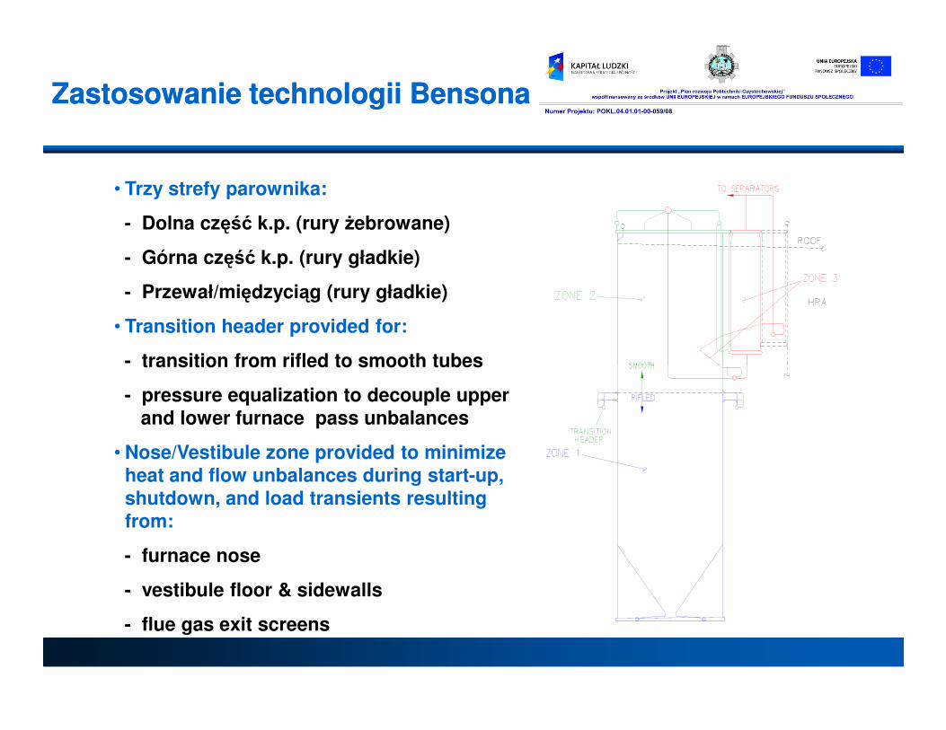
• Trzy strefy parownika:
- Dolna część k.p. (rury żebrowane)
- Górna część k.p. (rury gładkie)
- Przewał/międzyciąg (rury gładkie)
• Transition header provided for:
- transition from rifled to smooth tubes
Zastosowanie technologii BensonaZastosowanie technologii Bensona
- transition from rifled to smooth tubes
- pressure equalization to decouple upperand lower furnace pass unbalances
• Nose/Vestibule zone provided to minimize heat and flow unbalances during start-up, shutdown, and load transients resulting from:
- furnace nose
- vestibule floor & sidewalls
- flue gas exit screens

Metody regulacji temperatury pary wtórnej
Reheat Control Methods
-1.00
-0.50
0.00
Net
Cycle
Eff
icie
ncy
%
Reheat Spay
Gas Recycle
T
Metody regulacji przegrzewu wtórnego
ść o
bie
gu
nett
o %
Wtrysk wody
Recyrkulacja spalin
Page 51
-2.50
-2.00
-1.50
40 50 60 70 80 90 100
Boiler Load %
Net
Cycle
Eff
icie
ncy
%
Gas Recycle
Parallel Gas Flow
Obciążenie kotła %
Sp
raw
ność
ob
ieg
u n
ett
o %
Recyrkulacja spalin
Przepływ równoległy spalin

Benson Benson verticalvertical lowlow mass mass
fluxflux technologytechnology
• self supporting vertical tubing evaporator
• „natural circulation” characteristic limits
differential tubes temperatures
• lower erosion in furnace and lower manufacturing
costs compare to the typical spiral wound
RIFLED TUBESSMOOTH TUBES
costs compare to the typical spiral wound
OTU design
• low evaporator pressure loss reduces
axualiry power consumption
• effective tube cooling with optimized
rifled tubing
• can operat with full variable pressure
in evaporator and superheater
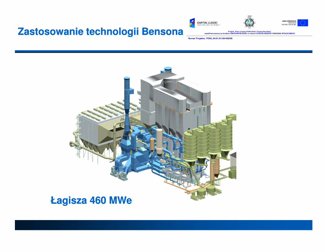
Zastosowanie technologii BensonaZastosowanie technologii Bensona
ŁŁagisza 460 MWeagisza 460 MWe

Dziękuję za uwagę Dziękuję za uwagę