Installation uide RAV (25-65 C / 35-5 C) - Danfoss...
4
1 Installation Guide RAVK (25-65 °C / 35-75 °C) District Energy VI.52.H9.2Z DEN-SMT/SI ENGLISH RAVK www.danfoss.com Page 4 POLSKI RAVK www.danfoss.com Page 4
Transcript of Installation uide RAV (25-65 C / 35-5 C) - Danfoss...

1
Installation Guide
RAVK (25-65 °C / 35-75 °C)
District Energy VI.52.H9.2Z DEN-SMT/SI
ENGLISH RAVK www.danfoss.com Page 4
POLSKI RAVK www.danfoss.com Page 4
2
Installation Guide RAVK (25-65 °C / 35-75 °C)
DEN-SMT/SI VI.52.H9.2Z District Energy
②
③
❶
❷
①
RAVK
max
. 90/
120/
130
o C
25 - 65 oC
10oC
25 - 65 oCmax. 90/120/130 oC
RAVK
25 - 65 oC
max
. 90/
120/
130
o C
10oC
min. 1 2 3 4 5 max.
(25…65 °C) 25 35 45 55 65 °C
❹❸
min. 1 2 3 4 5 max.
30 40 52 64 76 °C(35...75 °C)

33
Installation Guide RAVK (25-65 °C / 35-75 °C)
District Energy VI.52.H9.2Z DEN-SMT/SI
1a 2a 3a
1b/2b/3b
1c
1d
2c
2d
3c
3d
❺

Installation Guide RAVK (25-65 °C / 35-75 °C)
73693047/VI.52.H9.2Z Produced by Danfoss A/S © 11/2014
ENGLISH
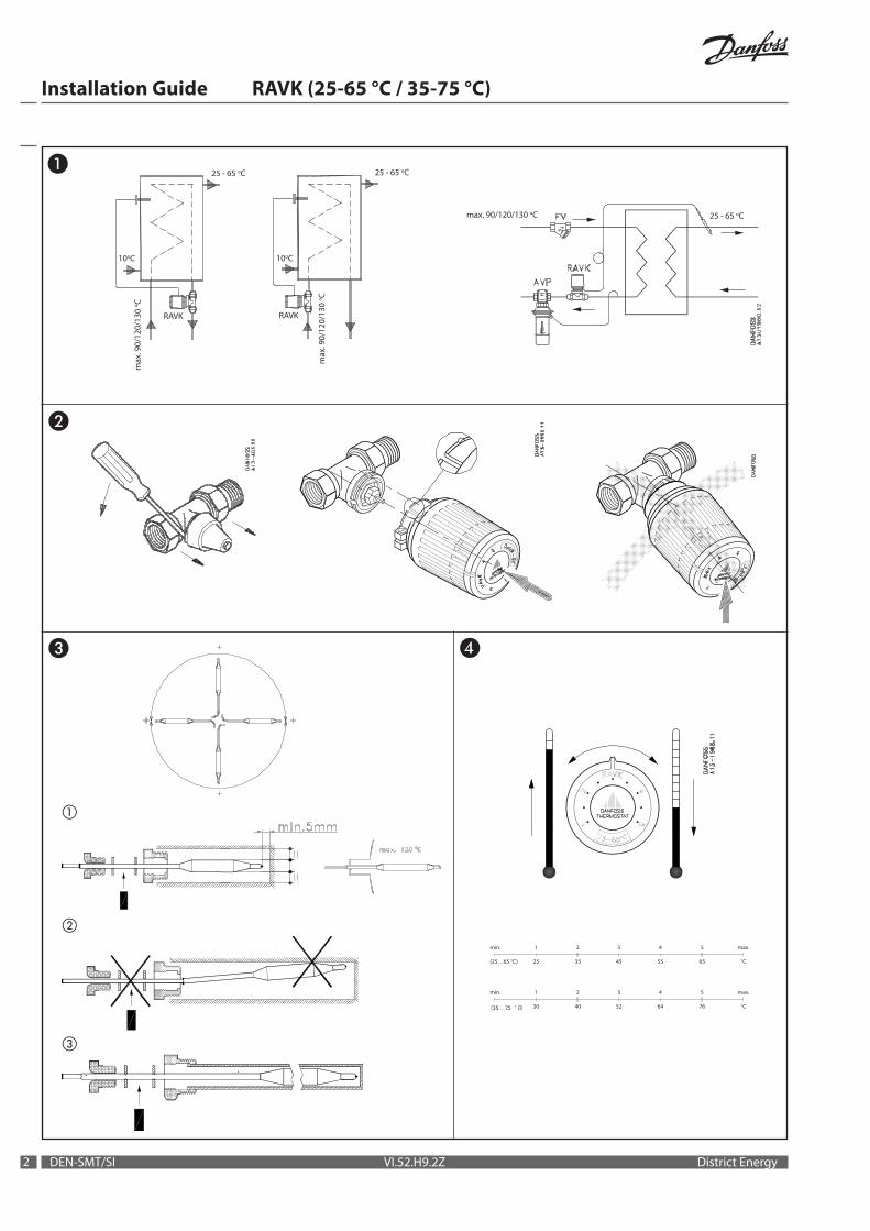
Fitting ❶
Install sensor ❸• Install sensor part as shown on fig. ①
in order to assure at least 5 mm distance between sensor housing made of brass and other metal parts.
• Consider adequate distance over the whole side length and end part of the sensor (fig. ①).
• Assure that sensor is properly fixed; larger dimension of capillary tube has to be fixed with stuffing box (2 washers with rubber gasket in between, tightened with screw), (fig. ①).
POLSKI
Montaż ❶
Zamontuj czujnik ❸• Zamontuj czujnik tak jak pokazano na
Rys. ① zachowując 5 mm odległości pomiędzy czujnikiem i obudową wykonaną z mosiądzu lub innymi metalowymi elementami.
• Oszacuj odpowiednią odległość porównując długość całkowitą i końcówkę czujnika (Rys. ①).
• Upewnij się, że czujnik jest prawidłowo ustalony; uszczelnić zestawem uszczelniającym na większej średnicy rurki kapilarnej (2 podkładki z gumową uszczelką pomiędzy, ściągnięte śrubą ), (Rys. ①).
• By installation shown on figure ① you also assure the optimal arm (distance between stuffing box where sensor is fixed and end part of the sensors inserted in the media in heat exchanger or boiler) which will reduce the risk of vibrations which could cause a metal contact.
• Please avoid installation which is shown on figure ② (thinner diameter of capillary tube fits in stuffing box, longer arm etc.).
• If you can not avoid or at least you assume the possibility of metal contact, than you have to use a protecting pocket (sleeve) made of stainless steel (figure ③).
By using this standard type of accessory you will be faced with longer response time of RAV’s performance due to slower heat transition.
Setting ❹
Limiting or locking of setting range ❺
• Przy montażu pokazanym na Rys. ① sprawdź czy czujnik jest zanurzony optymalnie (odległość końca czujnika zanurzonego w czynniku w wymienniku lub podgrzewaczu od jego miejsca stałego zamocowania w zestawie uszczelniającym ) co zmniejszy ryzyko wzbudzenia wibracji, które mogą grozić kontaktem czujnika z metalem.
• Należy unikać montażu pokazanego na Rys. ② (cieńsza średnica rurki kapilarnej na wysokości uszczelnienia, dłuższe ramie itp.).
• Jeżeli nie można tego uniknąć, lub oceniasz zagrożenie wystąpienia kontaktu z częściami metalowymi, konieczne jest użycie tulei ochronnej (kieszeni) ze stali nierdzewnej (Rys. ③).
Przy zastosowaniu tego typu standardowych akcesoriów wydłuży się czas reakcji regulatora RAV spowodowany wolniejszym przewodzeniem ciepła.
Nastawa ❹
Ograniczanie lub blokowanie zakresu nastawy ❺
![Installation of partition wall systems 712[06].S1.02](https://static.fdocuments.pl/doc/165x107/5880affc1a28ab74298c6016/installation-of-partition-wall-systems-71206s102.jpg)


![Installation of partition wall systems 712[06].S1](https://static.fdocuments.pl/doc/165x107/620730ad49d709492c2ed15b/installation-of-partition-wall-systems-71206s1.jpg)