Gui Del 22
26
GUIDELINES FOR SOLAR PHOTOVOLTAIC SYSTEMS FOR AIDS TO NAVIGATION DECEMBER 2001 IALA / AISM – 20ter rue Schnapper – 78100 Saint Germain en Laye – France Tel : +33 1 34 51 70 01 – Fax : +33 1 34 51 82 05 – E-mail : [email protected] Internet : www.iala-aism.org
-
Upload
kalki-muruganandam -
Category
Documents
-
view
220 -
download
0
Transcript of Gui Del 22

8/3/2019 Gui Del 22
http://slidepdf.com/reader/full/gui-del-22 1/26
GUIDELINESFOR
SOLAR PHOTOVOLTAIC SYSTEMS

8/3/2019 Gui Del 22
http://slidepdf.com/reader/full/gui-del-22 2/26

8/3/2019 Gui Del 22
http://slidepdf.com/reader/full/gui-del-22 3/26
TABLE OF CONTENTS
1 INTRODUCTION..................................................................................................................5
2 GENERAL CONSIDERATIONS..........................................................................................5 2.1 CONVERSION OF EXISTING LIGHTS TO PV ENERGY .............................................................5 2.2 PV MODULE TECHNOLOGY ...............................................................................................6 2.3 MODULAR DESIGN CONSIDERATIONS.................................................................................6
2.3.1 Example of a modular design concept...........................................................................6 2.4 BACKUP ENERGY SOURCES ...............................................................................................6
3 CALCULATING THE TOTAL ELECTRICAL LOAD........ ......... ........ ......... ........ ......... ..... 6 3.1 LOAD OPERATING TIMES...................................................................................................7
3.1.1 Photo-sensors..............................................................................................................7 3.2 IDLING CURRENT.............................................................................................................. 7 3.3 FOG EFFECTS ON POWER CONSUMPTION ............................................................................7 3.4 RACONS.......................................................................................................................... 7 3.5 FOG SIGNALS ...................................................................................................................7
3.6 REMOTE CONTROL AND MONITORING SYSTEMS..................................................................7 3.7 OTHER LOADS..................................................................................................................8 3.8 TYPICAL LOAD LEVELS ..................................................................................................... 8
4 DESIGNING THE SOLAR POWER SYSTEM........... ......... ........ ......... ........ ......... ........ ..... 11 4.1 GENERAL CONSIDERATIONS............................................................................................ 11 4.2 COMPUTER PROGRAMS................................................................................................... 11 4.3 PV ENERGY ON BUOYS ................................................................................................... 11 4.4 AVAILABILITY OF COMPUTER PROGRAMMES.................................................................... 12
5 BATTERIES FOR PV ENERGY SYSTEMS 12
8/3/2019 Gui Del 22
http://slidepdf.com/reader/full/gui-del-22 4/26
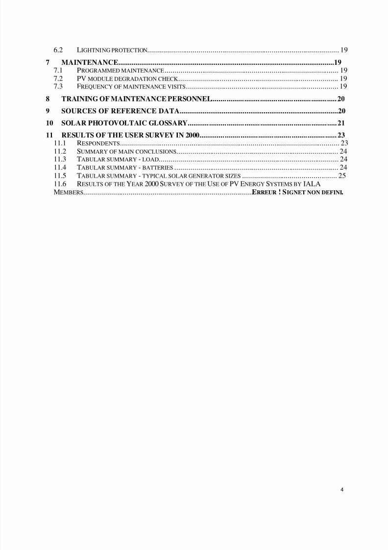
6.2 LIGHTNING PROTECTION................................................................................................. 19
7 MAINTENANCE.................................................................................................................19 7.1 PROGRAMMED MAINTENANCE ........................................................................................ 19 7.2 PV MODULE DEGRADATION CHECK................................................................................. 19 7.3 FREQUENCY OF MAINTENANCE VISITS ............................................................................. 19
8 TRAINING OF MAINTENANCE PERSONNEL........ ......... ........ ......... ........ ......... ........ ..... 20
9 SOURCES OF REFERENCE DATA...................................................................................20
10 SOLAR PHOTOVOLTAIC GLOSSARY........... ......... ......... ........ ......... ........ ......... ........ ..... 21
11 RESULTS OF THE USER SURVEY IN 2000............. ........ ......... ........ ......... ........ ......... ...... 23 11.1 RESPONDENTS............................................................................................................... 23 11.2 SUMMARY OF MAIN CONCLUSIONS.................................................................................. 24 11.3 TABULAR SUMMARY - LOAD........................................................................................... 24 11.4 TABULAR SUMMARY - BATTERIES ................................................................................... 24 11.5 TABULAR SUMMARY - TYPICAL SOLAR GENERATOR SIZES ................................................ 25 11.6 RESULTS OF THE YEAR 2000 SURVEY OF THE USE OF PV ENERGY SYSTEMS BY IALA
MEMBERS.......................................................................................ERREUR ! SIGNET NON DEFINI.

8/3/2019 Gui Del 22
http://slidepdf.com/reader/full/gui-del-22 5/26
1 INTRODUCTION
A large number of services involved in marine aids to navigation (AtoN) are increasingly familiarwith solar energy systems, and know that Photo Voltaic (PV) energy is an excellent technical andeconomic choice for powering many AtoN.
In order to have the best results with PV energy, it is of prime importance to size, to install, to operate,
and to mainta in the solar PV system correctly. This document can be used as an introduction to theapplication of PV energy systems to AtoN. It should be read in conjunction with other IALApublications that are listed in the reference section.
Readers should also bear in mind that PV systems continue to develop, and so they should endeavourto keep abreast of the latest technology.
Included at the end of this document are summaries of the replies from a wide range of countries toquestionnaires circulated to IALA members in 2000, on the subjects of energy sources.
2 GENERAL CONSIDERATIONS
An AtoN PV power system in its simplest form consists of a solar panel and a secondary battery. Acharge regulator may also be used. PV power systems are a well-proven technology and equipment is
8/3/2019 Gui Del 22
http://slidepdf.com/reader/full/gui-del-22 6/26
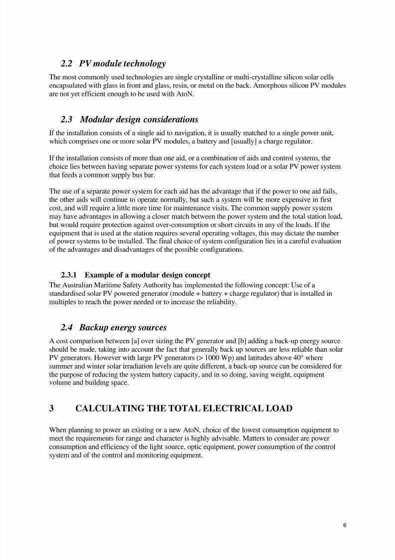
2.2 PV module technology
The most commonly used technologies are single crystalline or multi-crystalline silicon solar cellsencapsulated with glass in front and glass, resin, or metal on the back. Amorphous silicon PV modulesare not yet efficient enough to be used with AtoN.
2.3 Modular design considerations
If the installation consists of a single aid to navigation, it is usually matched to a single power unit,which comprises one or more solar PV modules, a battery and [usually] a charge regulator.
If the installation consists of more than one aid, or a combination of aids and control systems, thechoice lies between having separate power systems for each system load or a solar PV power systemthat feeds a common supply bus bar.
The use of a separate power system for each aid has the advantage that if the power to one aid fails,the other aids will continue to operate normally, but such a system will be more expensive in first
cost, and will require a little more time for maintenance visits. The common supply power systemmay have advantages in allowing a closer match between the power system and the total station load,but would require protection against over-consumption or short circuits in any of the loads. If theequipment that is used at the station requires several operating voltages, this may dictate the numberof power systems to be installed. The final choice of system configuration lies in a careful evaluationof the advantages and disadvantages of the possible configurations.
2 3 1 E l f d l d i t
8/3/2019 Gui Del 22
http://slidepdf.com/reader/full/gui-del-22 7/26
3.1 Load operating times
The first task in establishing the total electrical load is to estimate the length of time that each loadwill be operating. Estimating the length of time that a load is operating must be done precisely,because if it is in operation only at night, the length of operating time will vary with the seasons. Onesmall error in estimating time will be cumulative day after day, magnifying the error over the year.This can be critical for installations at high latitudes, but is usually not so important at lower latitudes.The design should ensure that switching devices turn the light on and off at the correct light levels tomatch the light-on periods used in the solar sizing programme. At higher latitudes there will be a
marked seasonal effect on light-on periods.
3.1.1 Photo-sensors
Note that a photodiode (a solar module or separate cell) is more stable than photo resistors, which intime can drift in characteristics, altering the light-on period, and thus adversely affecting the overallpower consumption.
If detailed information is not available, the "worst case" situation can be considered and the systemdesigned for the longest winter night.Estimates for flashed light signal loads must account for the surge current that occurs when heating acold lamp filament; this will increase the Ah/day consumption. Tables and formulae are available.
3.2 Idling current
Energy efficiency becomes very important in the higher latitudes. For example 5-mA idle current fora lantern during daytime does not seem much, but for autonomy period of 60 days about 7-Ah extra
8/3/2019 Gui Del 22
http://slidepdf.com/reader/full/gui-del-22 8/26
and excessive operator-instigated requests for data from a single out-station can cause the energy
drain to exceed the design parameters].
3.7 Other loads
Non-essential loads such as domestic lighting must be under some form of automatic control to ensurethat they cannot be left on and drain the power system.Solar sizing programmes usually require loads to be divided into day only, night only and continuous
load at different levels of power consumption. Most AtoN lights normally operate only during thenight time.
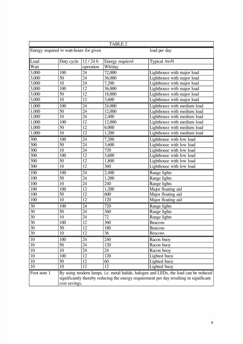
3.8 Typical load levels
The following two tables are taken from the IALA Guideline, produced following the workshop heldat Koblenz, Germany in 2001, on new light and energy sources. [Refer to list of references.] Theyserve to give a guide to typical load levels, and to indicate which load levels allow the use of PV
energy.
8/3/2019 Gui Del 22
http://slidepdf.com/reader/full/gui-del-22 9/26
TABLE 2Energy required in watt-hours for given load per day
Load Duty cycle 12 / 24 h Energy required Typical AtoNWatt operation Wh/day3,000 100 24 72,000 Lighthouse with major load3,000 50 24 36,000 Lighthouse with major load
3,000 10 24 7,200 Lighthouse with major load3,000 100 12 36,000 Lighthouse with major load3,000 50 12 18,000 Lighthouse with major load3,000 10 12 3,600 Lighthouse with major load
1,000 100 24 24,000 Lighthouse with medium load1,000 50 24 12,000 Lighthouse with medium load1,000 10 24 2,400 Lighthouse with medium load1,000 100 12 12,000 Lighthouse with medium load
1,000 50 12 6,000 Lighthouse with medium load1,000 10 12 1,200 Lighthouse with medium load
300 100 24 7,200 Lighthouse with low load300 50 24 3,600 Lighthouse with low load300 10 24 720 Lighthouse with low load300 100 12 3,600 Lighthouse with low load300 50 12 1,800 Lighthouse with low load300 10 12 360 Lighthouse with low load

8/3/2019 Gui Del 22
http://slidepdf.com/reader/full/gui-del-22 10/26
10
TABLE 3 – Recommended energy source for Aids to Navigation sited at various latitudes
Requiredenergy/day
LatitudeDegrees
Autonomy,
daysRecommendedenergy source
Battery capacity Batterytype
Approximatebattery cost
Comment
Watt-Hour Wh USD ($)
10,000 0 Diesel generator - - Autonomy depends on time to repair10,000 40 Diesel generator - - Autonomy depends on time to repair10,000 70 Diesel generator - - Autonomy depends on time to repair
3,000 0 5 Solar 15,000 Lead acid 3,7503,000 40 Diesel generator - Lead acid - Autonomy depends on time to repair3,000 70 Diesel generator - NiCd - Autonomy depends on time to repair
1,000 0 5 Solar 5,000 Lead acid 1,2501,000 40 20 Solar 20,000 Lead acid 5,0001,000 70 Diesel generator - NiCd - Autonomy depends on time to repair
300 0 5 Solar 1,500 Lead acid 375300 40 20 Solar 6,000 Lead acid 1,500
300 70 120 Solar 36,000 NiCd 36,000100 0 5 Solar 500 Lead acid 125100 40 20 Solar 2,000 Lead acid 500100 70 120 Solar 12,000 NiCd 12,00030 0 5 Solar 150 Lead acid 3830 40 20 Solar 600 Lead acid 15030 70 120 Solar 3,600 NiCd 3,600 Foot note 2
10 0 5 Solar 50 Lead acid 1310 40 20 Solar 200 Lead acid 5010 70 120 Solar 1,200 NiCd 1,200
Foot notes1 In all cases, if mains is available, it would be the preferable choice2 The choice of NiCd is essential due to low temperature3 For solar AtoN the autonomy includes the battery capacity designed to cover the longest "no sun" period plus (in the case of large "monitored" AtoN) the
time to reach the site to complete a repair (MTTR). For diesel powered AtoN the battery autonomy is only the MTTR however the battery may onlyoperate an emergency AtoN for this period.

8/3/2019 Gui Del 22
http://slidepdf.com/reader/full/gui-del-22 11/26
4 DESIGNING THE SOLAR POWER SYSTEM
4.1 General considerations
The approach taken in sizing the PV power systems may be different in different parts of the world.For a given load or site there is not one correct design solution. For example, increasing the area of PVmodules and decreasing battery size is possible and vice versa. Both changes could give valid designs.
4.2 Computer programsComputer programs allow for many inter-related factors including statistical insolation throughout theyear, land and sea reflection coefficients, temperature variations, PV array tilt angle, PV module andbattery efficiencies, battery self-discharge, battery electrolyte temperature and accurate electrical loadprofile. These programs should take account of these factors for each period of the year [typicallyevery month]. Many such programs contain a database of solar insolation data for a large number of global locations.
Some programmes may be pre-loaded with defined solar module and battery characteristics. Lesssophisticated programmes may require the operator to interpret the programme output by selectingnumbers and ratings of batteries and modules.
Some authorities have developed their own computer programme for design of Photo Voltaic systemsdedicated to AtoN, and utilising insolation data for their own respective territories. Others use designprogrammes from solar module manufacturers.
8/3/2019 Gui Del 22
http://slidepdf.com/reader/full/gui-del-22 12/26
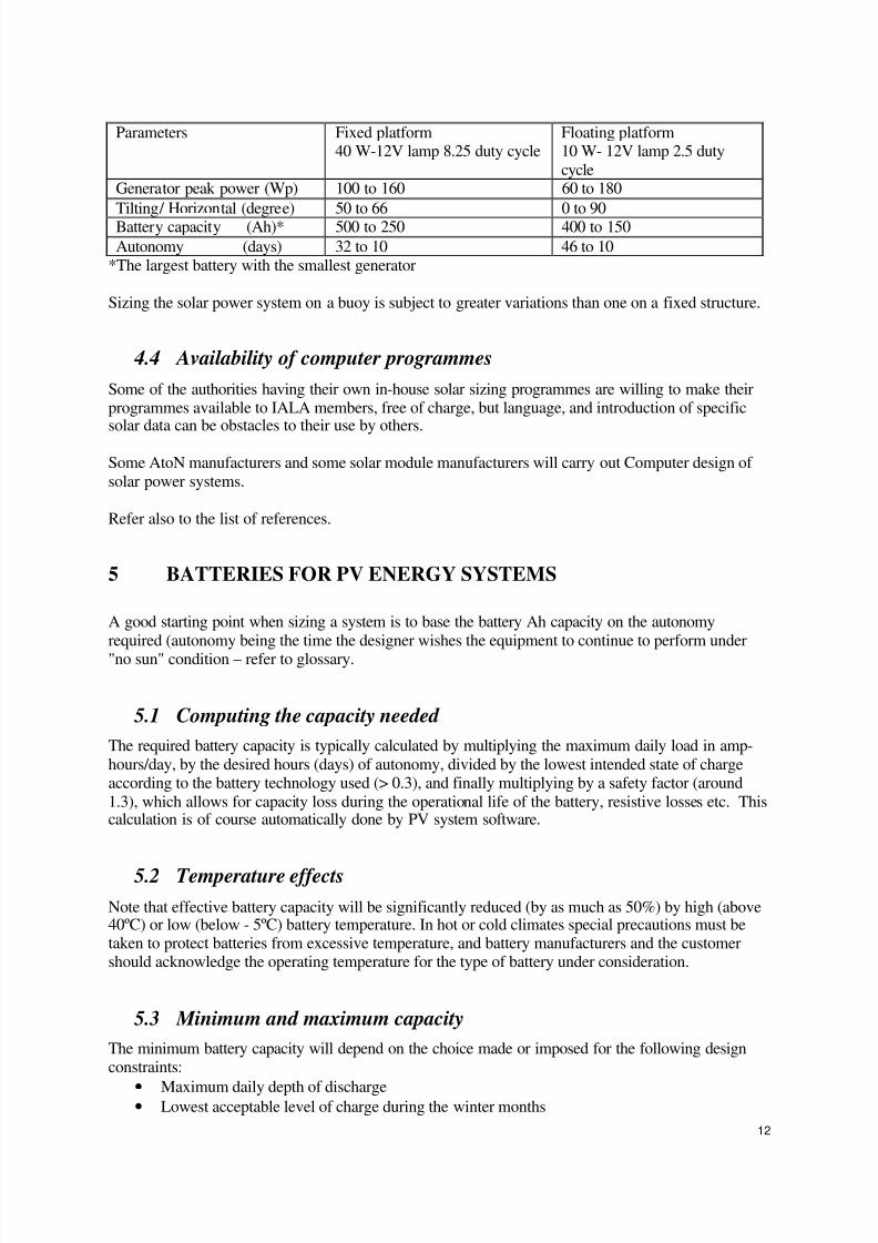
Parameters Fixed platform
40 W-12V lamp 8.25 duty cycle
Floating platform
10 W- 12V lamp 2.5 dutycycleGenerator peak power (Wp) 100 to 160 60 to 180Tilting/ Horizontal (degree) 50 to 66 0 to 90Battery capacity (Ah)* 500 to 250 400 to 150Autonomy (days) 32 to 10 46 to 10
*The largest battery with the smallest generator
Sizing the solar power system on a buoy is subject to greater variations than one on a fixed structure.
4.4 Availability of computer programmes
Some of the authorities having their own in-house solar sizing programmes are willing to make theirprogrammes available to IALA members, free of charge, but language, and introduction of specificsolar data can be obstacles to their use by others.
Some AtoN manufacturers and some solar module manufacturers will carry out Computer design of solar power systems.
Refer also to the list of references.
5 BATTERIES FOR PV ENERGY SYSTEMS
8/3/2019 Gui Del 22
http://slidepdf.com/reader/full/gui-del-22 13/26
• Allowance for “no sun“ days (from meteorological or insolation data). According to theinquiry, 20 days minimum seems a good figure for medium latitude (less in lower latitudes
and more in higher ones).• Ease of access to the AtoN.• Ability of the battery to accept the peak output of the generator without overcharging, mainly
for sealed batteries (a situation that may arise with a self -regulating system).
It should be noted that:• The maximum battery capacity will usually be determined by consideration of cost, available
space, weight, and handling capacity. As a general rule the number of batteries in parallel
should be kept to a minimum. (Five is a typical figure for good quality batteries coming fromthe same production batch, installed at the same time and working under the same regime of charge and discharge. It could vary according to the quality of the battery). Somemanufacturers offer individual cells or blocks of 2 or 3 cells, with high Ah capacity, and it isusually better to use these in series rather than to parallel smaller batteries.
• Use of lead-acid batteries may require an increase in battery capacity to prevent deepdischarge during winter months, but in this situation the effect of low temperature on thebattery should be taken into account. For these reasons nickel-cadmium batteries are oftenpreferred for the worst cases (very high latitude and very low temperature).
• Batteries with low self –discharge become important when the design requires a longautonomous period for the system.
5.4 Batteries on buoys
The expected battery life on buoys can be shorter than for a land station, due to shock-load damage of the plates especially for flooded batteries.

8/3/2019 Gui Del 22
http://slidepdf.com/reader/full/gui-del-22 14/26
5.5.2 Valve Regulated Lead Acid (VRLA) Battery
5.5.2.1 Absorbed Glass Matt (AGM)Not recommended for buoys because the attitude of the battery affects its performance. However,these batteries are particularly suitable for fixed aids because they are easy to handle.
Advantages:• No requirement for topping up• Minimal maintenance required• Recyclable• Safer than flooded lead acid batteries to transport and handle
Disadvantages:• Shorter Life compared to flooded lead acid - typically 5 – 8 years• Controlled charging required.• Limited temperature operation - Reduced life at high temperature• Difficult to check capacity remaining.
5.5.2.2 Gel Electrolyte
Similar to AGM cells but can be used on buoys, as attitude does not affect performance. The life of these cells are slightly less than AGM cells
5.5.3 Nickel Cadmium
These batteries are preferred for long term use in high and low temperature (will not freeze) and wheredeep discharge is expected
8/3/2019 Gui Del 22
http://slidepdf.com/reader/full/gui-del-22 15/26
a decision will be influenced by the costs of accessing the AtoN site, and by the ease of fast access inthe event of a failure.
5.8 Battery maintenance
Refer to the separate IALA Guideline on batteries, but note that ventilation is required when all typesof secondary batteries are being charged.
Even very small solar installations can overcharge a battery given a suitable combination of circumstances. Sealed batteries of all types have some form of a pressure vent and if overcharge they will
generate hydrogen in potentially explosive proportions. All battery housings, including buoys, must beeffectively ventilated and free from ignition sources.
Safe working practices must be established for opening battery boxes or compartments.
5.9 Charge regulation
A high charge efficiency is needed so that most of the energy produced by the PV array is stored in thebattery. A modern electronic charge regulator will generally ensure this.
There are three possibilities for the charge regime:
5.9.1 No charge regulator and conventional PV module.
• Mainly for low latitude and nickel-cadmium batteries• A lack of a regulator can mean periodical overcharge and gassing of the battery,
8/3/2019 Gui Del 22
http://slidepdf.com/reader/full/gui-del-22 16/26
• Generally charge regulators have a long Mean Time Between Failures [MTBF]. Staticswitching (e.g. MOS FET) charge regulators have a very high level of reliability with
very low voltage drop.
5.10 Charging parameters
For long battery life, the maximum charge voltage should be set to ensure the battery is fully chargedfor a significant period of time during summer. This adjustment represents a delicate balance betweenexcessive water consumption and the battery never becoming fully charged.
For a vented battery, some water consumption, apart from evaporation, between the specified toppingup levels over a year's operation can be considered normal.
For a “sealed” battery overcharging can mean a loss of capacity. Battery manufacturers’recommendations should be accurately followed on this point.
The use of a low voltage load disconnect mechanism, or load shedding, is also recommended toprevent premature ageing of the battery and possible failure, which may result from excessive battery
discharge. This feature may be included in the load; for example this feature is included in someAtoN lanterns, so that it can be a part of a simple non-regulated, or self-regulated, solar power system.Electronic charge regulators are also available with this feature.
As many charge regulators are based on the measurement of battery voltage it is very important thatthe voltage measured by the regulator is not concerned with a voltage drop (loss) due to conductor sizeor poor connections (locking, corrosion). Some charge regulators, especially for larger solar systems,are provided with separate terminals for battery voltage sensing, and require that separate cable coresbe run to the battery for this purpose.

8/3/2019 Gui Del 22
http://slidepdf.com/reader/full/gui-del-22 17/26
necessary. Sometimes the remedial action may be initiated remotely over the monitoring and controllink.
Some regulators are available with a data port output; this is useful for allowing easy connection to aremote monitoring system. Such regulators can provide battery voltage and condition data via the dataport.
5.12 Blocking diodes
A blocking diode is used to prevent undesired discharge current from battery to module(s) or through a
shunt regulator.
The blocking diode should be of the low voltage loss type, such as a Schottky diode. It is advisable touse one blocking diode per module because only one module would then be affected by a diodefailure.
When one blocking diode is used for several modules, a shaded or short-circuited module can becomea load for the others. The switching device in a series regulator can save the blocking diode and corre-
sponding energy loss, but in the case of a failure of the switching device, the battery can partiallydischarge through the PV module. With a shunt regulator, a blocking diode is essential.
A blocking diode should have a minimum direct current value of three times the short circuit currentof the module (array) on which it is installed.
6 PRACTICAL CONSIDERATIONS

8/3/2019 Gui Del 22
http://slidepdf.com/reader/full/gui-del-22 18/26
to ensure that no excessive mechanical load is placed on the lead at the point where it enters themodule. Low WG number (Low Wire Gauge number=high square mm) should be used to havereduced resistance and a sufficient mechanical strength.
6.1.2 Fixing
Care should be taken at installation to see that the mounting hardware does not stress the modulePrevention against galvanic corrosion between dissimilar metals (frame/structure) using insulators orstand-offs is recommended.Care should be taken with total or partial shadowing of the modules during the day or any season.Attention should be paid to growing trees, grass, and other equipment.Note that shadowing of one cell in a module will cause the output from all the cells in that series stringto be partially or totally lost.Devices (special screws or nuts, welded pieces, etc) to dissuade thieves from removing the modulesare recommended as well as a notice board indicating the importance of the installation for maritimesafety.In areas where theft is a problem, lanterns with integral solar power systems may be desirable.Remote monitoring is useful to detect intrusion.
6.1.3 Protection from bird fouling
In some areas birds cause real problems by fouling modules. A great number of devices have beendevised but the results of the survey in 2000 show that none is totally effective, and bird spikes (plasticor metal) are preferred. Devices working at some places don’t work at others. Vertical modules reducethe problem, but imply over sizing. The hazards presented to servicing personnel by metal bird spikesmust be considered.
6.1.4 Mechanical protection
Protection to reduce the effect of wave impact, storms, vandalism, theft, and buoy-handling, is
8/3/2019 Gui Del 22
http://slidepdf.com/reader/full/gui-del-22 19/26
6.2 Lightning protection
It can be said that no protection is better than a bad protection system.
A protected station should have its lightning protection system checked every year.A current practice is to ground (earth) the metallic frames of all equipment - electric conductors areleft floating.On non-metal buoys, an air terminal on the top, directly connected to the mooring chain, can limitdamage from lightning.If the voltage of the PV generator is above 50 V, it is suggested practice to ground one conductor(generally the negative one).Refer to the IALA Guideline.
7 MAINTENANCE
Maintenance of a PV power system at an AtoN should, of course, be planned as part of a totalmaintenance programme for all components of the AtoN site.
7.1 Programmed maintenance
For the PV power system, maintenance will probably include some or all of the following.• Battery top-up as necessary.• Check state of charge, open-circuit voltage and loaded voltage, and specific gravity and the
general condition of the battery. [Measuring of specific gravity applies to flooded Lead Acidbatteries only]
• Check external aspect of the battery plates and accumulation of sediment when batteries with
8/3/2019 Gui Del 22
http://slidepdf.com/reader/full/gui-del-22 20/26
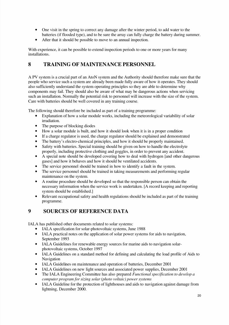
• One visit in the spring to correct any damage after the winter period, to add water to thebatteries (if flooded type), and to be sure the array can fully charge the battery during summer.
•
After that it should be possible to move to an annual inspection.With experience, it can be possible to extend inspection periods to one or more years for manyinstallations.
8 TRAINING OF MAINTENANCE PERSONNEL
A PV system is a crucial part of an AtoN system and the Authority should therefore make sure that the
people who service such a system are already been made fully aware of how it operates. They shouldalso sufficiently understand the system operating principles so they are able to determine whycomponents may fail. They should also be aware of what may be dangerous actions when servicingsuch an installation. Normally the potential risk to personnel will increase with the size of the system.Care with batteries should be well covered in any training course.
The following should therefore be included as part of a training programme:• Explanation of how a solar module works, including the meteorological variability of solar
irradiation.• The purpose of blocking diodes• How a solar module is built, and how it should look when it is in a proper condition• If a charge regulator is used, the charge regulator should be explained and demonstrated• The battery’s electro-chemical principles, and how it should be properly maintained.• Safety with batteries. Special training should be given on how to handle the electrolyte
properly, including protective clothing and goggles, in order to prevent any accident.• A special note should be developed covering how to deal with hydrogen [and other dangerous

8/3/2019 Gui Del 22
http://slidepdf.com/reader/full/gui-del-22 21/26
10 SOLAR PHOTOVOLTAIC GLOSSARY
Note that the terms relating to the solar photovoltaic part of the system are extracted from IEC TC 82“Solar photovoltaic energy systems Guide: Glossary of terms and symbols used in solar photovoltaicenergy systems - part I - 82/154”.
Attention is drawn to the IALA Dictionary, chapter 6, power Supplies for stations. Section 2, NaturalEnergy Sources and Low Level Sources. Also Section 4 Electrochemical cells and batteries.
Array:
A mechanically integrated assembly of modules or panels together with support structure butexclusive of foundation, tracking, thermal control and other such components, to form a DC powerproducing unit.
Autonomy of a battery:The autonomy of a battery is a theoretical concept. It indicates the time in days (or hours) a batterywill take to discharge from a fully charged state [100 % state of charge (SOC)] to a chosen cut-off level state of charge, powering the AtoN system without any energy coming from the generator.
The cut-off level is chosen by the designer according to the battery technology used.It must be noted that the electrical power consumed by the AtoN system (in Ah/day or Wh/day) mayvary with weather conditions and/or season of the year. It is recommended to use the worst conditions(night duration & temperature) to calculate the battery autonomy.
8/3/2019 Gui Del 22
http://slidepdf.com/reader/full/gui-del-22 22/26
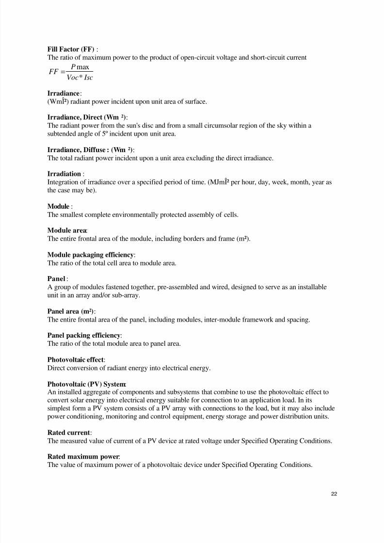
Fill Factor (FF) : The ratio of maximum power to the product of open-circuit voltage and short-circuit current
IscVocPFF
*max=
Irradiance:(Wmβ) radiant power incident upon unit area of surface.
Irradiance, Direct (Wm ²):The radiant power from the sun's disc and from a small circumsolar region of the sky within a
subtended angle of 5º incident upon unit area.Irradiance, Diffuse : (Wm ²):The total radiant power incident upon a unit area excluding the direct irradiance.
Irradiation :Integration of irradiance over a specified period of time. (MJmβ per hour, day, week, month, year asthe case may be).
Module :The smallest complete environmentally protected assembly of cells.
Module area:The entire frontal area of the module, including borders and frame (m²).
Module packaging efficiency:The ratio of the total cell area to module area.

8/3/2019 Gui Del 22
http://slidepdf.com/reader/full/gui-del-22 23/26
Rated power:The value of power output of a photovoltaic device at rated voltage under Specified OperatingConditions.
Rated voltage :The voltage at which a PV device is designed to produce near maximum electrical power underSpecified Operating Conditions.
Reference solar cell:A solar cell used to measure irradiance or to set simulator irradiance levels in terms of a referencesolar spectral irradiance distribution.
Short circuit current (Isc): The output current of a photovoltaic device in the short-circuit condition at a particular temperatureand irradiance.
Solar cell:The basic photovoltaic device that generates electricity when exposed to sunlight.
Solar cell area:The entire frontal area of the solar cell, including the cell grid (cm²).
Spectral response (absolute) (S abs):The short circuit current density generated by unit irradiance at a particular wavelength (AWι),plotted as a function of wavelength.
Spectral response (relative) (S rel):

8/3/2019 Gui Del 22
http://slidepdf.com/reader/full/gui-del-22 24/26
11.2 Summary of main conclusions
As a result of an analysis of the returned questionnaires, it appears that in 2000, for the AtoN operated
by the respondents to the survey:• 49% of fixed aids and 30.6% of floating aids were powered by solar PV systems.• 12.6% of fixed aids were powered from the public utilities supply.• 3.3% of fixed aids and 8.2% of floating aids were powered by primary cells (not rechargeable)
mainly in the countries operating floating AtoN above 60' latitude.• 1.2% of fixed aids and 2.3% of floating aids were powered by gas (mainly acetylene).• 1.2% of fixed aids were powered by diesel generators.• 0.1% of fixed aids were powered by kerosene.• 0.3% of fixed aids and none of the floating aids were powered by wind-powered generator.• Only a tiny number of AtoN utilised wave, seawater battery or other unusual power sources.• Very few fixed AtoN had hybrid sources. These were mainly solar PV with diesel generator
back-up and very occasionally also with wind back-up. Some were PV with wind back-up.• A small number (less than I %) of floating AtoN had hybrid sources mainly PV and wave, or
PV and primary cells.
11.3 Tabular summary - load
Analysis of the survey information showed that the averaged load values were as follows.
Fixed FloatingParametersMin Typical Max Min Typical Max
Average power of the load (Watt) 3 21 50 3 10 22Max. power of the load (Watt) 5 181 1000 5 25 100Min. power of the load (Watt) 1.5 7 20 2 7 10
8/3/2019 Gui Del 22
http://slidepdf.com/reader/full/gui-del-22 25/26
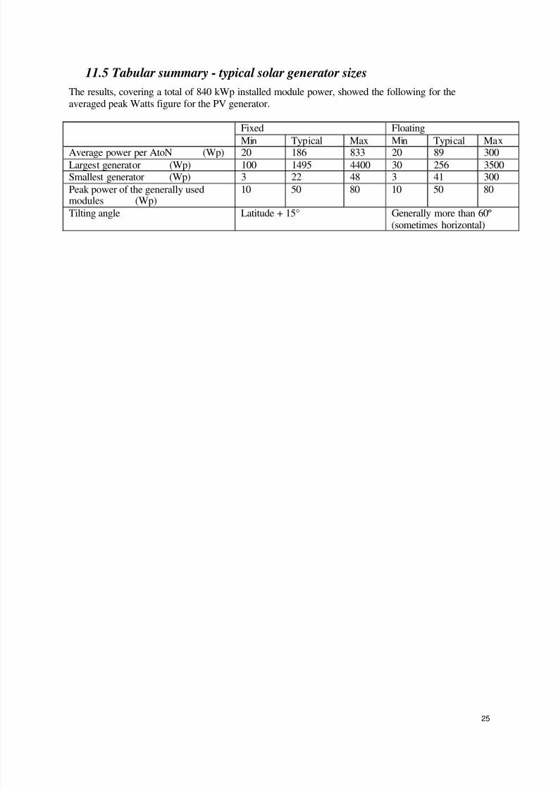
11.5 Tabular summary - typical solar generator sizes
The results, covering a total of 840 kWp installed module power, showed the following for the
averaged peak Watts figure for the PV generator.
Fixed FloatingMin Typical Max Min Typical Max
Average power per AtoN (Wp) 20 186 833 20 89 300Largest generator (Wp) 100 1495 4400 30 256 3500Smallest generator (Wp) 3 22 48 3 41 300Peak power of the generally used
modules (Wp)
10 50 80 10 50 80
Tilting angle Latitude + 15° Generally more than 60º(sometimes horizontal)

8/3/2019 Gui Del 22
http://slidepdf.com/reader/full/gui-del-22 26/26
26