FR S FR -S 520-0.1K to 3.7K (-R)(-C ) FR -S 520-0.1K to 3 ...
181
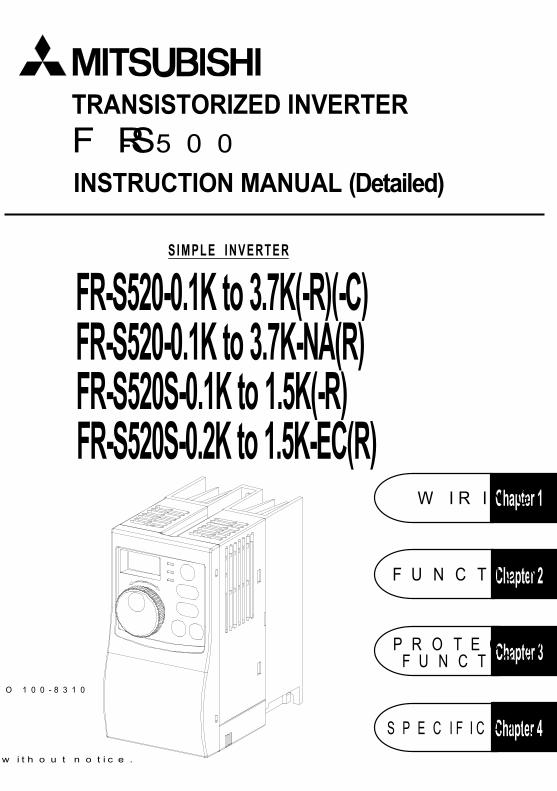
FR -S500 T R A N S I S T O R I Z E D I N V E R T E R I N S T R U C T I O N M A N U A L ( D e t a i l e d ) F R - S 5 2 0 - 0 . 1 K t o 3 . 7 K - N A ( R ) F R - S 5 2 0 S - 0 . 1 K t o 1 . 5 K ( - R ) F R - S 5 2 0 S - 0 . 2 K t o 1 . 5 K - E C ( R ) S I M P L E I N V E R T E R C h a p t e r 3 C h a p t e r 2 C h a p t e r 4 FU N C TIO N S C h a p t e r 1 W IR IN G FU N C TIO N S S P E C IFIC A TIO N P R O TE C TIV E F R - S 5 2 0 - 0 . 1 K t o 3 . 7 K ( - R ) ( - C ) w ith o u t n o tic e . O 100-8310
Transcript of FR S FR -S 520-0.1K to 3.7K (-R)(-C ) FR -S 520-0.1K to 3 ...
F R - S 5 0 0
T R A N S I S T O R I Z E D I N V E R T E R
I N S T R U C T I O N M A N U A L ( D e t a i l e d )
FR
-S500
INSTRUCTION MANUAL (Detailed)TRANSISTORIZED INVERTER
F R - S 5 2 0 - 0 . 1 K t o 3 . 7 K - N A ( R )F R - S 5 2 0 S - 0 . 1 K t o 1 . 5 K ( - R )F R - S 5 2 0 S - 0 . 2 K t o 1 . 5 K - E C ( R )
S I M P L E I N V E R T E R
C h a p t e r 3
C h a p t e r 2
C h a p t e r 4
F U N C T I O N S
C h a p t e r 1W I R I N G
F U N C T I O N S
S P E C I F I C A T I O N S
P R O T E C T I V E
F R - S 5 2 0 - 0 . 1 K t o 3 . 7 K ( - R ) ( - C )
S p e c i f i c a t i o n s s u b j e c t t o c h a n g e w i t h o u t n o t i c e .
H E A D O F F I C E : M I T S U B I S H I D E N K I B L D G M A R U N O U C H I T O K Y O 1 0 0 - 8 3 1 0
P r i n t e d i n J a p a nI B ( N A ) - 0 6 0 0 0 2 7 - A ( 0 0 0 3 ) M E E
A-1
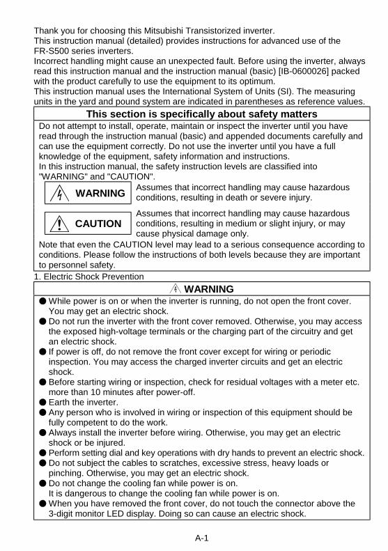
Thank you for choosing this Mitsubishi Transistorized inverter.This instruction manual (detailed) provides instructions for advanced use of theFR-S500 series inverters.Incorrect handling might cause an unexpected fault. Before using the inverter, alwaysread this instruction manual and the instruction manual (basic) [IB-0600026] packedwith the product carefully to use the equipment to its optimum.This instruction manual uses the International System of Units (SI). The measuringunits in the yard and pound system are indicated in parentheses as reference values.
This section is specifically about safety mattersDo not attempt to install, operate, maintain or inspect the inverter until you haveread through the instruction manual (basic) and appended documents carefully andcan use the equipment correctly. Do not use the inverter until you have a fullknowledge of the equipment, safety information and instructions.In this instruction manual, the safety instruction levels are classified into"WARNING" and "CAUTION".
WARNINGAssumes that incorrect handling may cause hazardousconditions, resulting in death or severe injury.
CAUTIONAssumes that incorrect handling may cause hazardousconditions, resulting in medium or slight injury, or maycause physical damage only.
Note that even the CAUTION level may lead to a serious consequence according toconditions. Please follow the instructions of both levels because they are importantto personnel safety.
1. Electric Shock Prevention
WARNINGWhile power is on or when the inverter is running, do not open the front cover.You may get an electric shock.Do not run the inverter with the front cover removed. Otherwise, you may accessthe exposed high-voltage terminals or the charging part of the circuitry and getan electric shock.If power is off, do not remove the front cover except for wiring or periodicinspection. You may access the charged inverter circuits and get an electricshock.Before starting wiring or inspection, check for residual voltages with a meter etc.more than 10 minutes after power-off.Earth the inverter.Any person who is involved in wiring or inspection of this equipment should befully competent to do the work.Always install the inverter before wiring. Otherwise, you may get an electricshock or be injured.Perform setting dial and key operations with dry hands to prevent an electric shock.Do not subject the cables to scratches, excessive stress, heavy loads orpinching. Otherwise, you may get an electric shock.Do not change the cooling fan while power is on.It is dangerous to change the cooling fan while power is on.When you have removed the front cover, do not touch the connector above the3-digit monitor LED display. Doing so can cause an electric shock.
A-2
2. Fire Prevention
CAUTIONMount the inverter to incombustible material. Mounting it to or near combustiblematerial can cause a fire.If the inverter has become faulty, switch off the inverter power. A continuous flowof large current could cause a fire.Do not connect a resistor directly to the DC terminals P(+), N(−). This couldcause a fire.
3. Injury Prevention
CAUTIONApply only the voltage specified in the instruction manual to each terminal toprevent damage etc.Ensure that the cables are connected to the correct terminals. Otherwise,damage etc. may occur.Always make sure that polarity is correct to prevent damage etc.While power is on and for some time after power-off, do not touch the inverter orbrake resistor as they are hot and you may get burnt.
4. Additional instructionsAlso note the following points to prevent an accidental failure, injury, electric shock, etc.(1) Transportation and installation
CAUTIONWhen carrying products, use correct lifting gear to prevent injury.Do not stack the inverter boxes higher than the number recommended.Ensure that installation position and material can withstand the weight of theinverter. Install according to the information in the Instruction Manual.Do not operate if the inverter is damaged or has parts missing.When carrying the inverter, do not hold it by the front cover or setting dial; it may fall offor fail.Do not stand or rest heavy objects on the inverter.Check the inverter mounting orientation is correct.Prevent screws, wire fragments, other conductive bodies, oil or other flammablesubstances from entering the inverter.Do not drop the inverter, or subject it to impact.Use the inverter under the following environmental conditions:
Ambienttemperature
-10°C to +50°C (14°F to 122°F) (non-freezing)
Ambient humidity 90%RH or less (non-condensing)Storagetemperature
-20°C to +65°C * (-4°F to 149°F)
AmbienceIndoors (free from corrosive gas, flammable gas,oil mist, dust and dirt)
En
viro
nm
en
t
Altitude, vibration
Maximum 1000m (3280.80feet) above sea level forstandard operation. After that derate by 3% forevery extra 500m (1640.40feet) up to 2500m(8202.00feet) (91%).5.9m/s2 or less (conforming to JIS C0911)
*Temperatures applicable for a short time, e.g. in transit.
A-3
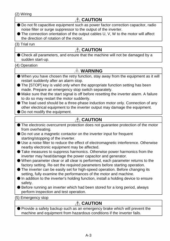
(2) Wiring
CAUTIONDo not fit capacitive equipment such as power factor correction capacitor, radionoise filter or surge suppressor to the output of the inverter.The connection orientation of the output cables U, V, W to the motor will affectthe direction of rotation of the motor.
(3) Trial run
CAUTIONCheck all parameters, and ensure that the machine will not be damaged by asudden start-up.
(4) Operation
WARNINGWhen you have chosen the retry function, stay away from the equipment as it willrestart suddenly after an alarm stop.The [STOP] key is valid only when the appropriate function setting has beenmade. Prepare an emergency stop switch separately.Make sure that the start signal is off before resetting the inverter alarm. A failureto do so may restart the motor suddenly.The load used should be a three-phase induction motor only. Connection of anyother electrical equipment to the inverter output may damage the equipment.Do not modify the equipment.
CAUTIONThe electronic overcurrent protection does not guarantee protection of the motorfrom overheating.Do not use a magnetic contactor on the inverter input for frequentstarting/stopping of the inverter.Use a noise filter to reduce the effect of electromagnetic interference. Otherwisenearby electronic equipment may be affected.Take measures to suppress harmonics. Otherwise power harmonics from theinverter may heat/damage the power capacitor and generator.When parameter clear or all clear is performed, each parameter returns to thefactory setting. Re-set the required parameters before starting operation.The inverter can be easily set for high-speed operation. Before changing itssetting, fully examine the performances of the motor and machine.In addition to the inverter's holding function, install a holding device to ensuresafety.Before running an inverter which had been stored for a long period, alwaysperform inspection and test operation.
(5) Emergency stop
CAUTIONProvide a safety backup such as an emergency brake which will prevent themachine and equipment from hazardous conditions if the inverter fails.
A-4
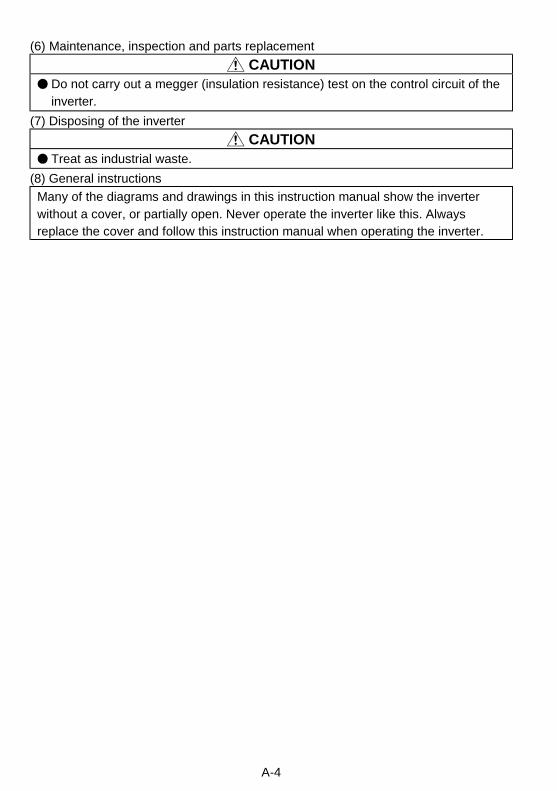
(6) Maintenance, inspection and parts replacement
CAUTIONDo not carry out a megger (insulation resistance) test on the control circuit of theinverter.
(7) Disposing of the inverter
CAUTIONTreat as industrial waste.
(8) General instructions
Many of the diagrams and drawings in this instruction manual show the inverterwithout a cover, or partially open. Never operate the inverter like this. Alwaysreplace the cover and follow this instruction manual when operating the inverter.
I
CONTENTS1. WIRING 1
1.1 Japanese Version .................................................................................... 21.1.1 Terminal connection diagram .....................................................................21.1.2 Layout and wiring of main circuit terminals................................................3
1.2 North America Version............................................................................. 41.2.1 Terminal connection diagram .....................................................................41.2.2 Layout and wiring of main circuit terminals................................................5
1.3 European Version .................................................................................... 61.3.1 Terminal connection diagram .....................................................................61.3.2 Layout and wiring of main circuit terminals................................................7
1.4 Description of I/O Terminal Specifications .............................................. 81.4.1 Main circuit ...................................................................................................81.4.2 Control circuit ...............................................................................................8
1.5 How to Use the Main Circuit Terminals ................................................. 101.5.1 Cables, wiring lengths, crimping terminals, etc. ......................................101.5.2 Wiring instructions .....................................................................................111.5.3 Peripheral devices.....................................................................................121.5.4 Leakage current and installation of earth leakage circuit breaker.......131.5.5 Power-off and magnetic contactor (MC)..................................................151.5.6 Regarding the installation of the power factor improving reactor ........161.5.7 Regarding noise and the installation of a noise filter ..............................161.5.8 Grounding precautions..............................................................................171.5.9 Regarding power harmonics and Japanese power harmonic
suppression guideline ................................................................................181.6 How to Use the Control Circuit Terminals ............................................. 19
1.6.1 Terminal block layout ................................................................................191.6.2 Cables, wiring lengths, crimping terminals, etc. ......................................191.6.3 Wiring instructions .....................................................................................201.6.4 Changing the control logic ........................................................................20
1.7 Input Terminals ...................................................................................... 231.7.1 Run (start) and stop (STF, STR, STOP)..................................................231.7.2 Connection of frequency setting potentiometer and output frequency
meter (10, 2, 5, 4, AU)...............................................................................261.7.3 External frequency selection (REX, RH, RM, RL) ..................................271.7.4 Indicator connection and adjustment .......................................................291.7.5 Control circuit common terminals (SD, 5, SE).........................................321.7.6 Signal inputs by contactless switches......................................................32
1.8 How to Use the Input Signals(Assigned Terminals RL, RM, RH, STR)............................................... 33
1.8.1 Multi-speed setting (RL, RM, RH, REX signals): Setting "0, 1, 2, 8"Remote setting (RL, RM, RH signals): Setting "0, 1, 2" .........................33
Co
nte
nts
II
1.8.2 Second function selection (RT signal): Setting "3"..................................331.8.3 Current input selection "AU signal": Setting "4".......................................331.8.4 Start self-holding selection (STOP signal): Setting "5" ...........................331.8.5 Output shut-off (MRS signal): Setting "6" ................................................341.8.6 External thermal relay input: Setting "7" ..................................................341.8.7 Jog operation (JOG signal): Setting "9" ...................................................351.8.8 Reset signal: Setting "10" .........................................................................351.8.9 PID control valid terminal: Setting "14" ....................................................361.8.10 PU operation/external operation switching: Setting "16"......................36
1.9 Handling of the RS-485 Connector(Type with RS-485 Communication Function)....................................... 36
1.10 Design Information............................................................................... 39
2. FUNCTIONS 402.1 Function (Parameter) List ...................................................................... 412.2 List of Parameters Classified by Purpose of Use .................................. 512.3 Explanation of Functions (Parameters) ................................................. 53
2.3.1 Torque boost ...........................................................................532.3.2 Maximum and minimum frequency ........................................542.3.3 Base frequency, Base frequency voltage .....................542.3.4 Multi-speed operation to to .......562.3.5 Acceleration/deceleration time ....................572.3.6 Electronic overcurrent protection ....................................................592.3.7 DC injection brake ..........................................................592.3.8 Starting frequency ............................................................................602.3.9 Load pattern selection ......................................................................612.3.10 Jog frequency ........................................................................62
2.3.11 RUN key rotation direction selection ............................................622.3.12 Stall prevention function and current limit function ......................632.3.13 Stall prevention .............................................................642.3.14 Acceleration/deceleration pattern .................................................662.3.15 Extended function display selection ..............................................672.3.16 Frequency jump to ................................................................672.3.17 Speed display .................................................................................682.3.18 Biases and gains of the frequency setting voltage (current)
to ..........................................................................692.3.19 Start-time ground fault detection selection ...................................73
2.4 Output Terminal Function Parameters .................................................. 732.4.1 Up-to-frequency sensitivity ...............................................................732.4.2 Output frequency detection ....................................................74
2.5 Current Detection Function Parameters................................................ 752.5.1 Output current detection functions .........................................752.5.2 Zero current detection .............................................................76
2.6 Display Function Parameters ................................................................ 77
III
2.6.1 Monitor display ........................................................................772.6.2 Setting dial function selection ..........................................................782.6.3 Monitoring reference ...............................................................79
2.7 Restart Operation Parameters............................................................... 792.7.1 Restart setting .........................................................................79
2.8 Additional Function Parameters ............................................................ 812.8.1 Remote setting function selection ...................................................81
2.9 Terminal Function Selection Parameters .............................................. 832.9.1 Input terminal function selection ...........................832.9.2 Output terminal function selection ..........................................85
2.10 Operation Selection Function Parameters .......................................... 862.10.1 Retry function ......................................................862.10.2 PWM carrier frequency .........................................................872.10.3 Applied motor .................................................................................882.10.4 Voltage input selection ...................................................................882.10.5 Input filter time constant .................................................................892.10.6 Reset selection/PU stop selection ................................................892.10.7 Cooling fan operation selection .....................................................912.10.8 Parameter write inhibit selection ...................................................922.10.9 Reverse rotation prevention selection ..........................................932.10.10 Operation mode selection ...........................................................932.10.11 PID control to .......................................................................96
2.11 Auxiliary Function Parameters........................................................... 1042.11.1 Slip compensation ..................................................... 1042.11.2 Automatic torque boost selection ............................................... 1042.11.3 Motor primary resistance ............................................................ 105
2.12 Calibration Parameters...................................................................... 1062.12.1 Meter (frequency meter) calibration (Japanese version).......... 1062.12.2 Meter (frequency meter) calibration (NA and EC version)....... 108
2.13 Clear Parameters .............................................................................. 1102.13.1 Parameter clear ........................................................................... 1102.13.2 Alarm history clear ...................................................................... 110
2.14 Communication Parameters(Only for the type having the RS-485 communication function) .......... 111
2.14.1 Communication settings to , ...................................... 1132.14.2 Operation and speed command write .............................. 1242.14.3 Link start mode selection ............................................................ 1252.14.4 E2PROM write selection ............................................................. 126
2.15 Parameter Unit (FR-PU04) Setting.................................................... 1272.15.1 Parameter unit display language switching ............................... 1272.15.2 Buzzer sound control .................................................................. 1272.15.3 PU contrast adjustment .............................................................. 1282.15.4 PU main display screen data selection ...................................... 128
Co
nte
nts
IV
2.15.5 PU disconnection detection/PU setting lock .............................. 129
3. PROTECTIVE FUNCTIONS 1303.1 Errors (Alarms) .................................................................................... 131
3.1.1 Error (alarm) definitions.......................................................................... 1313.1.2 To know the operating status at the occurrence of alarm
(Only when FR-PU04 is used) .............................................................. 1393.1.3 Correspondence between digital and actual characters ..................... 1393.1.4 Resetting the inverter ............................................................................. 139
3.2 Troubleshooting ................................................................................... 1403.2.1 Motor remains stopped .......................................................................... 1403.2.2 Motor rotates in opposite direction ........................................................ 1413.2.3 Speed greatly differs from the setting ................................................... 1413.2.4 Acceleration/deceleration is not smooth............................................... 1413.2.5 Motor current is large ............................................................................. 1413.2.6 Speed does not increase....................................................................... 1413.2.7 Speed varies during operation............................................................... 1423.2.8 Operation mode is not changed properly ............................................. 1423.2.9 Operation panel display is not operating .............................................. 1423.2.10 Parameter write cannot be performed................................................ 142
3.3 Precautions for Maintenance and Inspection ...................................... 1433.3.1 Precautions for maintenance and inspection ....................................... 1433.3.2 Check items ............................................................................................ 1433.3.3 Periodic inspection ................................................................................. 1433.3.4 Insulation resistance test using megger ............................................... 1443.3.5 Pressure test........................................................................................... 1443.3.6 Daily and periodic inspection................................................................. 1443.3.7 Replacement of parts............................................................................. 1483.3.8 Measurement of main circuit voltages, currents and powers.............. 151
4. SPECIFICATIONS 1544.1 Specification List.................................................................................. 155
4.1.1 Ratings .................................................................................................... 1554.1.2 Common specifications.......................................................................... 157
4.2 Outline Drawings ................................................................................. 159
5. INSTRUCTIONS 1615.1 Selecting Instructions........................................................................... 1625.2 Peripheral Selecting Instructions ......................................................... 1625.3 Operating Instructions ......................................................................... 164
APPENDIX 166APPENDIX 1 PARAMETER DATA CODE LIST ....................................... 167
1
1
This chapter explains the basic "wiring" for use of thisproduct. Always read the instructions before use.For description of "installation", refer to the instructionmanual (basic).
1.1 Japanese Version ......................................................21.2 North America Version...............................................41.3 European Version ......................................................61.4 Description of I/O Terminal specification....................81.5 How to Use the Main Circuit Terminals ....................101.6 How to Use the Control Circuit Terminals ................191.7 Input Terminals ........................................................231.8 How to Use the Input Signals
(Assigned Terminals RL, RM, RH, STR) ..................331.9 Handling of the RS-485 Connector
(Type with RS-485 Communication Function) ..........361.10 Design Information.................................................39
<Abbreviations>PUControl panel and parameter unit (FR-PU04)InverterMitsubishi transistorized inverter FR-S500 seriesFR-S500Mitsubishi transistorized inverter FR-S500 seriesPr.Parameter number
1. WIRING
Chapter 1
Chapter 2
Chapter 3
Chapter 4
2
1.1 Japanese Version
1.1.1 Terminal connection diagramFR-S520-0.1K to 3.7K (-R) (-C)
Power factor improving DC reactor(FR-BEL: Option)
PCExternal transistor common
24VDC power supplyContact input common (source)
STF
STR
RH
RM
RL
SD
Forward rotation start
Reverse rotation start
Middle
High
Low
Frequency setting signals (Analog)
10 (+5V)
22
3
1
4 to 20mADC (+) 4 (4 to 20mADC)
Frequencysettingpotentiometer1/2W1k(*4)
RUN
SE
Running
FM
SD
Control input signals(No voltage input allowed)
Jumper: Remove this jumper when FR-BEL is connected.
Motor
IM
Ground
Alarmoutput
A
B
C
UVW
P1
P
N
(+) (-)
Earth (Ground)
Selected
Multi-speed selection
Operation status outputContact input common
5 (Common)
Open collectoroutput common
Current input (-)
3-phase ACpower supply
NFBRST
MC
Opencollectoroutputs
Calibration resistor (*2)
SINK
SOURCE
RS-485 Connector (*1)
Inverter
Main circuit terminal Control circuit input terminal Control circuit output terminal
DC 0 to 5VDC 0 to 10V
Indicator1mA full-scaleAnalog meter(Digital indicator)
1mA
(*3)
When using current input with asthe frequency setting signal, set "4" in any of Pr. 60 to Pr. 63 (input terminal function selection) and assign AU (current input selection) to any of terminals RH, RM, RL and STR.
(Note)
Be careful not to shortterminals PC-SD.
REMARKS*1 Only the type with RS-485 communication function.*2 Not needed when the setting dial is used for calibration. This resistor is used
when calibration must be made near the frequency meter for such a reason as aremote frequency meter. Note that the needle of the frequency meter may notdeflect to full-scale when the calibration resistor is connected. In this case, useboth the resistor and setting dial for calibration.
*3 You can switch between the sink and source logic positions. Refer to page 20.*4 When the setting potentiometer is used frequently, use a 2W1kΩ potentiometer.
CAUTIONKeep the signal lines more than 10cm (3.94inches) away from the power line.
3
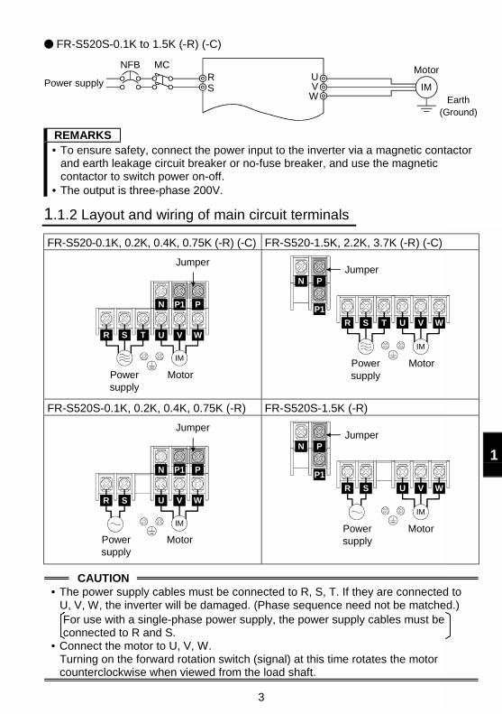
1
FR-S520S-0.1K to 1.5K (-R) (-C)
Power supply
NFBRS
Motor
IMEarth
(Ground)
UVW
MC
REMARKS• To ensure safety, connect the power input to the inverter via a magnetic contactor
and earth leakage circuit breaker or no-fuse breaker, and use the magneticcontactor to switch power on-off.
• The output is three-phase 200V.
1.1.2 Layout and wiring of main circuit terminals
FR-S520-0.1K, 0.2K, 0.4K, 0.75K (-R) (-C) FR-S520-1.5K, 2.2K, 3.7K (-R) (-C)
P1
U V W
IM
R S T
N P
Jumper
Powersupply
Motor
P1
Jumper
R S T U V W
IM
N P
Powersupply
Motor
FR-S520S-0.1K, 0.2K, 0.4K, 0.75K (-R) FR-S520S-1.5K (-R)
P1
U V W
IM
N P
R S
Jumper
Powersupply
Motor
P1
U V W
IM
N P
R S
Jumper
Powersupply
Motor
CAUTION• The power supply cables must be connected to R, S, T. If they are connected to
U, V, W, the inverter will be damaged. (Phase sequence need not be matched.)For use with a single-phase power supply, the power supply cables must beconnected to R and S.
• Connect the motor to U, V, W.Turning on the forward rotation switch (signal) at this time rotates the motorcounterclockwise when viewed from the load shaft.
4
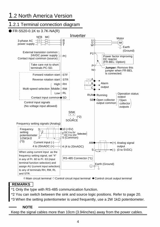
1.2 North America Version
1.2.1 Terminal connection diagramFR-S520-0.1K to 3.7K-NA(R)
Power factor improving DC reactor(FR-BEL: Option)
3-phase ACpower supply
NFBRST
PCExternal transistor common
24VDC power supplyContact input common (source)
STF
STR
RH
RM
RL
SD
Forward rotation start
Reverse rotation start
Middle
High
Low
Frequency setting signals (Analog)
10 (+5V)
22
3
1
4 to 20mADC (+) 4 (4 to 20mADC)
Frequencysettingpotentiometer1/2W1k(*3)
RUN
SE
Running
Control input signals(No voltage input allowed)
Jumper: Remove this jumper when FR-BEL is connected.
Motor
IM
Earth(Ground)
Alarmoutput
A
B
C
UVW
P1
P
N
Selected
Multi-speed selection
Operation status outputContact input common
5 (Common)
Open collectoroutput common
Current input (-)
MC
Opencollectoroutputs
SINK
SOURCE
Inverter
Main circuit terminal Control circuit input terminal Control circuit output terminal
DC 0 to 5VDC 0 to 10V
(*2)
When using current input as the frequency setting signal, set "4" in any of Pr. 60 to Pr. 63 (input terminal function selection) and assign AU (current input selection) to any of terminals RH, RM, RL and STR.
Earth (Ground)
RS-485 Connector (*1)
AM
5
(+)
(-)
Analog signal output(0 to 5VDC)
Take care not to shortterminals PC-SD.
REMARKS
*1 Only the type with RS-485 communication function.*2 You can switch between the sink and source logic positions. Refer to page 20.*3 When the setting potentiometer is used frequently, use a 2W 1kΩ potentiometer.
NOTEKeep the signal cables more than 10cm (3.94inches) away from the power cables.
5
1
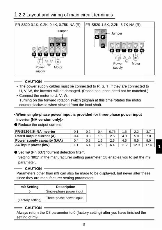
1.2.2 Layout and wiring of main circuit terminals
FR-S520-0.1K, 0.2K, 0.4K, 0.75K-NA (R) FR-S520-1.5K, 2.2K, 3.7K-NA (R)
P1
U V W
IM
R S T
N P
Jumper
Powersupply
Motor
P1
Jumper
R S T U V W
IM
N P
Powersupply
Motor
CAUTION• The power supply cables must be connected to R, S, T. If they are connected to
U, V, W, the inverter will be damaged. (Phase sequence need not be matched.)• Connect the motor to U, V, W.
Turning on the forward rotation switch (signal) at this time rotates the motorcounterclockwise when viewed from the load shaft.
<When single-phase power input is provided for three-phase power inputinverter (NA version only)>Reduce the output current.
FR-S520- K-NA inverter 0.1 0.2 0.4 0.75 1.5 2.2 3.7Rated output current (A) 0.4 0.8 1.5 2.5 4.0 5.0 7.0Power supply capacity (kVA) 0.4 0.8 1.5 2.5 4.5 5.5 9.0AC input power (kW) 1.1 6.4 4.5 6.4 11.2 12.9 17.4
Set m9 (Pr. 637) "current detection filter".Setting "801" in the manufacturer setting parameter C8 enables you to set the m9parameter.
CAUTIONParameters other than m9 can also be made to be displayed, but never alter thesesince they are manufacturer setting parameters.
m9 Setting Description0 Single-phase power input
- - -(Factory setting)
Three-phase power input
CAUTIONAlways return the C8 parameter to 0 (factory setting) after you have finished thesetting of m9.
6
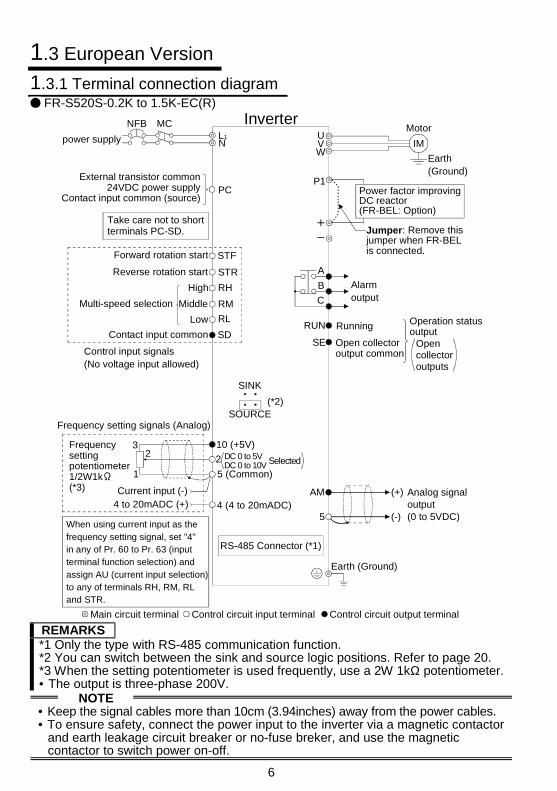
1.3 European Version
1.3.1 Terminal connection diagramFR-S520S-0.2K to 1.5K-EC(R)
Power factor improving DC reactor(FR-BEL: Option)
power supply
NFBL1N
PCExternal transistor common
24VDC power supplyContact input common (source)
STF
STR
RH
RM
RL
SD
Forward rotation start
Reverse rotation start
Middle
High
Low
Frequency setting signals (Analog)
10 (+5V)
22
3
1
4 to 20mADC (+) 4 (4 to 20mADC)
Frequencysettingpotentiometer1/2W1k(*3)
RUN
SE
Running
Control input signals(No voltage input allowed)
Jumper: Remove this jumper when FR-BEL is connected.
Motor
IM
Earth(Ground)
Alarmoutput
A
B
C
UVW
P1
Selected
Multi-speed selection
Operation status outputContact input common
5 (Common)
Open collectoroutput common
Current input (-)
MC
Opencollectoroutputs
SINK
SOURCE
Inverter
Main circuit terminal Control circuit input terminal Control circuit output terminal
DC 0 to 5VDC 0 to 10V
(*2)
When using current input as the frequency setting signal, set "4" in any of Pr. 60 to Pr. 63 (input terminal function selection) and assign AU (current input selection) to any of terminals RH, RM, RL and STR.
Earth (Ground)
RS-485 Connector (*1)
AM
5
(+)
(-)
Analog signal output(0 to 5VDC)
Take care not to shortterminals PC-SD.
REMARKS*1 Only the type with RS-485 communication function.*2 You can switch between the sink and source logic positions. Refer to page 20.*3 When the setting potentiometer is used frequently, use a 2W 1kΩ potentiometer.• The output is three-phase 200V.
NOTE• Keep the signal cables more than 10cm (3.94inches) away from the power cables.• To ensure safety, connect the power input to the inverter via a magnetic contactor
and earth leakage circuit breaker or no-fuse breker, and use the magneticcontactor to switch power on-off.
7
1
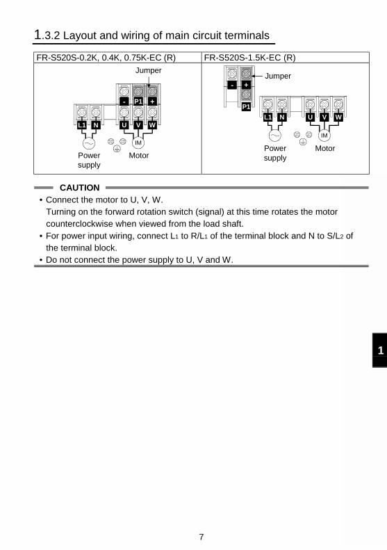
1.3.2 Layout and wiring of main circuit terminals
FR-S520S-0.2K, 0.4K, 0.75K-EC (R) FR-S520S-1.5K-EC (R)
P1
U V W
IM
+-
L1 N
Powersupply
Motor
Jumper
P1
U V W
IM
+-
L1 N
Jumper
Powersupply
Motor
CAUTION• Connect the motor to U, V, W.
Turning on the forward rotation switch (signal) at this time rotates the motorcounterclockwise when viewed from the load shaft.
• For power input wiring, connect L1 to R/L1 of the terminal block and N to S/L2 ofthe terminal block.
• Do not connect the power supply to U, V and W.
8
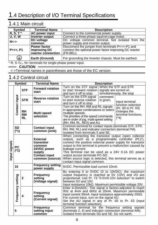
1.4 Description of I/O Terminal Specifications
1.4.1 Main circuitSymbol Terminal Name Description
R, S, T * AC power input Connect to the commercial power supply.U, V, W Inverter output Connect a three-phase squirrel-cage motor.
N<-> DC voltagecommon
DC voltage common terminal. Not isolated from thepower supply and inverter output.
P<+>, P1Power factorimproving DCreactor connection
Disconnect the jumper from terminals P<+>-P1 andconnect the optional power factor improving DC reactor(FR-BEL).
Earth (Ground) For grounding the inverter chassis. Must be earthed.
* R, S <L1, N> terminals for single-phase power input.CAUTION
< >Terminal names in parentheses are those of the EC version.
1.4.2 Control circuitSymbol Terminal Name Description
STF Forward rotationstart
Turn on the STF signalto start forward rotationand turn it off to stop.
When the STF and STRsignals are turned onsimultaneously, the stop
STR Reverse rotationstart
Turn on the STR signalto start reverse rotationand turn it off to stop.
commandis given.
Co
nta
ct i
np
ut
RHRMRL
Multi-speedselection
Turn on the RH, RM and RL signalsin appropriate combinations to selectmultiple speeds.The priorities of the speed commandsare in order of jog, multi-speed setting(RH, RM, RL, REX) and AU.
Input terminalfunction selection(Pr. 60 to Pr. 63)changes theterminal functions.(*4)
SD(*1)
Contact inputcommon (sink)
Common terminal for contact inputs (terminals STF, STR,RH, RM, RL) and indicator connection (terminal FM).Isolated from terminals 5 and SE.
PC(*1)
Externaltransistorcommon24VDC powersupplyContact inputcommon (source)
When connecting the transistor output (open collectoroutput), such as a programmable controller (PLC),connect the positive external power supply for transistoroutput to this terminal to prevent a malfunction caused byleakage current.This terminal can be used as a 24V 0.1A DC poweroutput across terminals PC-SD.When source logic is selected, this terminal serves as acontact input signal common.
10 Frequency settingpower supply 5VDC. Permissible load current 10mA.
2Frequencysetting(Voltage signal)
By entering 0 to 5VDC (0 to 10VDC), the maximumoutput frequency is reached at 5V (10V) and I/O areproportional. Use Pr. 73 "0-5V/0-10V selection" to switchbetween 5V and 10V.Input resistance 10kΩ. Maximum permissible voltage 20V.
Fre
qu
enc
y s
etti
ng
4Frequencysetting(Current signal)
Enter 4-20mADC. This signal is factory-adjusted to reach0Hz at 4mA and 60Hz at 20mA. Maximum permissibleinput current 30mA. Input resistance approximately 250Ω.For current input, turn on the signal AU.Set the AU signal in any of Pr. 60 to Pr. 63 (inputterminal function selection).
Inp
ut
sig
nal
s
5Frequencysetting inputcommon
Common terminal for the frequency setting signals(terminals 2, 4) and indicator connection (terminal AM).Isolated from terminals SD and SE. Do not earth.
9
1
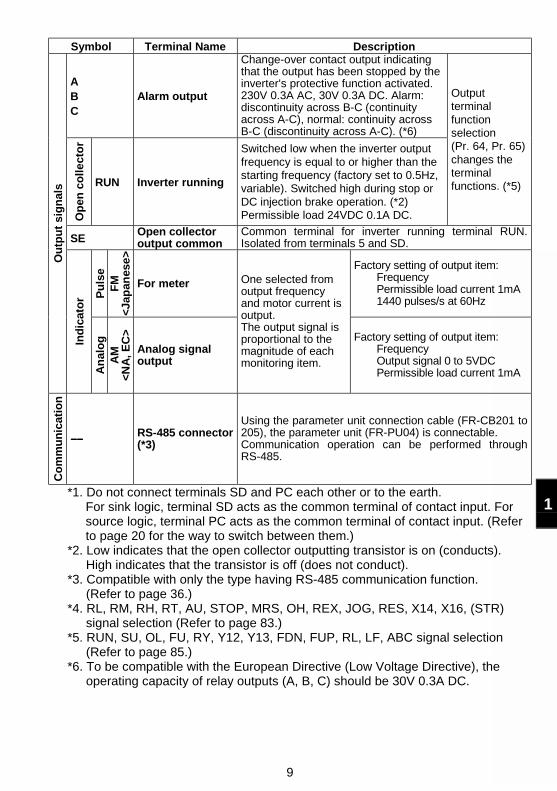
Symbol Terminal Name Description
ABC
Alarm output
Change-over contact output indicatingthat the output has been stopped by theinverter's protective function activated.230V 0.3A AC, 30V 0.3A DC. Alarm:discontinuity across B-C (continuityacross A-C), normal: continuity acrossB-C (discontinuity across A-C). (*6)
Op
en c
oll
ect
or
RUN Inverter running
Switched low when the inverter outputfrequency is equal to or higher than thestarting frequency (factory set to 0.5Hz,variable). Switched high during stop orDC injection brake operation. (*2)Permissible load 24VDC 0.1A DC.
Outputterminalfunctionselection(Pr. 64, Pr. 65)changes theterminalfunctions. (*5)
SEOpen collectoroutput common
Common terminal for inverter running terminal RUN.Isolated from terminals 5 and SD.
Pu
lse
FM
<Ja
pan
ese
>
For meter
Factory setting of output item:FrequencyPermissible load current 1mA1440 pulses/s at 60Hz
Ou
tpu
t si
gn
als
Ind
icat
or
An
alo
gA
M<
NA
, E
C>
Analog signaloutput
One selected fromoutput frequencyand motor current isoutput.The output signal isproportional to themagnitude of eachmonitoring item.
Factory setting of output item:FrequencyOutput signal 0 to 5VDCPermissible load current 1mA
Co
mm
un
icat
ion
−−−−−−−− RS-485 connector(*3)
Using the parameter unit connection cable (FR-CB201 to205), the parameter unit (FR-PU04) is connectable.Communication operation can be performed throughRS-485.
*1. Do not connect terminals SD and PC each other or to the earth.For sink logic, terminal SD acts as the common terminal of contact input. Forsource logic, terminal PC acts as the common terminal of contact input. (Referto page 20 for the way to switch between them.)
*2. Low indicates that the open collector outputting transistor is on (conducts).High indicates that the transistor is off (does not conduct).
*3. Compatible with only the type having RS-485 communication function.(Refer to page 36.)
*4. RL, RM, RH, RT, AU, STOP, MRS, OH, REX, JOG, RES, X14, X16, (STR)signal selection (Refer to page 83.)
*5. RUN, SU, OL, FU, RY, Y12, Y13, FDN, FUP, RL, LF, ABC signal selection(Refer to page 85.)
*6. To be compatible with the European Directive (Low Voltage Directive), theoperating capacity of relay outputs (A, B, C) should be 30V 0.3A DC.
10
1.5 How to Use the Main Circuit Terminals
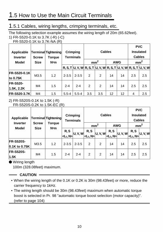
1.5.1 Cables, wiring lengths, crimping terminals, etc.The following selection example assumes the wiring length of 20m (65.62feet).1) FR-S520-0.1K to 3.7K (-R) (-C)
FR-S520-0.1K to 3.7K-NA (R)
Cables
PVC
Insulated
Cables
Crimping
Terminals
mm2 AWG mm2
Applicable
Inverter
Model
Terminal
Screw
Size
Tightening
Torque
N m
R, S, T U, V, W R, S, T U, V, W R, S, T U, V, W R, S, T U, V, W
FR-S520-0.1K
to 0.75KM3.5 1.2 2-3.5 2-3.5 2 2 14 14 2.5 2.5
FR-S520-
1.5K, 2.2KM4 1.5 2-4 2-4 2 2 14 14 2.5 2.5
FR-S520-3.7K M4 1.5 5.5-4 5.5-4 3.5 3.5 12 12 4 2.5
2) FR-S520S-0.1K to 1.5K (-R)FR-S520S-0.2K to 1.5K-EC (R)
Cables
PVC
Insulated
Cables
Crimping
Terminals
mm2 AWG mm2
Applicable
Inverter
Model
Terminal
Screw
Size
Tightening
Torque
N mR, S
<L1, N>U, V, W
R, S
<L1, N>U, V, W
R, S
<L1, N>U, V, W
R, S
<L1, N>U, V, W
FR-S520S-
0.1K to 0.75KM3.5 1.2 2-3.5 2-3.5 2 2 14 14 2.5 2.5
FR-S520S-
1.5KM4 1.5 2-4 2-4 2 2 14 14 2.5 2.5
Wiring length100m (328.08feet) maximum.
CAUTION
• When the wiring length of the 0.1K or 0.2K is 30m (98.43feet) or more, reduce thecarrier frequency to 1kHz.
• The wiring length should be 30m (98.43feet) maximum when automatic torqueboost is selected in Pr. 98 "automatic torque boost selection (motor capacity)".(refer to page 104)
11
1
1.5.2 Wiring instructions1) Use insulation-sleeved crimping terminals for the power supply and motor cables.
2) Application of power to the output terminals (U, V, W) of the inverter will damagethe inverter. Never perform such wiring.
3) After wiring, wire off-cuts must not be left in the inverter.Wire off-cuts can cause an alarm, failure or malfunction. Always keep the inverterclean.When drilling a control box etc., take care not to let wire off-cuts enter the inverter.
4) Use cables of the recommended size to make a voltage drop 2% maximum.If the wiring distance is long between the inverter and motor, a main circuit cablevoltage drop will cause the motor torque to decrease especially at the output of alow frequency.
5) For long distance wiring, the fast-response current limit function may be reduced orthe devices connected to the secondary side may malfunction or become faultyunder the influence of a charging current due to the stray capacity of wiring.Therefore, note the maximum overall wiring length.
6) Electromagnetic wave interferenceThe input/output (main circuit) of the inverter includes harmonic components, whichmay interfere with the communication devices (such as AM radios) used near theinverter. In this case, install the optional FR-BIF radio noise filter (for use in theinput side only) or FR-BSF01 or FR-BLF line noise filter to minimize interference.
7) Do not install a power capacitor, surge suppressor or radio noise filter (FR-BIFoption) in the output side of the inverter.This will cause the inverter to trip or the capacitor and surge suppressor to bedamaged. If any of the above devices are connected, remove them. (When usingthe FR-BIF radio noise filter with a single-phase power supply, connect it to theinput side of the inverter after isolating the T <L3> phase securely.)
8) Before starting rewiring or other work after performing operation once, check thevoltage with a meter etc. more than 10 minutes after power-off. For some time afterpower-off, there is a dangerous voltage in the capacitor.
12
1.5.3 Peripheral devices
(1) Selection of peripheral devicesCheck the capacity of the motor applicable to the inverter you purchased. Appropriateperipheral devices must be selected according to the capacity.Refer to the following list and prepare appropriate peripheral devices:1) FR-S520-0.1K to 3.7K (-R) (-C)
FR-S520-0.1K to 3.7K-NA (R)Cables (mm2)
(*2)MotorOutput
(kW(HP))
InverterModel
No-Fuse Breaker(NFB*1) or EarthLeakage CircuitBreaker (ELB)(Refer to page
13)
MagneticContactor
(MC)(Refer topage 15)
PowerFactor
ImprovingAC Reactor
(Refer topage 16)
PowerFactor
ImprovingDC Reactor
(Refer topage 16)
R, S, T U, V, W
0.1(1/8)
FR-S520-0.1K
30AF/5AT S-N10FR-BAL-0.4K
(*3)FR-BEL-0.4K
(*3)2 2
0.2(1/4)
FR-S520-0.2K
30AF/5AT S-N10FR-BAL-0.4K
(*3)FR-BEL-0.4K
(*3)2 2
0.4(1/2)
FR-S520-0.4K
30AF/5AT S-N10 FR-BAL-0.4K FR-BEL-0.4K 2 2
0.75(1)
FR-S520-0.75K
30AF/10AT S-N10FR-BAL-
0.75KFR-BEL-
0.75K2 2
1.5(2)
FR-S520-1.5K
30AF/15AT S-N10 FR-BAL-1.5K FR-BEL-1.5K 2 2
2.2(3)
FR-S520-2.2K
30AF/20ATS-N11,S-N12
FR-BAL-2.2K FR-BEL-2.2K 2 2
3.7(5)
FR-S520-3.7K
30AF/30AT S-N20 FR-BAL-3.7K FR-BAL-3.7K 3.5 3.5
2) FR-S520S-0.1K to 1.5K (-R)FR-S520S-0.2K to 1.5K-EC (R)
Cables (mm2)(*2)Motor
Output(kW
(HP))
InverterModel
No-Fuse Breaker(NFB*1) or EarthLeakage CircuitBreaker (ELB)(Refer to page
13)
MagneticContactor
(MC)(Refer topage 15)
PowerFactor
ImprovingAC Reactor
(Refer topage 16)
PowerFactor
ImprovingDC Reactor
(Refer topage 16)
R, S<L1, N>
U, V, W
0.1(1/8)
FR-S520S-0.1K
30AF/5AT S-N10FR-BAL-0.4K
(*3)FR-BEL-0.4K
(*3)2 2
0.2(1/4)
FR-S520S-0.2K
30AF/10AT S-N10FR-BAL-0.4K
(*3)FR-BEL-0.4K
(*3)2 2
0.4(1/2)
FR-S520S-0.4K
30AF/10AT S-N20FR-BAL-0.75K (*3)
FR-BEL-0.75K (*3)
2 2
0.75(1)
FR-S520S-0.75K
30AF/15AT S-N20FR-BAL-1.5K
(*3)FR-BEL-1.5K
(*3)2 2
1.5(2)
FR-S520S-1.5K
30AF/20AT S-N21FR-BAL-2.2K
(*3)FR-BEL-2.2K
(*3)2 2
*1 Choose the NFB type to meet the power supply capacity.*2 The size of the cables assume that the wiring length is 20m (65.62feet).*3 The power factor may be slightly less.
13
1
1.5.4 Leakage current and installation of earth leakage circuit breaker
Due to static capacitances existing in the inverter I/O wiring and motor, leakagecurrents flow through them. Since their values depend on the static capacitances,carrier frequency, etc., take the following counter measures.
(1) To-ground leakage currentsLeakage currents may flow not only into the inverter's own line but also into theother line through the ground cable, etc.These leakage currents may operate earth leakage circuit breakers and earthleakage relays unnecessarily.
Counter measures If the carrier frequency setting is high, decrease the carrier frequency (Pr. 72) ofthe inverter.Note that motor noise increases. Selection of Soft-PWM control (Pr. 70) will makeit unoffending. (Factory setting)
By using earth leakage circuit breakers designed for harmonic and surgesuppression (e.g. Mitsubishi's Progressive Super Series) in the inverter's own lineand other line, operation can be performed with the carrier frequency kept high(with low noise).
(2) Line-to-line leakage currentsHarmonics of leakagecurrents flowing in staticcapacities between theinverter output cablesmay operate the externalthermal relayunnecessarily.
Line-to-Line Leakage Current Path
InverterPower supply
IM
Thermal relay
Line static capacitances
NFB Motor
Counter measures Use the electronic overcurrent protection of the inverter. Decrease the carrier frequency. Note that motor noise increases. Selection ofSoft-PWM (Pr. 70) makes it unoffending.To ensure that the motor is protected against line-to-line leakage currents, it isrecommended to use a temperature sensor to directly detect motor temperature.
Installation and selection of no-fuse breakerOn the power receiving side, install a no-fuse breaker (NFB) to protect the primarywiring of the inverter. Which NFB to choose depends on the power supply sidepower factor (which changes with the power supply voltage, output frequency andload) of the inverter. Especially as the completely electromagnetic type NFBchanges in operational characteristic with harmonic currents, you need to choosethe one of a little larger capacity. (Check the data of the corresponding breaker.)For the earth leakage circuit breaker, use our product designed for harmonic andsurge suppression (Progressive Super Series). (Refer to page 12 for therecommended models.)
CAUTION
Choose the NFB type according to the power supply capacity.
14
(3) Selecting the rated sensitivity current for the earth leakage circuitbreaker
When using the earth leakage circuit breaker with the inverter circuit, select its ratedsensitivity current as follows, independently of the PWM carrier frequency:
Progressive Super Series(Type SP, CF, SF, CP)Rated sensitivity current:I∆n ≥ 10 × (lg1+Ign+lg2+lgm)Conventional NV series (Type CA,CS, SS produced prior to '91)Rated sensitivity current:I∆n ≥ 10 × lg1+lgn+3 × (lg2+lgm)lg1, lg2 : Leakage currents of cable
path during commercialpower supply operation
lgn* : Leakage current of noisefilter on inverter input side
lgm : Leakage current of motorduring commercial powersupply operation
0
20
40
60
80
100
120
2 3.5 8 142238 80
5.5 30 60100
150 1.5 3.7
2.2
7.5 1522
11
37
30
55
455.5 18.5
Cable size (mm )
2.0
1.00.70.5
0.3
0.2
0.1
Motor capacity (kW)
Example of leakage current per 1km in cable path during commercial power supply operation when the CV cable is routed in metal conduit (200V 60Hz)
Lea
kage
cur
rent
(m
A)
Lea
kage
cur
rent
(m
A)
2
Leakage current example of 3-phase induction motor during commercial power supply operation (200V 60Hz)
<Example>
NV
Ig1 Ign Ig2 Igm
2mm ×5m 2mm ×70m
IM3200V1.5kW(2HP)
Inver-ter
Noise filter
2 2
(16.40feet) (229.66feet)
CAUTION• The earth leakage circuit breaker should be installed to the primary (power
supply) side of the inverter.• In the connection neutral point grounded system, the sensitivity current
becomes worse for ground faults in the inverter secondary side. Hence, theprotective grounding of the load equipment should be 10Ω or less.
• When the breaker is installed in the secondary side of the inverter, it may beunnecessarily operated by harmonics if the effective value is less than the rating. In thiscase, do not install the breaker since the eddy current and hysteresis loss increase andthe temperature rises.* Note the leakage current value of the noise filter installed on the inverter input
side.Progressive Super Series
(Type SP, CF, SF,CP)Conventional NV
(Type CA, CS, SS)5m (16.40feet)Leakage current (Ig1) (mA) 20 × 1000m (3280.80feet) = 0.10
Leakage current (Ign) (mA) 0 (without noise filter)70m (229.66feet)Leakage current (Ig2) (mA) 20 × 1000m (3280.80feet) = 1.40
Motor leakagecurrent (Igm) (mA) 0.14
Total leakage current (mA) 1.66 4.78Rated sensitivity current(mA) ( ≥≥≥≥ Ig ×××× 10) 30 100
15
1
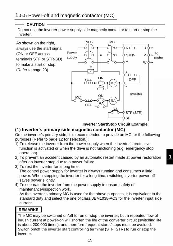
1.5.5 Power-off and magnetic contactor (MC)
CAUTIONDo not use the inverter power supply side magnetic contactor to start or stop theinverter.
As shown on the right,always use the start signal(ON or OFF acrossterminals STF or STR-SD)to make a start or stop.(Refer to page 23)
Power supply
NFB
F
OFFON
MCMC
RA
R<L1>
S<N>
T
U
V
W
Inverter
STF (STR)
SD
MC
To motor
OFF
ON
RARA
MC
OFF
B
C
Inverter Start/Stop Circuit Example
(1) Inverter's primary side magnetic contactor (MC)On the inverter's primary side, it is recommended to provide an MC for the followingpurposes (Refer to page 12 for selection.):1) To release the inverter from the power supply when the inverter's protective
function is activated or when the drive is not functioning (e.g. emergency stopoperation).
2) To prevent an accident caused by an automatic restart made at power restorationafter an inverter stop due to a power failure.
3) To rest the inverter for a long time.The control power supply for inverter is always running and consumes a littlepower. When stopping the inverter for a long time, switching inverter power offsaves power slightly.
4) To separate the inverter from the power supply to ensure safety ofmaintenance/inspection work.As the inverter's primary MC is used for the above purposes, it is equivalent to thestandard duty and select the one of class JEM1038-AC3 for the inverter input sidecurrent.
REMARKS
The MC may be switched on/off to run or stop the inverter, but a repeated flow ofinrush current at power-on will shorten the life of the converter circuit (switching lifeis about 200,000 times), and therefore frequent starts/stops must be avoided.Switch on/off the inverter start controlling terminal (STF, STR) to run or stop theinverter.
16
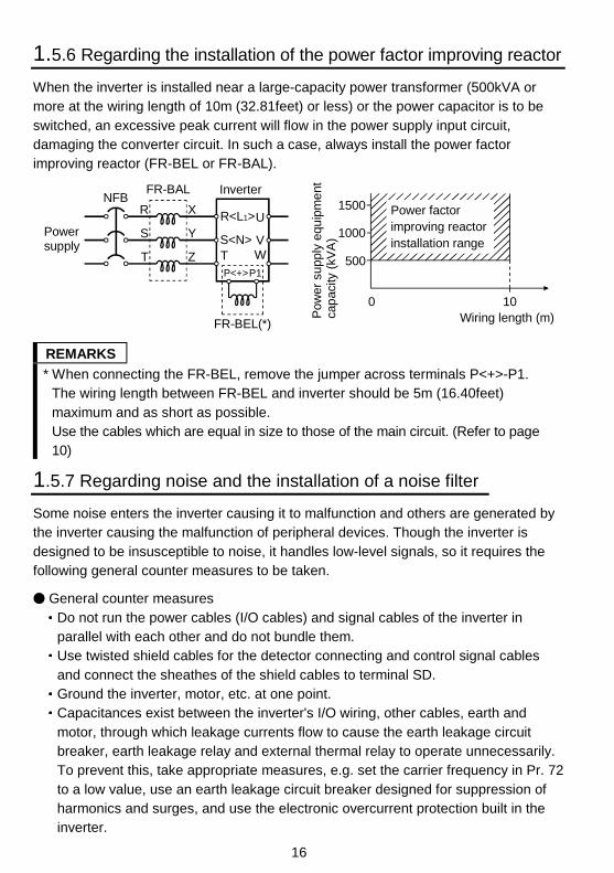
1.5.6 Regarding the installation of the power factor improving reactor
When the inverter is installed near a large-capacity power transformer (500kVA ormore at the wiring length of 10m (32.81feet) or less) or the power capacitor is to beswitched, an excessive peak current will flow in the power supply input circuit,damaging the converter circuit. In such a case, always install the power factorimproving reactor (FR-BEL or FR-BAL).
NFBInverterFR-BAL
Power supply
R
S
T Z
Y
X R<L1>
S<N>T
U
VW
P<+>P1
FR-BEL(*)
0 10Wiring length (m)
500
1500
1000
Pow
er s
uppl
y eq
uip
me
nt
cap
acity
(kV
A)
Power factor improving reactorinstallation range
REMARKS
* When connecting the FR-BEL, remove the jumper across terminals P<+>-P1.The wiring length between FR-BEL and inverter should be 5m (16.40feet)maximum and as short as possible.Use the cables which are equal in size to those of the main circuit. (Refer to page10)
1.5.7 Regarding noise and the installation of a noise filter
Some noise enters the inverter causing it to malfunction and others are generated bythe inverter causing the malfunction of peripheral devices. Though the inverter isdesigned to be insusceptible to noise, it handles low-level signals, so it requires thefollowing general counter measures to be taken.
General counter measuresDo not run the power cables (I/O cables) and signal cables of the inverter inparallel with each other and do not bundle them.Use twisted shield cables for the detector connecting and control signal cablesand connect the sheathes of the shield cables to terminal SD.Ground the inverter, motor, etc. at one point.Capacitances exist between the inverter's I/O wiring, other cables, earth andmotor, through which leakage currents flow to cause the earth leakage circuitbreaker, earth leakage relay and external thermal relay to operate unnecessarily.To prevent this, take appropriate measures, e.g. set the carrier frequency in Pr. 72to a low value, use an earth leakage circuit breaker designed for suppression ofharmonics and surges, and use the electronic overcurrent protection built in theinverter.
17
1
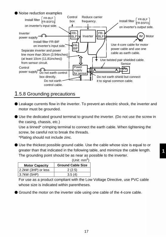
Noise reduction examples
Inverter
FR-BIF
Sensor
Use 4-core cable for motor power cable and use one cable as earth cable.
Power supplyfor sensor
Use twisted pair shielded cable.
Inverter power supply
Control power supply
Do not earth shield but connect it to signal common cable.
Separate inverter and power line more than 30cm (3.94inches)(at least 10cm (11.81inches)) from sensor circuit.
Install filter FR-BIF on inverter's input side.
Controlbox
Reduce carrier frequency.
MotorIMFR-BLF
FR-BLF
FR-BLFFR-BSF01
Do not earth control box directly.
Do not earth control cable.
FR-BLFFR-BSF01
Install filter
on inverter's input side.
Install filter
on inverter's output side.
1.5.8 Grounding precautions
Leakage currents flow in the inverter. To prevent an electric shock, the inverter andmotor must be grounded.
Use the dedicated ground terminal to ground the inverter. (Do not use the screw inthe casing, chassis, etc.)Use a tinned* crimping terminal to connect the earth cable. When tightening thescrew, be careful not to break the threads.*Plating should not include zinc.
Use the thickest possible ground cable. Use the cable whose size is equal to orgreater than that indicated in the following table, and minimize the cable length.The grounding point should be as near as possible to the inverter.
(Unit: mm2)
Motor Capacity Ground Cable Size2.2kW (3HP) or less 2 (2.5)3.7kW (5HP) 3.5 (4)
For use as a product compliant with the Low Voltage Directive, use PVC cablewhose size is indicated within parentheses.
Ground the motor on the inverter side using one cable of the 4-core cable.
18
1.5.9 Regarding power harmonics and Japanese power harmonicsuppression guideline
The inverter may generate power harmonics from its converter circuit to affect thepower generator, power capacitor etc. Power harmonics are different from noise andleakage currents in source, frequency band and transmission path. Take the followingcounter measure suppression techniques.
The following table indicates differences between harmonics and noise:Item Harmonics Noise
Frequency Normally 40th to 50th degrees,3kHz max.
High frequency (several 10kHzto MHz order)
Environment To-electric channel, powerimpedance To-space, distance, wiring path
Quantitativeunderstanding Theoretical calculation possible Random occurrence, quantitative
grasping difficult
Generated amount Nearly proportional to loadcapacity
Change with current variationratio (larger as switching speedincreases)
Affected equipmentimmunity
Specified in standard perequipment
Different depending on maker'sequipment specifications
Suppression example Provide reactor. Increase distance.
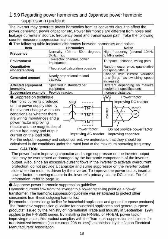
Suppression techniqueHarmonic currents producedon the power supply side bythe inverter change with suchconditions as whether thereare wiring impedances and apower factor improvingreactor and the magnitudes ofoutput frequency and outputcurrent on the load side.
Inve
rter
NFB
Power factor improving AC reactor
Do not provide power factor improving capacitor.
Power factor improving DC reactor
Motor
IM
For the output frequency and output current, we understand that they should becalculated in the conditions under the rated load at the maximum operating frequency.
CAUTIONThe power factor improving capacitor and surge suppressor on the inverter outputside may be overheated or damaged by the harmonic components of the inverteroutput. Also, since an excessive current flows in the inverter to activate overcurrentprotection, do not provide a capacitor and surge suppressor on the inverter outputside when the motor is driven by the inverter. To improve the power factor, insert apower factor improving reactor in the inverter's primary side or DC circuit. For fullinformation, refer to page 16.
Japanese power harmonic suppression guidelineHarmonic currents flow from the inverter to a power receiving point via a powertransformer. The harmonic suppression guideline was established to protect otherconsumers from these outgoing harmonics.[Harmonic suppression guideline for household appliances and general-purpose products]The "harmonic suppression guideline for household appliances and general-purposeproducts" issued by the Ministry of International Trade and Industry in September, 1994applies to the FR-S500 series. By installing the FR-BEL or FR-BAL power factorimproving reactor, this product complies with the "harmonic suppression techniques fortransistorized inverters (input current 20A or less)" established by the Japan ElectricalManufacturers' Association.
19
1
1.6 How to Use the Control Circuit Terminals
1.6.1 Terminal block layout
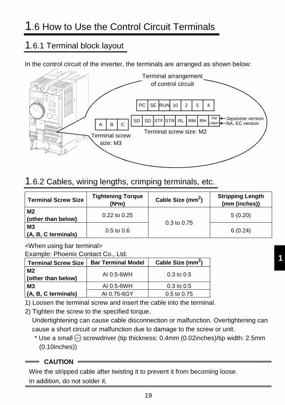
In the control circuit of the inverter, the terminals are arranged as shown below:
Terminal screw size: M2
10 2 5 4
RL RM RHFM
Terminal arrangement of control circuit
<AM>Japanese versionNA, EC version
Terminal screw size: M3
A
RUN
STR
PC SE
SD SD STFB C
1.6.2 Cables, wiring lengths, crimping terminals, etc.
Terminal Screw SizeTightening Torque
(N m)Cable Size (mm2)
Stripping Length(mm (inches))
M2(other than below)
0.22 to 0.25 5 (0.20)
M3(A, B, C terminals)
0.5 to 0.60.3 to 0.75
6 (0.24)
<When using bar terminal>Example: Phoenix Contact Co., Ltd.Terminal Screw Size Bar Terminal Model Cable Size (mm2)
M2(other than below)
AI 0.5-6WH 0.3 to 0.5
AI 0.5-6WH 0.3 to 0.5M3(A, B, C terminals) AI 0.75-6GY 0.5 to 0.75
1) Loosen the terminal screw and insert the cable into the terminal.2) Tighten the screw to the specified torque.
Undertightening can cause cable disconnection or malfunction. Overtightening cancause a short circuit or malfunction due to damage to the screw or unit.* Use a small screwdriver (tip thickness: 0.4mm (0.02inches)/tip width: 2.5mm
(0.10inches))
CAUTION
Wire the stripped cable after twisting it to prevent it from becoming loose.
In addition, do not solder it.
20
1.6.3 Wiring instructions
1) Terminals SD, SE and 5 are common to the I/O signals. These common terminalsmust not be earthed.
2) Use shielded or twisted cables for connection to the control circuit terminals and runthem away from the main and power circuits (including the 200V relay sequencecircuit).
3) The input signals to the control circuit are micro currents. When contacts arerequired, use two or more parallel micro signal contacts or a twin contact to preventa contact fault.
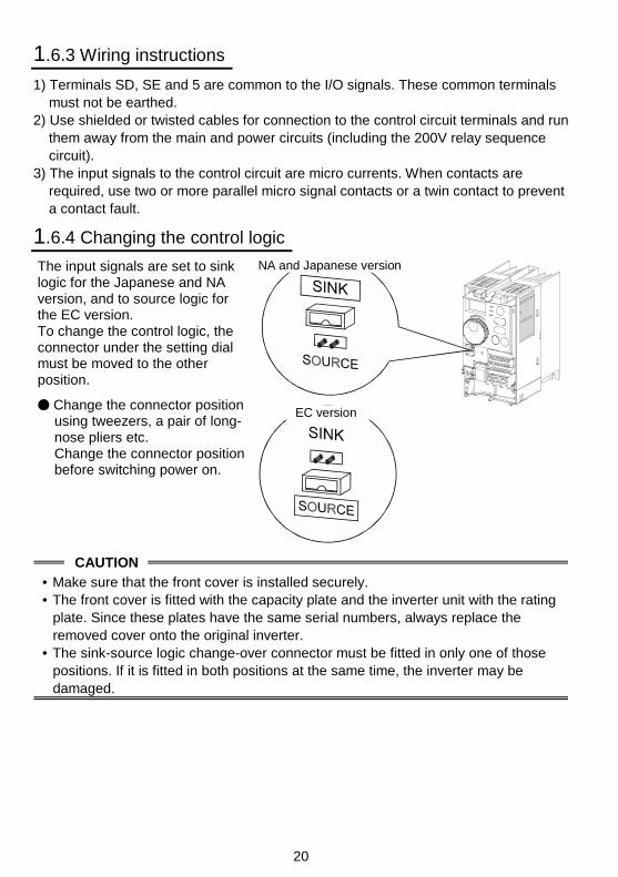
1.6.4 Changing the control logic
The input signals are set to sinklogic for the Japanese and NAversion, and to source logic forthe EC version.To change the control logic, theconnector under the setting dialmust be moved to the otherposition.
Change the connector positionusing tweezers, a pair of long-nose pliers etc.Change the connector positionbefore switching power on.
NA and Japanese version
EC version
CAUTION
• Make sure that the front cover is installed securely.• The front cover is fitted with the capacity plate and the inverter unit with the rating
plate. Since these plates have the same serial numbers, always replace theremoved cover onto the original inverter.
• The sink-source logic change-over connector must be fitted in only one of thosepositions. If it is fitted in both positions at the same time, the inverter may bedamaged.
21
1
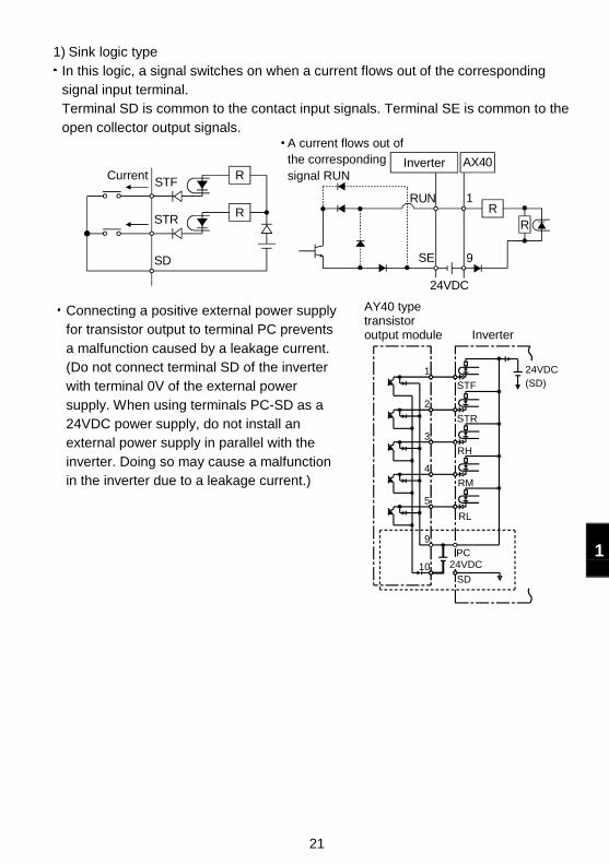
1) Sink logic typeIn this logic, a signal switches on when a current flows out of the correspondingsignal input terminal.Terminal SD is common to the contact input signals. Terminal SE is common to theopen collector output signals.
AX40
SE
RUN
24VDC
STR
STF
SD
R
1
9
R
R R
A current flows out of the corresponding signal RUN
InverterCurrent
Connecting a positive external power supplyfor transistor output to terminal PC preventsa malfunction caused by a leakage current.(Do not connect terminal SD of the inverterwith terminal 0V of the external powersupply. When using terminals PC-SD as a24VDC power supply, do not install anexternal power supply in parallel with theinverter. Doing so may cause a malfunctionin the inverter due to a leakage current.)
1
9
10SD
PC
4
RM
3
RH
2
STR
STF
24VDC(SD)
24VDC
5
RL
AY40 type transistor output module Inverter
22
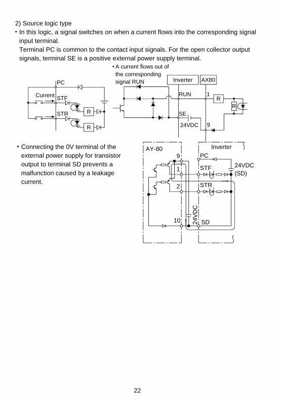
2) Source logic typeIn this logic, a signal switches on when a current flows into the corresponding signalinput terminal.Terminal PC is common to the contact input signals. For the open collector outputsignals, terminal SE is a positive external power supply terminal.
STF
STR
PC AX80
24VDC
RUN
SE
1
9
RR
R
R
A current flows out of the corresponding signal RUN Inverter
Current
Connecting the 0V terminal of theexternal power supply for transistoroutput to terminal SD prevents amalfunction caused by a leakagecurrent.
AY-809 PC
24VDC(SD)
1
2
10
STF
STR
SD24V
DC
Inverter
23
1
1.7 Input Terminals
1.7.1 Run (start) and stop (STF, STR, STOP)
To start and stop the motor, first switch on the input power supply of the inverter(switch on the magnetic contactor, if any, in the input circuit during preparation foroperation), then start the motor with the forward or reverse rotation start signal.
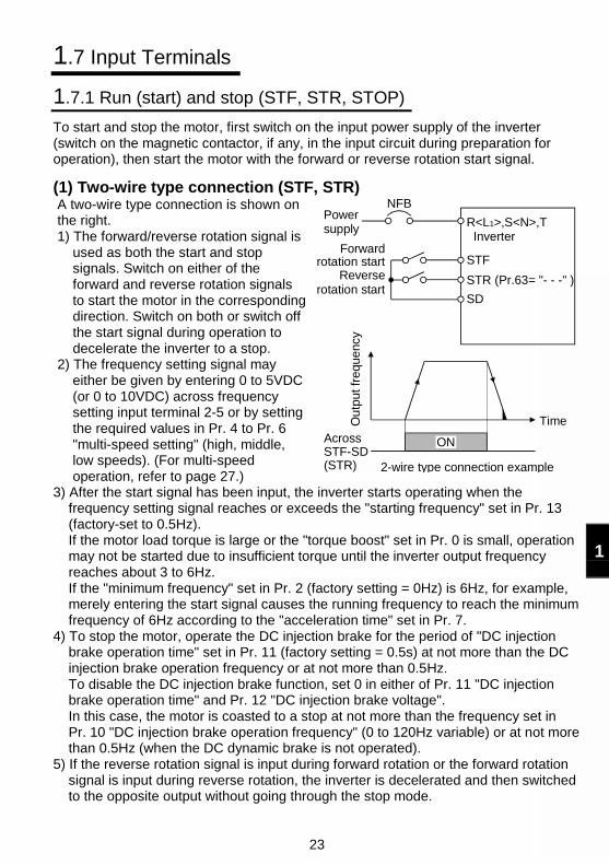
(1) Two-wire type connection (STF, STR)A two-wire type connection is shown onthe right.1) The forward/reverse rotation signal is
used as both the start and stopsignals. Switch on either of theforward and reverse rotation signalsto start the motor in the correspondingdirection. Switch on both or switch offthe start signal during operation todecelerate the inverter to a stop.
2) The frequency setting signal mayeither be given by entering 0 to 5VDC(or 0 to 10VDC) across frequencysetting input terminal 2-5 or by settingthe required values in Pr. 4 to Pr. 6"multi-speed setting" (high, middle,low speeds). (For multi-speedoperation, refer to page 27.)
ON
NFBPower supply
Forward rotation start
Reverse rotation start
STF
STR (Pr.63= "- - -" )
SD
R<L1>,S<N>,T Inverter
Ou
tput
freq
uenc
y
Across STF-SD(STR)
Time
2-wire type connection example
3) After the start signal has been input, the inverter starts operating when thefrequency setting signal reaches or exceeds the "starting frequency" set in Pr. 13(factory-set to 0.5Hz).If the motor load torque is large or the "torque boost" set in Pr. 0 is small, operationmay not be started due to insufficient torque until the inverter output frequencyreaches about 3 to 6Hz.If the "minimum frequency" set in Pr. 2 (factory setting = 0Hz) is 6Hz, for example,merely entering the start signal causes the running frequency to reach the minimumfrequency of 6Hz according to the "acceleration time" set in Pr. 7.
4) To stop the motor, operate the DC injection brake for the period of "DC injectionbrake operation time" set in Pr. 11 (factory setting = 0.5s) at not more than the DCinjection brake operation frequency or at not more than 0.5Hz.To disable the DC injection brake function, set 0 in either of Pr. 11 "DC injectionbrake operation time" and Pr. 12 "DC injection brake voltage".In this case, the motor is coasted to a stop at not more than the frequency set inPr. 10 "DC injection brake operation frequency" (0 to 120Hz variable) or at not morethan 0.5Hz (when the DC dynamic brake is not operated).
5) If the reverse rotation signal is input during forward rotation or the forward rotationsignal is input during reverse rotation, the inverter is decelerated and then switchedto the opposite output without going through the stop mode.
24
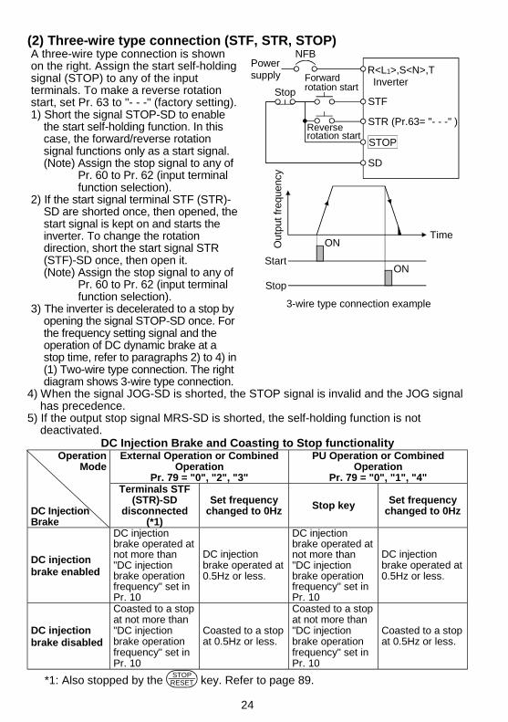
(2) Three-wire type connection (STF, STR, STOP)A three-wire type connection is shownon the right. Assign the start self-holdingsignal (STOP) to any of the inputterminals. To make a reverse rotationstart, set Pr. 63 to "- - -" (factory setting).1) Short the signal STOP-SD to enable
the start self-holding function. In thiscase, the forward/reverse rotationsignal functions only as a start signal.(Note) Assign the stop signal to any of
Pr. 60 to Pr. 62 (input terminalfunction selection).
2) If the start signal terminal STF (STR)-SD are shorted once, then opened, thestart signal is kept on and starts theinverter. To change the rotationdirection, short the start signal STR(STF)-SD once, then open it.(Note) Assign the stop signal to any of
Pr. 60 to Pr. 62 (input terminalfunction selection).
3) The inverter is decelerated to a stop byopening the signal STOP-SD once. Forthe frequency setting signal and theoperation of DC dynamic brake at astop time, refer to paragraphs 2) to 4) in(1) Two-wire type connection. The rightdiagram shows 3-wire type connection.
Reverse rotation start
NFB
Time
STF
STR (Pr.63= "- - -" )
SD
STOP
Start
Stop
ON
ON
Power supply R<L1>,S<N>,T
Inverter
Out
put
freq
uenc
y
Stop
Forward rotation start
3-wire type connection example
4) When the signal JOG-SD is shorted, the STOP signal is invalid and the JOG signalhas precedence.
5) If the output stop signal MRS-SD is shorted, the self-holding function is notdeactivated.
DC Injection Brake and Coasting to Stop functionalityOperation
ModeExternal Operation or Combined
OperationPr. 79 = "0", "2", "3"
PU Operation or CombinedOperation
Pr. 79 = "0", "1", "4"
DC InjectionBrake
Terminals STF(STR)-SD
disconnected(*1)
Set frequencychanged to 0Hz Stop key Set frequency
changed to 0Hz
DC injectionbrake enabled
DC injectionbrake operated atnot more than"DC injectionbrake operationfrequency" set inPr. 10
DC injectionbrake operated at0.5Hz or less.
DC injectionbrake operated atnot more than"DC injectionbrake operationfrequency" set inPr. 10
DC injectionbrake operated at0.5Hz or less.
DC injectionbrake disabled
Coasted to a stopat not more than"DC injectionbrake operationfrequency" set inPr. 10
Coasted to a stopat 0.5Hz or less.
Coasted to a stopat not more than"DC injectionbrake operationfrequency" set inPr. 10
Coasted to a stopat 0.5Hz or less.
*1: Also stopped by the STOP
RESET key. Refer to page 89.
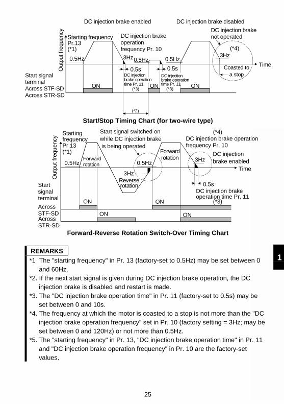
25
1
DC injectionbrake operation time Pr. 11
Out
put f
requ
ency
Starting frequencyPr.13(*1)
0.5Hz
ON
DC injection brakeoperation frequency Pr. 10
3Hz
0.5sDC injectionbrake operationtime Pr. 11
0.5Hz
0.5s
ON
0.5Hz
ON
3Hz
Coasted to a stop
Time
DC injection brake not operated
DC injection brake disabledDC injection brake enabled
Start signalterminalAcross STF-SDAcross STR-SD
(*4)
(*3) (*3)
(*2)
Start/Stop Timing Chart (for two-wire type)
Out
put f
requ
ency
Starting frequencyPr.13(*1)
0.5HzForwardrotation
Forwardrotation 3Hz
3Hz
Start signal switched on while DC injection brake is being operated
DC injection brake operationfrequency Pr. 10
DC injectionbrake enabled
Time
DC injection brake operation time Pr. 11
0.5s
ON
ON ON
ON
Reverserotation
0.5Hz
Start signal terminal
Across STF-SDAcross STR-SD
(*3)
(*4)
Forward-Reverse Rotation Switch-Over Timing Chart
REMARKS
*1 The "starting frequency" in Pr. 13 (factory-set to 0.5Hz) may be set between 0and 60Hz.
*2. If the next start signal is given during DC injection brake operation, the DCinjection brake is disabled and restart is made.
*3. The "DC injection brake operation time" in Pr. 11 (factory-set to 0.5s) may beset between 0 and 10s.
*4. The frequency at which the motor is coasted to a stop is not more than the "DCinjection brake operation frequency" set in Pr. 10 (factory setting = 3Hz; may beset between 0 and 120Hz) or not more than 0.5Hz.
*5. The "starting frequency" in Pr. 13, "DC injection brake operation time" in Pr. 11and "DC injection brake operation frequency" in Pr. 10 are the factory-setvalues.
26
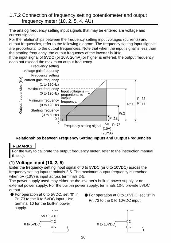
1.7.2 Connection of frequency setting potentiometer and outputfrequency meter (10, 2, 5, 4, AU)
The analog frequency setting input signals that may be entered are voltage andcurrent signals.For the relationships between the frequency setting input voltages (currents) andoutput frequencies, refer to the following diagram. The frequency setting input signalsare proportional to the output frequencies. Note that when the input signal is less thanthe starting frequency, the output frequency of the inverter is 0Hz.If the input signal of 5VDC (or 10V, 20mA) or higher is entered, the output frequencydoes not exceed the maximum output frequency.
Maximum frequency(0 to 120Hz)
Minimum frequency(0 to 120Hz)
Starting frequency(0 to 60Hz)
0.50
Out
put f
requ
enci
es (
Hz)
Input voltage is proportional to output frequency.
Pr.38Pr.39Pr.1
Pr.2
Pr.13
Pr.735V(10V)
(20mA)
Frequency setting signal
Frequency settingvoltage gain frequency
Frequency settingcurrent gain frequency
(1 to 120Hz)
Relationships between Frequency Setting Inputs and Output Frequencies
REMARKSFor the way to calibrate the output frequency meter, refer to the instruction manual(basic).
(1) Voltage input (10, 2, 5)Enter the frequency setting input signal of 0 to 5VDC (or 0 to 10VDC) across thefrequency setting input terminals 2-5. The maximum output frequency is reachedwhen 5V (10V) is input across terminals 2-5.The power supply used may either be the inverter's built-in power supply or anexternal power supply. For the built-in power supply, terminals 10-5 provide 5VDCoutput.
For operation at 0 to 5VDC, set "0" inPr. 73 to the 0 to 5VDC input. Useterminal 10 for the built-in powersupply.
For operation at 0 to 10VDC, set "1" inPr. 73 to the 0 to 10VDC input.
+5V 10
2
50 to 5VDC 0 to 10VDC
2
5
27
1
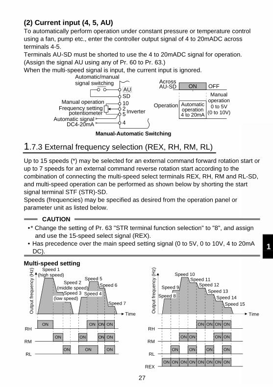
(2) Current input (4, 5, AU)To automatically perform operation under constant pressure or temperature controlusing a fan, pump etc., enter the controller output signal of 4 to 20mADC acrossterminals 4-5.Terminals AU-SD must be shorted to use the 4 to 20mADC signal for operation.(Assign the signal AU using any of Pr. 60 to Pr. 63.)When the multi-speed signal is input, the current input is ignored.
Automatic/manual signal switching
Automatic signalDC4-20mA
AUSD1025
4
Across AU-SD
Inverter
OFFON
OperationManual operation
Frequency setting potentiometer
Automaticoperation4 to 20mA
Manual-Automatic Switching
Manual operation0 to 5V
(0 to 10V)
1.7.3 External frequency selection (REX, RH, RM, RL)
Up to 15 speeds (*) may be selected for an external command forward rotation start orup to 7 speeds for an external command reverse rotation start according to thecombination of connecting the multi-speed select terminals REX, RH, RM and RL-SD,and multi-speed operation can be performed as shown below by shorting the startsignal terminal STF (STR)-SD.Speeds (frequencies) may be specified as desired from the operation panel orparameter unit as listed below.
CAUTION
•* Change the setting of Pr. 63 "STR terminal function selection" to "8", and assignand use the 15-speed select signal (REX).
• Has precedence over the main speed setting signal (0 to 5V, 0 to 10V, 4 to 20mADC).
Multi-speed setting
REX
Speed 1(high speed)
Speed 5
Speed 6
Speed 7
Time
ON ON ON ONRM
ONONONRL
RHON ON ON ON
Ou
tput
freq
uen
cy (
Hz)
(low speed)Speed 3
Speed 2(middle speed)
Speed 4
Time
Speed 9
Speed 10Speed 11
Speed 12Speed 13
Speed 14
Speed 15
ON ON ON ONRH
ON ON ON ONRM
ON ON ON ONRL
ONON ON ON ON ON ON ONREX
Ou
tput
freq
uen
cy (
Hz)
Speed 8
28
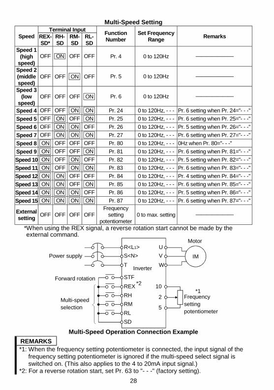
Multi-Speed SettingTerminal Input
Speed REX-SD*
RH-SD
RM-SD
RL-SD
FunctionNumber
Set FrequencyRange
Remarks
Speed 1(high
speed)OFF ON OFF OFF Pr. 4 0 to 120Hz ———————
Speed 2(middlespeed)
OFF OFF ON OFF Pr. 5 0 to 120Hz ———————
Speed 3(low
speed)OFF OFF OFF ON Pr. 6 0 to 120Hz ———————
Speed 4 OFF OFF ON ON Pr. 24 0 to 120Hz, - - - Pr. 6 setting when Pr. 24="- - -"
Speed 5 OFF ON OFF ON Pr. 25 0 to 120Hz, - - - Pr. 6 setting when Pr. 25="- - -"
Speed 6 OFF ON ON OFF Pr. 26 0 to 120Hz, - - - Pr. 5 setting when Pr. 26="- - -"
Speed 7 OFF ON ON ON Pr. 27 0 to 120Hz, - - - Pr. 6 setting when Pr. 27="- - -"
Speed 8 ON OFF OFF OFF Pr. 80 0 to 120Hz, - - - 0Hz when Pr. 80="- - -"
Speed 9 ON OFF OFF ON Pr. 81 0 to 120Hz, - - - Pr. 6 setting when Pr. 81="- - -"
Speed 10 ON OFF ON OFF Pr. 82 0 to 120Hz, - - - Pr. 5 setting when Pr. 82="- - -"
Speed 11 ON OFF ON ON Pr. 83 0 to 120Hz, - - - Pr. 6 setting when Pr. 83="- - -"
Speed 12 ON ON OFF OFF Pr. 84 0 to 120Hz, - - - Pr. 4 setting when Pr. 84="- - -"
Speed 13 ON ON OFF ON Pr. 85 0 to 120Hz, - - - Pr. 6 setting when Pr. 85="- - -"
Speed 14 ON ON ON OFF Pr. 86 0 to 120Hz, - - - Pr. 5 setting when Pr. 86="- - -"
Speed 15 ON ON ON ON Pr. 87 0 to 120Hz, - - - Pr. 6 setting when Pr. 87="- - -"
Externalsetting
OFF OFF OFF OFFFrequency
settingpotentiometer
0 to max. setting ———————
*When using the REX signal, a reverse rotation start cannot be made by theexternal command.
10
2
5
Power supply
Forward rotation
Multi-speed selection
Frequency setting potentiometer
Inverter
R<L1>
S<N>
T
U
V
W
STF
REX
RH
RM
RL
SD
IM
Motor
*2
*1
Multi-Speed Operation Connection Example
REMARKS*1: When the frequency setting potentiometer is connected, the input signal of the
frequency setting potentiometer is ignored if the multi-speed select signal isswitched on. (This also applies to the 4 to 20mA input signal.)
*2: For a reverse rotation start, set Pr. 63 to "- - -" (factory setting).
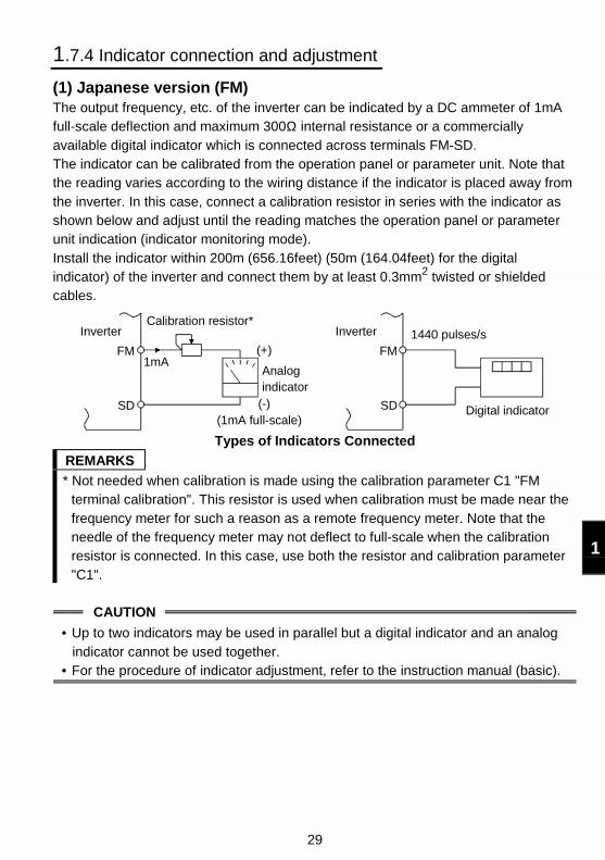
29
1
1.7.4 Indicator connection and adjustment
(1) Japanese version (FM)The output frequency, etc. of the inverter can be indicated by a DC ammeter of 1mAfull-scale deflection and maximum 300Ω internal resistance or a commerciallyavailable digital indicator which is connected across terminals FM-SD.The indicator can be calibrated from the operation panel or parameter unit. Note thatthe reading varies according to the wiring distance if the indicator is placed away fromthe inverter. In this case, connect a calibration resistor in series with the indicator asshown below and adjust until the reading matches the operation panel or parameterunit indication (indicator monitoring mode).Install the indicator within 200m (656.16feet) (50m (164.04feet) for the digitalindicator) of the inverter and connect them by at least 0.3mm2 twisted or shieldedcables.
Digital indicator
1440 pulses/sFM
SD
Inverter
Analog indicator
Calibration resistor*
(+)
(1mA full-scale)
FM
SD
1mA
Inverter
(-)
Types of Indicators Connected
REMARKS
* Not needed when calibration is made using the calibration parameter C1 "FMterminal calibration". This resistor is used when calibration must be made near thefrequency meter for such a reason as a remote frequency meter. Note that theneedle of the frequency meter may not deflect to full-scale when the calibrationresistor is connected. In this case, use both the resistor and calibration parameter"C1".
CAUTION
• Up to two indicators may be used in parallel but a digital indicator and an analogindicator cannot be used together.
• For the procedure of indicator adjustment, refer to the instruction manual (basic).
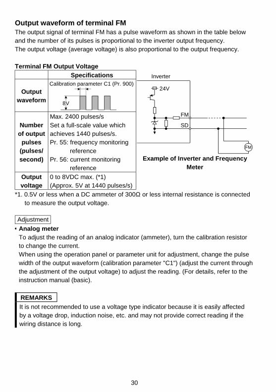
30
Output waveform of terminal FMThe output signal of terminal FM has a pulse waveform as shown in the table belowand the number of its pulses is proportional to the inverter output frequency.The output voltage (average voltage) is also proportional to the output frequency.
Terminal FM Output Voltage
Specifications
Outputwaveform
Calibration parameter C1 (Pr. 900)
8V
Numberof output
pulses(pulses/second)
Max. 2400 pulses/sSet a full-scale value whichachieves 1440 pulses/s.Pr. 55: frequency monitoring
referencePr. 56: current monitoring
reference
Outputvoltage
0 to 8VDC max. (*1)(Approx. 5V at 1440 pulses/s)
Inverter
24V
SD
FM
FM
Example of Inverter and FrequencyMeter
*1. 0.5V or less when a DC ammeter of 300Ω or less internal resistance is connectedto measure the output voltage.
Adjustment Analog meterTo adjust the reading of an analog indicator (ammeter), turn the calibration resistorto change the current.When using the operation panel or parameter unit for adjustment, change the pulsewidth of the output waveform (calibration parameter "C1") (adjust the current throughthe adjustment of the output voltage) to adjust the reading. (For details, refer to theinstruction manual (basic).
REMARKS
It is not recommended to use a voltage type indicator because it is easily affectedby a voltage drop, induction noise, etc. and may not provide correct reading if thewiring distance is long.
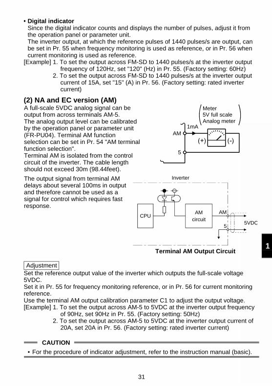
31
1
Digital indicatorSince the digital indicator counts and displays the number of pulses, adjust it fromthe operation panel or parameter unit.The inverter output, at which the reference pulses of 1440 pulses/s are output, canbe set in Pr. 55 when frequency monitoring is used as reference, or in Pr. 56 whencurrent monitoring is used as reference.
[Example] 1. To set the output across FM-SD to 1440 pulses/s at the inverter outputfrequency of 120Hz, set "120" (Hz) in Pr. 55. (Factory setting: 60Hz)
2. To set the output across FM-SD to 1440 pulses/s at the inverter outputcurrent of 15A, set "15" (A) in Pr. 56. (Factory setting: rated invertercurrent)
(2) NA and EC version (AM)A full-scale 5VDC analog signal can beoutput from across terminals AM-5.The analog output level can be calibratedby the operation panel or parameter unit(FR-PU04). Terminal AM functionselection can be set in Pr. 54 "AM terminalfunction selection".Terminal AM is isolated from the controlcircuit of the inverter. The cable lengthshould not exceed 30m (98.44feet).
1mAAM
5
Meter5V full scaleAnalog meter
The output signal from terminal AMdelays about several 100ms in outputand therefore cannot be used as asignal for control which requires fastresponse.
CPUAM
55VDC
Inverter
AMcircuit
Terminal AM Output Circuit
Adjustment Set the reference output value of the inverter which outputs the full-scale voltage5VDC.Set it in Pr. 55 for frequency monitoring reference, or in Pr. 56 for current monitoringreference.Use the terminal AM output calibration parameter C1 to adjust the output voltage.[Example] 1. To set the output across AM-5 to 5VDC at the inverter output frequency
of 90Hz, set 90Hz in Pr. 55. (Factory setting: 50Hz)2. To set the output across AM-5 to 5VDC at the inverter output current of
20A, set 20A in Pr. 56. (Factory setting: rated inverter current)
CAUTION
• For the procedure of indicator adjustment, refer to the instruction manual (basic).
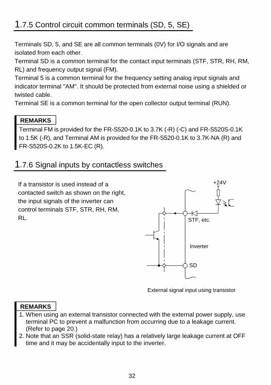
32
1.7.5 Control circuit common terminals (SD, 5, SE)
Terminals SD, 5, and SE are all common terminals (0V) for I/O signals and areisolated from each other.Terminal SD is a common terminal for the contact input terminals (STF, STR, RH, RM,RL) and frequency output signal (FM).Terminal 5 is a common terminal for the frequency setting analog input signals andindicator terminal "AM". It should be protected from external noise using a shielded ortwisted cable.Terminal SE is a common terminal for the open collector output terminal (RUN).
REMARKS
Terminal FM is provided for the FR-S520-0.1K to 3.7K (-R) (-C) and FR-S520S-0.1Kto 1.5K (-R), and Terminal AM is provided for the FR-S520-0.1K to 3.7K-NA (R) andFR-S520S-0.2K to 1.5K-EC (R).
1.7.6 Signal inputs by contactless switches
If a transistor is used instead of acontacted switch as shown on the right,the input signals of the inverter cancontrol terminals STF, STR, RH, RM,RL.
+24V
STF, etc.
SD
Inverter
External signal input using transistor
REMARKS1. When using an external transistor connected with the external power supply, use
terminal PC to prevent a malfunction from occurring due to a leakage current.(Refer to page 20.)
2. Note that an SSR (solid-state relay) has a relatively large leakage current at OFFtime and it may be accidentally input to the inverter.
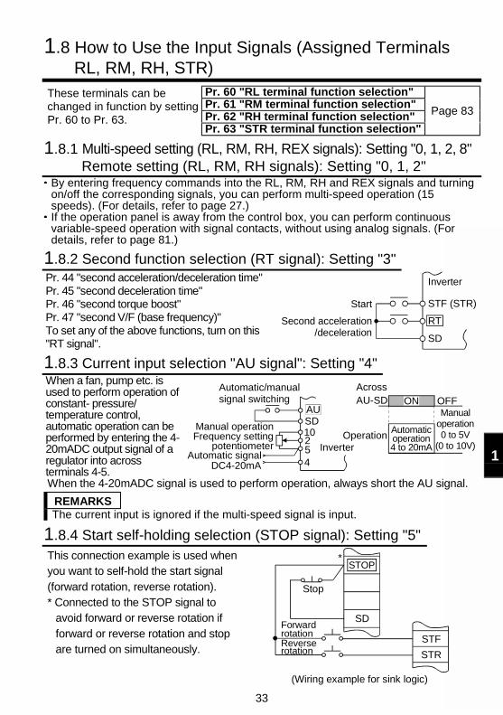
33
1
1.8 How to Use the Input Signals (Assigned TerminalsRL, RM, RH, STR)
Pr. 60 "RL terminal function selection"Pr. 61 "RM terminal function selection"Pr. 62 "RH terminal function selection"
These terminals can bechanged in function by settingPr. 60 to Pr. 63.
Pr. 63 "STR terminal function selection"
Page 83
1.8.1 Multi-speed setting (RL, RM, RH, REX signals): Setting "0, 1, 2, 8"Remote setting (RL, RM, RH signals): Setting "0, 1, 2"
By entering frequency commands into the RL, RM, RH and REX signals and turningon/off the corresponding signals, you can perform multi-speed operation (15speeds). (For details, refer to page 27.)If the operation panel is away from the control box, you can perform continuousvariable-speed operation with signal contacts, without using analog signals. (Fordetails, refer to page 81.)
1.8.2 Second function selection (RT signal): Setting "3"Pr. 44 "second acceleration/deceleration time"Pr. 45 "second deceleration time"Pr. 46 "second torque boost"Pr. 47 "second V/F (base frequency)"To set any of the above functions, turn on this"RT signal".
STF (STR)
RT
SD
Inverter
Start
Second acceleration/deceleration
1.8.3 Current input selection "AU signal": Setting "4"When a fan, pump etc. isused to perform operation ofconstant- pressure/temperature control,automatic operation can beperformed by entering the 4-20mADC output signal of aregulator into acrossterminals 4-5.
OFFAutomatic/manualsignal switching
Manual operation Frequency setting
potentiometerAutomatic signal
DC4-20mA
AUSD10254
AcrossAU-SD
Inverter
ON
OperationAutomaticoperation4 to 20mA
Manual operation0 to 5V
(0 to 10V)
When the 4-20mADC signal is used to perform operation, always short the AU signal.
REMARKSThe current input is ignored if the multi-speed signal is input.
1.8.4 Start self-holding selection (STOP signal): Setting "5"This connection example is used whenyou want to self-hold the start signal(forward rotation, reverse rotation).* Connected to the STOP signal to
avoid forward or reverse rotation ifforward or reverse rotation and stopare turned on simultaneously.
STF
STR
Stop
ForwardrotationReverserotation
(Wiring example for sink logic)
SD
STOP*
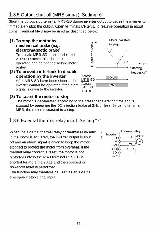
34
1.8.5 Output shut-off (MRS signal): Setting "6"Short the output stop terminal MRS-SD during inverter output to cause the inverter toimmediately stop the output. Open terminals MRS-SD to resume operation in about10ms. Terminal MRS may be used as described below:
(1) To stop the motor bymechanical brake (e.g.electromagnetic brake)Terminals MRS-SD must be shortedwhen the mechanical brake isoperated and be opened before motorrestart.
(2) To provide interlock to disableoperation by the inverterAfter MRS-SD have been shorted, theinverter cannot be operated if the startsignal is given to the inverter.
Out
put f
requ
ency
Motor coasted to stop
0.5Hz
Across STF-SD (STR)
ON
ON
Pr. 13"starting frequency"
AcrossMRS -SD
(3) To coast the motor to stopThe motor is decelerated according to the preset deceleration time and isstopped by operating the DC injection brake at 3Hz or less. By using terminalMRS, the motor is coasted to a stop.
1.8.6 External thermal relay input: Setting "7"
When the external thermal relay or thermal relay builtin the motor is actuated, the inverter output is shutoff and an alarm signal is given to keep the motorstopped to protect the motor from overheat. If thethermal relay contact is reset, the motor is notrestarted unless the reset terminal RES-SD isshorted for more than 0.1s and then opened orpower-on reset is performed.The function may therefore be used as an externalemergency stop signal input.
InverterUVW
OHSD
Thermal relay
Motor
IM
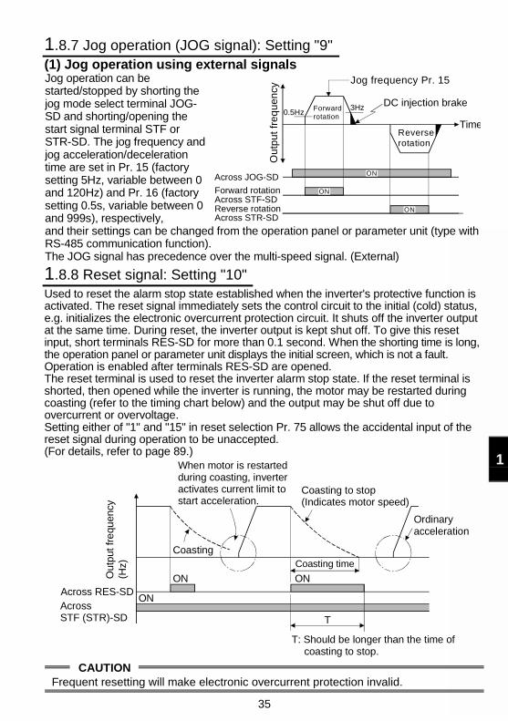
35
1
1.8.7 Jog operation (JOG signal): Setting "9"(1) Jog operation using external signalsJog operation can bestarted/stopped by shorting thejog mode select terminal JOG-SD and shorting/opening thestart signal terminal STF orSTR-SD. The jog frequency andjog acceleration/decelerationtime are set in Pr. 15 (factorysetting 5Hz, variable between 0and 120Hz) and Pr. 16 (factorysetting 0.5s, variable between 0and 999s), respectively,
Ou
tpu
t fr
eq
ue
ncy
Forwardrotation
Jog frequency Pr. 15
DC injection brake
Reverserotation
Across JOG-SD
Forward rotationAcross STF-SDReverse rotationAcross STR-SD
Time0.5Hz
3Hz
ON
ON
ON
and their settings can be changed from the operation panel or parameter unit (type withRS-485 communication function).The JOG signal has precedence over the multi-speed signal. (External)
1.8.8 Reset signal: Setting "10"Used to reset the alarm stop state established when the inverter's protective function isactivated. The reset signal immediately sets the control circuit to the initial (cold) status,e.g. initializes the electronic overcurrent protection circuit. It shuts off the inverter outputat the same time. During reset, the inverter output is kept shut off. To give this resetinput, short terminals RES-SD for more than 0.1 second. When the shorting time is long,the operation panel or parameter unit displays the initial screen, which is not a fault.Operation is enabled after terminals RES-SD are opened.The reset terminal is used to reset the inverter alarm stop state. If the reset terminal isshorted, then opened while the inverter is running, the motor may be restarted duringcoasting (refer to the timing chart below) and the output may be shut off due toovercurrent or overvoltage.Setting either of "1" and "15" in reset selection Pr. 75 allows the accidental input of thereset signal during operation to be unaccepted.(For details, refer to page 89.)
Across RES-SDAcross STF (STR)-SD
ON
ON
Coasting
When motor is restarted during coasting, inverter activates current limit to start acceleration.
Coasting to stop(Indicates motor speed)
Coasting time
ON
T
Ordinary acceleration
T: Should be longer than the time ofcoasting to stop.
Out
put f
requ
ency
(H
z)
CAUTIONFrequent resetting will make electronic overcurrent protection invalid.
36
1.8.9 PID control valid terminal: Setting "14"
To exercise PID control, turn on the X14 signal. When this signal is off, ordinaryinverter operation is performed. For more information, refer to page 96.
♦♦♦♦ Related parameters♦♦♦♦Pr. 88 "PID action selection", Pr. 89 "PID proportional band", Pr. 90 "PID integral time", Pr. 91"PID upper limit", Pr. 92 "PID lower limit", Pr. 93 "PID control set point for PU operation", Pr. 94"PID differential time" (refer to page 96)
1.8.10 PU operation/external operation switching: Setting "16"
You can change the operation mode.With "8" set in Pr. 79 "operation mode selection", turning on the X16 signal shifts theoperation mode to the external operation mode and turning off the X16 signal shifts itto the PU operation mode. For details, refer to page 93.
♦♦♦♦ Related parameters♦♦♦♦Pr. 79 "operation mode selection" (refer to page 93)
1.9 Handling of the RS-485 Connector (Type with RS-485Communication Function)
<RS-485 connector pin layout>View A of the inverter (receptacle side)
8) to 1)
1) SG2) P5S3) RDA4) SDB
5) SDA6) RDB7) SG8) P5S
View A
View A
CAUTION
1. Do not plug the connector to a computer LAN board, fax modem socket,telephone modular connector etc. as they are different in electrical specifications,the inverter may be damaged.
2. Pins 2 and 8 (P5S) are provided for the parameter unit power supply. Do not usethem for any other purpose or when making parallel connection by RS-485communication.
(1) When connecting the parameter unitUse the optional FR-CB2 .
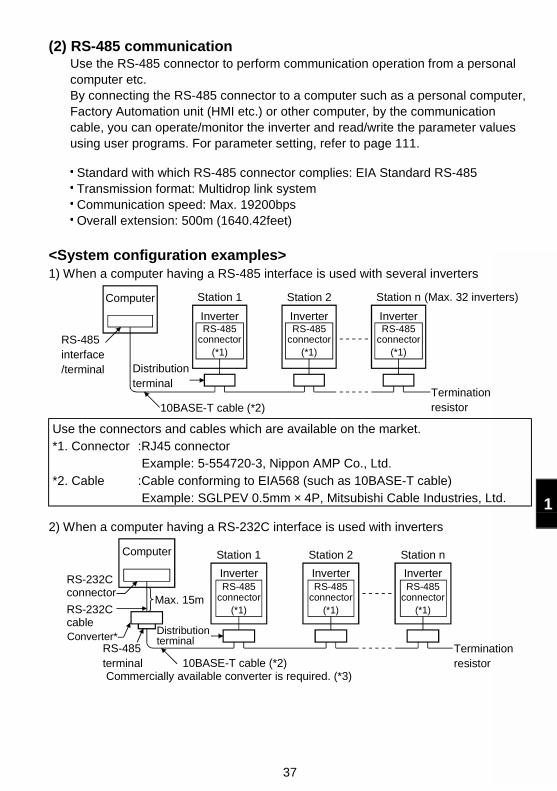
37
1
(2) RS-485 communicationUse the RS-485 connector to perform communication operation from a personalcomputer etc.By connecting the RS-485 connector to a computer such as a personal computer,Factory Automation unit (HMI etc.) or other computer, by the communicationcable, you can operate/monitor the inverter and read/write the parameter valuesusing user programs. For parameter setting, refer to page 111.
Standard with which RS-485 connector complies: EIA Standard RS-485 Transmission format: Multidrop link system Communication speed: Max. 19200bps Overall extension: 500m (1640.42feet)
<System configuration examples>1) When a computer having a RS-485 interface is used with several inverters
Station 1
RS-485 interface/terminal
Computer
RS-485connector
(*1)
RS-485connector
(*1)
RS-485connector
(*1)
10BASE-T cable (*2)
Distributionterminal
Inverter
Station 2
Inverter
Station n
Inverter
Terminationresistor
(Max. 32 inverters)
Use the connectors and cables which are available on the market.*1. Connector :RJ45 connector
Example: 5-554720-3, Nippon AMP Co., Ltd.*2. Cable :Cable conforming to EIA568 (such as 10BASE-T cable)
Example: SGLPEV 0.5mm × 4P, Mitsubishi Cable Industries, Ltd.
2) When a computer having a RS-232C interface is used with inverters
10BASE-T cable (*2)
RS-485connector
(*1)
RS-232Cconnector
RS-232Ccable
Station 1
Inverter
Station 2 Station nComputer
Inverter InverterRS-485
connector(*1)
RS-485connector
(*1)
RS-485terminal
Max. 15m
Converter*Distributionterminal
Terminationresistor
Commercially available converter is required. (*3)
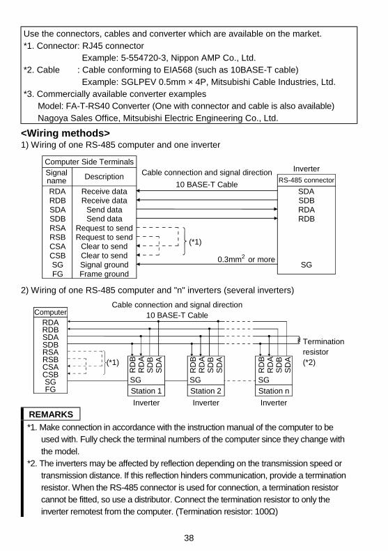
38
Use the connectors, cables and converter which are available on the market.*1. Connector: RJ45 connector
Example: 5-554720-3, Nippon AMP Co., Ltd.*2. Cable : Cable conforming to EIA568 (such as 10BASE-T cable)
Example: SGLPEV 0.5mm × 4P, Mitsubishi Cable Industries, Ltd.*3. Commercially available converter examples
Model: FA-T-RS40 Converter (One with connector and cable is also available)Nagoya Sales Office, Mitsubishi Electric Engineering Co., Ltd.
<Wiring methods>1) Wiring of one RS-485 computer and one inverter
Receive dataReceive data
FG
RS-485 connector
RSB
CSB
RSA
CSA
SG
SDBSDARDBRDA
SG
RDBRDASDBSDA
(*1)
Inverter
0.3mm or more
Computer Side TerminalsSignal name Description
Send data
Request to send
Signal groundFrame ground
Send data
Request to sendClear to sendClear to send
Cable connection and signal direction
10 BASE-T Cable
2
2) Wiring of one RS-485 computer and "n" inverters (several inverters)
SDBSDARDBRDA
FGSG
CSBCSARSBRSA
RD
BR
DA
SD
BS
DA
SG SGSG
RD
BR
DA
SD
BS
DA
RD
BR
DA
SD
BS
DA
Computer
Terminationresistor(*2)
Cable connection and signal direction10 BASE-T Cable
(*1)
Station 1 Station 2 Station n
Inverter Inverter Inverter
REMARKS
*1. Make connection in accordance with the instruction manual of the computer to beused with. Fully check the terminal numbers of the computer since they change withthe model.
*2. The inverters may be affected by reflection depending on the transmission speed ortransmission distance. If this reflection hinders communication, provide a terminationresistor. When the RS-485 connector is used for connection, a termination resistorcannot be fitted, so use a distributor. Connect the termination resistor to only theinverter remotest from the computer. (Termination resistor: 100Ω)
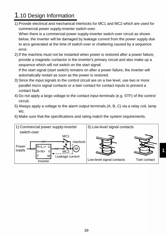
39
1
1.10 Design Information1) Provide electrical and mechanical interlocks for MC1 and MC2 which are used for
commercial power supply-inverter switch-over.When there is a commercial power supply-inverter switch-over circuit as shownbelow, the inverter will be damaged by leakage current from the power supply dueto arcs generated at the time of switch-over or chattering caused by a sequenceerror.
2) If the machine must not be restarted when power is restored after a power failure,provide a magnetic contactor in the inverter's primary circuit and also make up asequence which will not switch on the start signal.If the start signal (start switch) remains on after a power failure, the inverter willautomatically restart as soon as the power is restored.
3) Since the input signals to the control circuit are on a low level, use two or moreparallel micro signal contacts or a twin contact for contact inputs to prevent acontact fault.
4) Do not apply a large voltage to the contact input terminals (e.g. STF) of the controlcircuit.
5) Always apply a voltage to the alarm output terminals (A, B, C) via a relay coil, lampetc.
6) Make sure that the specifications and rating match the system requirements.
1) Commercial power supply-inverterswitch-over
U
V
W
R<L1>
S<N>
T
IMMC2
MC1
Power supply
Inverter
Leakage current
Interlock
3) Low-level signal contacts
Low-level signal contacts Twin contact
40
2
Chapter 1
Chapter 2
Chapter 3
Chapter 4
This chapter explains the "functions" for use of this product. Forsimple variable-speed operation of the inverter, the factory settingsof the parameters may be used as they are. Set the necessaryparameters to meet the load and operational specifications. Referto the instruction manual (basic) for the operation procedures.Always read the instructions before using the functions.
2.1 Function (Parameter) List ....................................................... 412.2 List of Parameters Classified by Purpose of Use.................... 512.3 Explanation of Functions (Parameters)................................... 532.4 Output Terminal Function Parameters.................................... 732.5 Current Detection Function Parameters ................................. 752.6 Display Function Parameters.................................................. 772.7 Restart Operation Parameters ................................................ 792.8 Additional Function Parameters.............................................. 812.9 Terminal Function Selection Parameters................................ 832.10 Operation Selection Function Parameters ............................ 862.11 Auxiliary Function Parameters ............................................ 1042.12 Calibration Parameters ....................................................... 1062.13 Clear Parameters................................................................ 1102.14 Communication Parameters (Only the Type
Having the RS-485 Communication Function) ................... 1112.15 Parameter Unit (FR-PU04) Setting ..................................... 127
CAUTIONAs the contact input terminals RL, RM, RH, STR, open collectoroutput terminal RUN and contact output terminals A, B, C can bechanged in functions by parameter setting, their signal namesused for the corresponding functions are used in this chapter(with the exception of the wiring examples). Note that they are notterminal names.
REMARKSParameter copyUse of the parameter unit (FR-PU04) with the type having theRS-485 communication function allows the parameter values tobe copied to another inverter (only the FR-S500 series).After batch-reading the parameters of the copy source inverter,you can connect the parameter unit to the copy destinationinverter and batch-write the parameters.For the operation procedure, refer to the instruction manual of theparameter unit (FR-PU04).
2. FUNCTIONS
41
2.1 Function (Parameter) List
ParameterIndica-
tionName
SettingRange
MinimumSetting
Increments
FactorySetting
<ECversion>
ReferTo:
Cus-tomerSetting
0 Torque boost 0 to 15% 0.1% 6% 53
1 Maximum frequency 0 to 120Hz 0.1Hz60Hz
<50Hz>54
2 Minimum frequency 0 to 120Hz 0.1Hz 0Hz 54
3 Base frequency 0 to 120Hz 0.1Hz60Hz
<50Hz>54
4 *Multi-speed setting(high speed)
0 to 120Hz 0.1Hz60Hz
<50Hz>56
5 *Multi-speed setting(middle speed)
0 to 120Hz 0.1Hz 30Hz 56
6 *Multi-speed setting(low speed)
0 to 120Hz 0.1Hz 10Hz 56
7 Acceleration time 0 to 999s 0.1s 5s 578 Deceleration time 0 to 999s 0.1s 5s 57
9Electronic thermal O/Lrelay
0 to 50A 0.1ARatedoutputcurrent
59
30 *Extended functiondisplay selection
0, 1 1 0 67
79Operation modeselection
0 to 4, 7, 8 1 0 93
The extended function parameters are made valid by setting "1" in Pr. 30 "extendedfunction display selection". (For full information on the way to set Pr. 30, refer to theinstruction manual (basic).)
Func-tion
Pa-rame-
ter
Indica-tion
Name Setting RangeMinimumSetting
Increments
FactorySetting
ReferTo:
Cus-tomerSetting
10
DC injectionbrakeoperationfrequency
0 to 120Hz 0.1Hz 3Hz 59
11DC injectionbrakeoperation time
0 to 10s 0.1s 0.5s 59
12DC injectionbrake voltage
0 to 15% 0.1% 6% 59
13Startingfrequency
0 to 60Hz 0.1Hz 0.5Hz 60
Sta
ndar
d op
erat
ion
func
tions
14Load patternselection
0: For constant-torqueloads,
1: For variable-torqueloads,
2: For vertical lift loads,3: For vertical lift loads
1 0 61
Pam
met
er L
ist
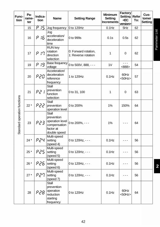
42
2
Func-tion
Pa-rame-
ter
Indica-tion Name Setting Range
MinimumSetting
Increments
FactorySetting
<ECversion>
ReferTo:
Cus-tomerSetting
15 Jog frequency 0 to 120Hz 0.1Hz 5Hz 62
16
Jogacceleration/decelerationtime
0 to 999s 0.1s 0.5s 62
17
RUN keyrotationdirectionselection
0: Forward rotation,1: Reverse rotation
1 0 62
19Base frequencyvoltage
0 to 500V, 888, - - - 1V- - -
<888>54
20
Acceleration/decelerationreferencefrequency
1 to 120Hz 0.1Hz60Hz
<50Hz>57
21
Stallpreventionfunctionselection
0 to 31, 100 1 0 63
22 *Stallpreventionoperation level
0 to 200% 1% 150% 64
23
Stallpreventionoperation levelcompensationfactor atdouble speed
0 to 200%, - - - 1% - - - 64
24 *Multi-speedsetting(speed 4)
0 to 120Hz, - - - 0.1Hz - - - 56
25 *Multi-speedsetting(speed 5)
0 to 120Hz, - - - 0.1Hz - - - 56
26 *Multi-speedsetting(speed 6)
0 to 120Hz, - - - 0.1Hz - - - 56
27 *Multi-speedsetting(speed 7)
0 to 120Hz, - - - 0.1Hz - - - 56
Sta
ndar
d op
erat
ion
func
tions
28
Stallpreventionoperationreductionstartingfrequency
0 to 120Hz 0.1Hz60Hz
<50Hz>64
Pam
met
er L
ist
43
Func-tion
Pa-rame-
ter
Indica-tion
Name Setting RangeMinimumSetting
Increments
FactorySetting
<ECversion>
ReferTo:
Cus-tomerSetting
29Acceleration/decelerationpattern
0: Linear acceleration/deceleration,
1: S-pattern acceleration/deceleration A,
2: S-pattern acceleration/deceleration B
1 0 66
31 Frequencyjump 1A 0 to 120Hz, - - - 0.1Hz - - - 67
32 Frequencyjump 1B 0 to 120Hz, - - - 0.1Hz - - - 67
33 Frequencyjump 2A
0 to 120Hz, - - - 0.1Hz - - - 67
34 Frequencyjump 2B
0 to 120Hz, - - - 0.1Hz - - - 67
35 Frequencyjump 3A
0 to 120Hz, - - - 0.1Hz - - - 67
36 Frequencyjump 3B 0 to 120Hz, - - - 0.1Hz - - - 67
37 Speed display 0, 0.1 to 999 0.1 0 68
38Frequencysetting voltagegain frequency
1 to 120Hz 0.1Hz 60Hz<50Hz> 69
39Frequencysetting currentgain frequency
1 to 120Hz 0.1Hz 60Hz<50Hz> 69
Sta
ndar
d op
erat
ion
func
tions
40
Start-timeground faultdetectionselection
0: Not detected1: Detected 1 0
<1> 73
41Up-to-frequencysensitivity
0 to 100% 1% 10% 73
42Outputfrequencydetection
0 to 120Hz 0.1Hz 6Hz 74
Out
put t
erm
inal
func
tions
43
Outputfrequencydetection forreverserotation
0 to 120Hz, - - - 0.1Hz - - - 74
44
Secondacceleration/decelerationtime
0 to 999s 0.1s 5s 57
45Seconddecelerationtime
0 to 999s, - - - 0.1s - - - 57
46 Second torqueboost 0 to 15%, - - - 0.1% - - - 53
Sec
ond
func
tions
47Second V/F(basefrequency)
0 to 120Hz, - - - 0.1Hz - - - 54
Pam
met
er L
ist
44
2
Func-tion
Pa-rame-
ter
Indica-tion Name Setting Range
MinimumSetting
Increments
FactorySetting
<ECversion>
ReferTo:
Cus-tomerSetting
48 Output currentdetection level 0 to 200% 1% 150% 75
49
Output currentdetectionsignal delaytime
0 to 10s 0.1s 0s 75
50 Zero currentdetection level 0 to 200% 1% 5% 76
Cur
rent
det
ectio
n
51 Zero currentdetection time
0.05 to 1s 0.01s 0.5s 76
52 *Control paneldisplay dataselection
0: Output frequency,1: Output current,100: Set frequency
during stop/outputfrequency duringoperation
1 0 77
53 *
Frequencysettingoperationselection
0: Setting dialfrequency settingmode
1: Setting dialpotentiometer mode
1 0 78
54 *
FM (AM)terminalfunctionselection
0: Output frequencymonitor
1: Output currentmonitor
1 0 77
55 *Frequencymonitoringreference
0 to 120Hz 0.1Hz 60Hz<50Hz>
79
Dis
play
func
tions
56 *Currentmonitoringreference
0 to 50A 0.1ARatedoutputcurrent
79
57 Restartcoasting time 0 to 5s, - - - 0.1s - - - 79
Aut
omat
ic r
esta
rtfu
nctio
ns
58 Restartcushion time 0 to 60s 0.1s 1s 79
Add
ition
al fu
nctio
n
59
Remotesettingfunctionselection
0: Without remotesetting function
1: With remote settingfunctionWith frequencysetting storagefunction
2: With remote settingfunctionWithout frequencysetting storagefunction
1 0 81
Pam
met
er L
ist
45
Func-tion
Pa-rame-
ter
Indica-tion
Name Setting RangeMinimumSetting
Increments
FactorySetting
ReferTo:
Cus-tomerSetting
60RL terminalfunctionselection
1 0 83
61RM terminalfunctionselection
1 1 83
62RH terminalfunctionselection
1 2 83
63STR terminalfunctionselection
0: RL, 1: RM, 2: RH,
3: RT, 4: AU, 5: STOP,
6: MRS, 7: OH,
8: REX, 9: JOG,
10: RES, 14: X14,
16: X16,
- - -: STR (May be
assigned to the STR
terminal only) 1 - - - 83
64RUN terminalfunctionselection
1 0 85
65
A, B, Cterminalfunctionselection
0: RUN, 1: SU, 3: OL,4: FU, 11: RY, 12: Y12,13: Y13, 14: FDN,15: FUP, 16: RL,98: LF, 99: ABC
1 99 85
66 Retry selection
0: OC1 to 3, OV1 to 3,THM, THT, GF,OHT, OLT, PE, OPT
1: OC1 to 3,2: OV1 to 3,3: OC1 to 3, OV1 to 3
1 0 86
67Number ofretries at alarmoccurrence
0: No retry1 to 10:Without alarm outputduring retry operation101 to 110:With alarm outputduring retry operation
1 0 86
68Retry waitingtime
0.1 to 360s 0.1s 1s 86
69Retry countdisplay erase
0: Cumulative counterase
1 0 86
70 *Soft-PWMsetting
0: Soft-PWM invalid,1: Soft-PWM valid
1 1 87
71 Applied motor
0: Thermal characteristicfor standard motor
1: Thermal characteristicfor Mitsubishiconstant-torque motor
1 0 88
72 *PWMfrequencyselection
0 to 15 1 1 87
Ter
min
al fu
nctio
n se
lect
ion
730-5V/0-10Vselection
0: For 0 to 5VDC input1: For 0 to 10VDC input
1 0 88
Pam
met
er L
ist
46
2
Func-tion
Pa-rame-
ter
Indica-tion
Name Setting RangeMinimumSetting
Increments
FactorySetting
ReferTo:
Cus-tomerSetting
74Input filter timeconstant
0: 2-step movingaverage processing
1 to 8:Exponential averagevalue of 2n at thesetting of n
1 1 89
75 *Resetselection/PUstop selection
0: Reset normallyenabled/PU stopkey disabled
1: Enabled at alarmoccurrence only/PUstop key disabled
14: Reset normallyenabled/normallydecelerated to stop
15: Enabled at alarmoccurrenceonly/normallydecelerated to stop
1 14 89
76Cooling fanoperationselection
0: Operation started atpower-on
1: Cooling fan ON/OFFcontrol
1 1 91
77 *Parameterwrite disableselection
0: Write is enabled onlyduring a stop
1: Write disabled(except someparameters)
2: Write duringoperation enabled
1 0 92
Ope
ratio
n se
lect
ion
func
tions
78
Reverserotationpreventionselection
0: Both forward rotationand reverse rotationenabled,
1: Reverse rotationdisabled,
2: Forward rotationdisabled
1 0 93
80 *Multi-speedsetting (speed8)
0 to 120Hz, - - - 0.1Hz - - - 56
81 *Multi-speedsetting (speed9)
0 to 120Hz, - - - 0.1Hz - - - 56
82 *Multi-speedsetting (speed10)
0 to 120Hz, - - - 0.1Hz - - - 56
Mul
ti-sp
eed
oper
atio
n fu
nctio
n
83 *Multi-speedsetting (speed11)
0 to 120Hz, - - - 0.1Hz - - - 56
Pam
met
er L
ist
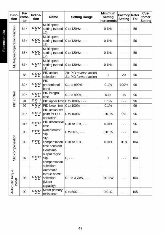
47
Func-tion
Pa-rame-
ter
Indica-tion
Name Setting RangeMinimumSetting
Increments
FactorySetting
ReferTo:
Cus-tomer
Setting
84 *Multi-speedsetting (speed12)
0 to 120Hz, - - - 0.1Hz - - - 56
85 *Multi-speedsetting (speed13)
0 to 120Hz, - - - 0.1Hz - - - 56
86 *Multi-speedsetting (speed14)
0 to 120Hz, - - - 0.1Hz - - - 56
Mul
ti-sp
eed
oper
atio
n fu
nctio
n
87 *Multi-speedsetting (speed15)
0 to 120Hz, - - - 0.1Hz - - - 56
88PID actionselection
20: PID reverse action,21: PID forward action
1 20 96
89 *PIDproportionalband
0.1 to 999%, - - - 0.1% 100% 96
90 *PID integraltime
0.1 to 999s, - - - 0.1s 1s 96
91 PID upper limit 0 to 100%, - - - 0.1% - - - 9692 PID lower limit 0 to 100%, - - - 0.1% - - - 96
93 *PID action setpoint for PUoperation
0 to 100% 0.01% 0% 96
PID
con
trol
94 *PID differentialtime
0.01 to 10s, - - - 0.01s - - - 96
95Rated motorslip
0 to 50%, - - - 0.01% - - - 104
96Slipcompensationtime constant
0.01 to 10s 0.01s 0.5s 104
Slip
com
pens
atio
n
97
Constant-output regionslipcompensationselection
0, - - - 1 - - - 104
98
Automatictorque boostselection(Motorcapacity)
0.1 to 3.7kW, - - - 0.01kW - - - 104
Aut
omat
ic to
rque
boos
t
99Motor primaryresistance
0 to 50Ω, - - - 0.01Ω - - - 105
Pam
met
er L
ist
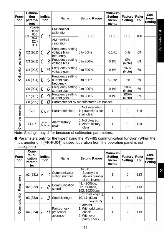
48
2
Func-tion
Calibra-tion
parame-ters
Indica-tion Name Setting Range
MinimumSettingIncre-ments
FactorySetting
ReferTo:
Cus-tomerSetting
<Japa-nese>900
FM terminalcalibration
C1<NA,EC>901
AM terminalcalibration
106
C2 (902)Frequency settingvoltage biasfrequency
0 to 60Hz 0.1Hz 0Hz 69
C3 (902) Frequency settingvoltage bias 0 to 300% 0.1% 0%
(Note) 69
C4 (903) Frequency settingvoltage gain 0 to 300% 0.1% 96%
(Note) 69
C5 (904)Frequency settingcurrent biasfrequency
0 to 60Hz 0.1Hz 0Hz 69
C6 (904) Frequency settingcurrent bias 0 to 300% 0.1% 20%
(Note) 69
C7 (905) Frequency settingcurrent gain 0 to 300% 0.1% 100%
(Note) 69
Cal
ibra
tion
para
met
ers
C8 (269) Parameter set by manufacturer. Do not set.
CLr Parameter clear0: Not executed1: parameter clear2: all clear
1 0 110
Cle
ar p
aram
eter
s
ECL * Alarm historyclear
0: Not cleared,1: Alarm history
clear1 0 110
Note: Settings may differ because of calibration parameters.
Parameters only for the type having the RS-485 communication function (When theparameter unit (FR-PU04) is used, operation from the operation panel is notaccepted.)
Func-tion
Com-muni-cation
Parame-ter
Indica-tion Name Setting Range
MinimumSettingIncre-ments
FactorySetting
ReferTo:
Cus-tomerSetting
n1 (331) Communicationstation number
0 to 31:Specify thestation numberof the inverter.
1 0 113
n2 (332) Communicationspeed
48: 4800bps,96: 9600bps,192: 19200bps
1 192 113
n3 (333) Stop bit length0, 1: (Data length 8),10, 11: (Data
length 7)1 1 113
Com
mun
icat
ion
Par
amet
ers
n4 (334)Parity checkpresence/absence
0: Absent,1: With odd parity
check,2: With even
parity check
1 2 113
Pam
met
er L
ist
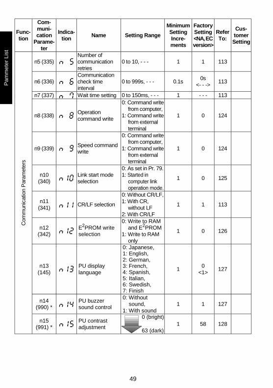
49
Func-tion
Com-muni-cation
Parame-ter
Indica-tion
Name Setting Range
MinimumSettingIncre-ments
FactorySetting<NA, ECversion>
ReferTo:
Cus-tomerSetting
n5 (335)Number ofcommunicationretries
0 to 10, - - - 1 1 113
n6 (336)Communicationcheck timeinterval
0 to 999s, - - - 0.1s0s
<- - ->113
n7 (337) Wait time setting 0 to 150ms, - - - 1 - - - 113
n8 (338)Operationcommand write
0: Command writefrom computer,
1: Command writefrom externalterminal
1 0 124
n9 (339)Speed commandwrite
0: Command writefrom computer,
1: Command writefrom externalterminal
1 0 124
n10(340)
Link start modeselection
0: As set in Pr. 79.1: Started in
computer linkoperation mode.
1 0 125
n11(341)
CR/LF selection
0: Without CR/LF,1: With CR,
without LF2: With CR/LF
1 1 113
n12(342)
E2PROM writeselection
0: Write to RAMand E2PROM
1: Write to RAMonly
1 0 126
n13(145)
PU displaylanguage
0: Japanese,1: English,2: German,3: French,4: Spanish,5: Italian,6: Swedish,7: Finish
10
<1>127
n14(990) *
PU buzzersound control
0: Withoutsound,
1: With sound1 1 127
Com
mun
icat
ion
Par
amet
ers
n15(991) *
PU contrastadjustment
0 (bright)
63 (dark)1 58 128
Pam
met
er L
ist
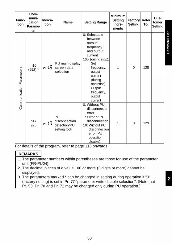
50
2
Func-tion
Com-muni-cation
Parame-ter
Indica-tion
Name Setting Range
MinimumSettingIncre-ments
FactorySetting
ReferTo:
Cus-tomerSetting
n16(992) *
PU main displayscreen dataselection
0: Selectablebetweenoutputfrequencyand outputcurrent
100: (during stop):Setfrequency,outputcurrent(duringoperation):Outputfrequency,outputcurrent
1 0 128
Com
mun
icat
ion
Par
amet
ers
n17(993)
PUdisconnectiondetection/PUsetting lock
0: Without PUdisconnectionerror,
1: Error at PUdisconnection,
10: Without PUdisconnectionerror (PUoperationdisable)
1 0 129
For details of the program, refer to page 113 onwards.
REMARKS1. The parameter numbers within parentheses are those for use of the parameter
unit (FR-PU04).2. The decimal places of a value 100 or more (3 digits or more) cannot be
displayed.3. The parameters marked * can be changed in setting during operation if "0"
(factory setting) is set in Pr. 77 "parameter write disable selection". (Note thatPr. 53, Pr. 70 and Pr. 72 may be changed only during PU operation.)
Pam
met
er L
ist
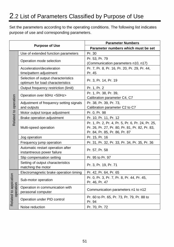
51
2.2 List of Parameters Classified by Purpose of Use
Set the parameters according to the operating conditions. The following list indicatespurpose of use and corresponding parameters.
Parameter NumbersPurpose of Use
Parameter numbers which must be set
Use of extended function parameters Pr. 30
Operation mode selectionPr. 53, Pr. 79(Communication parameters n10, n17)
Acceleration/decelerationtime/pattern adjustment
Pr. 7, Pr. 8, Pr. 16, Pr. 20, Pr. 29, Pr. 44,Pr. 45
Selection of output characteristicsoptimum for load characteristics
Pr. 3, Pr. 14, Pr. 19
Output frequency restriction (limit) Pr. 1, Pr. 2
Operation over 60Hz <50Hz>Pr. 1, Pr. 38, Pr. 39,Calibration parameter C4, C7
Adjustment of frequency setting signalsand outputs
Pr. 38, Pr. 39, Pr. 73,Calibration parameter C2 to C7
Motor output torque adjustment Pr. 0, Pr. 98
Brake operation adjustment Pr. 10, Pr. 11, Pr. 12
Multi-speed operationPr. 1, Pr. 2, Pr. 4, Pr. 5, Pr. 6, Pr. 24, Pr. 25,Pr. 26, Pr. 27, Pr. 80, Pr. 81, Pr. 82, Pr. 83,Pr. 84, Pr. 85, Pr. 86, Pr. 87
Jog operation Pr. 15, Pr. 16
Frequency jump operation Pr. 31, Pr. 32, Pr. 33, Pr. 34, Pr. 35, Pr. 36
Automatic restart operation afterinstantneous power failure
Pr. 57, Pr. 58
Slip compensation setting Pr. 95 to Pr. 97
Rel
ated
to
oper
atio
n
Setting of output characteristicsmatching the motor
Pr. 3, Pr. 19, Pr. 71
Electromagnetic brake operation timing Pr. 42, Pr. 64, Pr. 65
Sub-motor operationPr. 0, Pr. 3, Pr. 7, Pr. 8, Pr. 44, Pr. 45,Pr. 46, Pr. 47
Operation in communication withperasonal computer
Communication parameters n1 to n12
Operation under PID controlPr. 60 to Pr. 65, Pr. 73, Pr. 79, Pr. 88 toPr. 94
Rel
ated
to
appi
catio
nop
erat
ion
Noise reduction Pr. 70, Pr. 72
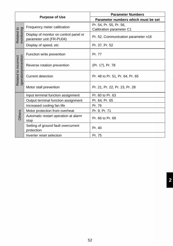
52
2
Parameter NumbersPurpose of Use
Parameter numbers which must be set
Frequency meter calibrationPr. 54, Pr. 55, Pr. 56,Calibration parameter C1
Display of monitor on control panel orparameter unit (FR-PU04)
Pr. 52, Communication parameter n16
Rel
ated
to
mon
itori
ng
Display of speed, etc Pr. 37, Pr. 52
Function write prevention Pr. 77
Reverse rotation prevention (Pr. 17), Pr. 78
Current detection Pr. 48 to Pr. 51, Pr. 64, Pr. 65
Rel
ated
to
inco
rrec
t o
pera
tionp
reve
ntio
n
Motor stall prevention Pr. 21, Pr. 22, Pr. 23, Pr. 28
Input terminal function assignment Pr. 60 to Pr. 63
Output terminal function assignment Pr. 64, Pr. 65
Increased cooling fan life Pr. 76
Motor protection from overheat Pr. 9, Pr. 71
Automatic restart operation at alarmstop
Pr. 66 to Pr. 69
Setting of ground fault overcurrentprotection
Pr. 40
Oth
ers
Inverter reset selection Pr. 75
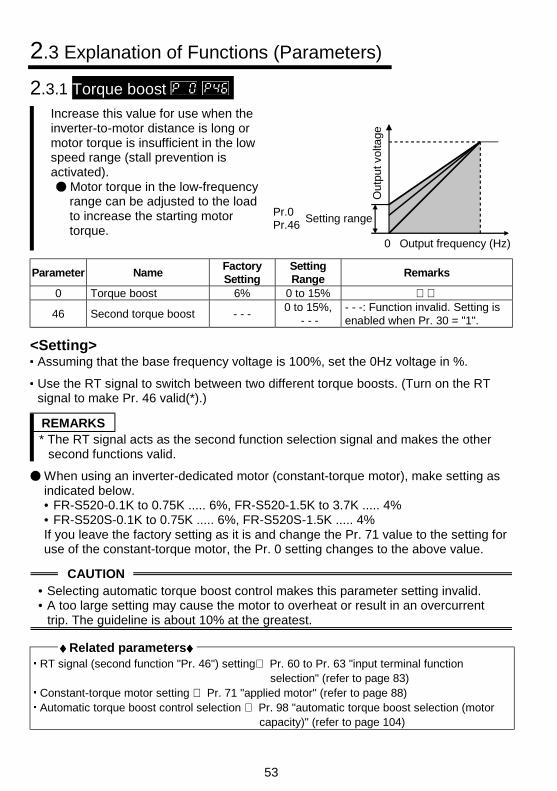
53
2.3 Explanation of Functions (Parameters)
2.3.1 Torque boost Increase this value for use when theinverter-to-motor distance is long ormotor torque is insufficient in the lowspeed range (stall prevention isactivated).
Motor torque in the low-frequencyrange can be adjusted to the loadto increase the starting motortorque.
Out
put v
olta
ge
Pr.0Pr.46
Setting range
0 Output frequency (Hz)
Parameter NameFactorySetting
SettingRange
Remarks
0 Torque boost 6% 0 to 15%
46 Second torque boost - - -0 to 15%,
- - -- - -: Function invalid. Setting isenabled when Pr. 30 = "1".
<Setting>Assuming that the base frequency voltage is 100%, set the 0Hz voltage in %.
Use the RT signal to switch between two different torque boosts. (Turn on the RTsignal to make Pr. 46 valid(*).)
REMARKS* The RT signal acts as the second function selection signal and makes the other
second functions valid.
When using an inverter-dedicated motor (constant-torque motor), make setting asindicated below.• FR-S520-0.1K to 0.75K ..... 6%, FR-S520-1.5K to 3.7K ..... 4%• FR-S520S-0.1K to 0.75K ..... 6%, FR-S520S-1.5K ..... 4%If you leave the factory setting as it is and change the Pr. 71 value to the setting foruse of the constant-torque motor, the Pr. 0 setting changes to the above value.
CAUTION• Selecting automatic torque boost control makes this parameter setting invalid.• A too large setting may cause the motor to overheat or result in an overcurrent
trip. The guideline is about 10% at the greatest.
♦♦♦♦ Related parameters♦♦♦♦ RT signal (second function "Pr. 46") setting⇒ Pr. 60 to Pr. 63 "input terminal function
selection" (refer to page 83) Constant-torque motor setting ⇒ Pr. 71 "applied motor" (refer to page 88) Automatic torque boost control selection ⇒ Pr. 98 "automatic torque boost selection (motor
capacity)" (refer to page 104)
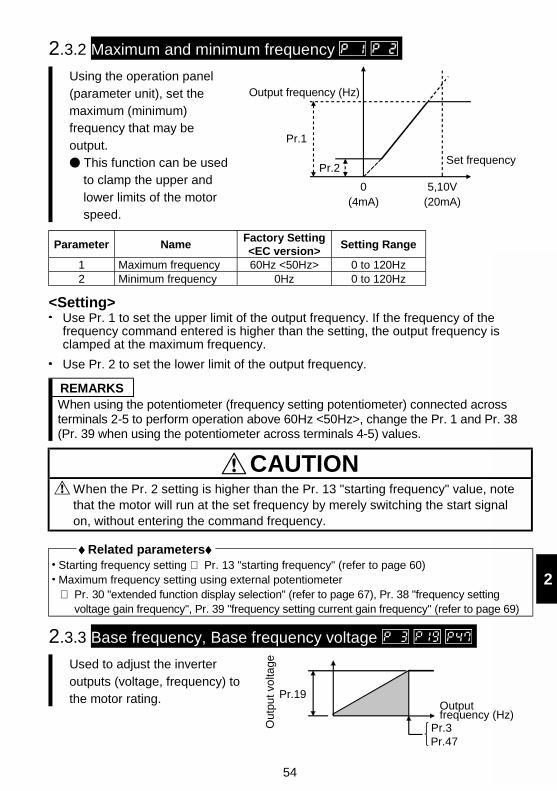
54
2
2.3.2 Maximum and minimum frequency
Using the operation panel(parameter unit), set themaximum (minimum)frequency that may beoutput.
This function can be usedto clamp the upper andlower limits of the motorspeed.
Output frequency (Hz)
Pr.1
Pr.2Set frequency
5,10V(20mA)
0(4mA)
Parameter NameFactory Setting<EC version>
Setting Range
1 Maximum frequency 60Hz <50Hz> 0 to 120Hz2 Minimum frequency 0Hz 0 to 120Hz
<Setting>Use Pr. 1 to set the upper limit of the output frequency. If the frequency of thefrequency command entered is higher than the setting, the output frequency isclamped at the maximum frequency.
Use Pr. 2 to set the lower limit of the output frequency.
REMARKSWhen using the potentiometer (frequency setting potentiometer) connected acrossterminals 2-5 to perform operation above 60Hz <50Hz>, change the Pr. 1 and Pr. 38(Pr. 39 when using the potentiometer across terminals 4-5) values.
CAUTION When the Pr. 2 setting is higher than the Pr. 13 "starting frequency" value, notethat the motor will run at the set frequency by merely switching the start signalon, without entering the command frequency.
♦♦♦♦ Related parameters♦♦♦♦ Starting frequency setting ⇒ Pr. 13 "starting frequency" (refer to page 60) Maximum frequency setting using external potentiometer⇒ Pr. 30 "extended function display selection" (refer to page 67), Pr. 38 "frequency setting
voltage gain frequency", Pr. 39 "frequency setting current gain frequency" (refer to page 69)
2.3.3 Base frequency, Base frequency voltage
Used to adjust the inverteroutputs (voltage, frequency) tothe motor rating. Pr.19
Out
put v
olta
ge
Outputfrequency (Hz)
Pr.3 Pr.47
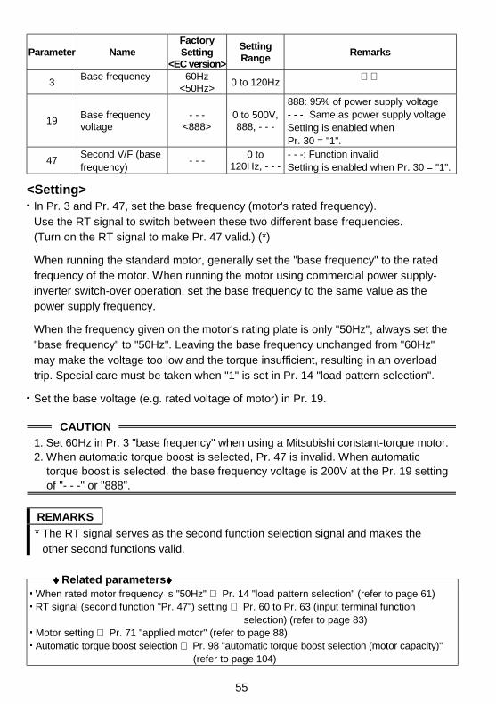
55
Parameter NameFactorySetting
<EC version>
SettingRange
Remarks
3Base frequency 60Hz
<50Hz>0 to 120Hz
19Base frequencyvoltage
- - -<888>
0 to 500V,888, - - -
888: 95% of power supply voltage- - -: Same as power supply voltageSetting is enabled whenPr. 30 = "1".
47Second V/F (basefrequency)
- - -0 to
120Hz, - - -- - -: Function invalidSetting is enabled when Pr. 30 = "1".
<Setting>In Pr. 3 and Pr. 47, set the base frequency (motor's rated frequency).Use the RT signal to switch between these two different base frequencies.(Turn on the RT signal to make Pr. 47 valid.) (*)
When running the standard motor, generally set the "base frequency" to the ratedfrequency of the motor. When running the motor using commercial power supply-inverter switch-over operation, set the base frequency to the same value as thepower supply frequency.
When the frequency given on the motor's rating plate is only "50Hz", always set the"base frequency" to "50Hz". Leaving the base frequency unchanged from "60Hz"may make the voltage too low and the torque insufficient, resulting in an overloadtrip. Special care must be taken when "1" is set in Pr. 14 "load pattern selection".
Set the base voltage (e.g. rated voltage of motor) in Pr. 19.
CAUTION
1. Set 60Hz in Pr. 3 "base frequency" when using a Mitsubishi constant-torque motor.2. When automatic torque boost is selected, Pr. 47 is invalid. When automatic
torque boost is selected, the base frequency voltage is 200V at the Pr. 19 settingof "- - -" or "888".
REMARKS
* The RT signal serves as the second function selection signal and makes theother second functions valid.
♦♦♦♦ Related parameters♦♦♦♦ When rated motor frequency is "50Hz" ⇒ Pr. 14 "load pattern selection" (refer to page 61) RT signal (second function "Pr. 47") setting ⇒ Pr. 60 to Pr. 63 (input terminal function
selection) (refer to page 83) Motor setting ⇒ Pr. 71 "applied motor" (refer to page 88) Automatic torque boost selection ⇒ Pr. 98 "automatic torque boost selection (motor capacity)"
(refer to page 104)
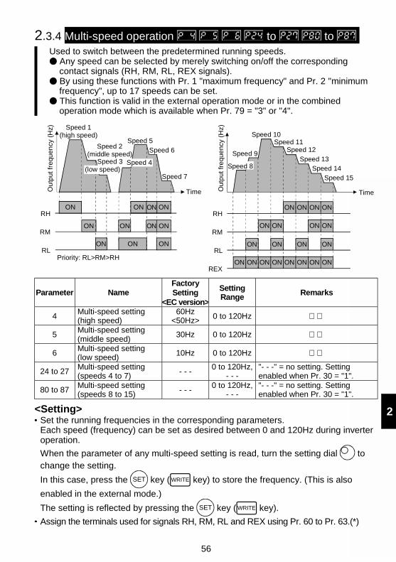
56
2
2.3.4 Multi-speed operation to to Used to switch between the predetermined running speeds.
Any speed can be selected by merely switching on/off the correspondingcontact signals (RH, RM, RL, REX signals). By using these functions with Pr. 1 "maximum frequency" and Pr. 2 "minimumfrequency", up to 17 speeds can be set. This function is valid in the external operation mode or in the combinedoperation mode which is available when Pr. 79 = "3" or "4".
REX
Speed 1(high speed)
Speed 5
Speed 6
Speed 7
Time
ON ON ONONRM
ONONONRL
RHON ON ON ON
Ou
tput
freq
uen
cy (
Hz)
(low speed)Speed 3
Speed 2(middle speed)
Speed 4
Priority: RL>RM>RH
Time
Speed 9
Speed 10Speed 11
Speed 12
Speed 13Speed 14
Speed 15
ON ON ON ONRH
ON ON ON ONRM
ON ON ON ONRL
ONON ON ON ON ON ON ONREX
Out
pu
t fre
que
ncy
(Hz)
Speed 8
Parameter NameFactorySetting
<EC version>
SettingRange
Remarks
4Multi-speed setting(high speed)
60Hz<50Hz> 0 to 120Hz
5Multi-speed setting(middle speed)
30Hz 0 to 120Hz
6Multi-speed setting(low speed) 10Hz 0 to 120Hz
24 to 27Multi-speed setting(speeds 4 to 7)
- - -0 to 120Hz,
- - -"- - -" = no setting. Settingenabled when Pr. 30 = "1".
80 to 87Multi-speed setting(speeds 8 to 15) - - -
0 to 120Hz,- - -
"- - -" = no setting. Settingenabled when Pr. 30 = "1".
<Setting>Set the running frequencies in the corresponding parameters.Each speed (frequency) can be set as desired between 0 and 120Hz during inverteroperation.
When the parameter of any multi-speed setting is read, turn the setting dial tochange the setting.
In this case, press the SET key ( WRITE key) to store the frequency. (This is also
enabled in the external mode.)
The setting is reflected by pressing the SET key ( WRITE key).
Assign the terminals used for signals RH, RM, RL and REX using Pr. 60 to Pr. 63.(*)
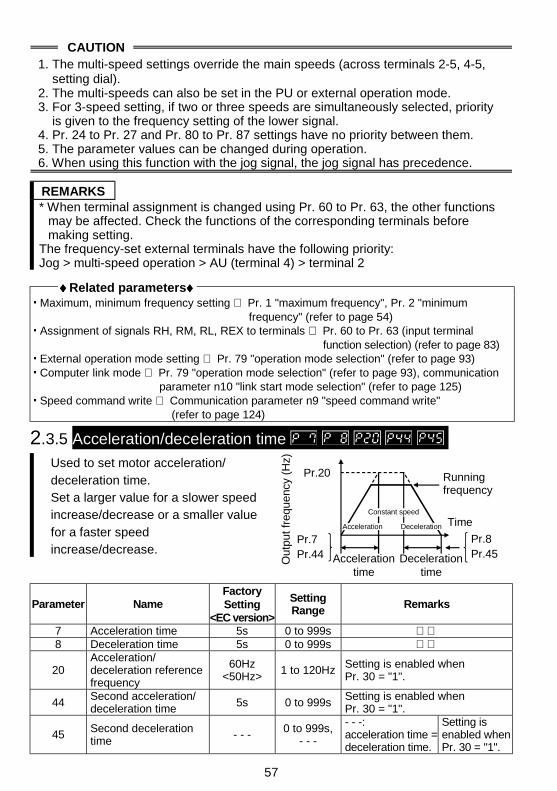
57
CAUTION1. The multi-speed settings override the main speeds (across terminals 2-5, 4-5,
setting dial).2. The multi-speeds can also be set in the PU or external operation mode.3. For 3-speed setting, if two or three speeds are simultaneously selected, priority
is given to the frequency setting of the lower signal.4. Pr. 24 to Pr. 27 and Pr. 80 to Pr. 87 settings have no priority between them.5. The parameter values can be changed during operation.6. When using this function with the jog signal, the jog signal has precedence.
REMARKS* When terminal assignment is changed using Pr. 60 to Pr. 63, the other functions
may be affected. Check the functions of the corresponding terminals beforemaking setting.
The frequency-set external terminals have the following priority:Jog > multi-speed operation > AU (terminal 4) > terminal 2
♦♦♦♦ Related parameters♦♦♦♦ Maximum, minimum frequency setting ⇒ Pr. 1 "maximum frequency", Pr. 2 "minimum
frequency" (refer to page 54) Assignment of signals RH, RM, RL, REX to terminals ⇒ Pr. 60 to Pr. 63 (input terminal
function selection) (refer to page 83) External operation mode setting ⇒ Pr. 79 "operation mode selection" (refer to page 93) Computer link mode ⇒ Pr. 79 "operation mode selection" (refer to page 93), communication
parameter n10 "link start mode selection" (refer to page 125) Speed command write ⇒ Communication parameter n9 "speed command write"
(refer to page 124)
2.3.5 Acceleration/deceleration time Used to set motor acceleration/deceleration time.Set a larger value for a slower speedincrease/decrease or a smaller valuefor a faster speedincrease/decrease.
Runningfrequency
Accelerationtime
Decelerationtime
Time
Pr.20
Out
put f
requ
ency
(H
z)
Pr.7Pr.44
Pr.8Pr.45
Acceleration Deceleration
Constant speed
Parameter NameFactorySetting
<EC version>
SettingRange
Remarks
7 Acceleration time 5s 0 to 999s 8 Deceleration time 5s 0 to 999s
20Acceleration/deceleration referencefrequency
60Hz<50Hz>
1 to 120Hz Setting is enabled whenPr. 30 = "1".
44Second acceleration/deceleration time 5s 0 to 999s
Setting is enabled whenPr. 30 = "1".
45 Second decelerationtime
- - - 0 to 999s,- - -
- - -:acceleration time =deceleration time.
Setting isenabled whenPr. 30 = "1".
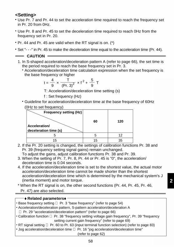
58
2
<Setting>Use Pr. 7 and Pr. 44 to set the acceleration time required to reach the frequency setin Pr. 20 from 0Hz.
Use Pr. 8 and Pr. 45 to set the deceleration time required to reach 0Hz from thefrequency set in Pr. 20.
Pr. 44 and Pr. 45 are valid when the RT signal is on. (*)
Set "- - -" in Pr. 45 to make the deceleration time equal to the acceleration time (Pr. 44).
CAUTION
1. In S-shaped acceleration/deceleration pattern A (refer to page 66), the set time isthe period required to reach the base frequency set in Pr. 3.
Acceleration/deceleration time calculation expression when the set frequency isthe base frequency or higher
4 T 5t =
9 ×
(Pr. 3)2 × f 2 +
9 T
T: Acceleration/deceleration time setting (s)f : Set frequency (Hz)
Guideline for acceleration/deceleration time at the base frequency of 60Hz(0Hz to set frequency)
Frequency setting (Hz)
Acceleration/deceleration time (s)
60 120
5 5 12
15 15 35
2. If the Pr. 20 setting is changed, the settings of calibration functions Pr. 38 andPr. 39 (frequency setting signal gains) remain unchanged.To adjust the gains, adjust calibration functions Pr. 38 and Pr. 39.
3. When the setting of Pr. 7, Pr. 8, Pr. 44 or Pr. 45 is "0", the acceleration/deceleration time is 0.04 seconds.
4. If the acceleration/deceleration time is set to the shortest value, the actual motoracceleration/deceleration time cannot be made shorter than the shortestacceleration/deceleration time which is determined by the mechanical system's J(inertia moment) and motor torque.
* When the RT signal is on, the other second functions (Pr. 44, Pr. 45, Pr. 46,Pr. 47) are also selected.
♦♦♦♦ Related parameters♦♦♦♦ Base frequency setting ⇒ Pr. 3 "base frequency" (refer to page 54) Acceleration/deceleration pattern, S-pattern acceleration/deceleration A⇒ Pr. 29 "acceleration/deceleration pattern" (refer to page 66)
Calibration function ⇒ Pr. 38 "frequency setting voltage gain frequency", Pr. 39 "frequencysetting current gain frequency" (refer to page 69)
RT signal setting ⇒ Pr. 60 to Pr. 63 (input terminal function selection) (refer to page 83) Jog acceleration/deceleration time ⇒ Pr. 16 "jog acceleration/deceleration time"
(refer to page 62)
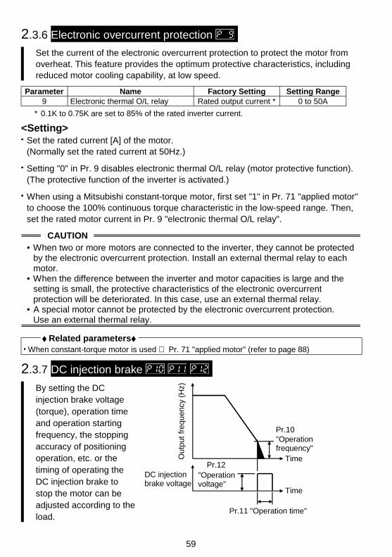
59
2.3.6 Electronic overcurrent protection
Set the current of the electronic overcurrent protection to protect the motor fromoverheat. This feature provides the optimum protective characteristics, includingreduced motor cooling capability, at low speed.
Parameter Name Factory Setting Setting Range9 Electronic thermal O/L relay Rated output current * 0 to 50A
* 0.1K to 0.75K are set to 85% of the rated inverter current.
<Setting>Set the rated current [A] of the motor.(Normally set the rated current at 50Hz.)
Setting "0" in Pr. 9 disables electronic thermal O/L relay (motor protective function).(The protective function of the inverter is activated.)
When using a Mitsubishi constant-torque motor, first set "1" in Pr. 71 "applied motor"to choose the 100% continuous torque characteristic in the low-speed range. Then,set the rated motor current in Pr. 9 "electronic thermal O/L relay".
CAUTION• When two or more motors are connected to the inverter, they cannot be protected
by the electronic overcurrent protection. Install an external thermal relay to eachmotor.
• When the difference between the inverter and motor capacities is large and thesetting is small, the protective characteristics of the electronic overcurrentprotection will be deteriorated. In this case, use an external thermal relay.
• A special motor cannot be protected by the electronic overcurrent protection.Use an external thermal relay.
♦♦♦♦ Related parameters♦♦♦♦ When constant-torque motor is used ⇒ Pr. 71 "applied motor" (refer to page 88)
2.3.7 DC injection brake
By setting the DCinjection brake voltage(torque), operation timeand operation startingfrequency, the stoppingaccuracy of positioningoperation, etc. or thetiming of operating theDC injection brake tostop the motor can beadjusted according to theload.
Ou
tput
fre
qu
ency
(H
z)
Time
Time
DC injectionbrake voltage
"Operationfrequency"
Pr.10
Pr.12"Operationvoltage"
Pr.11 "Operation time"
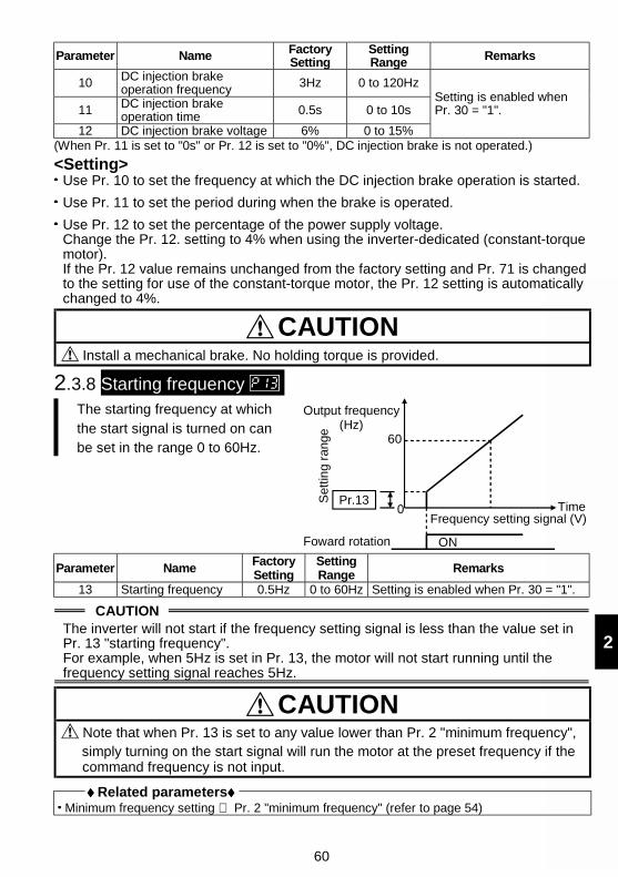
60
2
Parameter Name FactorySetting
SettingRange Remarks
10 DC injection brakeoperation frequency 3Hz 0 to 120Hz
11 DC injection brakeoperation time 0.5s 0 to 10s
12 DC injection brake voltage 6% 0 to 15%
Setting is enabled whenPr. 30 = "1".
(When Pr. 11 is set to "0s" or Pr. 12 is set to "0%", DC injection brake is not operated.)
<Setting>Use Pr. 10 to set the frequency at which the DC injection brake operation is started.
Use Pr. 11 to set the period during when the brake is operated.
Use Pr. 12 to set the percentage of the power supply voltage.Change the Pr. 12. setting to 4% when using the inverter-dedicated (constant-torquemotor).If the Pr. 12 value remains unchanged from the factory setting and Pr. 71 is changedto the setting for use of the constant-torque motor, the Pr. 12 setting is automaticallychanged to 4%.
CAUTION Install a mechanical brake. No holding torque is provided.
2.3.8 Starting frequency The starting frequency at whichthe start signal is turned on canbe set in the range 0 to 60Hz.
Output frequency(Hz)
60
Pr.13
Frequency setting signal (V)
Set
ting
rang
e
Foward rotation ON
0 Time
Parameter NameFactorySetting
SettingRange Remarks
13 Starting frequency 0.5Hz 0 to 60Hz Setting is enabled when Pr. 30 = "1".
CAUTIONThe inverter will not start if the frequency setting signal is less than the value set inPr. 13 "starting frequency".For example, when 5Hz is set in Pr. 13, the motor will not start running until thefrequency setting signal reaches 5Hz.
CAUTION Note that when Pr. 13 is set to any value lower than Pr. 2 "minimum frequency",simply turning on the start signal will run the motor at the preset frequency if thecommand frequency is not input.
♦♦♦♦ Related parameters♦♦♦♦ Minimum frequency setting ⇒ Pr. 2 "minimum frequency" (refer to page 54)
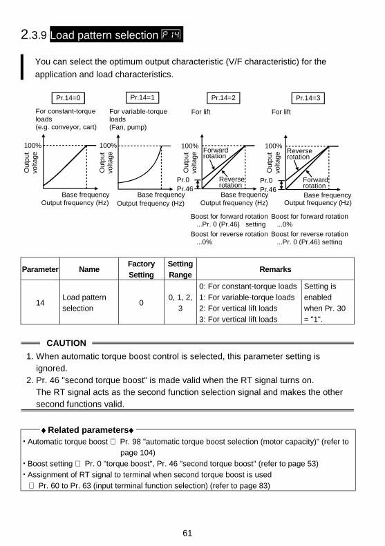
61
2.3.9 Load pattern selection
You can select the optimum output characteristic (V/F characteristic) for the
application and load characteristics.
Forwardrotation
Reverserotation
For constant-torque loads(e.g. conveyor, cart)
100%
Ou
tput
vo
ltage
Base frequencyOutput frequency (Hz)
Pr.14=0
For variable-torque loads(Fan, pump)
100%
Base frequencyOutput frequency (Hz)
Pr.14=1
100%
Base frequencyOutput frequency (Hz)
Forwardrotation
Pr.14=2
Pr.0Pr.46
Pr.14=3
100%
Base frequencyOutput frequency (Hz)
Pr.0Pr.46
For lift
Ou
tput
vo
ltage
Ou
tput
vo
ltage
Ou
tput
vo
ltage
For lift
Reverserotation
Boost for forward rotation ...Pr. 0 (Pr.46) setting
Boost for forward rotation ...0%
Boost for reverse rotation ...0%
Boost for reverse rotation ...Pr. 0 (Pr.46) setting
Parameter NameFactory
Setting
Setting
RangeRemarks
14Load pattern
selection0
0, 1, 2,
3
0: For constant-torque loads
1: For variable-torque loads
2: For vertical lift loads
3: For vertical lift loads
Setting is
enabled
when Pr. 30
= "1".
CAUTION
1. When automatic torque boost control is selected, this parameter setting isignored.
2. Pr. 46 "second torque boost" is made valid when the RT signal turns on.The RT signal acts as the second function selection signal and makes the othersecond functions valid.
♦♦♦♦ Related parameters♦♦♦♦ Automatic torque boost ⇒ Pr. 98 "automatic torque boost selection (motor capacity)" (refer to
page 104)
Boost setting ⇒ Pr. 0 "torque boost", Pr. 46 "second torque boost" (refer to page 53)
Assignment of RT signal to terminal when second torque boost is used
⇒ Pr. 60 to Pr. 63 (input terminal function selection) (refer to page 83)
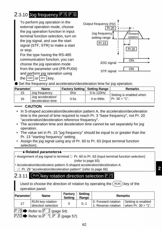
62
2
2.3.10 Jog frequency
To perform jog operation in theexternal operation mode, choosethe jog operation function in inputterminal function selection, turn onthe jog signal, and use the startsignal (STF, STR) to make a startor stop.For the type having the RS-485communication function, you canchoose the jog operation modefrom the parameter unit (FR-PU04)and perform jog operation usingthe FWD or REV key.
Output frequency (Hz)
ON
Pr.20
Forwardrotation
Pr.16
Jog frequency setting range
Pr.15
JOG signal
STF signalON
Set the frequency and acceleration/deceleration time for jog operation.
Parameter Name Factory Setting Setting Range Remarks15 Jog frequency 5Hz 0 to 120Hz
16Jog acceleration/deceleration time
0.5s 0 to 999sSetting is enabled whenPr. 30 = "1".
CAUTION• In S-shaped acceleration/deceleration pattern A, the acceleration/deceleration
time is the period of time required to reach Pr. 3 "base frequency", not Pr. 20"acceleration/deceleration reference frequency".
• The acceleration time and deceleration time cannot be set separately for jogoperation.
• The value set in Pr. 15 "jog frequency" should be equal to or greater than thePr. 13 "starting frequency" setting.
• Assign the jog signal using any of Pr. 60 to Pr. 63 (input terminal functionselection).
♦♦♦♦ Related parameters♦♦♦♦ Assignment of jog signal to terminal ⇒ Pr. 60 to Pr. 63 (input terminal function selection)
(refer to page 83) Acceleration/deceleration pattern S-shaped acceleration/deceleration A⇒ Pr. 29 "acceleration/deceleration pattern" (refer to page 66)
2.3.11 RUN key rotation direction selection
Used to choose the direction of rotation by operating the RUN key of theoperation panel.
Parameter NameFactorySetting
SettingRange
Remarks
17RUN key rotationdirection selection
0 0, 10: Forward rotation1: Reverse rotation
Setting is enabledwhen Pr. 30 = "1".
Refer to (page 54)
Refer to , (page 57)
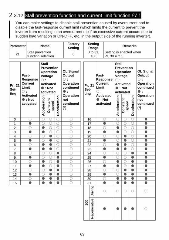
63
2.3.12 Stall prevention function and current limit function You can make settings to disable stall prevention caused by overcurrent and todisable the fast-response current limit (which limits the current to prevent theinverter from resulting in an overcurrent trip if an excessive current occurs due tosudden load variation or ON-OFF, etc. in the output side of the running inverter).
Parameter NameFactorySetting
SettingRange
Remarks
21Stall preventionfunction selection
00 to 31,
100Setting is enabled whenPr. 30 = "1".
StallPreventionOperationVoltage
:Activated
: Notactivated
StallPreventionOperationVoltage
:Activated
: Notactivated
Pr. 21Set-ting
Fast-ResponseCurrentLimit
:Activated
: Notactivated
Ac
cele
rati
on
Co
nst
ant
s pee
d
Dec
eler
atio
n
OL SignalOutput
:Operationcontinued
:Operationnotcontinued(*)
Pr. 21Set-ting
Fast-ResponseCurrentLimit
:Activated
: Notactivated
Ac
cele
rati
on
Co
nst
ant
spee
d
Dec
eler
atio
n
OL SignalOutput
:Operationcontinued
:Operationnotcontinued(*)
0 161 172 183 194 205 216 227 238 249 2510 2611 2712 2813 2914 3015 31
Dri
ving
100
Reg
ene
rativ
e
64
2
CAUTION
•* When "Operation not continued for OL signal output" is selected, the "OLT" alarmcode (stopped by stall prevention) is displayed and operation stopped.(Alarm stop display " ")
• If the load is heavy, the lift is predetermined, or the acceleration/deceleration timeis short, the stall prevention may be activated and the motor not stopped in thepreset acceleration/deceleration time. Therefore, set optimum values to the Pr. 21and stall prevention operation level.
• When the fast-response current limit has been set in Pr. 21 (factory setting),torque will not be provided at the Pr. 22 setting of 170% or higher. At this time,make setting so that the fast-response current limit is not activated.
CAUTION Always perform test operation.Stall prevention operation performed during acceleration may increase theacceleration time.Stall prevention operation performed during constant speed may cause suddenspeed changes.Stall prevention operation performed during deceleration may increase thedeceleration time, increasing the deceleration distance.
2.3.13 Stall prevention Set the output current level at which the output frequency will be adjusted toprevent the inverter from stopping due to overcurrent etc.
During high-speed operation above the rated motor frequency, accelerationmay not be made because the motor current does not increase. To improvethe operating characteristics of the motor in this case, the stall prevention levelcan be reduced in the high frequency region. This function is effective forperforming operation up to the high speed range on a centrifugal separatoretc. Normally, set 60Hz <50Hz> in Pr. 28 "stall prevention operation reductionstarting frequency" and 100% in Pr. 23.
Parameter NameFactorySetting
<EC version>
SettingRange
Remarks
22 Stall prevention operationlevel 150% 0 to 200%
23Stall prevention operationlevel compensation factorat double speed
- - - 0 to200%, - - -
- - -: Pr. 22equally
28 Stall prevention operationreduction starting frequency
60Hz<50Hz>
0 to120Hz
Setting isenabledwhenPr. 30 = "1".
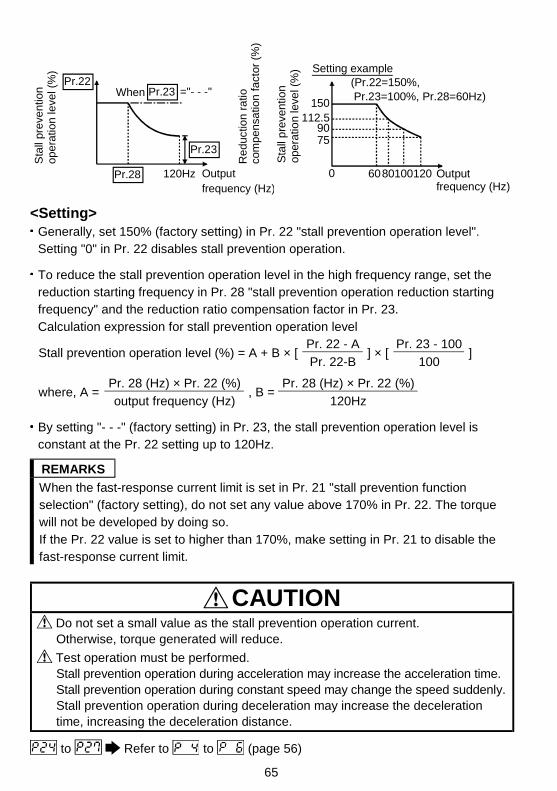
65
120Hz
Pr.22
Pr.28
Pr.23
Sta
ll pr
eve
ntio
n
op
era
tion
leve
l (%
)
Output frequency (Hz)
Re
du
ctio
n r
atio
co
mp
en
satio
n f
act
or (
%)
="- - -"Pr.23When
Setting example(Pr.22=150%, Pr.23=100%, Pr.28=60Hz)
150
9075
0 6080100120
112.5
Sta
ll p
reve
ntio
n op
erat
ion
leve
l (%
)
Output frequency (Hz)
<Setting>Generally, set 150% (factory setting) in Pr. 22 "stall prevention operation level".Setting "0" in Pr. 22 disables stall prevention operation.
To reduce the stall prevention operation level in the high frequency range, set thereduction starting frequency in Pr. 28 "stall prevention operation reduction startingfrequency" and the reduction ratio compensation factor in Pr. 23.Calculation expression for stall prevention operation level
Pr. 22 - A Pr. 23 - 100Stall prevention operation level (%) = A + B × [
Pr. 22-B ] × [
100 ]
Pr. 28 (Hz) × Pr. 22 (%) Pr. 28 (Hz) × Pr. 22 (%)where, A =
output frequency (Hz) , B =
120Hz
By setting "- - -" (factory setting) in Pr. 23, the stall prevention operation level isconstant at the Pr. 22 setting up to 120Hz.
REMARKS
When the fast-response current limit is set in Pr. 21 "stall prevention functionselection" (factory setting), do not set any value above 170% in Pr. 22. The torquewill not be developed by doing so.If the Pr. 22 value is set to higher than 170%, make setting in Pr. 21 to disable thefast-response current limit.
CAUTION Do not set a small value as the stall prevention operation current.Otherwise, torque generated will reduce.
Test operation must be performed.Stall prevention operation during acceleration may increase the acceleration time.Stall prevention operation during constant speed may change the speed suddenly.Stall prevention operation during deceleration may increase the decelerationtime, increasing the deceleration distance.
to Refer to to (page 56)
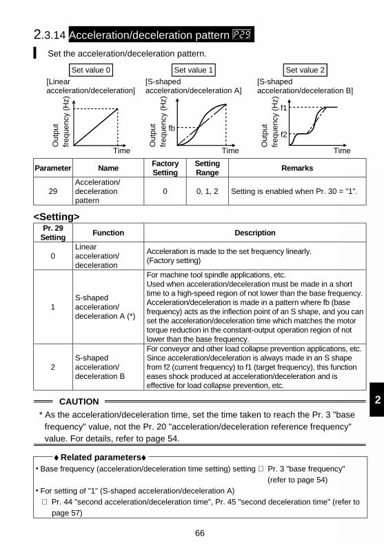
66
2
2.3.14 Acceleration/deceleration pattern
Set the acceleration/deceleration pattern.
Out
put
freq
uenc
y (H
z)
fb
Time
[S-shaped acceleration/deceleration A]
Set value 1
f1
f2
Out
put
freq
uenc
y (H
z)
[S-shaped acceleration/deceleration B]
Set value 2
Time
Set value 0
Time
Out
put
freq
uenc
y (H
z)
[Linearacceleration/deceleration]
Parameter NameFactorySetting
SettingRange
Remarks
29Acceleration/decelerationpattern
0 0, 1, 2 Setting is enabled when Pr. 30 = "1".
<Setting>Pr. 29
SettingFunction Description
0Linearacceleration/deceleration
Acceleration is made to the set frequency linearly.(Factory setting)
1S-shapedacceleration/deceleration A (*)
For machine tool spindle applications, etc.Used when acceleration/deceleration must be made in a shorttime to a high-speed region of not lower than the base frequency.Acceleration/deceleration is made in a pattern where fb (basefrequency) acts as the inflection point of an S shape, and you canset the acceleration/deceleration time which matches the motortorque reduction in the constant-output operation region of notlower than the base frequency.
2S-shapedacceleration/deceleration B
For conveyor and other load collapse prevention applications, etc.Since acceleration/deceleration is always made in an S shapefrom f2 (current frequency) to f1 (target frequency), this functioneases shock produced at acceleration/deceleration and iseffective for load collapse prevention, etc.
CAUTION
* As the acceleration/deceleration time, set the time taken to reach the Pr. 3 "basefrequency" value, not the Pr. 20 "acceleration/deceleration reference frequency"value. For details, refer to page 54.
♦♦♦♦ Related parameters♦♦♦♦ Base frequency (acceleration/deceleration time setting) setting ⇒ Pr. 3 "base frequency"
(refer to page 54)
For setting of "1" (S-shaped acceleration/deceleration A)
⇒ Pr. 44 "second acceleration/deceleration time", Pr. 45 "second deceleration time" (refer to
page 57)
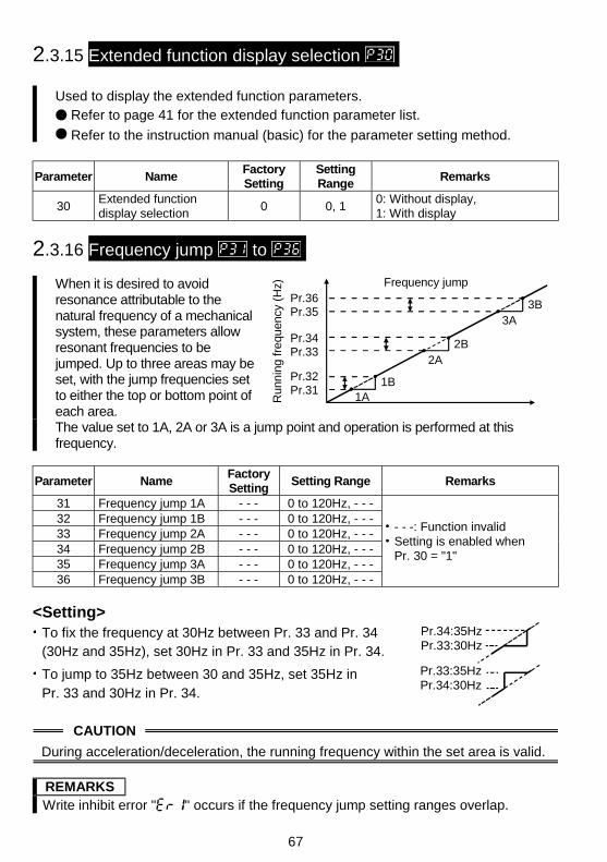
67
2.3.15 Extended function display selection
Used to display the extended function parameters.
Refer to page 41 for the extended function parameter list.
Refer to the instruction manual (basic) for the parameter setting method.
Parameter NameFactorySetting
SettingRange
Remarks
30Extended functiondisplay selection
0 0, 10: Without display,1: With display
2.3.16 Frequency jump to
When it is desired to avoidresonance attributable to thenatural frequency of a mechanicalsystem, these parameters allowresonant frequencies to bejumped. Up to three areas may beset, with the jump frequencies setto either the top or bottom point ofeach area.
Pr.33Pr.34 2B
2A
Pr.36Pr.35
Pr.32Pr.31
Frequency jump
3B3A
1B1AR
unn
ing
fre
quen
cy (
Hz)
The value set to 1A, 2A or 3A is a jump point and operation is performed at thisfrequency.
Parameter NameFactorySetting
Setting Range Remarks
31 Frequency jump 1A - - - 0 to 120Hz, - - -32 Frequency jump 1B - - - 0 to 120Hz, - - -33 Frequency jump 2A - - - 0 to 120Hz, - - -34 Frequency jump 2B - - - 0 to 120Hz, - - -35 Frequency jump 3A - - - 0 to 120Hz, - - -36 Frequency jump 3B - - - 0 to 120Hz, - - -
- - -: Function invalidSetting is enabled whenPr. 30 = "1"
<Setting>To fix the frequency at 30Hz between Pr. 33 and Pr. 34(30Hz and 35Hz), set 30Hz in Pr. 33 and 35Hz in Pr. 34.
Pr.34:35HzPr.33:30Hz
To jump to 35Hz between 30 and 35Hz, set 35Hz inPr. 33 and 30Hz in Pr. 34.
Pr.33:35HzPr.34:30Hz
CAUTION
During acceleration/deceleration, the running frequency within the set area is valid.
REMARKSWrite inhibit error " " occurs if the frequency jump setting ranges overlap.
68
2
2.3.17 Speed display
You can change the output frequency indication of the operation panel andparameter unit (FR-PU04) to the motor speed or machine speed.
Parameter NameFactorySetting
SettingRange
Remarks
37 Speed display 0 0, 0.1 to 9990: Output
frequencySetting is enabledwhen Pr. 30 = "1".
<Setting>To display the machine speed, set in Pr. 37 the machine speed for 60Hz operation.
CAUTION
• The motor speed is converted from the output frequency and does not match theactual speed.
• When you want to change the monitor (PU main display) of the operation panel,refer to Pr. 52 "operation panel display data selection" and communicationparameter n16 "PU main display screen data selection".
• Since the operation panel indication is 3 digits, make a setting so that the monitorvalue does not exceed "999". If the Pr. 1 value is higher than 60Hz andPr. 1 value × Pr. 37 value > 60Hz × 999
(write error) occurs when Pr. 1 or Pr. 37 is written.
REMARKSWhen you set the speed in Pr. 37, the speed is monitored in the monitor frequencysetting mode.At this time, setting can be made in the minimum setting increments of 0.01r/min.Due to the restrictions on the resolution of the set frequency, the indication in thesecond decimal place may differ from the setting.
CAUTION Make sure that the running speed setting is correct.Otherwise, the motor might run at extremely high speed, damaging the machine.
♦♦♦♦ Related parameters♦♦♦♦ To choose running speed monitor display ⇒ Pr. 52 "operation panel display data selection"
(refer to page 77) FR-PU04 display switching ⇒ Communication parameter n16 "PU main display screen data
selection" (refer to page 128)
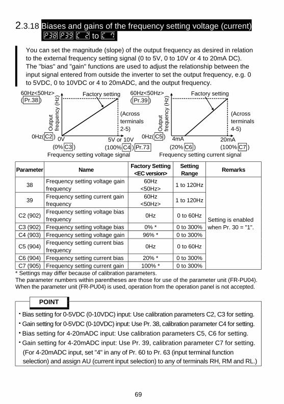
69
2.3.18 Biases and gains of the frequency setting voltage (current) to
You can set the magnitude (slope) of the output frequency as desired in relationto the external frequency setting signal (0 to 5V, 0 to 10V or 4 to 20mA DC).The "bias" and "gain" functions are used to adjust the relationship between theinput signal entered from outside the inverter to set the output frequency, e.g. 0to 5VDC, 0 to 10VDC or 4 to 20mADC, and the output frequency.
Frequency setting voltage signal
Factory setting
0Hz( )C2 5V or 10V (100% C4 )
0V
Pr.73
Out
put
fre
quen
cy (
Hz)( Pr.38 )
60Hz<50Hz>
Frequency setting current signal
20mA4mA
Factory setting( Pr.39 )60Hz<50Hz>
Out
put
fre
quen
cy (
Hz)
0Hz( )C5
(0% C3 )
(Across terminals 2-5)
(20% C6 ) (100% C7 )
(Across terminals 4-5)
Parameter NameFactory Setting
<EC version>SettingRange
Remarks
38Frequency setting voltage gainfrequency
60Hz<50Hz>
1 to 120Hz
39Frequency setting current gainfrequency
60Hz<50Hz>
1 to 120Hz
C2 (902)Frequency setting voltage biasfrequency
0Hz 0 to 60Hz
C3 (902) Frequency setting voltage bias 0% * 0 to 300%C4 (903) Frequency setting voltage gain 96% * 0 to 300%
C5 (904)Frequency setting current biasfrequency
0Hz 0 to 60Hz
C6 (904) Frequency setting current bias 20% * 0 to 300%C7 (905) Frequency setting current gain 100% * 0 to 300%
Setting is enabledwhen Pr. 30 = "1".
* Settings may differ because of calibration parameters.The parameter numbers within parentheses are those for use of the parameter unit (FR-PU04).When the parameter unit (FR-PU04) is used, operation from the operation panel is not accepted.
POINT
Bias setting for 0-5VDC (0-10VDC) input: Use calibration parameters C2, C3 for setting.
Gain setting for 0-5VDC (0-10VDC) input: Use Pr. 38, calibration parameter C4 for setting.
Bias setting for 4-20mADC input: Use calibration parameters C5, C6 for setting.
Gain setting for 4-20mADC input: Use Pr. 39, calibration parameter C7 for setting.
(For 4-20mADC input, set "4" in any of Pr. 60 to Pr. 63 (input terminal functionselection) and assign AU (current input selection) to any of terminals RH, RM and RL.)
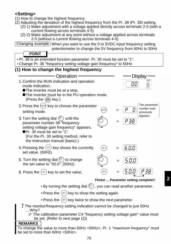
70
2
<Setting>(1) How to change the highest frequency(2) Adjusting the deviation of the highest frequency from the Pr. 38 (Pr. 39) setting.
(2)-1) Make adjustment with a voltage applied directly across terminals 2-5 (with acurrent flowing across terminals 4-5)
(2)-2) Make adjustment at any point without a voltage applied across terminals2-5 (without a current flowing across terminals 4-5)
Changing example When you want to use the 0 to 5VDC input frequency settingpotentiometer to change the 5V frequency from 60Hz to 50Hz
POINT
Pr. 38 is an extended function parameter. Pr. 30 must be set to "1". Change Pr. 38 "frequency setting voltage gain frequency" to 50Hz.
(1) How to change the highest frequency
Confirm the RUN indication and operation mode indication. The inverter must be at a stop. The inverter must be in the PU operation mode. (Press the key.)
2.MODE
1.
MODE
RUN
PU
EXT
PUEXT
Press the key to choose the parameter
setting mode.
The parameternumber readpreviouslyappears.
DisplayOperation
4. SETPressing the key shows the currently set value. (60Hz)
SET
3.Turn the setting dial until the parameter number 38 "frequency setting voltage gain frequency" appears. Pr. 30 must be set to "1". (For the Pr. 30 setting method, refer to the instruction manual (basic).)
5. Turn the setting dial to change the set value to "50.0". (50Hz)
6. Press the key to set the value.SET
Flicker ... Parameter setting complete!!
SET
SET
SET
By turning the setting dial , you can read another parameter.
Press the key to show the setting again.
Press the key twice to show the next parameter.
The monitor/frequency setting indication cannot be changed to just 50Hz... Why?
The calibration parameter C4 "frequency setting voltage gain" value mustbe set. (Refer to next page (2))
REMARKSTo change the value to more than 60Hz <50Hz>, Pr. 1 "maximum frequency" mustbe set to more than 60Hz <50Hz>.
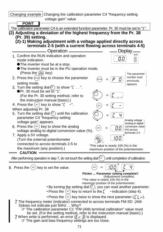
71
Changing example Changing the calibration parameter C4 "frequency settingvoltage gain" value
POINTThe calibration parameter C4 is an extended function parameter. Pr. 30 must be set to "1".
(2) Adjusting a deviation of the highest frequency from the Pr. 38(Pr. 39) setting.(2)-1) Making adjustment with a voltage applied directly across
terminals 2-5 (with a current flowing across terminals 4-5)
Confirm the RUN indication and operation mode indication. The inverter must be at a stop. The inverter must be in the PU operation mode. (Press the key)
1.
4.
5.
SET
2. MODEMODE
The parameternumber readpreviouslyappears.
6. Press the key to show the analog voltage analog-to-digital conversion value (%).
SETSET
7. Apply a 5V voltage.(Turn the external potentiometer connected to across terminals 2-5 to the maximum (any position).)
123
4 5 67
8
9
10
Analog voltage analog-to-digital conversion value (%) across terminals 2-5
*
Press the key to choose the parameter
setting mode.
RUN
PU
EXT
*The value is nearly 100 (%) in the maximum position of the potentiometer.
3. Turn the setting dial to show " ". Pr. 30 must be set to "1". (For the Pr. 30 setting method, refer to the instruction manual (basic).)
PUEXT
Turn the setting dial until the calibration parameter C4 "frequency setting voltage gain" appears.
SETPress the key to show " ".
DisplayOperation
When adjusting Pr. 38
CAUTION
After performing operation in step 7, do not touch the setting dial until completion of calibration.
Flicker ... Parameter setting complete!!
*The value is nearly 100 (%) in the maximum position of the potentiometer.
8. SET
(Adjustment complete)
*SETPress the key to set the value.
By turning the setting dial , you can read another parameter.SET Press the key to return to the indication (step 4).SET Press the key twice to show the next parameter ( ).
The frequency meter (indicator) connected to across terminals FM-SD (AM-5)does not indicate just 50Hz ... Why?
The calibration parameter C1 "FM (AM) terminal calibration" value mustbe set. (For the setting method, refer to the instruction manual (basic).)
When write is performed, an error ( ) is displayed. The gain and bias frequency settings are too close.
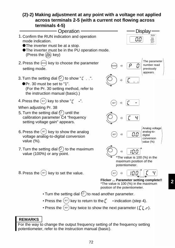
72
2
(2)-2) Making adjustment at any point with a voltage not appliedacross terminals 2-5 (with a current not flowing acrossterminals 4-5)
Confirm the RUN indication and operation mode indication. The inverter must be at a stop. The inverter must be in the PU operation mode. (Press the key)
SET
SET
MODE
Analog voltage analog-to-digital conversion value (%)
Flicker ... Parameter setting complete!!
SET
*The value is 100 (%) in the maximum position of the potentiometer.
*
3.
4.
5.
6.
2.
1.
8.
7. *
Turn the setting dial to show " ".
Pr. 30 must be set to "1". (For the Pr. 30 setting method, refer to the instruction manual (basic).)
Press the key to show " ".SET
Turn the setting dial until the calibration parameter C4 "frequency setting voltage gain" appears.
Press the key to show the analog voltage analog-to-digital conversion value (%).
SET
Turn the setting dial to the maximum value (100%) or any point.
SETPress the key to set the value.
MODEPress the key to choose the parameter
setting mode.
The parameternumber readpreviouslyappears.
RUN
PU
EXT
*The value is 100 (%) in the maximum position of the potentiometer.
PUEXT
DisplayOperation
When adjusting Pr. 38
Turn the setting dial to read another parameter.
SET Press the key to return to the indication (step 4).
SET Press the key twice to show the next parameter ( ).
REMARKSFor the way to change the output frequency setting of the frequency settingpotentiometer, refer to the instruction manual (basic).
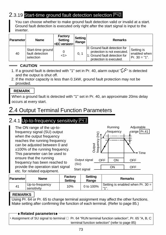
73
2.3.19 Start-time ground fault detection selection You can choose whether to make ground fault detection valid or invalid at a start.Ground fault detection is executed only right after the start signal is input to theinverter.
Parameter NameFactorySetting
<EC version>
SettingRange
Remarks
40Start-time groundfault detectionselection
0<1> 0, 1
0: Ground fault detection forprotection is not executed.
1: Ground fault detection forprotection is executed.
Setting isenabled whenPr. 30 = "1".
CAUTION1. If a ground fault is detected with "1" set in Pr. 40, alarm output " " is detected
and the output is shut off.2. If the motor capacity is less than 0.1kW, ground fault protection may not be
provided.
REMARK
When a ground fault is detected with "1" set in Pr. 40, an approximate 20ms delayoccurs at every start.
2.4 Output Terminal Function Parameters
2.4.1 Up-to-frequency sensitivity The ON range of the up-to-frequency signal (SU) outputwhen the output frequencyreaches the running frequencycan be adjusted between 0 and±100% of the running frequency.This parameter can be used toensure that the runningfrequency has been reached toprovide the operation start signaletc. for related equipment.
Running frequency
Adjustable range
Output signal (SU)
Time
Start signal
Ou
tput
fr
eque
ncy
(Hz) Pr.41
OFF ON OFF
ON OFF
Parameter NameFactorySetting
SettingRange
Remarks
41Up-to-frequencysensitivity
10% 0 to 100%Setting is enabled when Pr. 30 ="1".
REMARKSUsing Pr. 64 or Pr. 65 to change terminal assignment may affect the other functions.Make setting after confirming the function of each terminal. (Refer to page 85.)
♦♦♦♦ Related parameters♦♦♦♦ Assignment of SU signal to terminal ⇒ Pr. 64 "RUN terminal function selection", Pr. 65 "A, B, C
terminal function selection" (refer to page 85)
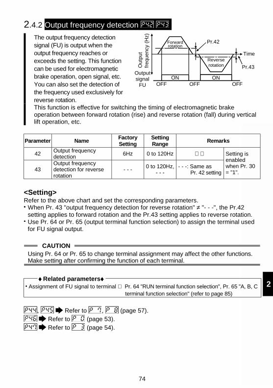
74
2
2.4.2 Output frequency detection
The output frequency detectionsignal (FU) is output when theoutput frequency reaches orexceeds the setting. This functioncan be used for electromagneticbrake operation, open signal, etc.You can also set the detection ofthe frequency used exclusively forreverse rotation.
Forwardrotation
Reverserotation
Time
Output signal
FU
Outp
ut
freq
uen
cy (
Hz)
Pr.42
Pr.43
ON ONOFF OFF OFF
This function is effective for switching the timing of electromagnetic brakeoperation between forward rotation (rise) and reverse rotation (fall) during verticallift operation, etc.
Parameter NameFactorySetting
SettingRange
Remarks
42Output frequencydetection 6Hz 0 to 120Hz
43Output frequencydetection for reverserotation
- - - 0 to 120Hz,- - -
- - -: Same asPr. 42 setting
Setting isenabledwhen Pr. 30= "1".
<Setting>Refer to the above chart and set the corresponding parameters.
When Pr. 43 "output frequency detection for reverse rotation" ≠ "- - -", the Pr.42setting applies to forward rotation and the Pr.43 setting applies to reverse rotation.Use Pr. 64 or Pr. 65 (output terminal function selection) to assign the terminal usedfor FU signal output.
CAUTIONUsing Pr. 64 or Pr. 65 to change terminal assignment may affect the other functions.Make setting after confirming the function of each terminal.
♦♦♦♦ Related parameters♦♦♦♦ Assignment of FU signal to terminal ⇒ Pr. 64 "RUN terminal function selection", Pr. 65 "A, B, C
terminal function selection" (refer to page 85)
, Refer to , (page 57). Refer to (page 53). Refer to (page 54).
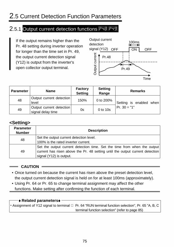
75
2.5 Current Detection Function Parameters
2.5.1 Output current detection functions
If the output remains higher than thePr. 48 setting during inverter operationfor longer than the time set in Pr. 49,the output current detection signal(Y12) is output from the inverter'sopen collector output terminal.
Out
put c
urre
nt
Time
Output current detection signal (Y12)
100ms
Pr.48
Pr.49
OFF OFFON
Parameter NameFactorySetting
SettingRange
Remarks
48Output current detectionlevel
150% 0 to 200%
49Output current detectionsignal delay time
0s 0 to 10s
Setting is enabled whenPr. 30 = "1"
<Setting>Parameter
NumberDescription
48Set the output current detection level.100% is the rated inverter current.
49Set the output current detection time. Set the time from when the outputcurrent has risen above the Pr. 48 setting until the output current detectionsignal (Y12) is output.
CAUTION
• Once turned on because the current has risen above the preset detection level,the output current detection signal is held on for at least 100ms (approximately).
• Using Pr. 64 or Pr. 65 to change terminal assignment may affect the otherfunctions. Make setting after confirming the function of each terminal.
♦♦♦♦ Related parameters♦♦♦♦ Assignment of Y12 signal to terminal ⇒ Pr. 64 "RUN terminal function selection", Pr. 65 "A, B, C
terminal function selection" (refer to page 85)

76
2
2.5.2 Zero current detection
When the inverter'soutput current falls to"0", torque will not begenerated. This maycause a gravity dropwhen the inverter isused in vertical liftapplication.
ONStart signal
OFF
Pr.50
Pr.51 detection time
OFF OFF100ms
ON ON
Pr.51 detection time
Pr.50 "zero current detectionlevel"
Output current 0 [A]Zero current detection signal output (Y13)
To prevent this, the output current "zero" signal can be output from the inverter toclose the mechanical brake when the output current has fallen to "zero".
Parameter NameFactorySetting
SettingRange
Remarks
50Zero current detectionlevel
5% 0 to 200%
51Zero current detectiontime
0.5s 0.05 to 1s
Setting is enabled when Pr. 30= "1"
POINT
If the output is lower than the Pr.50 setting for longer than the time set in Pr. 51during inverter operation, the zero current detection (Y13) signal is output from theinverter's open collector output terminal.
<Setting>Parameter Description
50Set the zero current detection level.Set the level of zero current detection in terms of the percentage of the ratedinverter current from the output current value of 0 [A].
51Set the zero current detection time.Set a period of time from when the output current falls to or below the Pr. 50setting to when the zero current detection signal (Y13) is output.
CAUTION• If the current falls below the preset detection level but the timing condition is not
satisfied, the zero current detection signal is held on for about 100ms.• When the terminal functions are changed using Pr. 64, Pr. 65, the other functions
may be affected. Confirm the functions of the corresponding terminals beforemaking settings.
• When one inverter is used to run (connect) multiple motors sequentially, the zerocurrent detection signal (Y13) may be output. Set 13% or more for the 0.1K, and8% or more for the 0.2K. (If the sum of motor capacities is less than the zerocurrent detection level current or if the motor capacity per motor is less than thezero current detection level current)
♦♦♦♦ Related parameters♦♦♦♦ Assignment of Y13 signal to terminal ⇒ Pr. 64 "RUN terminal function selection", Pr. 65 "A, B, C
terminal function selection" (refer to page85)
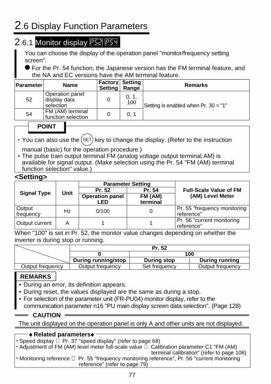
77
2.6 Display Function Parameters
2.6.1 Monitor display You can choose the display of the operation panel "monitor/frequency settingscreen".
For the Pr. 54 function, the Japanese version has the FM terminal feature, andthe NA and EC versions have the AM terminal feature.
Parameter Name FactorySetting
SettingRange Remarks
52Operation paneldisplay dataselection
0 0, 1,100
54 FM (AM) terminalfunction selection 0 0, 1
Setting is enabled when Pr. 30 = "1"
POINT
You can also use the SET key to change the display. (Refer to the instruction
manual (basic) for the operation procedure.)The pulse train output terminal FM (analog voltage output terminal AM) isavailable for signal output. (Make selection using the Pr. 54 "FM (AM) terminalfunction selection" value.)
<Setting>Parameter Setting
Pr. 52 Pr. 54Signal Type UnitOperation panel
LEDFM (AM)terminal
Full-Scale Value of FM(AM) Level Meter
Outputfrequency Hz 0/100 0 Pr. 55 "frequency monitoring
reference"
Output current A 1 1 Pr. 56 "current monitoringreference"
When "100" is set in Pr. 52, the monitor value changes depending on whether theinverter is during stop or running.
Pr. 520 100
During running/stop During stop During runningOutput frequency Output frequency Set frequency Output frequency
REMARKS• During an error, its definition appears.• During reset, the values displayed are the same as during a stop.• For selection of the parameter unit (FR-PU04) monitor display, refer to the
communication parameter n16 "PU main display screen data selection". (Page 128)
CAUTIONThe unit displayed on the operation panel is only A and other units are not displayed.
♦♦♦♦ Related parameters♦♦♦♦ Speed display ⇒ Pr. 37 "speed display" (refer to page 68) Adjustment of FM (AM) level meter full-scale value ⇒ Calibration parameter C1 "FM (AM)
terminal calibration" (refer to page 106) Monitoring reference ⇒ Pr. 55 "frequency monitoring reference", Pr. 56 "current monitoring
reference" (refer to page 79)
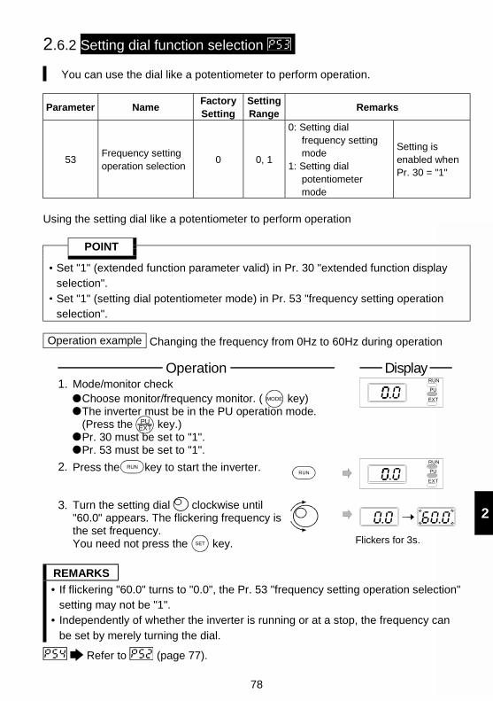
78
2
2.6.2 Setting dial function selection
You can use the dial like a potentiometer to perform operation.
Parameter NameFactorySetting
SettingRange
Remarks
53Frequency settingoperation selection
0 0, 1
0: Setting dialfrequency settingmode
1: Setting dialpotentiometermode
Setting isenabled whenPr. 30 = "1"
Using the setting dial like a potentiometer to perform operation
POINT
Set "1" (extended function parameter valid) in Pr. 30 "extended function displayselection".Set "1" (setting dial potentiometer mode) in Pr. 53 "frequency setting operationselection".
Operation example Changing the frequency from 0Hz to 60Hz during operation
Choose monitor/frequency monitor. ( key) The inverter must be in the PU operation mode. (Press the key.) Pr. 30 must be set to "1". Pr. 53 must be set to "1".
1.
PUEXT
Mode/monitor check RUN
PU
EXTMODE
RUN
PU
EXT
RUN
3. Turn the setting dial clockwise until "60.0" appears. The flickering frequency is the set frequency.You need not press the key.
2. Press the key to start the inverter.RUN
SET Flickers for 3s.
DisplayOperation
REMARKS
• If flickering "60.0" turns to "0.0", the Pr. 53 "frequency setting operation selection"setting may not be "1".
• Independently of whether the inverter is running or at a stop, the frequency canbe set by merely turning the dial.
Refer to (page 77).
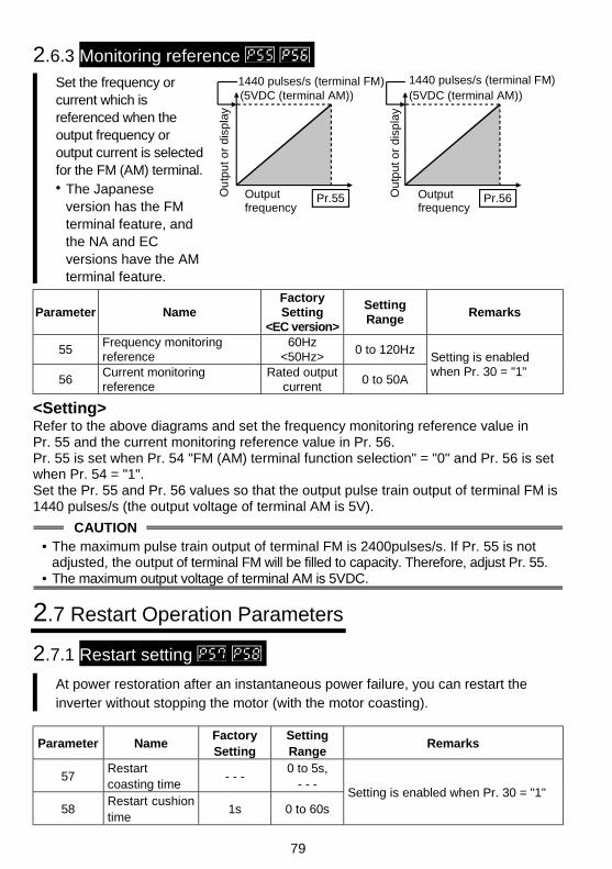
79
2.6.3 Monitoring reference Set the frequency orcurrent which isreferenced when theoutput frequency oroutput current is selectedfor the FM (AM) terminal.• The Japanese
version has the FMterminal feature, andthe NA and ECversions have the AMterminal feature.
1440 pulses/s (terminal FM)
Output frequency
Pr.55
1440 pulses/s (terminal FM)
Output frequency
Pr.56Ou
tput
or
disp
lay
Ou
tput
or
disp
lay
(5VDC (terminal AM)) (5VDC (terminal AM))
Parameter NameFactorySetting
<EC version>
SettingRange
Remarks
55Frequency monitoringreference
60Hz<50Hz>
0 to 120Hz
56Current monitoringreference
Rated outputcurrent
0 to 50A
Setting is enabledwhen Pr. 30 = "1"
<Setting>Refer to the above diagrams and set the frequency monitoring reference value inPr. 55 and the current monitoring reference value in Pr. 56.Pr. 55 is set when Pr. 54 "FM (AM) terminal function selection" = "0" and Pr. 56 is setwhen Pr. 54 = "1".Set the Pr. 55 and Pr. 56 values so that the output pulse train output of terminal FM is1440 pulses/s (the output voltage of terminal AM is 5V).
CAUTION• The maximum pulse train output of terminal FM is 2400pulses/s. If Pr. 55 is not
adjusted, the output of terminal FM will be filled to capacity. Therefore, adjust Pr. 55.• The maximum output voltage of terminal AM is 5VDC.
2.7 Restart Operation Parameters
2.7.1 Restart setting
At power restoration after an instantaneous power failure, you can restart theinverter without stopping the motor (with the motor coasting).
Parameter NameFactorySetting
SettingRange
Remarks
57Restartcoasting time
- - -0 to 5s,
- - -
58Restart cushiontime
1s 0 to 60sSetting is enabled when Pr. 30 = "1"
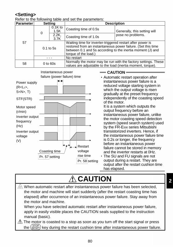
80
2
<Setting>Refer to the following table and set the parameters:Parameter Setting Description
0.1K to1.5K Coasting time of 0.5s
02.2K,3.7K Coasting time of 1.0s
Generally, this setting willpose no problems.
0.1 to 5s
Waiting time for inverter-triggered restart after power isrestored from an instantaneous power failure. (Set this timebetween 0.1 and 5s according to the inertia moment (J) andtorque of the load.)
57
- - - No restart
58 0 to 60s Normally the motor may be run with the factory settings. Thesevalues are adjustable to the load (inertia moment, torque).
CAUTIONInstantaneous power failure (power failure) time
Power supply (R<L1>, S<N>, T)
STF(STR)
Motor speed(r/min)
Inverter output frequency(Hz)
Inverter output voltage(V)
Coasting time
Pr. 57 setting
Restart voltage rise time
Pr. 58 setting
Automatic restart operation afterinstantaneous power failure is areduced voltage starting system inwhich the output voltage is risengradually at the preset frequencyindependently of the coasting speedof the motor.It is a system which outputs theoutput frequency before aninstantaneous power failure, unlikethe motor coasting speed detectionsystem (speed search system) usedby the FR-E500 series Mitsubishitransistorized inverters. Hence, ifthe instantaneous power failure timeis 0.2s or longer, the frequencybefore an instantaneous powerfailure cannot be stored in memoryand the inverter restarts at 0Hz.The SU and FU signals are notoutput during a restart. They areoutput after the restart cushion timehas elapsed.
CAUTION When automatic restart after instantaneous power failure has been selected,the motor and machine will start suddenly (after the restart coasting time haselapsed) after occurrence of an instantaneous power failure. Stay away fromthe motor and machine.When you have selected automatic restart after instantaneous power failure,apply in easily visible places the CAUTION seals supplied to the instructionmanual (basic).
The motor is coasted to a stop as soon as you turn off the start signal or press
the STOP
RESET key during the restart cushion time after instantaneous power failure.
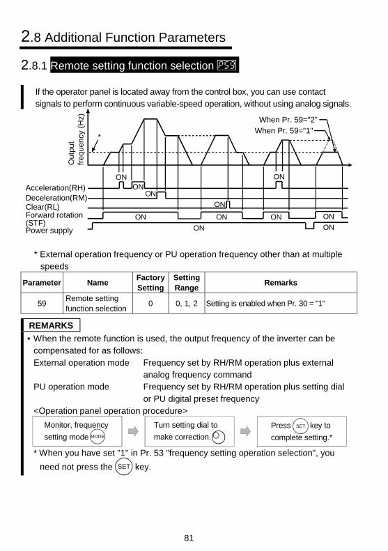
81
2.8 Additional Function Parameters
2.8.1 Remote setting function selection
If the operator panel is located away from the control box, you can use contactsignals to perform continuous variable-speed operation, without using analog signals.
Deceleration(RM)Clear(RL)
Acceleration(RH)
Forward rotation(STF)
Out
put
freq
uen
cy (
Hz)
ON ON
Power supply ON
*
ON
ON
ONON
ON
When Pr. 59="2"
When Pr. 59="1"
ON ON
ON
* External operation frequency or PU operation frequency other than at multiplespeeds
Parameter NameFactorySetting
SettingRange
Remarks
59Remote settingfunction selection
0 0, 1, 2 Setting is enabled when Pr. 30 = "1"
REMARKS
• When the remote function is used, the output frequency of the inverter can becompensated for as follows:External operation mode Frequency set by RH/RM operation plus external
analog frequency commandPU operation mode Frequency set by RH/RM operation plus setting dial
or PU digital preset frequency<Operation panel operation procedure>
Monitor, frequency
setting mode MODE
Press key to
complete setting.*
SETTurn setting dial to
make correction.
* When you have set "1" in Pr. 53 "frequency setting operation selection", you
need not press the SET key.
82
2
<Setting>Operation
Pr. 59 SettingRemote setting function
Frequency setting storagefunction (E2PROM)
0 No ——1 Yes Yes2 Yes No
Use Pr. 59 to select whether the remote setting function is used or not and whetherthe frequency setting storage function* in the remote setting mode is used or not.When "remote setting function - yes" is selected, the functions of terminals RH, RMand RL are changed to acceleration (RH), deceleration (RM) and clear (RL).Use Pr. 60 to Pr. 62 (input terminal function selection) to set the signals RH, RM, RL.
* Frequency setting storage functionThe remote setting frequency (frequency set by RH/RM operation) is stored inmemory.When power is switched off once and then on again, the inverter resumesrunning at this setting of output frequency. (Pr. 59="1")
<Frequency setting storage conditions>Frequency as soon as the start signal (STF or STR) turns off.Frequency when the RH (acceleration) or RM (deceleration) signal has remained offfor longer than 1 minute.
CAUTION
• The frequency can be varied by RH (acceleration) and RM (deceleration)between 0 and the maximum frequency (Pr. 1 setting).
• When the acceleration or deceleration signal switches on, the set frequencyvaries according to the slope set in Pr. 44 "second acceleration/deceleration time"or Pr. 45 "second deceleration time". The output frequency acceleration anddeceleration times are as set in Pr. 7 "acceleration time" and Pr. 8 "decelerationtime", respectively. Therefore, the longer preset times are used to vary the actualoutput frequency.
• If the start signal (STF or STR) is off, turning on the acceleration (RH) ordeceleration (RM) signal varies the preset frequency.
83
CAUTION When selecting this function, re-set the maximum frequency according to themachine.
♦♦♦♦ Related parameters♦♦♦♦ Maximum frequency setting ⇒ Pr. 1 "maximum frequency" (refer to page 54) Output frequency acceleration/deceleration time ⇒ Pr. 7 "acceleration time",
Pr. 8 "deceleration time" (refer to page 57) Time setting for acceleration/deceleration ⇒ Pr. 44 "second acceleration/deceleration time",
Pr. 45 "second deceleration time"(refer to page 57)
2.9 Terminal Function Selection Parameters
2.9.1 Input terminal function selection
Use these parameters to select/change the input terminal functions.
Parameter NameFactorySetting
SettingRange
Remarks
60RL terminalfunctionselection
0
61RM terminalfunctionselection
1
62RH terminalfunctionselection
2
0 to 10,14, 16
63STR terminalfunctionselection
- - -0 to 10,14, 16,
- - -
Setting is enabled when Pr. 30 = "1"
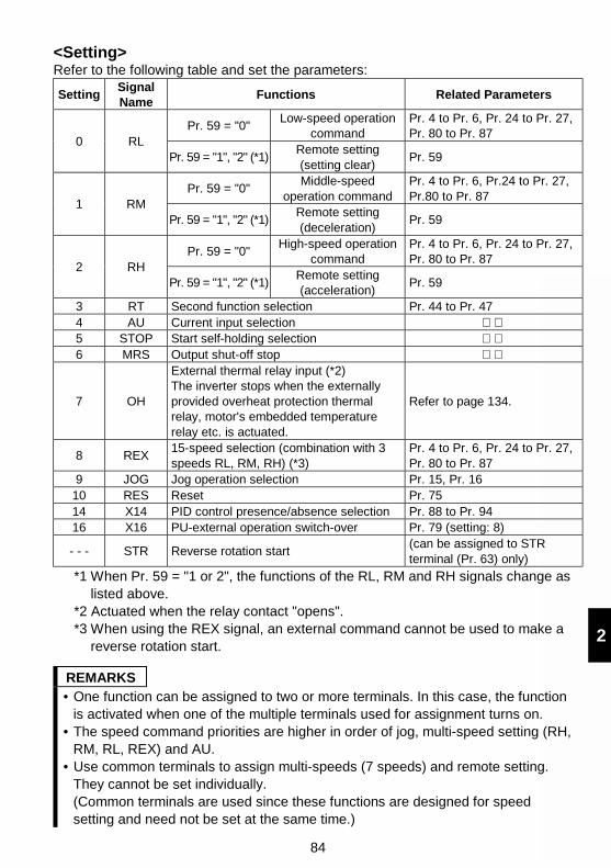
84
2
<Setting>Refer to the following table and set the parameters:
SettingSignalName
Functions Related Parameters
Pr. 59 = "0"Low-speed operation
commandPr. 4 to Pr. 6, Pr. 24 to Pr. 27,Pr. 80 to Pr. 87
0 RLPr. 59 = "1", "2" (*1)
Remote setting(setting clear)
Pr. 59
Pr. 59 = "0"Middle-speed
operation commandPr. 4 to Pr. 6, Pr.24 to Pr. 27,Pr.80 to Pr. 87
1 RMPr. 59 = "1", "2" (*1)
Remote setting(deceleration)
Pr. 59
Pr. 59 = "0"High-speed operation
commandPr. 4 to Pr. 6, Pr. 24 to Pr. 27,Pr. 80 to Pr. 87
2 RHPr. 59 = "1", "2" (*1)
Remote setting(acceleration)
Pr. 59
3 RT Second function selection Pr. 44 to Pr. 474 AU Current input selection 5 STOP Start self-holding selection 6 MRS Output shut-off stop
7 OH
External thermal relay input (*2)The inverter stops when the externallyprovided overheat protection thermalrelay, motor's embedded temperaturerelay etc. is actuated.
Refer to page 134.
8 REX15-speed selection (combination with 3speeds RL, RM, RH) (*3)
Pr. 4 to Pr. 6, Pr. 24 to Pr. 27,Pr. 80 to Pr. 87
9 JOG Jog operation selection Pr. 15, Pr. 1610 RES Reset Pr. 7514 X14 PID control presence/absence selection Pr. 88 to Pr. 9416 X16 PU-external operation switch-over Pr. 79 (setting: 8)
- - - STR Reverse rotation start(can be assigned to STRterminal (Pr. 63) only)
*1 When Pr. 59 = "1 or 2", the functions of the RL, RM and RH signals change aslisted above.
*2 Actuated when the relay contact "opens".*3 When using the REX signal, an external command cannot be used to make a
reverse rotation start.
REMARKS• One function can be assigned to two or more terminals. In this case, the function
is activated when one of the multiple terminals used for assignment turns on.• The speed command priorities are higher in order of jog, multi-speed setting (RH,
RM, RL, REX) and AU.• Use common terminals to assign multi-speeds (7 speeds) and remote setting.
They cannot be set individually.(Common terminals are used since these functions are designed for speedsetting and need not be set at the same time.)
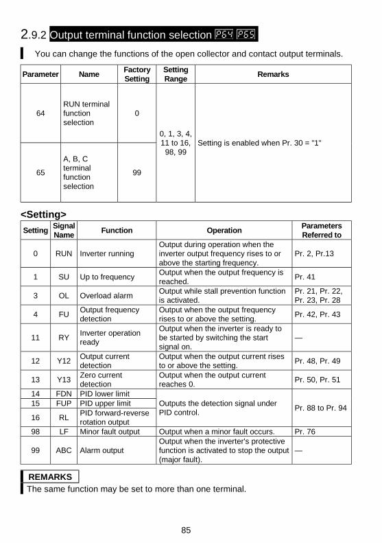
85
2.9.2 Output terminal function selection
You can change the functions of the open collector and contact output terminals.
Parameter NameFactorySetting
SettingRange
Remarks
64RUN terminalfunctionselection
0
65
A, B, Cterminalfunctionselection
99
0, 1, 3, 4,11 to 16,
98, 99Setting is enabled when Pr. 30 = "1"
<Setting>
SettingSignalName
Function OperationParametersReferred to
0 RUN Inverter runningOutput during operation when theinverter output frequency rises to orabove the starting frequency.
Pr. 2, Pr.13
1 SU Up to frequencyOutput when the output frequency isreached.
Pr. 41
3 OL Overload alarmOutput while stall prevention functionis activated.
Pr. 21, Pr. 22,Pr. 23, Pr. 28
4 FUOutput frequencydetection
Output when the output frequencyrises to or above the setting.
Pr. 42, Pr. 43
11 RYInverter operationready
Output when the inverter is ready tobe started by switching the startsignal on.
—
12 Y12Output currentdetection
Output when the output current risesto or above the setting.
Pr. 48, Pr. 49
13 Y13Zero currentdetection
Output when the output currentreaches 0.
Pr. 50, Pr. 51
14 FDN PID lower limit15 FUP PID upper limit
16 RLPID forward-reverserotation output
Outputs the detection signal underPID control.
Pr. 88 to Pr. 94
98 LF Minor fault output Output when a minor fault occurs. Pr. 76
99 ABC Alarm outputOutput when the inverter's protectivefunction is activated to stop the output(major fault).
—
REMARKSThe same function may be set to more than one terminal.
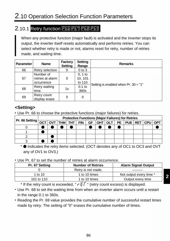
86
2
2.10 Operation Selection Function Parameters
2.10.1 Retry function
When any protective function (major fault) is activated and the inverter stops itsoutput, the inverter itself resets automatically and performs retries. You canselect whether retry is made or not, alarms reset for retry, number of retriesmade, and waiting time.
Parameter NameFactorySetting
SettingRange
Remarks
66 Retry selection 0 0 to 3
67Number ofretries at alarmoccurrence
00, 1 to10, 101to 110
68Retry waitingtime
1s0.1 to360s
69Retry countdisplay erase
0 0
Setting is enabled when Pr. 30 = "1"
<Setting>Use Pr. 66 to choose the protective functions (major failures) for retries.
Protective Functions (Major Failures) for RetriesPr. 66 Setting
OCT OVT THM THT FIN GF OHT OLT PE PUE RET CPU OPT0123
* Indicates the retry items selected. (OCT denotes any of OC1 to OC3 and OVTany of OV1 to OV3.)
Use Pr. 67 to set the number of retries at alarm occurrence.Pr. 67 Setting Number of Retries Alarm Signal Output
0 Retry is not made. ———1 to 10 1 to 10 times Not output every time *
101 to 110 1 to 10 times Output every time
* If the retry count is exceeded, " " (retry count excess) is displayed.Use Pr. 68 to set the waiting time from when an inverter alarm occurs until a restartin the range 0.1 to 360s.Reading the Pr. 69 value provides the cumulative number of successful restart timesmade by retry. The setting of "0" erases the cumulative number of times.
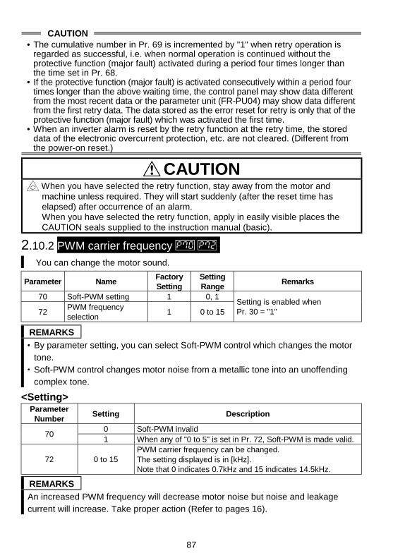
87
CAUTION• The cumulative number in Pr. 69 is incremented by "1" when retry operation is
regarded as successful, i.e. when normal operation is continued without theprotective function (major fault) activated during a period four times longer thanthe time set in Pr. 68.
• If the protective function (major fault) is activated consecutively within a period fourtimes longer than the above waiting time, the control panel may show data differentfrom the most recent data or the parameter unit (FR-PU04) may show data differentfrom the first retry data. The data stored as the error reset for retry is only that of theprotective function (major fault) which was activated the first time.
• When an inverter alarm is reset by the retry function at the retry time, the storeddata of the electronic overcurrent protection, etc. are not cleared. (Different fromthe power-on reset.)
CAUTION When you have selected the retry function, stay away from the motor andmachine unless required. They will start suddenly (after the reset time haselapsed) after occurrence of an alarm.When you have selected the retry function, apply in easily visible places theCAUTION seals supplied to the instruction manual (basic).
2.10.2 PWM carrier frequency You can change the motor sound.
Parameter NameFactorySetting
SettingRange
Remarks
70 Soft-PWM setting 1 0, 1
72PWM frequencyselection
1 0 to 15Setting is enabled whenPr. 30 = "1"
REMARKS
By parameter setting, you can select Soft-PWM control which changes the motortone.Soft-PWM control changes motor noise from a metallic tone into an unoffendingcomplex tone.
<Setting>Parameter
NumberSetting Description
0 Soft-PWM invalid70
1 When any of "0 to 5" is set in Pr. 72, Soft-PWM is made valid.
72 0 to 15PWM carrier frequency can be changed.The setting displayed is in [kHz].Note that 0 indicates 0.7kHz and 15 indicates 14.5kHz.
REMARKS
An increased PWM frequency will decrease motor noise but noise and leakagecurrent will increase. Take proper action (Refer to pages 16).
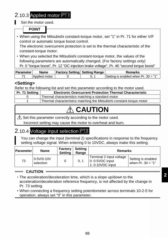
88
2
2.10.3 Applied motor Set the motor used.
POINT
When using the Mitsubishi constant-torque motor, set "1" in Pr. 71 for either V/Fcontrol or automatic torque boost control.The electronic overcurrent protection is set to the thermal characteristic of theconstant-torque motor.When you selected the Mitsubishi constant-torque motor, the values of thefollowing parameters are automatically changed. (For factory settings only)Pr. 0 "torque boost", Pr. 12 "DC injection brake voltage", Pr. 46 "second torque boost"
Parameter Name Factory Setting Setting Range Remarks71 Applied motor 0 0, 1 Setting is enabled when Pr. 30 = "1"
<Setting>Refer to the following list and set this parameter according to the motor used.Pr. 71 Setting Electronic Overcurrent Protection Thermal Characteristic
0 Thermal characteristics matching a standard motor1 Thermal characteristics matching the Mitsubishi constant-torque motor
CAUTION Set this parameter correctly according to the motor used.Incorrect setting may cause the motor to overheat and burn.
2.10.4 Voltage input selection You can change the input (terminal 2) specifications in response to the frequencysetting voltage signal. When entering 0 to 10VDC, always make this setting.
Parameter NameFactorySetting
SettingRange
Remarks
730-5V/0-10Vselection
0 0, 1Terminal 2 input voltage0: 0-5VDC input1: 0-10VDC input
Setting is enabledwhen Pr. 30 = "1"
CAUTION
The acceleration/deceleration time, which is a slope up/down to theacceleration/deceleration reference frequency, is not affected by the change inPr. 73 setting.When connecting a frequency setting potentiometer across terminals 10-2-5 foroperation, always set "0" in this parameter.
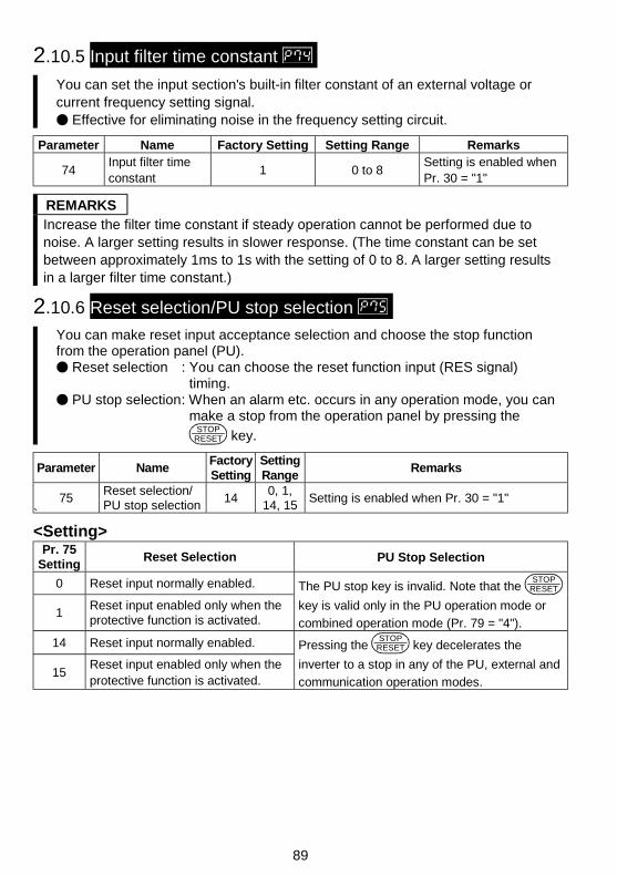
89
2.10.5 Input filter time constant
You can set the input section's built-in filter constant of an external voltage orcurrent frequency setting signal.
Effective for eliminating noise in the frequency setting circuit.
Parameter Name Factory Setting Setting Range Remarks
74Input filter timeconstant
1 0 to 8Setting is enabled whenPr. 30 = "1"
REMARKSIncrease the filter time constant if steady operation cannot be performed due tonoise. A larger setting results in slower response. (The time constant can be setbetween approximately 1ms to 1s with the setting of 0 to 8. A larger setting resultsin a larger filter time constant.)
2.10.6 Reset selection/PU stop selection
You can make reset input acceptance selection and choose the stop functionfrom the operation panel (PU).
Reset selection : You can choose the reset function input (RES signal)timing.
PU stop selection: When an alarm etc. occurs in any operation mode, you canmake a stop from the operation panel by pressing the
STOPRESET key.
Parameter NameFactorySetting
SettingRange
Remarks
75Reset selection/PU stop selection
140, 1,
14, 15Setting is enabled when Pr. 30 = "1"
`<Setting>
Pr. 75Setting
Reset Selection PU Stop Selection
0 Reset input normally enabled.
1Reset input enabled only when theprotective function is activated.
The PU stop key is invalid. Note that the STOP
RESET
key is valid only in the PU operation mode or
combined operation mode (Pr. 79 = "4").
14 Reset input normally enabled.
15Reset input enabled only when theprotective function is activated.
Pressing the STOP
RESET key decelerates the
inverter to a stop in any of the PU, external and
communication operation modes.
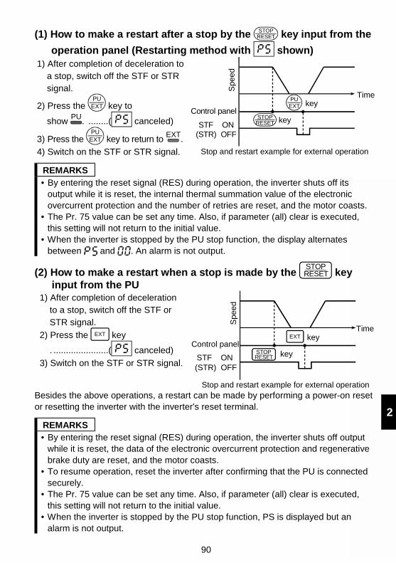
90
2
(1) How to make a restart after a stop by the STOPRESET key input from the
operation panel (Restarting method with shown)1) After completion of deceleration to
a stop, switch off the STF or STRsignal.
2) Press the PUEXT key to
show PU
. ........( canceled)
3) Press the PUEXT key to return to
EXT.
4) Switch on the STF or STR signal.
Spe
ed
Time key
Stop and restart example for external operation
Control panel key
PUEXT
STOPRESETSTF ON
(STR) OFF
REMARKS• By entering the reset signal (RES) during operation, the inverter shuts off its
output while it is reset, the internal thermal summation value of the electronicovercurrent protection and the number of retries are reset, and the motor coasts.
• The Pr. 75 value can be set any time. Also, if parameter (all) clear is executed,this setting will not return to the initial value.
• When the inverter is stopped by the PU stop function, the display alternatesbetween and . An alarm is not output.
(2) How to make a restart when a stop is made by the STOPRESET key
input from the PU1) After completion of deceleration
to a stop, switch off the STF orSTR signal.
2) Press the EXT key
. ......................( canceled)
3) Switch on the STF or STR signal.
Time key
keySTOPRESET
EXT
Spe
ed
Control panel
STF ON(STR) OFF
Stop and restart example for external operationBesides the above operations, a restart can be made by performing a power-on resetor resetting the inverter with the inverter's reset terminal.
REMARKS• By entering the reset signal (RES) during operation, the inverter shuts off output
while it is reset, the data of the electronic overcurrent protection and regenerativebrake duty are reset, and the motor coasts.
• To resume operation, reset the inverter after confirming that the PU is connectedsecurely.
• The Pr. 75 value can be set any time. Also, if parameter (all) clear is executed,this setting will not return to the initial value.
• When the inverter is stopped by the PU stop function, PS is displayed but analarm is not output.
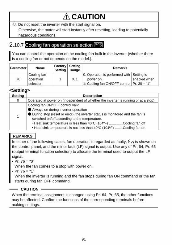
91
CAUTION Do not reset the inverter with the start signal on.Otherwise, the motor will start instantly after resetting, leading to potentiallyhazardous conditions.
2.10.7 Cooling fan operation selection
You can control the operation of the cooling fan built in the inverter (whether thereis a cooling fan or not depends on the model.).
Parameter NameFactorySetting
SettingRange
Remarks
76Cooling fanoperationselection
1 0, 10: Operation is performed with
power on.1: Cooling fan ON/OFF control
Setting isenabled whenPr. 30 = "1"
<Setting>Setting Description
0 Operated at power on (independent of whether the inverter is running or at a stop).
1
Cooling fan ON/OFF control valid
Always on during inverter operation
During stop (reset or error), the inverter status is monitored and the fan isswitched on/off according to the temperature. Heat sink temperature is less than 40ºC (104ºF) ..............Cooling fan off Heat sink temperature is not less than 40ºC (104ºF) ........Cooling fan on
REMARKS
In either of the following cases, fan operation is regarded as faulty, is shown onthe control panel, and the minor fault (LF) signal is output. Use any of Pr. 64, Pr. 65(output terminal function selection) to allocate the terminal used to output the LFsignal.
Pr. 76 = "0"When the fan comes to a stop with power on.Pr. 76 = "1"When the inverter is running and the fan stops during fan ON command or the fanstarts during fan OFF command.
CAUTION
When the terminal assignment is changed using Pr. 64, Pr. 65, the other functionsmay be affected. Confirm the functions of the corresponding terminals beforemaking settings.
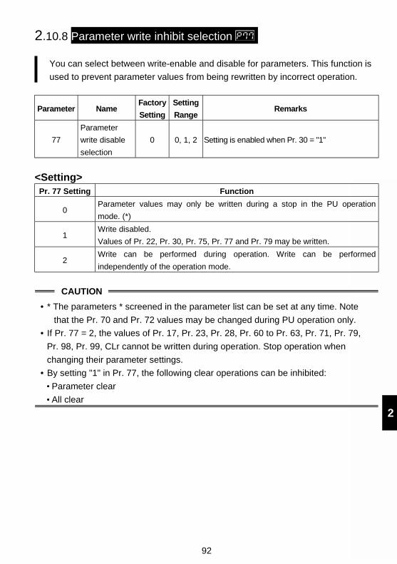
92
2
2.10.8 Parameter write inhibit selection
You can select between write-enable and disable for parameters. This function is
used to prevent parameter values from being rewritten by incorrect operation.
Parameter NameFactory
Setting
Setting
RangeRemarks
77
Parameter
write disable
selection
0 0, 1, 2 Setting is enabled when Pr. 30 = "1"
<Setting>Pr. 77 Setting Function
0Parameter values may only be written during a stop in the PU operation
mode. (*)
1Write disabled.
Values of Pr. 22, Pr. 30, Pr. 75, Pr. 77 and Pr. 79 may be written.
2Write can be performed during operation. Write can be performed
independently of the operation mode.
CAUTION
• * The parameters * screened in the parameter list can be set at any time. Note
that the Pr. 70 and Pr. 72 values may be changed during PU operation only.
• If Pr. 77 = 2, the values of Pr. 17, Pr. 23, Pr. 28, Pr. 60 to Pr. 63, Pr. 71, Pr. 79,
Pr. 98, Pr. 99, CLr cannot be written during operation. Stop operation when
changing their parameter settings.
• By setting "1" in Pr. 77, the following clear operations can be inhibited:
Parameter clear
All clear
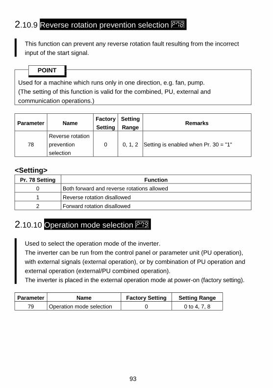
93
2.10.9 Reverse rotation prevention selection
This function can prevent any reverse rotation fault resulting from the incorrect
input of the start signal.
POINT
Used for a machine which runs only in one direction, e.g. fan, pump.
(The setting of this function is valid for the combined, PU, external and
communication operations.)
Parameter NameFactory
Setting
Setting
RangeRemarks
78
Reverse rotation
prevention
selection
0 0, 1, 2 Setting is enabled when Pr. 30 = "1"
<Setting>Pr. 78 Setting Function
0 Both forward and reverse rotations allowed
1 Reverse rotation disallowed
2 Forward rotation disallowed
2.10.10 Operation mode selection
Used to select the operation mode of the inverter.
The inverter can be run from the control panel or parameter unit (PU operation),
with external signals (external operation), or by combination of PU operation and
external operation (external/PU combined operation).
The inverter is placed in the external operation mode at power-on (factory setting).
Parameter Name Factory Setting Setting Range
79 Operation mode selection 0 0 to 4, 7, 8
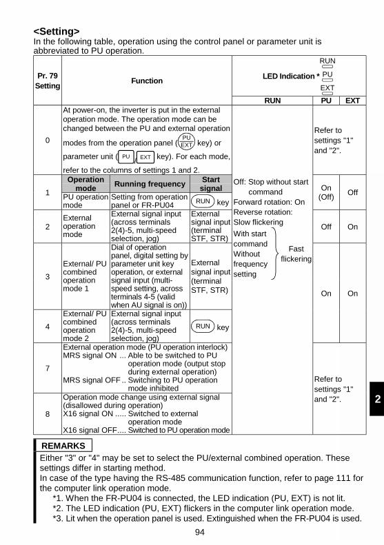
94
2
<Setting>In the following table, operation using the control panel or parameter unit isabbreviated to PU operation.
LED Indication *
RUN
PU
EXT
Pr. 79Setting
Function
RUN PU EXT
0
At power-on, the inverter is put in the externaloperation mode. The operation mode can bechanged between the PU and external operation
modes from the operation panel (PUEXT key) or
parameter unit ( PU/
EXT key). For each mode,
refer to the columns of settings 1 and 2.
Refer tosettings "1"and "2".
Operationmode
Running frequencyStart
signal1 PU operationmode
Setting from operationpanel or FR-PU04
RUN key
On(Off)
OffOff: Stop without start
commandForward rotation: OnReverse rotation:Slow flickering
2Externaloperationmode
External signal input(across terminals2(4)-5, multi-speedselection, jog)
Externalsignal input(terminalSTF, STR)
Off OnWith startcommandWithoutfrequencysetting
Fastflickering
3
External/ PUcombinedoperationmode 1
Dial of operationpanel, digital setting byparameter unit keyoperation, or externalsignal input (multi-speed setting, acrossterminals 4-5 (validwhen AU signal is on))
Externalsignal input(terminalSTF, STR)
4
External/ PUcombinedoperationmode 2
External signal input(across terminals2(4)-5, multi-speedselection, jog)
RUN key
On On
7
External operation mode (PU operation interlock)MRS signal ON ... Able to be switched to PU
operation mode (output stopduring external operation)
MRS signal OFF .. Switching to PU operationmode inhibited
8
Operation mode change using external signal(disallowed during operation)X16 signal ON ..... Switched to external
operation modeX16 signal OFF.... Switched to PU operation mode
Refer tosettings "1"and "2".
REMARKSEither "3" or "4" may be set to select the PU/external combined operation. Thesesettings differ in starting method.In case of the type having the RS-485 communication function, refer to page 111 forthe computer link operation mode.
*1. When the FR-PU04 is connected, the LED indication (PU, EXT) is not lit.*2. The LED indication (PU, EXT) flickers in the computer link operation mode.*3. Lit when the operation panel is used. Extinguished when the FR-PU04 is used.
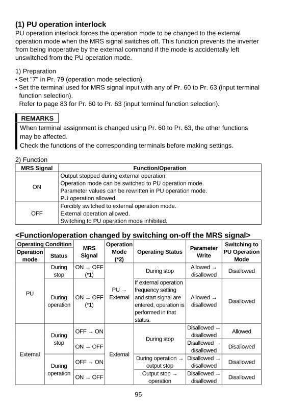
95
(1) PU operation interlockPU operation interlock forces the operation mode to be changed to the externaloperation mode when the MRS signal switches off. This function prevents the inverterfrom being inoperative by the external command if the mode is accidentally leftunswitched from the PU operation mode.
1) Preparation Set "7" in Pr. 79 (operation mode selection). Set the terminal used for MRS signal input with any of Pr. 60 to Pr. 63 (input terminalfunction selection).Refer to page 83 for Pr. 60 to Pr. 63 (input terminal function selection).
REMARKS
When terminal assignment is changed using Pr. 60 to Pr. 63, the other functionsmay be affected.Check the functions of the corresponding terminals before making settings.
2) FunctionMRS Signal Function/Operation
ON
Output stopped during external operation.Operation mode can be switched to PU operation mode.Parameter values can be rewritten in PU operation mode.PU operation allowed.
OFFForcibly switched to external operation mode.External operation allowed.Switching to PU operation mode inhibited.
<Function/operation changed by switching on-off the MRS signal>Operating ConditionOperation
modeStatus
MRSSignal
OperationMode(*2)
Operating StatusParameter
Write
Switching toPU Operation
ModeDuringstop
ON → OFF(*1)
During stopAllowed →disallowed
Disallowed
PUDuring
operationON → OFF
(*1)
PU →External
If external operationfrequency settingand start signal areentered, operation isperformed in thatstatus.
Allowed →disallowed
Disallowed
OFF → ONDisallowed →
disallowedAllowed
Duringstop
ON → OFFDuring stop
Disallowed →disallowed
Disallowed
OFF → ONDuring operation →
output stopDisallowed →
disallowedDisallowed
External
Duringoperation
ON → OFF
External
Output stop →operation
Disallowed →disallowed
Disallowed
96
2
REMARKS If the MRS signal is on, the operation mode cannot be switched to the PUoperation mode when the start signal (STF, STR) is on.
*1. The operation mode switches to the external operation mode independently ofwhether the start signal (STF, STR) is on or off.Therefore, the motor is run in the external operation mode when the MRS signalis switched off with either of STF and STR on.
*2. Switching the MRS signal on and rewriting the Pr. 79 value to other than "7" inthe PU operation mode causes the MRS signal to act as the ordinary MRSfunction (output stop). Also as soon as "7" is set in Pr. 79, the signal acts as thePU interlock signal.
(2) Operation mode switching by external signal1) Preparation
Set "8" (switching to other than external operation mode) in Pr. 79.Use any of Pr. 60 to Pr. 63 (input terminal function selection) to set the terminalused for X16 signal input.
REMARKSWhen terminal assignment is changed using Pr. 60 to Pr. 63, the other functionsmay be affected.Check the functions of the corresponding terminals before making settings.For details refer to page 83.
2) FunctionThis switching is enabled during an inverter stop only and cannot be achievedduring operation.X16 Signal Operation Mode
ON External operation mode (cannot be changed to the PU operation mode)OFF PU operation mode (cannot be changed to the external operation mode)
to Refer to to (page 56).
2.10.11 PID control to
The inverter can be used to exercise process control, e.g. flow rate, air volume orpressure.
The voltage input signal (0 to +5V or 0 to +10V) or Pr. 93 setting is used as aset point and the 4 to 20mA DC current input signal used as a feedback valueto constitute a feedback system for PID control.
POINT
Made valid by turning on the X14 signal. Use Pr. 60 to Pr. 63 (input terminalfunction selection) to make assignment.
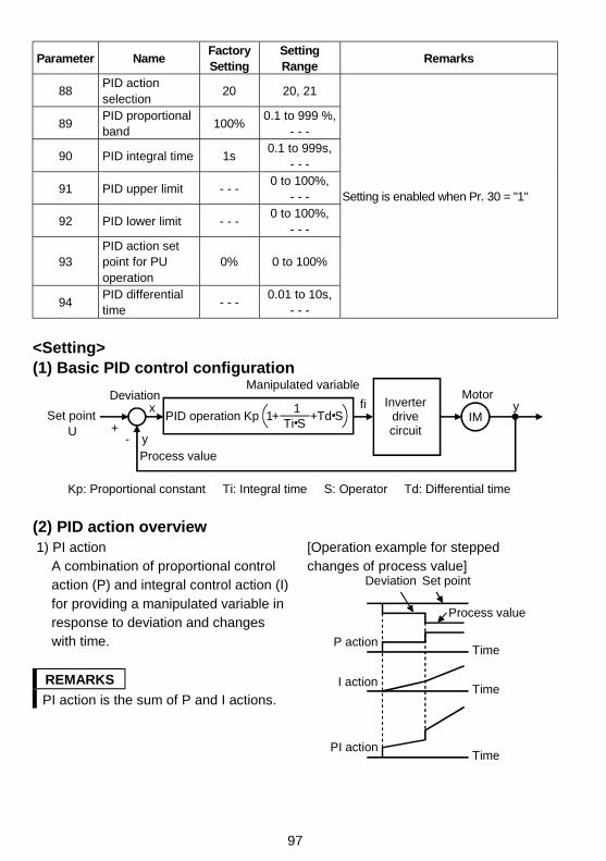
97
Parameter NameFactorySetting
SettingRange
Remarks
88PID actionselection
20 20, 21
89PID proportionalband
100%0.1 to 999 %,
- - -
90 PID integral time 1s0.1 to 999s,
- - -
91 PID upper limit - - -0 to 100%,
- - -
92 PID lower limit - - -0 to 100%,
- - -
93PID action setpoint for PUoperation
0% 0 to 100%
94PID differentialtime
- - -0.01 to 10s,
- - -
Setting is enabled when Pr. 30 = "1"
<Setting>(1) Basic PID control configuration
+
x
yProcess value
fi Inverter drive circuit
Motor
IMy
Kp : Proportional constant Ti : Integral time S : Operator Td : Differential time
-
Set pointU
Deviation
KpPID operationTi S
1+ +Td S1
Manipulated variable
(2) PID action overview1) PI action
A combination of proportional controlaction (P) and integral control action (I)for providing a manipulated variable inresponse to deviation and changeswith time.
REMARKS
PI action is the sum of P and I actions.
[Operation example for steppedchanges of process value]
Deviation Set point
Process value
Time
Time
TimePI action
I action
P action
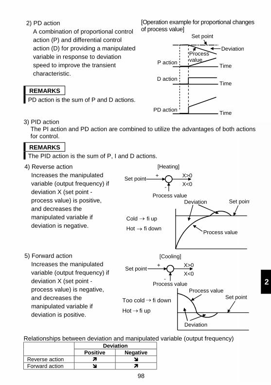
98
2
2) PD actionA combination of proportional controlaction (P) and differential controlaction (D) for providing a manipulatedvariable in response to deviationspeed to improve the transientcharacteristic.
REMARKS
PD action is the sum of P and D actions.
[Operation example for proportional changesof process value]
Deviation
Set point
Time
Time
TimePD action
D action
P action
Processvalue
3) PID actionThe PI action and PD action are combined to utilize the advantages of both actionsfor control.
REMARKS
The PID action is the sum of P, I and D actions.
4) Reverse actionIncreases the manipulatedvariable (output frequency) ifdeviation X (set point -process value) is positive,and decreases themanipulated variable ifdeviation is negative.
Set point
Process value
+
-
[Heating]
Deviation Set point
X>0
X<0
Cold fi up
Hot fi downProcess value
5) Forward actionIncreases the manipulatedvariable (output frequency) ifdeviation X (set point -process value) is negative,and decreases themanipulated variable ifdeviation is positive.
Set pointX>0
X<0
Process value
+
-
[Cooling]
Too cold fi down
Hot fi up
Set pointProcess value
Deviation
Relationships between deviation and manipulated variable (output frequency)Deviation
Positive NegativeReverse action ! "Forward action " !
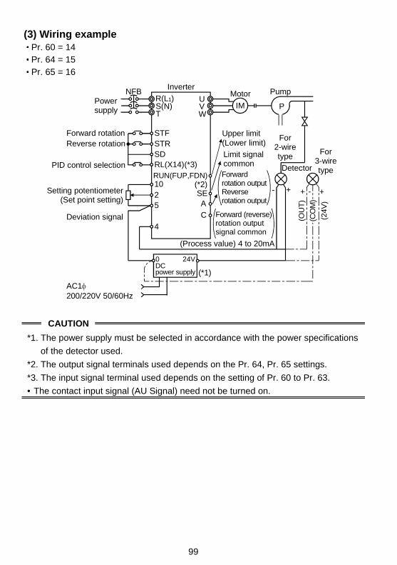
99
(3) Wiring example Pr. 60 = 14 Pr. 64 = 15 Pr. 65 = 16
Limit signal common
For 2-wire type
Detector
MotorPower supply
NFBInverter
0 24VDC power supply (*1)
R(L1)S(N)T
STFSTRSD
1025
4
UVW
SE
(Process value) 4 to 20mA
IM P
-+ + +-
(OU
T)
(24V
)A
C
RUN(FUP,FDN)PID control selection RL(X14)(*3)
(*2)
Forward rotationReverse rotation
Setting potentiometer(Set point setting)
Deviation signal
Pump
For 3-wire type
Upper limit(Lower limit)
Forward (reverse)rotation output signal common
Forward rotation outputReverse rotation output
AC1200/220V 50/60Hz
(CO
M)
CAUTION
*1. The power supply must be selected in accordance with the power specifications
of the detector used.
*2. The output signal terminals used depends on the Pr. 64, Pr. 65 settings.
*3. The input signal terminal used depends on the setting of Pr. 60 to Pr. 63.
• The contact input signal (AU Signal) need not be turned on.
100
2
(4) I/O signalsSignal Terminal Used Function Description
X14Depending on
Pr. 60 to Pr. 63
PID control
selectionTurn on X14 to exercise PID control.
2 2 Set point input Enter the set point for PID control.Input
4 4Process value
input
Enter the 4 to 20mADC process value
signal from the detector.
FUP Upper limit outputOutput to indicate that the process value
signal exceeded the upper limit value.
FDN Lower limit outputOutput to indicate that the process value
signal exceeded the lower limit value.Output
RL
Depending on
Pr. 64, Pr. 65Forward (reverse)
rotation direction
output
"Hi" is output to indicate that the output
indication of the parameter unit is forward
rotation (FWD) or "Low" to indicate that it is
reverse rotation (REV) or stop (STOP).
Enter the set point across inverter terminals 2-5 or in Pr. 93 and enter the processvalue signal across inverter terminals 4-5.To exercise PID control, turn on the X14 signal. When this signal is off, PID control isnot exercised.
Item Entry Description
Set 0V as 0% and 5V as 100%.When "0" is set in Pr. 73 (5V
selected for terminal 2).Set point
Across
terminals 2-5Set 0V as 0% and 10V as 100%.
When "1" is set in Pr. 73 (10V
selected for terminal 2).
Set point Pr. 93 Set the set point (%) in Pr. 93.
Process
value
Across
terminals 4-54mA DC is equivalent to 0% and 20mA DC to 100%.
(5) Parameter settingParameter
NumberName Setting Description
20 For heating, pressure control, etc. PID reverse action88
PID action
selection 21 For cooling, etc. PID forward action
0.1 to 999%
If the proportional band is narrow (parameter setting is
small), the manipulated variable varies greatly with a
slight change of the process value. Hence, as the
proportional band narrows, the response sensitivity
(gain) improves but the stability deteriorates, e.g.
hunting occurs.
Gain Kp = 1/proportional band
89
PID
proportional
band
- - - No proportional control
101
ParameterNumber
Name Setting Description
0.1 to 999s
Time required for the integral (I) action to provide thesame manipulated variable as that for the proportional(P) action. As the integral time decreases, the set pointis reached earlier but hunting occurs more easily.
90PID integral
time
- - - No integral control.
0 to 100%Set the upper limit. If the feedback value exceeds thesetting, the FUP signal is output. (Process value of4mA is equivalent to 0% and 20mA to 100%.)
91PID upper
limit- - - No function
0 to 100%
Set the lower limit. (If the process value goes out ofthe setting range, the FDN can be output. In this case,the process value of 4mA is equivalent to 0% and20mA to 100%.)
92PID lower
limit
- - - No function
93PID action
set point forPU operation
0 to 100%
Valid only when Pr. 79 = "3" (n9 = 0 for computer linkoperation) under the PU command in the PU operationor PU/external combined mode. (When the computerhas the speed command write in the computer linkoperation mode (NET))For external operation, the voltage across 2-5 is theset point.(C3 value is equivalent to 0% and C4 value to 100%.)
0.01 to 10s
Time required for the differential (D) action to providethe same process value as that for the proportional (P)action. As the differential time increases, greaterresponse is made to a deviation change.
94PID
differentialtime
- - - No differential control.
(6) Adjustment procedure
Turn on X14 signal.
Parameter setting
Terminal setting
Run
Adjust the PID control parameters, Pr. 88 to Pr. 94.
Set the I/O terminals and PID control terminals.(Use Pr. 64 and Pr. 65 (output terminal function selection) to set the FUP and FDN signals.)(Use any of Pr. 60 to Pr. 63 (input terminal function selection) to set the X14 signal.)
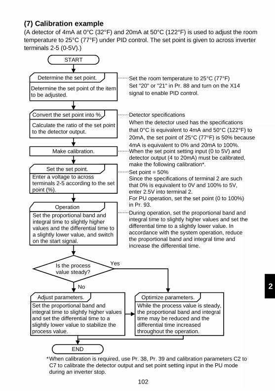
102
2
(7) Calibration example(A detector of 4mA at 0°C (32°F) and 20mA at 50°C (122°F) is used to adjust the roomtemperature to 25°C (77°F) under PID control. The set point is given to across inverterterminals 2-5 (0-5V).)
START
Is the process value steady?
Adjust parameters.
END
Yes
No
Set the room temperature to 25°C (77°F)Set "20" or "21" in Pr. 88 and turn on the X14 signal to enable PID control.
.......Determine the set point.
Determine the set point of the itemto be adjusted.
Convert the set point into %.
Calculate the ratio of the set pointto the detector output.
Make calibration.
Set the set point.Enter a voltage to across terminals 2-5 according to the setpoint (%).
Operation
Set the proportional band and integral time to slightly higher values and the differential time toa slightly lower value, and switchon the start signal.
Detector specificationsWhen the detector used has the specifications that 0°C is equivalent to 4mA and 50°C (122°F) to 20mA, the set point of 25°C (77°F) is 50% because 4mA is equivalent to 0% and 20mA to 100%.
.......
When the set point setting input (0 to 5V) and detector output (4 to 20mA) must be calibrated, make the following calibration*.
.......
.......
.......
Set the proportional band and integral time to slightly higher values and set the differential time to a slightly lower value to stabilize the process value.
Optimize parameters.
While the process value is steady,the proportional band and integraltime may be reduced and the differential time increased throughout the operation.
When calibration is required, use Pr. 38, Pr. 39 and calibration parameters C2 to C7 to calibrate the detector output and set point setting input in the PU mode during an inverter stop.
*
Set point = 50%Since the specifications of terminal 2 are suchthat 0% is equivalent to 0V and 100% to 5V,enter 2.5V into terminal 2.For PU operation, set the set point (0 to 100%)in Pr. 93.
During operation, set the proportional band andintegral time to slightly higher values and set thedifferential time to a slightly lower value. Inaccordance with the system operation, reducethe proportional band and integral time andincrease the differential time.
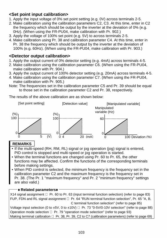
103
<Set point input calibration>1. Apply the input voltage of 0% set point setting (e.g. 0V) across terminals 2-5.2. Make calibration using the calibration parameters C2, C3. At this time, enter in C2
the frequency which should be output by the inverter at the deviation of 0% (e.g.0Hz). (When using the FR-PU04, make calibration with Pr. 902.)
3. Apply the voltage of 100% set point (e.g. 5V) to across terminals 2-5.4. Make calibration using Pr. 38 and calibration parameter C4. At this time, enter in
Pr. 38 the frequency which should be output by the inverter at the deviation of100% (e.g. 60Hz). (When using the FR-PU04, make calibration with Pr. 903.)
<Detector output calibration>1. Apply the output current of 0% detector setting (e.g. 4mA) across terminals 4-5.2. Make calibration using the calibration parameter C6. (When using the FR-PU04,
make calibration with Pr. 904.)3. Apply the output current of 100% detector setting (e.g. 20mA) across terminals 4-5.4. Make calibration using the calibration parameter C7. (When using the FR-PU04,
make calibration with Pr. 905.)Note: The frequencies set in the calibration parameter C5 and Pr. 39 should be equal
to those set in the calibration parameter C2 and Pr. 38, respectively.
The results of the above calibration are as shown below:
100
00 5 (V)
(%)
[Set point setting]
0
0 20 (mA)4
[Detection value]
(%)100
[Manipulated variable]
60
00 100 Deviation (%)
Manipulated variable (Hz)
REMARKS• If the multi-speed (RH, RM, RL) signal or jog operation (jog) signal is entered,
PID control is stopped and multi-speed or jog operation is started.• When the terminal functions are changed using Pr. 60 to Pr. 65, the other
functions may be affected. Confirm the functions of the corresponding terminalsbefore making settings.
• When PID control is selected, the minimum frequency is the frequency set in thecalibration parameter C2 and the maximum frequency is the frequency set inPr. 38. (The Pr. 1 "maximum frequency" and Pr. 2 "minimum frequency" settingsare also valid.)
♦♦♦♦ Related parameters♦♦♦♦X14 signal assignment ⇒ Pr. 60 to Pr. 63 (input terminal function selection) (refer to page 83)FUP, FDN and RL signal assignment ⇒ Pr. 64 "RUN terminal function selection", Pr. 65 "A, B,
C terminal function selection" (refer to page 85)Voltage input selection (0 to ±5V, 0 to ±10V) ⇒ Pr. 73 "0-5V/0-10V selection" (refer to page 88)Operation mode selection ⇒ Pr. 79 "operation mode selection" (refer to page 93)Making terminal calibration ⇒ Pr. 38, Pr. 39, C2 to C7 (calibration parameters) (refer to page 69)
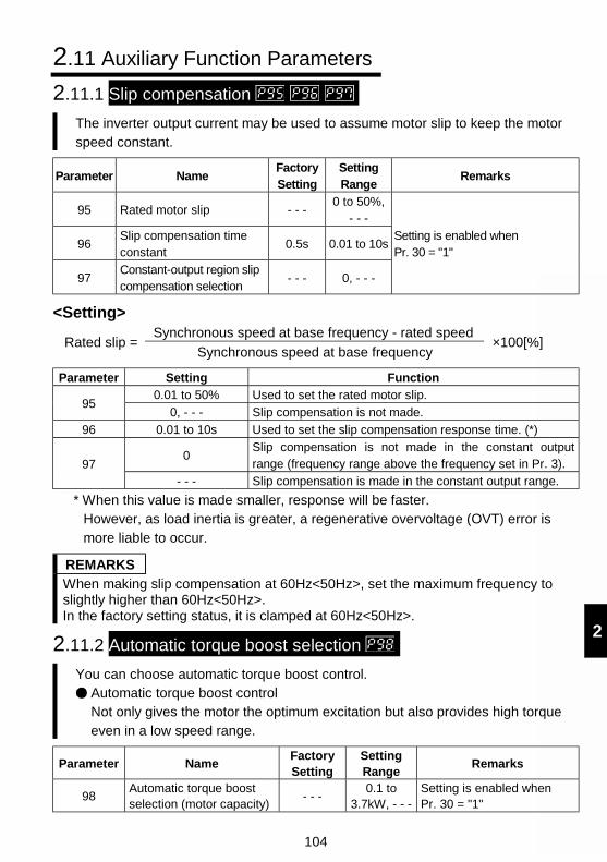
104
2
2.11 Auxiliary Function Parameters
2.11.1 Slip compensation
The inverter output current may be used to assume motor slip to keep the motorspeed constant.
Parameter NameFactorySetting
SettingRange
Remarks
95 Rated motor slip - - -0 to 50%,
- - -
96Slip compensation timeconstant
0.5s 0.01 to 10s
97Constant-output region slipcompensation selection
- - - 0, - - -
Setting is enabled whenPr. 30 = "1"
<Setting>Synchronous speed at base frequency - rated speed
Rated slip =Synchronous speed at base frequency
×100[%]
Parameter Setting Function0.01 to 50% Used to set the rated motor slip.
950, - - - Slip compensation is not made.
96 0.01 to 10s Used to set the slip compensation response time. (*)
0Slip compensation is not made in the constant outputrange (frequency range above the frequency set in Pr. 3).97
- - - Slip compensation is made in the constant output range.
* When this value is made smaller, response will be faster.However, as load inertia is greater, a regenerative overvoltage (OVT) error ismore liable to occur.
REMARKSWhen making slip compensation at 60Hz<50Hz>, set the maximum frequency toslightly higher than 60Hz<50Hz>.In the factory setting status, it is clamped at 60Hz<50Hz>.
2.11.2 Automatic torque boost selection
You can choose automatic torque boost control.Automatic torque boost controlNot only gives the motor the optimum excitation but also provides high torqueeven in a low speed range.
Parameter NameFactorySetting
SettingRange
Remarks
98Automatic torque boostselection (motor capacity)
- - -0.1 to
3.7kW, - - -Setting is enabled whenPr. 30 = "1"
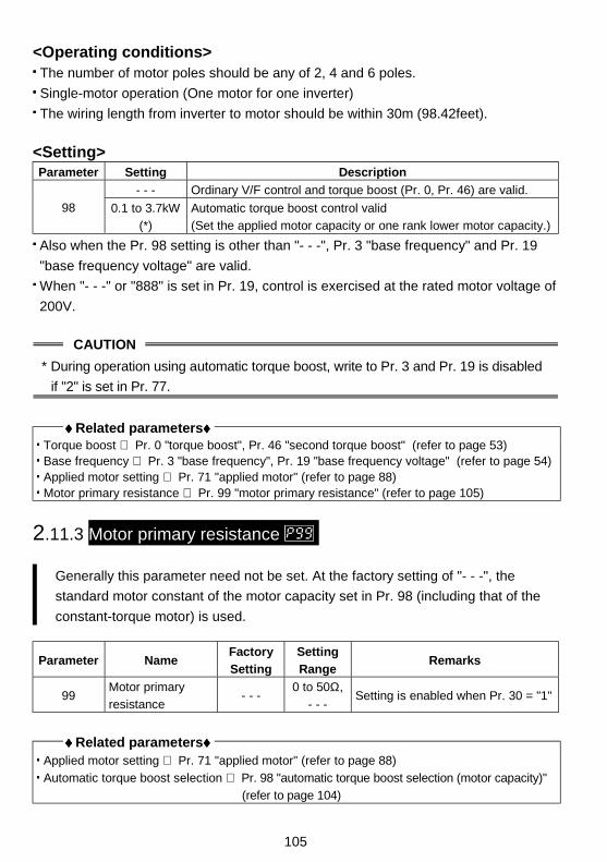
105
<Operating conditions> The number of motor poles should be any of 2, 4 and 6 poles.
Single-motor operation (One motor for one inverter)
The wiring length from inverter to motor should be within 30m (98.42feet).
<Setting>Parameter Setting Description
- - - Ordinary V/F control and torque boost (Pr. 0, Pr. 46) are valid.
98 0.1 to 3.7kW
(*)
Automatic torque boost control valid
(Set the applied motor capacity or one rank lower motor capacity.)
Also when the Pr. 98 setting is other than "- - -", Pr. 3 "base frequency" and Pr. 19
"base frequency voltage" are valid.
When "- - -" or "888" is set in Pr. 19, control is exercised at the rated motor voltage of
200V.
CAUTION
* During operation using automatic torque boost, write to Pr. 3 and Pr. 19 is disabled
if "2" is set in Pr. 77.
♦♦♦♦ Related parameters♦♦♦♦ Torque boost ⇒ Pr. 0 "torque boost", Pr. 46 "second torque boost" (refer to page 53) Base frequency ⇒ Pr. 3 "base frequency", Pr. 19 "base frequency voltage" (refer to page 54) Applied motor setting ⇒ Pr. 71 "applied motor" (refer to page 88) Motor primary resistance ⇒ Pr. 99 "motor primary resistance" (refer to page 105)
2.11.3 Motor primary resistance
Generally this parameter need not be set. At the factory setting of "- - -", the
standard motor constant of the motor capacity set in Pr. 98 (including that of the
constant-torque motor) is used.
Parameter NameFactory
Setting
Setting
RangeRemarks
99Motor primary
resistance- - -
0 to 50Ω,
- - -Setting is enabled when Pr. 30 = "1"
♦♦♦♦ Related parameters♦♦♦♦ Applied motor setting ⇒ Pr. 71 "applied motor" (refer to page 88)
Automatic torque boost selection ⇒ Pr. 98 "automatic torque boost selection (motor capacity)"
(refer to page 104)
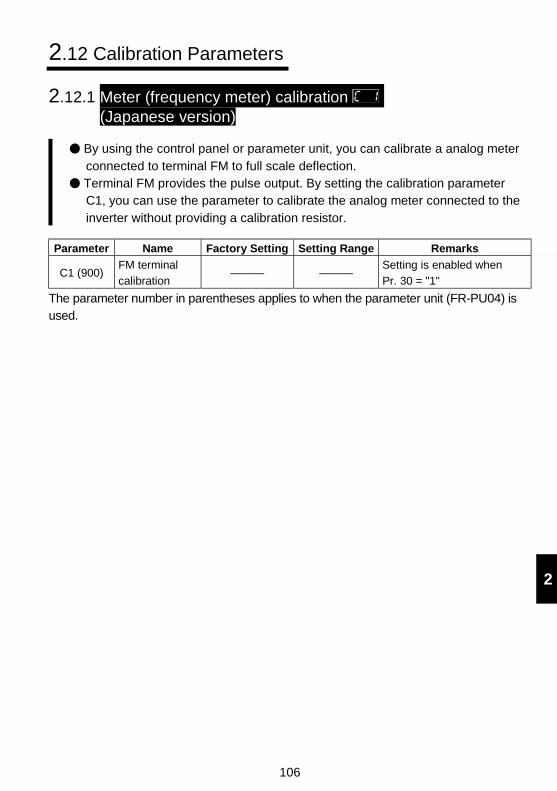
106
2
2.12 Calibration Parameters
2.12.1 Meter (frequency meter) calibration (Japanese version)
By using the control panel or parameter unit, you can calibrate a analog meterconnected to terminal FM to full scale deflection.
Terminal FM provides the pulse output. By setting the calibration parameterC1, you can use the parameter to calibrate the analog meter connected to theinverter without providing a calibration resistor.
Parameter Name Factory Setting Setting Range Remarks
C1 (900)FM terminal
calibration——— ———
Setting is enabled when
Pr. 30 = "1"
The parameter number in parentheses applies to when the parameter unit (FR-PU04) isused.
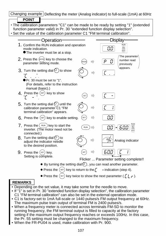
107
Changing example Deflecting the meter (Analog indicator) to full-scale (1mA) at 60Hz
POINT
The calibration parameters "C1" can be made to be ready by setting "1" (extendedfunction parameter valid) in Pr. 30 "extended function display selection".
Set the value of the calibration parameter C1 "FM terminal calibration".
(For details, refer to the instructionmanual (basic).)
MODE
5.
6. Press the key to enable setting. SETSET
RUN
PU
EXT
4.SET
9. SET
Flicker ... Parameter setting complete!!
SET
7. RUN
PU
EXT
RUNRUN
+
-
8.
2. MODE
Pr. 30 must be set to "1".
3. Turn the setting dial to show" " .
Operation Display1. Confirm the RUN indication and operation
mode indication.The inverter must be at a stop.
Press the key to show SET
" " .
The parameternumber read previously appears.
By turning the setting dial , you can read another parameter.
SETPress the key to return to the indication (step 4).
SETPress the key twice to show the next parameter ( ).
Press the key to choose theparameter setting mode.
Turn the setting dial until thecalibration parameter C1 "FMterminal calibration" appears.
Press the key to start theinverter. (The motor need not beconnected.)
Press the key.Setting is complete.
Turn the setting dial to adjust the indicator needle to the desired position.
Analog indicator
REMARKS• Depending on the set value, it may take some for the needle to move.• If "1" is set in Pr. 30 "extended function display selection", the calibration parameter
C1 "FM terminal calibration" can also be set in the external operation mode.• C1 is factory-set to 1mA full-scale or 1440 pulses/s FM output frequency at 60Hz.
The maximum pulse train output of terminal FM is 2400 pulses/s.• When a frequency meter is connected across terminals FM-SD to monitor the
running frequency, the FM terminal output is filled to capacity at the factorysetting if the maximum output frequency reaches or exceeds 100Hz. In this case,the Pr. 55 setting must be changed to the maximum frequency.
• When the FR-PU04 is used, make calibration with Pr. 900.
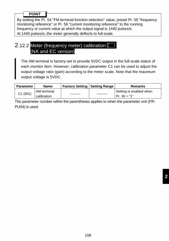
108
2
POINT
By setting the Pr. 54 "FM terminal function selection" value, preset Pr. 55 "frequencymonitoring reference" or Pr. 56 "current monitoring reference" to the runningfrequency or current value at which the output signal is 1440 pulses/s.At 1440 pulses/s, the meter generally deflects to full-scale.
2.12.2 Meter (frequency meter) calibration (NA and EC version)
The AM terminal is factory-set to provide 5VDC output in the full-scale status ofeach monitor item. However, calibration parameter C1 can be used to adjust theoutput voltage ratio (gain) according to the meter scale. Note that the maximumoutput voltage is 5VDC.
Parameter Name Factory Setting Setting Range Remarks
C1 (901)AM terminal
calibration——— ———
Setting is enabled when
Pr. 30 = "1"
The parameter number within the parentheses applies to when the parameter unit (FR-PU04) is used.
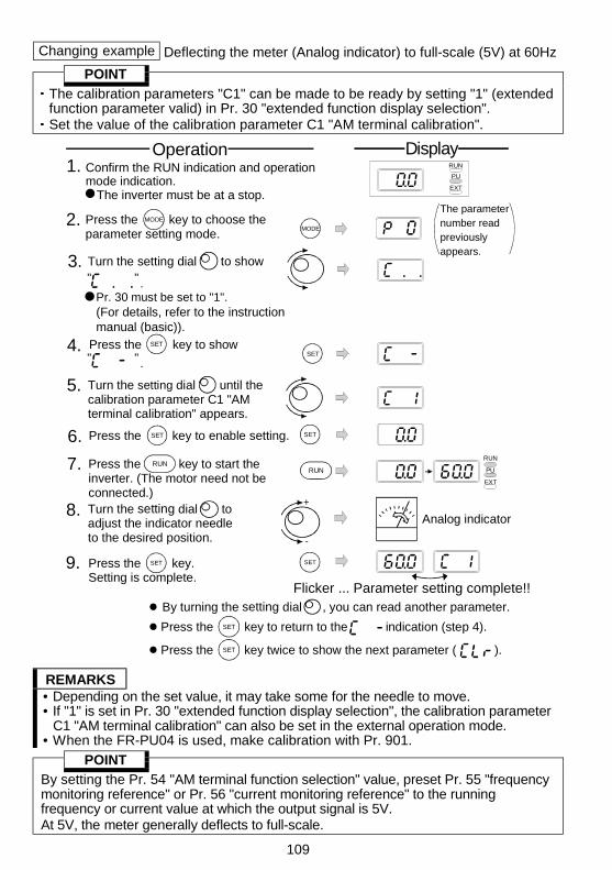
109
Changing example Deflecting the meter (Analog indicator) to full-scale (5V) at 60Hz
POINT
The calibration parameters "C1" can be made to be ready by setting "1" (extendedfunction parameter valid) in Pr. 30 "extended function display selection".Set the value of the calibration parameter C1 "AM terminal calibration".
MODE
5.
6. Press the key to enable setting. SETSET
RUN
PU
EXT
4.SET
9. SET
Flicker ... Parameter setting complete!!
SET
7. RUN
PU
EXT
RUNRUN
+
-
8.
2. MODE
Pr. 30 must be set to "1".
3. Turn the setting dial to show" " .
Operation Display1. Confirm the RUN indication and operation
mode indication.The inverter must be at a stop.
Press the key to show SET
" " .
The parameternumber read previously appears.
By turning the setting dial , you can read another parameter.
SETPress the key to return to the indication (step 4).
SETPress the key twice to show the next parameter ( ).
Press the key to choose theparameter setting mode.
Turn the setting dial until thecalibration parameter C1 "AMterminal calibration" appears.
Press the key to start theinverter. (The motor need not beconnected.)
Press the key.Setting is complete.
Turn the setting dial to adjust the indicator needle to the desired position.
(For details, refer to the instructionmanual (basic)).
Analog indicator
REMARKS• Depending on the set value, it may take some for the needle to move.• If "1" is set in Pr. 30 "extended function display selection", the calibration parameter
C1 "AM terminal calibration" can also be set in the external operation mode.• When the FR-PU04 is used, make calibration with Pr. 901.
POINT
By setting the Pr. 54 "AM terminal function selection" value, preset Pr. 55 "frequencymonitoring reference" or Pr. 56 "current monitoring reference" to the runningfrequency or current value at which the output signal is 5V.At 5V, the meter generally deflects to full-scale.
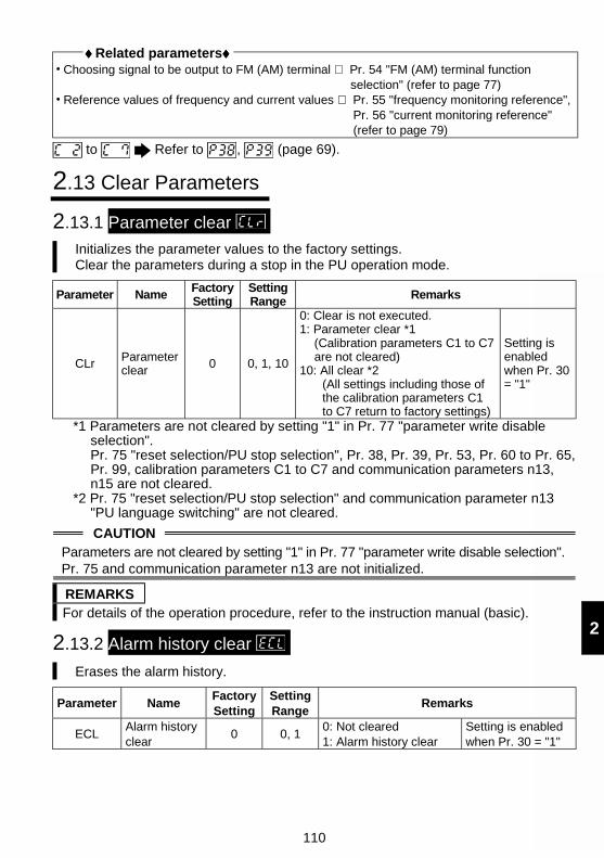
110
2
♦♦♦♦ Related parameters♦♦♦♦ Choosing signal to be output to FM (AM) terminal ⇒ Pr. 54 "FM (AM) terminal function
selection" (refer to page 77) Reference values of frequency and current values ⇒ Pr. 55 "frequency monitoring reference",
Pr. 56 "current monitoring reference"(refer to page 79)
to Refer to , (page 69).
2.13 Clear Parameters
2.13.1 Parameter clear Initializes the parameter values to the factory settings.Clear the parameters during a stop in the PU operation mode.
Parameter NameFactorySetting
SettingRange Remarks
CLr Parameterclear
0 0, 1, 10
0: Clear is not executed.1: Parameter clear *1
(Calibration parameters C1 to C7are not cleared)
10: All clear *2(All settings including those ofthe calibration parameters C1to C7 return to factory settings)
Setting isenabledwhen Pr. 30= "1"
*1 Parameters are not cleared by setting "1" in Pr. 77 "parameter write disableselection".Pr. 75 "reset selection/PU stop selection", Pr. 38, Pr. 39, Pr. 53, Pr. 60 to Pr. 65,Pr. 99, calibration parameters C1 to C7 and communication parameters n13,n15 are not cleared.
*2 Pr. 75 "reset selection/PU stop selection" and communication parameter n13"PU language switching" are not cleared.
CAUTIONParameters are not cleared by setting "1" in Pr. 77 "parameter write disable selection".Pr. 75 and communication parameter n13 are not initialized.
REMARKSFor details of the operation procedure, refer to the instruction manual (basic).
2.13.2 Alarm history clear
Erases the alarm history.
Parameter NameFactorySetting
SettingRange
Remarks
ECLAlarm historyclear
0 0, 10: Not cleared1: Alarm history clear
Setting is enabledwhen Pr. 30 = "1"
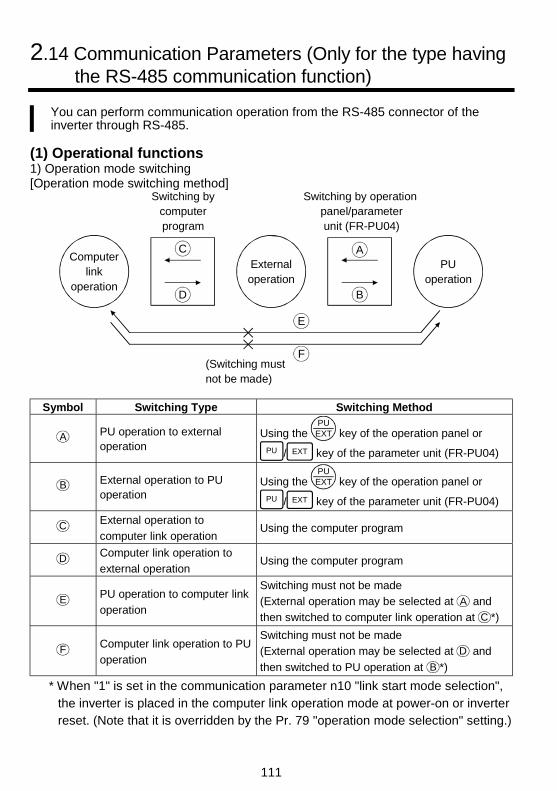
111
2.14 Communication Parameters (Only for the type havingthe RS-485 communication function)
You can perform communication operation from the RS-485 connector of theinverter through RS-485.
(1) Operational functions1) Operation mode switching[Operation mode switching method]
Computerlink
operation
Switching bycomputerprogram
Externaloperation
PUoperation
Switching by operation panel/parameter unit (FR-PU04)
(Switching mustnot be made)
C
D
E
F
B
A
Symbol Switching Type Switching Method
A PU operation to externaloperation
Using the PUEXT key of the operation panel or
PU / EXT key of the parameter unit (FR-PU04)
B External operation to PUoperation
Using the PUEXT key of the operation panel or
PU / EXT key of the parameter unit (FR-PU04)
C External operation to
computer link operationUsing the computer program
D Computer link operation to
external operationUsing the computer program
E PU operation to computer link
operation
Switching must not be made
(External operation may be selected at A and
then switched to computer link operation at C *)
F Computer link operation to PU
operation
Switching must not be made
(External operation may be selected at D and
then switched to PU operation at B *)
* When "1" is set in the communication parameter n10 "link start mode selection",the inverter is placed in the computer link operation mode at power-on or inverterreset. (Note that it is overridden by the Pr. 79 "operation mode selection" setting.)
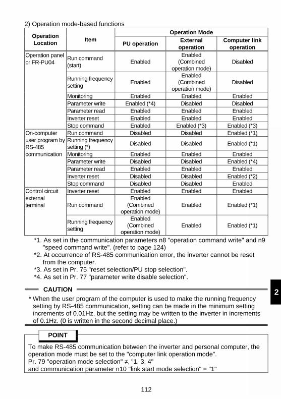
112
2
2) Operation mode-based functionsOperation Mode
OperationLocation
ItemPU operation
Externaloperation
Computer linkoperation
Run command(start)
EnabledEnabled
(Combinedoperation mode)
Disabled
Running frequencysetting
EnabledEnabled
(Combinedoperation mode)
Disabled
Monitoring Enabled Enabled EnabledParameter write Enabled (*4) Disabled DisabledParameter read Enabled Enabled EnabledInverter reset Enabled Enabled Enabled
Operation panelor FR-PU04
Stop command Enabled Enabled (*3) Enabled (*3)Run command Disabled Disabled Enabled (*1)Running frequencysetting (*)
Disabled Disabled Enabled (*1)
Monitoring Enabled Enabled EnabledParameter write Disabled Disabled Enabled (*4)Parameter read Enabled Enabled EnabledInverter reset Disabled Disabled Enabled (*2)
On-computeruser program byRS-485communication
Stop command Disabled Disabled EnabledInverter reset Enabled Enabled Enabled
Run commandEnabled
(Combinedoperation mode)
Enabled Enabled (*1)
Control circuitexternalterminal
Running frequencysetting
Enabled(Combined
operation mode)Enabled Enabled (*1)
*1. As set in the communication parameters n8 "operation command write" and n9"speed command write". (refer to page 124)
*2. At occurrence of RS-485 communication error, the inverter cannot be resetfrom the computer.
*3. As set in Pr. 75 "reset selection/PU stop selection".*4. As set in Pr. 77 "parameter write disable selection".
CAUTION
* When the user program of the computer is used to make the running frequencysetting by RS-485 communication, setting can be made in the minimum settingincrements of 0.01Hz, but the setting may be written to the inverter in incrementsof 0.1Hz. (0 is written in the second decimal place.)
POINT
To make RS-485 communication between the inverter and personal computer, theoperation mode must be set to the "computer link operation mode".Pr. 79 "operation mode selection" ≠‚ "1, 3, 4"and communication parameter n10 "link start mode selection" = "1"
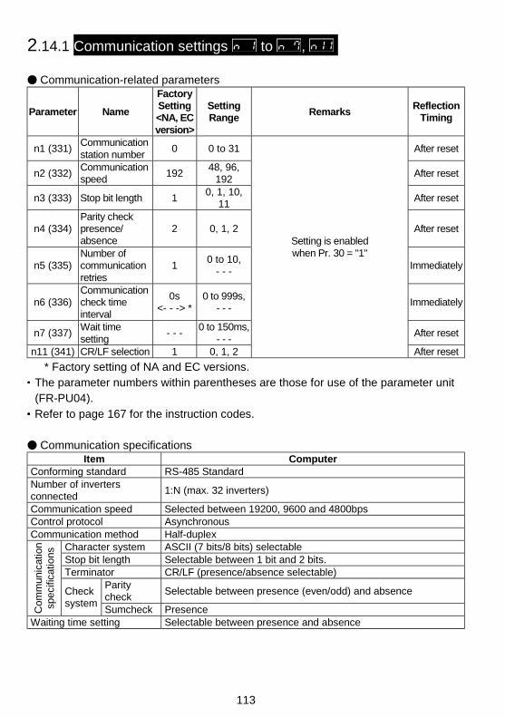
113
2.14.1 Communication settings to ,
Communication-related parameters
Parameter Name
FactorySetting<NA, ECversion>
SettingRange
RemarksReflection
Timing
n1 (331)Communicationstation number
0 0 to 31 After reset
n2 (332)Communicationspeed
19248, 96,
192After reset
n3 (333) Stop bit length 10, 1, 10,
11After reset
n4 (334)Parity checkpresence/absence
2 0, 1, 2 After reset
n5 (335)Number ofcommunicationretries
10 to 10,
- - -Immediately
n6 (336)Communicationcheck timeinterval
0s<- - -> *
0 to 999s,- - -
Immediately
n7 (337)Wait timesetting
- - -0 to 150ms,
- - -After reset
n11 (341) CR/LF selection 1 0, 1, 2
Setting is enabledwhen Pr. 30 = "1"
After reset
* Factory setting of NA and EC versions.The parameter numbers within parentheses are those for use of the parameter unit(FR-PU04).Refer to page 167 for the instruction codes.
Communication specificationsItem Computer
Conforming standard RS-485 StandardNumber of invertersconnected
1:N (max. 32 inverters)
Communication speed Selected between 19200, 9600 and 4800bpsControl protocol AsynchronousCommunication method Half-duplex
Character system ASCII (7 bits/8 bits) selectableStop bit length Selectable between 1 bit and 2 bits.Terminator CR/LF (presence/absence selectable)
Paritycheck
Selectable between presence (even/odd) and absence
Com
mun
icat
ion
spec
ifica
tions
Checksystem
Sumcheck PresenceWaiting time setting Selectable between presence and absence
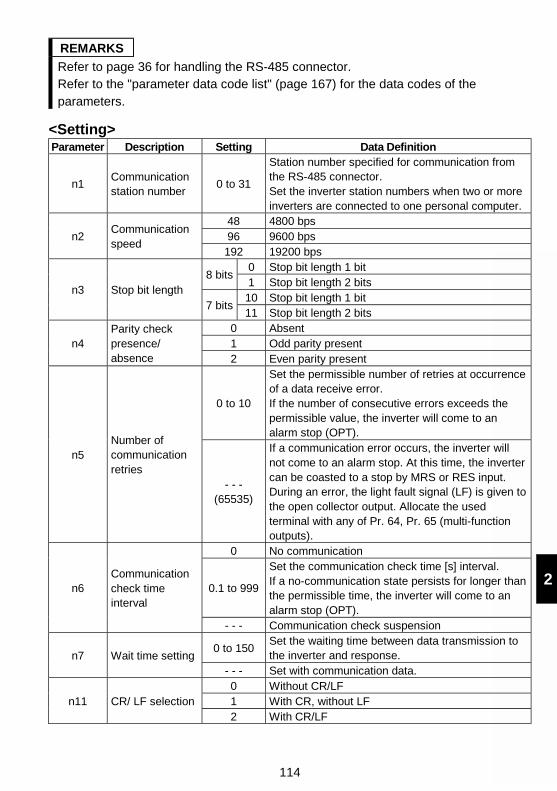
114
2
REMARKS
Refer to page 36 for handling the RS-485 connector.Refer to the "parameter data code list" (page 167) for the data codes of theparameters.
<Setting>Parameter Description Setting Data Definition
n1Communicationstation number
0 to 31
Station number specified for communication fromthe RS-485 connector.Set the inverter station numbers when two or moreinverters are connected to one personal computer.
48 4800 bps96 9600 bpsn2
Communicationspeed
192 19200 bps0 Stop bit length 1 bit
8 bits1 Stop bit length 2 bits
10 Stop bit length 1 bitn3 Stop bit length
7 bits11 Stop bit length 2 bits
0 Absent1 Odd parity presentn4
Parity checkpresence/absence 2 Even parity present
0 to 10
Set the permissible number of retries at occurrenceof a data receive error.If the number of consecutive errors exceeds thepermissible value, the inverter will come to analarm stop (OPT).
n5Number ofcommunicationretries
- - -(65535)
If a communication error occurs, the inverter willnot come to an alarm stop. At this time, the invertercan be coasted to a stop by MRS or RES input.During an error, the light fault signal (LF) is given tothe open collector output. Allocate the usedterminal with any of Pr. 64, Pr. 65 (multi-functionoutputs).
0 No communication
0.1 to 999
Set the communication check time [s] interval.If a no-communication state persists for longer thanthe permissible time, the inverter will come to analarm stop (OPT).
n6Communicationcheck timeinterval
- - - Communication check suspension
0 to 150Set the waiting time between data transmission tothe inverter and response.n7 Wait time setting
- - - Set with communication data.0 Without CR/LF1 With CR, without LFn11 CR/ LF selection2 With CR/LF
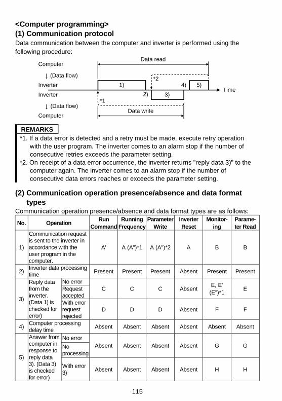
115
<Computer programming>(1) Communication protocolData communication between the computer and inverter is performed using thefollowing procedure:
Data read
Data write
1) 5)4)
3)2)*1
*2
Computer
(Data flow)
Inverter
Computer
(Data flow)
InverterTime
REMARKS*1. If a data error is detected and a retry must be made, execute retry operation
with the user program. The inverter comes to an alarm stop if the number ofconsecutive retries exceeds the parameter setting.
*2. On receipt of a data error occurrence, the inverter returns "reply data 3)" to thecomputer again. The inverter comes to an alarm stop if the number ofconsecutive data errors reaches or exceeds the parameter setting.
(2) Communication operation presence/absence and data formattypes
Communication operation presence/absence and data format types are as follows:
No. OperationRun
CommandRunning
FrequencyParameter
WriteInverterReset
Monitor-ing
Parame-ter Read
1)
Communication requestis sent to the inverter inaccordance with theuser program in thecomputer.
A' A (A")*1 A (A")*2 A B B
2)Inverter data processingtime
Present Present Present Absent Present Present
No errorRequestaccepted
C C C AbsentE, E'
(E")*1E
3)
Reply datafrom theinverter.(Data 1) ischecked forerror)
With errorrequestrejected
D D D Absent F F
4)Computer processingdelay time
Absent Absent Absent Absent Absent Absent
No error
Noprocessing
Absent Absent Absent Absent G G
5)
Answer fromcomputer inresponse toreply data3). (Data 3)is checkedfor error)
With error3)
Absent Absent Absent Absent H H
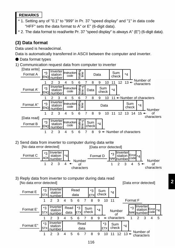
116
2
REMARKS
* 1. Setting any of "0.1" to "999" in Pr. 37 "speed display" and "1" in data code"HFF" sets the data format to A" or E" (6-digit data).
* 2. The data format to read/write Pr. 37 "speed display" is always A" (E") (6-digit data).
(3) Data formatData used is hexadecimal.Data is automatically transferred in ASCII between the computer and inverter.
Data format types1) Communication request data from computer to inverter
1 2 3 4 5 6 7 8 9 10 11 12 13 14 15
Format A
Format A'
Format A"
[Data write]
[Data read]
Format B
Number of characters
Number of characters
*3ENQ
Inverterstationnumber
Instructioncode
Wai
ting
time
Data *4Number
of characters
Sumcheck
Number of characters
1 2 3 4 5 6 7 8 9 10 11
*3ENQ
Inverterstationnumber
Instructioncode
Wai
ting
time Data *4Sum
check
1 2 3 4 5 6 7 8 9 10 11 12 13
*3ENQ
Inverterstationnumber
Instructioncode
Wai
ting
time
Data *4Sumcheck
*5
1 2 3 4 5 6 7 8 9
*3ENQ
Inverterstationnumber
Instructioncode
Wai
ting
time *4Sum
check
*5
2) Send data from inverter to computer during data write
Errorcode
Inverterstationnumber
*3ACK
*4
Number of
characters
Format CInverterstationnumber Number
of characters
*3NAK
*4Format D
[No data error detected] [Data error detected]
1 2 3 4 1 2 3 4 5
3) Reply data from inverter to computer during data read
Format E''
Format E'
*3ETX
Number of
characters
Format F
*3STX
[Data error detected][No data error detected]
Readdata
Number of characters1 2 3 4 5 6 7 8 9 10 11 12 13
Inverterstationnumber
*4Sumcheck
Format E *3STX
*3ETX
Readdata
1 2 3 4 5 6 7 8 9 10 11
Inverterstationnumber
*4Sumcheck
Errorcode
Inverterstationnumber
*3NAK
*4
1 2 3 4 5
*3STX
*3ETX
Readdata
1 2 3 4 5 6 7 8 9
Inverterstationnumber
*4Sumcheck
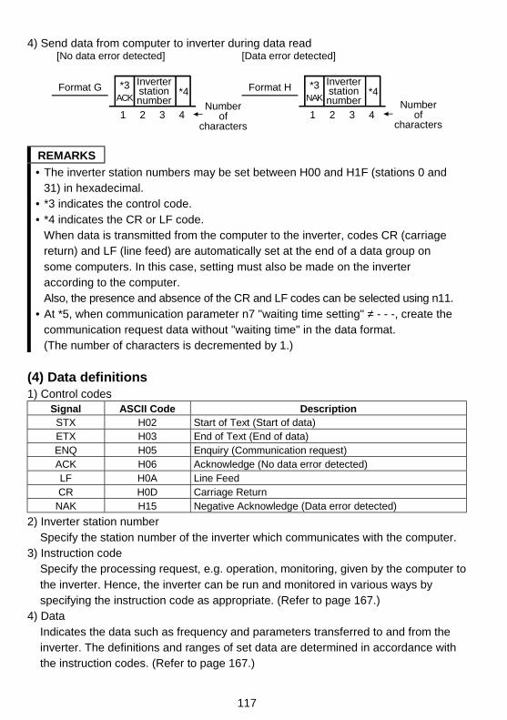
117
4) Send data from computer to inverter during data read
*3ACK
*4
Number of
characters
Inverterstationnumber
1 2 3 4
Format G Format H
[No data error detected] [Data error detected]
Number of
characters
*3NAK
*4Inverterstationnumber
1 2 3 4
REMARKS
• The inverter station numbers may be set between H00 and H1F (stations 0 and31) in hexadecimal.
• *3 indicates the control code.• *4 indicates the CR or LF code.
When data is transmitted from the computer to the inverter, codes CR (carriagereturn) and LF (line feed) are automatically set at the end of a data group onsome computers. In this case, setting must also be made on the inverteraccording to the computer.Also, the presence and absence of the CR and LF codes can be selected using n11.
• At *5, when communication parameter n7 "waiting time setting" ≠ - - -, create thecommunication request data without "waiting time" in the data format.(The number of characters is decremented by 1.)
(4) Data definitions1) Control codes
Signal ASCII Code DescriptionSTX H02 Start of Text (Start of data)ETX H03 End of Text (End of data)ENQ H05 Enquiry (Communication request)ACK H06 Acknowledge (No data error detected)LF H0A Line FeedCR H0D Carriage Return
NAK H15 Negative Acknowledge (Data error detected)
2) Inverter station numberSpecify the station number of the inverter which communicates with the computer.
3) Instruction codeSpecify the processing request, e.g. operation, monitoring, given by the computer tothe inverter. Hence, the inverter can be run and monitored in various ways byspecifying the instruction code as appropriate. (Refer to page 167.)
4) DataIndicates the data such as frequency and parameters transferred to and from theinverter. The definitions and ranges of set data are determined in accordance withthe instruction codes. (Refer to page 167.)
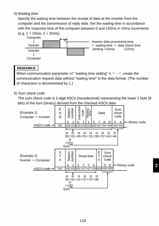
118
2
5) Waiting timeSpecify the waiting time between the receipt of data at the inverter from thecomputer and the transmission of reply data. Set the waiting time in accordancewith the response time of the computer between 0 and 150ms in 10ms increments(e.g. 1 = 10ms, 2 = 20ms).
Computer
Inverter
Inverter
Computer
Inverter data processing time = waiting time + data check time(setting 10ms) (12ms)
REMARKS
When communication parameter n7 "waiting time setting" ≠‚ "- - -", create thecommunication request data without "waiting time" in the data format. (The numberof characters is decremented by 1.)
6) Sum check codeThe sum check code is 2-digit ASCII (hexadecimal) representing the lower 1 byte (8bits) of the sum (binary) derived from the checked ASCII data.
ENQ
10 1 E 1 0 7 A D F 4H05 H30 H31 H31H45 H31 H30 H37 H41 H44 H46 H34
STX
0 1 1 7 0 3 0H02 H30 H31 H37H31 H37 H30 H03 H33 H30
ETX
7
Sum checkcode
Sum checkcode
Binary code
(Example 1)Computer Inverter
ASCII code
(Example 2)Inverter Computer
ASCII codeBinary code
H1F4=
H30
H31
H45
H31
H31
H30
H37
H41
H44+ + + + + + + +
H130=
H30
H31
H31
H37
H37
H30+ + + + +
Sum
Sum
Sta
tion
n
umbe
r
Read time
Sta
tion
n
umbe
r
Data
Wa
itin
g
time
Inst
ruct
ion
code
119
7) Error code
If any error is found in the data received by the inverter, its definition is sent back to
the computer together with the NAK code. (Refer to page 122.)
REMARKS
1. When the data from the computer has an error, the inverter will not accept that
data.
2. Any data communication, e.g. run command, monitoring, is started when the
computer gives a communication request. Without the computer's command, the
inverter does not return any data. For monitoring, therefore, design the program
to cause the computer to provide a data read request as required.
3. When accessing the parameter settings, data for link parameter expansion
setting differs between the parameters as indicated below:Instruction
CodeData
Read H7FLink
parameter
expansion
setting Write HFF
H00: Pr. 0 to Pr. 99 can be accessed.
H01: Calibration parameters C1 to C7 (Pr. 900 to
Pr. 905) and communication parameter n13
(Pr. 145) can be accessed.
H03: Communication parameters n1 to n12
(Pr. 331 to Pr. 342) can be accessed.
H09: Communication parameters n14 to n17
(Pr. 990 to Pr. 993) can be accessed.
CAUTION When the inverter's permissible communication time interval is not set,interlocks are provided to disable operation to prevent hazardous conditions.Always set the communication check time interval before starting operation.
Data communication is not started automatically but is made only once whenthe computer provides a communication request. If communication is disabledduring operation due to signal cable breakage etc, the inverter cannot bestopped. When the communication check time interval has elapsed, the inverterwill come to an alarm stop (OPT).The inverter can be coasted to a stop by switching on its RES signal or byswitching power off.
If communication is broken due to signal cable breakage, computer fault etc, theinverter does not detect such a fault. This should be fully noted.
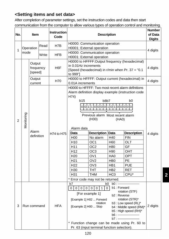
120
2
<Setting items and set data>After completion of parameter settings, set the instruction codes and data then startcommunication from the computer to allow various types of operation control and monitoring.
No. ItemInstruction
CodeDescription
Numberof DataDigits
Read H7BH0000: Communication operationH0001: External operation
1Operationmode
Write HFBH0000: Communication operationH0001: External operation
4 digits
Outputfrequency[speed]
H6F
H0000 to HFFFF:Output frequency (hexadecimal)in 0.01Hz increments[Speed (hexadecimal) in r/min when Pr. 37 = "0.1to 999"]
4 digits
Outputcurrent
H70H0000 to HFFFF: Output current (hexadecimal) in0.01A increments
4 digits
H0000 to HFFFF: Two most recent alarm definitionsAlarm definition display example (instruction codeH74)
b15 b8b7 b0
0 0 1 1 0 0 0 0 0 0 0 0 00 1 1
Previous alarm(H30)
Most recent alarm(HA0)
Alarm dataData Description Data DescriptionH00 No alarm H40 FINH10 OC1 H60 OLTH11 OC2 H80 GFH12 OC3 H90 OHTH20 OV1 HA0 OPTH21 OV2 HB0 PEH22 OV3 HB1 PUEH30 THT HB2 RETH31 THM HC0 CPU*
2
Mon
itori
ng
Alarmdefinition
H74 to H75
* Error code may not be returned.
4 digits
3 Run command HFA
b0 : b1 : Forward rotation (STF)b2 : Reverse rotation (STR)*b3 : Low speed (RL)*b4 : Middle speed (RM)*b5 : High speed (RH)*b6 : b7 :
b70 0 0 0 0 0 01
b0
[For example 1]
[Example 1] H02 ... Forward rotation[Example 2] H00 ... Stop
* Function change can be made using Pr. 60 toPr. 63 (input terminal function selection).
2 digits
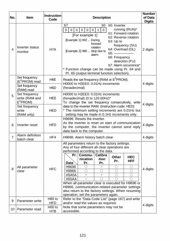
121
No. Item InstructionCode
DescriptionNumberof DataDigits
4Inverter statusmonitor
H7A
b7
0 0 0 0 0 0 01
b0
[For example 1][Example 1] H02 ... During forward rotation[Example 2] H80 ... Stop due to alarm
b0: Inverter running (RUN)*b1: Forward rotationb2: Reverse rotation b3: Up to frequency (SU)b4: Overload (OL)b5: b6: Frequency detection (FU)b7: Alarm occurrence*
* Function change can be made using Pr. 64 andPr. 65 (output terminal function selection).
2 digits
Set frequency(E2PROM) read
H6E
Set frequency(RAM) read
H6D
Reads the set frequency (RAM or E2PROM).H0000 to H2EE0: 0.01Hz increments(hexadecimal)
4 digits
Set frequencywrite (RAM andE2PROM)
HEE5
Set frequencywrite(RAM only)
HED
H0000 to H2EE0: 0.01Hz increments(hexadecimal) (0 to 120.00Hz)*To change the set frequency consecutively, writedata to the inverter RAM. (Instruction code: HED)* The minimum setting increments are 0.01Hz but
setting may be made in 0.1Hz increments only.
4 digits
6 Inverter reset HFD
H9696: Resets the inverter.As the inverter is reset on start of communicationby the computer, the inverter cannot send replydata back to the computer.
4 digits
7Alarm definitionbatch clear
HF4 H9696: Alarm history batch clear 4 digits
All parameters return to the factory settings.Any of four different all clear operations areperformed according to the data.
Pr.
Data
Commu-nication
Pr.
Calibra-tionPr.
OtherPr.
HECHFF
H9696H9966H5A5AH55AA
8 All parameterclear
HFC
When all parameter clear is executed for H9696 orH9966, communication-related parameter settingsalso return to the factory settings. When resumingoperation, set the parameters again.
4 digits
9 Parameter writeH80 toHFD
10 Parameter readH00 toH7B
Refer to the "Data Code List" (page 167) and writeand/or read the values as required.Note that some parameters may not beaccessible.
4 digits
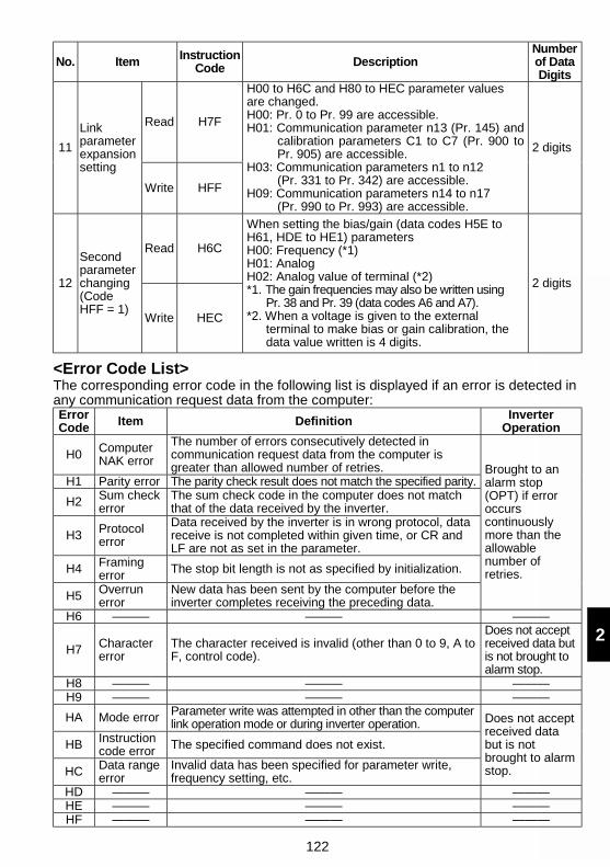
122
2
No. Item InstructionCode Description
Numberof DataDigits
Read H7F
11
Linkparameterexpansionsetting
Write HFF
H00 to H6C and H80 to HEC parameter valuesare changed.H00: Pr. 0 to Pr. 99 are accessible.H01: Communication parameter n13 (Pr. 145) and
calibration parameters C1 to C7 (Pr. 900 toPr. 905) are accessible.
H03: Communication parameters n1 to n12(Pr. 331 to Pr. 342) are accessible.
H09: Communication parameters n14 to n17(Pr. 990 to Pr. 993) are accessible.
2 digits
Read H6C
12
Secondparameterchanging(CodeHFF = 1)
Write HEC
When setting the bias/gain (data codes H5E toH61, HDE to HE1) parametersH00: Frequency (*1)H01: AnalogH02: Analog value of terminal (*2)*1. The gain frequencies may also be written using
Pr. 38 and Pr. 39 (data codes A6 and A7).*2. When a voltage is given to the external
terminal to make bias or gain calibration, thedata value written is 4 digits.
2 digits
<Error Code List>The corresponding error code in the following list is displayed if an error is detected inany communication request data from the computer:ErrorCode Item Definition Inverter
Operation
H0 ComputerNAK error
The number of errors consecutively detected incommunication request data from the computer isgreater than allowed number of retries.
H1 Parity error The parity check result does not match the specified parity.
H2 Sum checkerror
The sum check code in the computer does not matchthat of the data received by the inverter.
H3 Protocolerror
Data received by the inverter is in wrong protocol, datareceive is not completed within given time, or CR andLF are not as set in the parameter.
H4 Framingerror The stop bit length is not as specified by initialization.
H5 Overrunerror
New data has been sent by the computer before theinverter completes receiving the preceding data.
Brought to analarm stop(OPT) if erroroccurscontinuouslymore than theallowablenumber ofretries.
H6 ——— ——— ———
H7 Charactererror
The character received is invalid (other than 0 to 9, A toF, control code).
Does not acceptreceived data butis not brought toalarm stop.
H8 ——— ——— ———H9 ——— ——— ———
HA Mode error Parameter write was attempted in other than the computerlink operation mode or during inverter operation.
HB Instructioncode error The specified command does not exist.
HC Data rangeerror
Invalid data has been specified for parameter write,frequency setting, etc.
Does not acceptreceived databut is notbrought to alarmstop.
HD ——— ——— ———HE ——— ——— ———HF ——— ——— ———
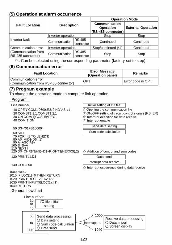
123
(5) Operation at alarm occurrenceOperation Mode
Fault Location Description CommunicationOperation
(RS-485 connector)External Operation
Inverter operation Stop StopInverter fault
CommunicationRS-485connector
Continued Continued
Inverter operation Stop/continued (*4) ContinuedCommunication error(Communication fromRS-485 connector) Communication
RS-485connector Stop Stop
*4: Can be selected using the corresponding parameter (factory-set to stop).
(6) Communication error
Fault LocationError Message
(Operation panel) Remarks
Communication error(Communication from RS-485 connector)
OPT Error code is OPT
(7) Program exampleTo change the operation mode to computer link operation
Program
1000 *REC1010 IF LOC(1)=0 THEN RETURN1020 PRINT"RECEIVE DATA"
1040 RETURN
140 GOTO 50Interrupt data receive
1030 PRINT INPUT$(LOC(1),#1)
130 PRINT#1,D$ Data send
Initial setting of I/O fileLine number
Interrupt occurrence during data receive
30 ON COM(1)GOSUB*REC 20 COMST1,1,1:COMST1,2,1 10 OPEN"COM1:9600,E,8,2,HD"AS #1 Opening the communication file
40 COM(1)ON
50 D$="01FB10000" Send data setting
Sum code calculation
80 A$=MID$(D$,I,1) 90 A=ASC(A$)
100 S=S+A 110 NEXT I
70 FOR I=1 TO LEN(D$) 60 S=0
Addition of control and sum codes 120 D$=CHR$(&H5)+D$+RIGHT$(HEX$(S),2)
ON/OFF setting of circuit control signals (RS, ER)
Interrupt enableInterrupt definition for data receive
General flowchart
Data import
50
140 Data send
10
40
to to
Line numberI/O file initial
settingto
1000
1040
InterruptReceive data processing
Screen display Sum code calculation
Send data processing Data setting
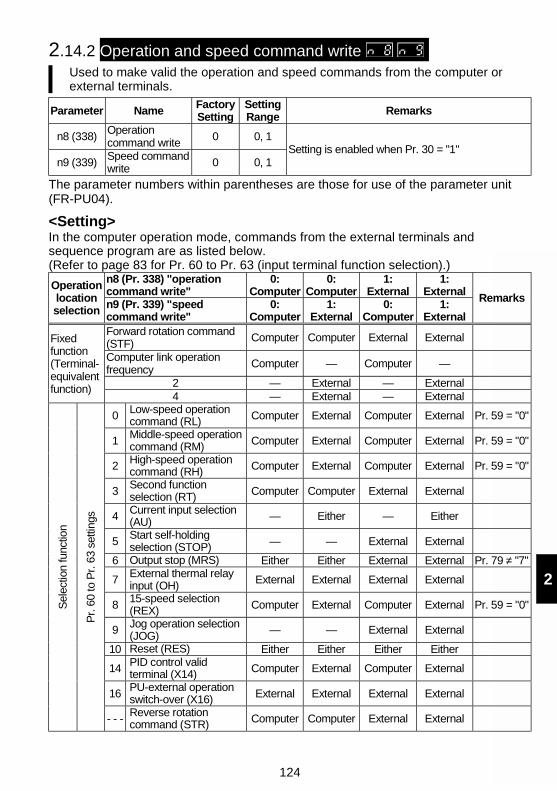
124
2
2.14.2 Operation and speed command write Used to make valid the operation and speed commands from the computer orexternal terminals.
Parameter NameFactorySetting
SettingRange Remarks
n8 (338)Operationcommand write
0 0, 1
n9 (339)Speed commandwrite 0 0, 1
Setting is enabled when Pr. 30 = "1"
The parameter numbers within parentheses are those for use of the parameter unit(FR-PU04).
<Setting>In the computer operation mode, commands from the external terminals andsequence program are as listed below.(Refer to page 83 for Pr. 60 to Pr. 63 (input terminal function selection).)
n8 (Pr. 338) "operationcommand write"
0:Computer
0:Computer
1:External
1:ExternalOperation
locationselection n9 (Pr. 339) "speed
command write"0:
Computer1:
External0:
Computer1:
External
Remarks
Forward rotation command(STF)
Computer Computer External External
Computer link operationfrequency Computer — Computer —
2 — External — External
Fixedfunction(Terminal-equivalentfunction)
4 — External — External
0 Low-speed operationcommand (RL) Computer External Computer External Pr. 59 = "0"
1Middle-speed operationcommand (RM) Computer External Computer External Pr. 59 = "0"
2 High-speed operationcommand (RH) Computer External Computer External Pr. 59 = "0"
3Second functionselection (RT) Computer Computer External External
4 Current input selection(AU) — Either — Either
5Start self-holdingselection (STOP) — — External External
6 Output stop (MRS) Either Either External External Pr. 79 ≠ "7"
7 External thermal relayinput (OH) External External External External
815-speed selection(REX) Computer External Computer External Pr. 59 = "0"
9 Jog operation selection(JOG) — — External External
10 Reset (RES) Either Either Either Either
14 PID control validterminal (X14) Computer External Computer External
16PU-external operationswitch-over (X16) External External External External
Sel
ectio
n fu
nctio
n
Pr.
60
to P
r. 6
3 se
tting
s
- - - Reverse rotationcommand (STR) Computer Computer External External
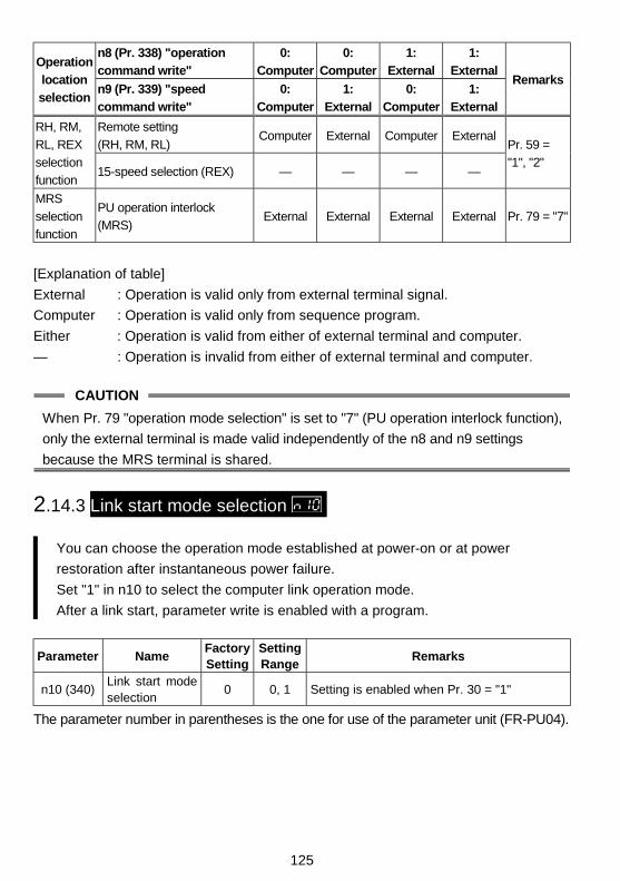
125
n8 (Pr. 338) "operation
command write"
0:
Computer
0:
Computer
1:
External
1:
ExternalOperation
location
selectionn9 (Pr. 339) "speed
command write"
0:
Computer
1:
External
0:
Computer
1:
External
Remarks
Remote setting
(RH, RM, RL)Computer External Computer External
RH, RM,
RL, REX
selection
function15-speed selection (REX) — — — —
Pr. 59 =
"1", "2"
MRS
selection
function
PU operation interlock
(MRS)External External External External Pr. 79 = "7"
[Explanation of table]
External : Operation is valid only from external terminal signal.
Computer : Operation is valid only from sequence program.
Either : Operation is valid from either of external terminal and computer.
— : Operation is invalid from either of external terminal and computer.
CAUTION
When Pr. 79 "operation mode selection" is set to "7" (PU operation interlock function),
only the external terminal is made valid independently of the n8 and n9 settings
because the MRS terminal is shared.
2.14.3 Link start mode selection
You can choose the operation mode established at power-on or at power
restoration after instantaneous power failure.
Set "1" in n10 to select the computer link operation mode.
After a link start, parameter write is enabled with a program.
Parameter NameFactorySetting
SettingRange
Remarks
n10 (340)Link start modeselection
0 0, 1 Setting is enabled when Pr. 30 = "1"
The parameter number in parentheses is the one for use of the parameter unit (FR-PU04).
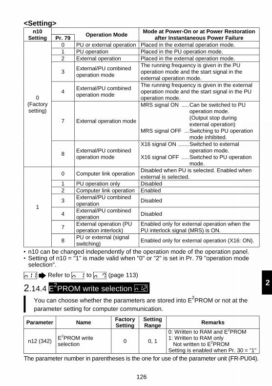
126
2
<Setting>n10
Setting Pr. 79Operation Mode
Mode at Power-On or at Power Restorationafter Instantaneous Power Failure
0 PU or external operation Placed in the external operation mode.1 PU operation Placed in the PU operation mode.2 External operation Placed in the external operation mode.
3External/PU combinedoperation mode
The running frequency is given in the PUoperation mode and the start signal in theexternal operation mode.
4External/PU combinedoperation mode
The running frequency is given in the externaloperation mode and the start signal in the PUoperation mode.
7 External operation mode
MRS signal ON .....Can be switched to PUoperation mode.(Output stop duringexternal operation)
MRS signal OFF ...Switching to PU operationmode inhibited.
0(Factorysetting)
8External/PU combinedoperation mode
X16 signal ON .......Switched to externaloperation mode.
X16 signal OFF .....Switched to PU operationmode.
0 Computer link operationDisabled when PU is selected. Enabled whenexternal is selected.
1 PU operation only Disabled2 Computer link operation Enabled
3External/PU combinedoperation
Disabled
4External/PU combinedoperation
Disabled
7External operation (PUoperation interlock)
Enabled only for external operation when thePU interlock signal (MRS) is ON.
1
8PU or external (signalswitching)
Enabled only for external operation (X16: ON).
n10 can be changed independently of the operation mode of the operation panel.Setting of n10 = "1" is made valid when "0" or "2" is set in Pr. 79 "operation modeselection".
Refer to to (page 113)
2.14.4 E2PROM write selection You can choose whether the parameters are stored into E2PROM or not at theparameter setting for computer communication.
Parameter NameFactorySetting
SettingRange Remarks
n12 (342)E2PROM writeselection 0 0, 1
0: Written to RAM and E2PROM1: Written to RAM only
Not written to E2PROMSetting is enabled when Pr. 30 = "1"
The parameter number in parentheses is the one for use of the parameter unit (FR-PU04).
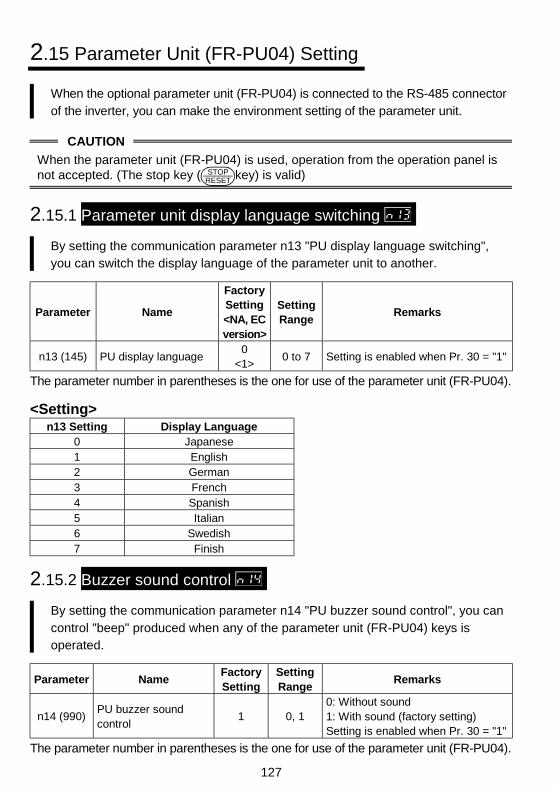
127
2.15 Parameter Unit (FR-PU04) Setting
When the optional parameter unit (FR-PU04) is connected to the RS-485 connectorof the inverter, you can make the environment setting of the parameter unit.
CAUTION
When the parameter unit (FR-PU04) is used, operation from the operation panel isnot accepted. (The stop key ( STOP
RESET key) is valid)
2.15.1 Parameter unit display language switching
By setting the communication parameter n13 "PU display language switching",you can switch the display language of the parameter unit to another.
Parameter Name
FactorySetting<NA, ECversion>
SettingRange
Remarks
n13 (145) PU display language0
<1>0 to 7 Setting is enabled when Pr. 30 = "1"
The parameter number in parentheses is the one for use of the parameter unit (FR-PU04).
<Setting>n13 Setting Display Language
0 Japanese1 English2 German3 French4 Spanish5 Italian6 Swedish7 Finish
2.15.2 Buzzer sound control
By setting the communication parameter n14 "PU buzzer sound control", you cancontrol "beep" produced when any of the parameter unit (FR-PU04) keys isoperated.
Parameter NameFactorySetting
SettingRange
Remarks
n14 (990)PU buzzer soundcontrol
1 0, 10: Without sound1: With sound (factory setting)Setting is enabled when Pr. 30 = "1"
The parameter number in parentheses is the one for use of the parameter unit (FR-PU04).
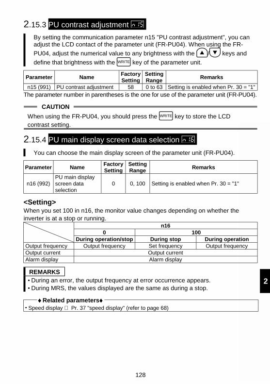
128
2
2.15.3 PU contrast adjustment
By setting the communication parameter n15 "PU contrast adjustment", you canadjust the LCD contact of the parameter unit (FR-PU04). When using the FR-
PU04, adjust the numerical value to any brightness with the / keys and
define that brightness with the WRITE key of the parameter unit.
Parameter NameFactorySetting
SettingRange
Remarks
n15 (991) PU contrast adjustment 58 0 to 63 Setting is enabled when Pr. 30 = "1"
The parameter number in parentheses is the one for use of the parameter unit (FR-PU04).
CAUTION
When using the FR-PU04, you should press the WRITE key to store the LCDcontrast setting.
2.15.4 PU main display screen data selection
You can choose the main display screen of the parameter unit (FR-PU04).
Parameter NameFactorySetting
SettingRange
Remarks
n16 (992)PU main displayscreen dataselection
0 0, 100 Setting is enabled when Pr. 30 = "1"
<Setting>When you set 100 in n16, the monitor value changes depending on whether theinverter is at a stop or running.
n160 100
During operation/stop During stop During operationOutput frequency Output frequency Set frequency Output frequencyOutput current Output currentAlarm display Alarm display
REMARKS During an error, the output frequency at error occurrence appears. During MRS, the values displayed are the same as during a stop.
♦♦♦♦ Related parameters♦♦♦♦ Speed display ⇒ Pr. 37 "speed display" (refer to page 68)
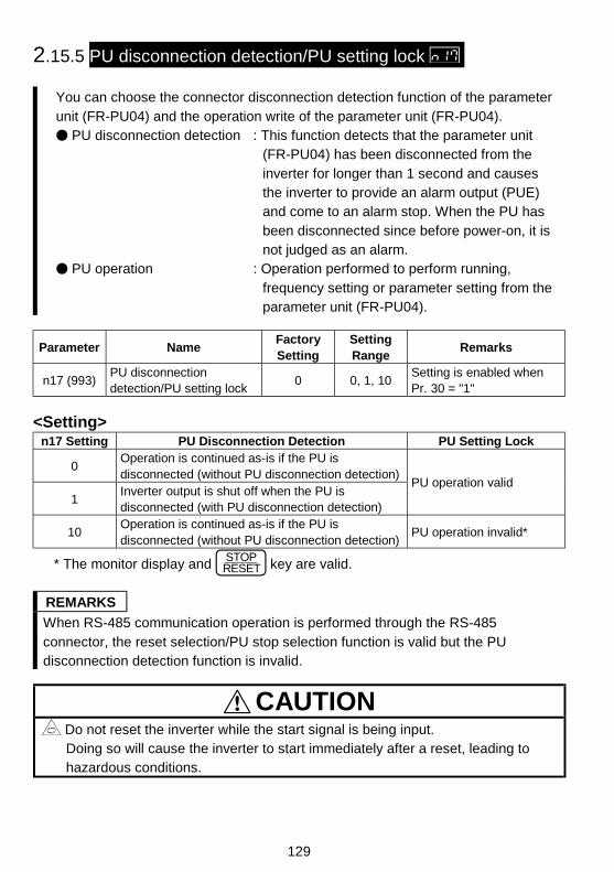
129
2.15.5 PU disconnection detection/PU setting lock
You can choose the connector disconnection detection function of the parameterunit (FR-PU04) and the operation write of the parameter unit (FR-PU04).
PU disconnection detection : This function detects that the parameter unit(FR-PU04) has been disconnected from theinverter for longer than 1 second and causesthe inverter to provide an alarm output (PUE)and come to an alarm stop. When the PU hasbeen disconnected since before power-on, it isnot judged as an alarm.
PU operation : Operation performed to perform running,frequency setting or parameter setting from theparameter unit (FR-PU04).
Parameter NameFactorySetting
SettingRange
Remarks
n17 (993)PU disconnectiondetection/PU setting lock
0 0, 1, 10Setting is enabled whenPr. 30 = "1"
<Setting>n17 Setting PU Disconnection Detection PU Setting Lock
0Operation is continued as-is if the PU isdisconnected (without PU disconnection detection)
1Inverter output is shut off when the PU isdisconnected (with PU disconnection detection)
PU operation valid
10Operation is continued as-is if the PU isdisconnected (without PU disconnection detection)
PU operation invalid*
* The monitor display and STOPRESET key are valid.
REMARKS
When RS-485 communication operation is performed through the RS-485connector, the reset selection/PU stop selection function is valid but the PUdisconnection detection function is invalid.
CAUTION Do not reset the inverter while the start signal is being input.Doing so will cause the inverter to start immediately after a reset, leading tohazardous conditions.
130
3
This chapter explains the "protective functions" of thisproduct.Always read the instructions before using the equipment.
3.1 Errors (Alarms) ....................................................1313.2 Troubleshooting ...................................................1403.3 Precautions for Maintenance and Inspection .......143
3.PROTECTIVEFUNCTIONS
Chapter 1
Chapter 2
Chapter 3
Chapter 4
131
3.1 Errors (Alarms)
If any fault has occurred in the inverter, the corresponding protective function isactivated to bring the inverter to an alarm stop and automatically give thecorresponding error (alarm) indication on the PU display.If your fault does not correspond to any of the following errors or if you have any otherproblem, please contact your sales representative.
Retention of alarm output signal ..... When the magnetic contactor (MC) provided onthe power supply side of the inverter is openedat the activation of the protective function, theinverter's control power will be lost and thealarm output will not be held.
Alarm indication .............................. When the protective function is activated, theoperation panel display automatically switchesto the above indication.
Resetting method............................ When the protective function is activated, theinverter output is kept stopped. Unless reset,therefore, the inverter cannot restart. Switchpower off once, then on again; power off once,then on again; or apply RES signal for morethan 0.1 second. Kept on, "Err." appears(flickers) to indicate that the inverter is beingreset.
When the protective function is activated, take the corresponding corrective action,then reset the inverter, and resume operation.
3.1.1 Error (alarm) definitions
(1) Major failures
Operation Panel Indication OC1 FR-PU04 OC During Acc
Name Overcurrent cut-off during acceleration
Description
When the inverter output current reaches or exceedsapproximately 200% of the rated inverter current duringacceleration, the protective circuit is activated to stop the inverteroutput.
Check pointCheck for sudden acceleration.Check for output short-circuit/ground fault.
Corrective action Increase the acceleration time.
132
3
Operation Panel Indication OC2 FR-PU04 Stedy Spd OC
Name Overcurrent cut-off during constant speed
Description
When the inverter output current reaches or exceedsapproximately 200% of the rated inverter current during constant-speed operation, the protective circuit is activated to stop theinverter output.
Check pointCheck for sudden load change.Check for output short-circuit/ground fault.
Corrective action Keep load stable.
Operation Panel Indication OC3 FR-PU04 OC During Dec
Name Overcurrent cut-off during deceleration
Description
When the inverter output current reaches or exceedsapproximately 200% of the rated inverter current duringdeceleration (other than acceleration or constant speed), theprotective circuit is activated to stop the inverter output.
Check pointCheck for sudden speed reduction.Check for output short-circuit/ground fault.Check for too fast operation of motor's mechanical brake.
Corrective actionIncrease the deceleration time.Adjust brake operation.
Operation Panel Indication OV1 FR-PU04 OV During Acc
Name Regenerative overvoltage cut-off during acceleration
Description
When the main circuit DC voltage in the inverter rises to or abovethe specified value due to excessive regenerative energy duringacceleration, the protective circuit is activated to stop the inverteroutput. The circuit may also be activated by a surge voltageproduced in the power supply system.
Check point Check for too slow acceleration.
Corrective action Decrease the acceleration time. Install a power factor improving reactor.
Operation Panel Indication OV2 FR-PU04 Stedy Spd OV
Name Regenerative overvoltage cut-off during constant speed
Description
When the main circuit DC voltage in the inverter rises to or abovethe specified value due to excessive regenerative energy duringconstant speed, the protective circuit is activated to stop theinverter output. The circuit may also be activated by a surgevoltage produced in the power supply system.
Check point Check for sudden load change.
Corrective action Keep load stable. Install a power factor improving reactor.
133
Operation Panel Indication OV3 FR-PU04 OV During Dec
Name Regenerative overvoltage cut-off during deceleration or stop
Description
When the main circuit DC voltage in the inverter rises to or abovethe specified value due to excessive regenerative energy duringdeceleration or stop, the protective circuit is activated to stop theinverter output. The circuit may also be activated by a surgevoltage produced in the power supply system.
Check point Check for sudden speed reduction.
Corrective action
Increase the deceleration time. (Set the deceleration time whichmatches the inertia moment of the load)
Decrease the braking duty. Install a power factor improving reactor.
Operation Panel Indication THM FR-PU04 Motor Overload
NameMotor overload cut-off (electronic thermal overcurrent protection)(* 1)
Description
The electronic overcurrent protection in the inverter detects motoroverheat due to overload or reduced cooling capability during low-speed operation to stop the inverter output. When a multi-polemotor or two or more motors are run, provide a thermal relay inthe output side of the inverter.
Check point Check the motor for use under overload.
Corrective actionReduce the load weight.For the constant-torque motor, change the Pr. 71 setting to theconstant-torque motor setting.
Operation Panel Indication THT FR-PU04 Inv. Overload
NameInverter overload cut-off (electronic thermal overcurrent protection)(* 1)
Description
If a current of more than 150% of the rated output current flowsand overcurrent shut-off does not occur (200% or less), inverse-time characteristics cause the electronic overcurrent protection tobe activated to stop the inverter output in order to protect theoutput transistors.
Check point Check the motor for use under overload.Corrective action Reduce the load weight.
*1. Resetting the inverter initializes the internal heat integrating data of theelectronic overcurrent protection.
Operation Panel Indication FIN FR-PU04 H/Sink O/Temp
Name Fin overheat
DescriptionIf the cooling fin overheats, the overheat sensor is actuated tostop the inverter output.
Check point Check for too high ambient temperature. Check for cooling fin clogging.
Corrective action Set the ambient temperature to within the specifications.
134
3
Operation Panel Indication GF FR-PU04 Ground Fault
Name Start-time output side ground fault overcurrent protection
Description
This function stops the inverter output if a ground fault overcurrentflows due to a ground fault which occurred in the inverter's output(load) side. Made valid when Pr. 40 "start-time ground faultdetection selection" = "1".
Check point Check for a ground fault in the motor and connection cable.Corrective action Remedy the ground fault portion.
Operation Panel Indication OHT FR-PU04 OH Fault
Name External thermal relay (*2)
Description
If the external thermal relay designed for motor overheatprotection or the internally mounted temperature relay in themotor switches on (contacts open), the inverter output is stopped.If the relay contacts are reset automatically, the inverter will notrestart unless it is reset.
Check pointCheck for motor overheating.Check that the value of 7 (OH signal) is set correctly in any ofPr. 60 to Pr. 63 (input terminal function selection).
Corrective action Reduce the load and operating duty.
*2. Functions only when any of Pr. 60 to Pr. 63 (input terminal function selection) isset to OH.
Operation Panel Indication OLT FR-PU04 Stll Prev STP
Name Stall prevention (overload)
DescriptionThe running frequency has fallen to 0 by stall preventionoperation activated. OL appears while stall prevention is beingactivated.
Check point Check the motor for use under overload.Corrective action Reduce the load weight.
Operation Panel Indication OPT FR-PU04 Option Fault
Name Communication error (*3)
DescriptionStops the inverter output if a setting error or connection(connector) fault occurs during use of the RS-485 communicationfunction.
Check point Check that the connector is plugged securely.
Corrective actionMake connection securely.Please contact your sales representative.
Operation Panel Indication PE FR-PU04 Corrupt Memory
Name Parameter error
DescriptionA fault occurred in parameters stored(example: E2PROM fault).
Check point Check for too many number of parameter write times.Corrective action Please contact your sales representative.
135
Operation Panel Indication PUE FR-PU04 PU Leave Out
Name PU disconnected (*3)
Description
Stops the inverter output if communication between inverter andPU is suspended, e.g. if the PU is disconnected with "1" set in thecommunication parameter n17 "PU disconnection detection/PUsetting lock".
Check pointCheck that the FR-PU04 is fitted securely.Check the setting of the communication parameter n17 "PUdisconnection detection".
Corrective action Fit the FR-PU04 securely.
*3. For only the type having the RS-485 communication function.
Operation Panel Indication RET FR-PU04 Retry No Over
Name Retry count
DescriptionIf operation cannot be resumed properly within the number ofretries set, this function stops the inverter output.
Check point Find the cause of alarm occurrence.Corrective action Eliminate the cause of the error preceding this error indication.
Operation Panel Indication CPU FR-PU04 CPU Fault
Name CPU error
DescriptionIf the arithmetic operation of the built-in CPU does not end withina predetermined period, the inverter self-determines it as analarm and stops the output.
Check point Corrective action Please contact your sales representative.
(2) Minor failures
Operation Panel Indication FN FR-PU04 FN
Name Fan trouble
Description
For the inverter which contains a cooling fan, appears on theoperation panel when the cooling fan stops due to a fault oroperates differently from the setting of Pr. 76 "cooling fanoperation selection".
Check point Check the cooling fan for a fault.Corrective action Change the fan.
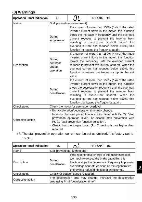
136
3
(3) Warnings
Operation Panel Indication OL FR-PU04 OL
Name Stall prevention (overcurrent)
Duringacceleration
If a current of more than 150% (* 4) of the ratedinverter current flows in the motor, this functionstops the increase in frequency until the overloadcurrent reduces to prevent the inverter fromresulting in overcurrent shut-off. When theoverload current has reduced below 150%, thisfunction increases the frequency again.
Duringconstant-speedoperation
If a current of more than 150% (* 4) of the ratedinverter current flows in the motor, this functionlowers the frequency until the overload currentreduces to prevent overcurrent shut-off. When theoverload current has reduced below 150%, thisfunction increases the frequency up to the setvalue.
Description
Duringdeceleration
If a current of more than 150% (* 4) of the ratedinverter current flows in the motor, this functionstops the decrease in frequency until the overloadcurrent reduces to prevent the inverter fromresulting in overcurrent shut-off. When theoverload current has reduced below 150%, thisfunction decreases the frequency again.
Check point Check the motor for use under overload.
Corrective action
The acceleration/deceleration time may change.Increase the stall prevention operation level with Pr. 22 "stallprevention operation level", or disable stall prevention withPr. 21 "stall prevention function selection".Check that the torque boost (Pr. 0) setting is not higher thanrequired.
*4. The stall prevention operation current can be set as desired. It is factory-set to150%.
Operation Panel Indication oL FR-PU04 oL
Name Stall prevention (overvoltage)
DescriptionDuringdeceleration
If the regenerative energy of the motor increasestoo much to exceed the brake capability, thisfunction stops the decrease in frequency to preventovervoltage shut-off. As soon as the regenerativeenergy has reduced, deceleration resumes.
Check point Check for sudden speed reduction.
Corrective actionThe deceleration time may change. Increase the decelerationtime using Pr. 8 "deceleration time".
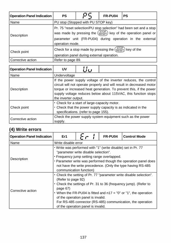
137
Operation Panel Indication PS FR-PU04 PS
Name PU stop (Stopped with PU STOP key)
Description
Pr. 75 "reset selection/PU stop selection" had been set and a stop
was made by pressing the STOPRESET key of the operation panel or
parameter unit (FR-PU04) during operation in the external
operation mode.
Check pointCheck for a stop made by pressing the STOP
RESET key of the
operation panel during external operation.Corrective action Refer to page 89.
Operation Panel Indication UV
Name Undervoltage
Description
If the power supply voltage of the inverter reduces, the controlcircuit will not operate properly and will result in decreased motortorque or increased heat generation. To prevent this, if the powersupply voltage reduces below about 115VAC, this function stopsthe inverter output.
Check pointCheck for a start of large-capacity motor.Check that the power supply capacity is as indicated in thespecifications. (refer to page 155).
Corrective actionCheck the power supply system equipment such as the powersupply.
(4) Write errors
Operation Panel Indication Er1 FR-PU04 Control Mode
Name Write disable error
Description
Write was performed with "1" (write disable) set in Pr. 77"parameter write disable selection".
Frequency jump setting range overlapped. Parameter write was performed though the operation panel doesnot have the write precedence. (Only the type having RS-485communication function)
Corrective action
Check the setting of Pr. 77 "parameter write disable selection".(Refer to page 92)Check the settings of Pr. 31 to 36 (frequency jump). (Refer topage 67)When the FR-PU04 is fitted and n17 = "0" or "1", the operationof the operation panel is invalid.For RS-485 connector (RS-485) communication, the operationof the operation panel is invalid.
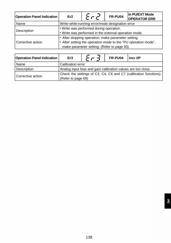
138
3
Operation Panel Indication Er2 FR-PU04In PU/EXT ModeOPERATOR ERR
Name Write-while-running error/mode designation error
Description Write was performed during operation. Write was performed in the external operation mode.
Corrective actionAfter stopping operation, make parameter setting.After setting the operation mode to the "PU operation mode",make parameter setting. (Refer to page 93)
Operation Panel Indication Er3 FR-PU04 Incr I/P
Name Calibration errorDescription Analog input bias and gain calibration values are too close.
Corrective actionCheck the settings of C3, C4, C6 and C7 (calibration functions).(Refer to page 69)
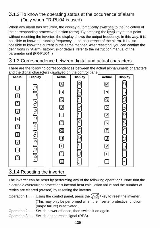
139
3.1.2 To know the operating status at the occurrence of alarm(Only when FR-PU04 is used)
When any alarm has occurred, the display automatically switches to the indication ofthe corresponding protective function (error). By pressing the MON key at this pointwithout resetting the inverter, the display shows the output frequency. In this way, it ispossible to know the running frequency at the occurrence of the alarm. It is alsopossible to know the current in the same manner. After resetting, you can confirm thedefinitions in "Alarm History". (For details, refer to the instruction manual of theparameter unit (FR-PU04).)
3.1.3 Correspondence between digital and actual characters
There are the following correspondences between the actual alphanumeric charactersand the digital characters displayed on the control panel:
Actual Display Actual Display Actual Display
0
1
2
3
4
5
6
7
8
9
A
B
C
D
E
F
G
H
I
J
L
M
N
O
P
T
U
V
r
-
S
o
3.1.4 Resetting the inverter
The inverter can be reset by performing any of the following operations. Note that theelectronic overcurrent protection's internal heat calculation value and the number ofretries are cleared (erased) by resetting the inverter.
Operation 1: ......Using the control panel, press the STOPRESET key to reset the inverter.
(This may only be performed when the inverter protective function(major failure) is activated.)
Operation 2: ......Switch power off once, then switch it on again.Operation 3: ......Switch on the reset signal (RES).
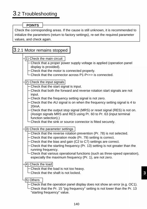
140
3
3.2 Troubleshooting
POINTS
Check the corresponding areas. If the cause is still unknown, it is recommended toinitialize the parameters (return to factory settings), re-set the required parametervalues, and check again.
3.2.1 Motor remains stopped
1) Check the main circuitCheck that a proper power supply voltage is applied (operation paneldisplay is provided).Check that the motor is connected properly.Check that the connector across P1-P<+> is connected.
2) Check the input signalsCheck that the start signal is input.Check that both the forward and reverse rotation start signals are notinput.Check that the frequency setting signal is not zero.Check that the AU signal is on when the frequency setting signal is 4 to20mA.Check that the output stop signal (MRS) or reset signal (RES) is not on.(Assign signals MRS and RES using Pr. 60 to Pr. 63 (input terminalfunction selection).)Check that the sink or source connector is fitted securely.
3) Check the parameter settingsCheck that the reverse rotation prevention (Pr. 78) is not selected.Check that the operation mode (Pr. 79) setting is correct.Check that the bias and gain (C2 to C7) settings are correct.Check that the starting frequency (Pr. 13) setting is not greater than therunning frequency.Check that various operational functions (such as three-speed operation),especially the maximum frequency (Pr. 1), are not zero.
4) Check the loadCheck that the load is not too heavy.Check that the shaft is not locked.
5) OthersCheck that the operation panel display does not show an error (e.g. OC1).Check that the Pr. 15 "jog frequency" setting is not lower than the Pr. 13"starting frequency" value.
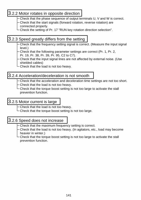
141
3.2.2 Motor rotates in opposite directionCheck that the phase sequence of output terminals U, V and W is correct.Check that the start signals (forward rotation, reverse rotation) areconnected properly.Check the setting of Pr. 17 "RUN key rotation direction selection".
3.2.3 Speed greatly differs from the settingCheck that the frequency setting signal is correct. (Measure the input signallevel.)Check that the following parameter settings are correct (Pr. 1, Pr. 2,Pr. 19, Pr. 38, Pr. 39, Pr. 95, C2 to C7).Check that the input signal lines are not affected by external noise. (Useshielded cables)Check that the load is not too heavy.
3.2.4 Acceleration/deceleration is not smoothCheck that the acceleration and deceleration time settings are not too short.Check that the load is not too heavy.Check that the torque boost setting is not too large to activate the stallprevention function.
3.2.5 Motor current is largeCheck that the load is not too heavy.Check that the torque boost setting is not too large.
3.2.6 Speed does not increaseCheck that the maximum frequency setting is correct.Check that the load is not too heavy. (In agitators, etc., load may becomeheavier in winter.)Check that the torque boost setting is not too large to activate the stallprevention function.
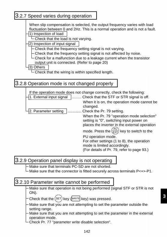
142
3
3.2.7 Speed varies during operation
When slip compensation is selected, the output frequency varies with loadfluctuation between 0 and 2Hz. This is a normal operation and is not a fault.1) Inspection of load
Check that the load is not varying.2) Inspection of input signal
Check that the frequency setting signal is not varying.Check that the frequency setting signal is not affected by noise.Check for a malfunction due to a leakage current when the transistoroutput unit is connected. (Refer to page 20)
3) OthersCheck that the wiring is within specified length.
3.2.8 Operation mode is not changed properly
If the operation mode does not change correctly, check the following:1. External input signal ......... Check that the STF or STR signal is off.
When it is on, the operation mode cannot bechanged.
2. Parameter setting ............. Check the Pr. 79 setting.When the Pr. 79 "operation mode selection"setting is "0", switching input power onplaces the inverter in the external operation
mode. Press the PUEXT key to switch to the
PU operation mode.For other settings (1 to 8), the operationmode is limited accordingly.(For details of Pr. 79, refer to page 93.)
3.2.9 Operation panel display is not operatingMake sure that terminals PC-SD are not shorted.Make sure that the connector is fitted securely across terminals P<+>-P1.
3.2.10 Parameter write cannot be performedMake sure that operation is not being performed (signal STF or STR is notON).
Check that the SET key ( WRITE key) was pressed.
Make sure that you are not attempting to set the parameter outside thesetting range.Make sure that you are not attempting to set the parameter in the externaloperation mode.Check Pr. 77 "parameter write disable selection".
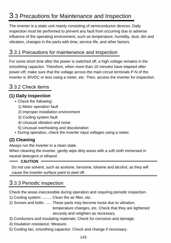
143
3.3 Precautions for Maintenance and Inspection
The inverter is a static unit mainly consisting of semiconductor devices. Dailyinspection must be performed to prevent any fault from occurring due to adverseinfluence of the operating environment, such as temperature, humidity, dust, dirt andvibration, changes in the parts with time, service life, and other factors.
3.3.1 Precautions for maintenance and inspection
For some short time after the power is switched off, a high voltage remains in thesmoothing capacitor. Therefore, when more than 10 minutes have elapsed afterpower-off, make sure that the voltage across the main circuit terminals P-N of theinverter is 30VDC or less using a meter, etc. Then, access the inverter for inspection.
3.3.2 Check items
(1) Daily inspection• Check the following:
1) Motor operation fault2) Improper installation environment3) Cooling system fault4) Unusual vibration and noise5) Unusual overheating and discoloration
• During operation, check the inverter input voltages using a meter.
(2) CleaningAlways run the inverter in a clean state.When cleaning the inverter, gently wipe dirty areas with a soft cloth immersed inneutral detergent or ethanol.
CAUTION
Do not use solvent, such as acetone, benzene, toluene and alcohol, as they willcause the inverter surface paint to peel off.
3.3.3 Periodic inspection
Check the areas inaccessible during operation and requiring periodic inspection.1) Cooling system: ......... Clean the air filter, etc.2) Screws and bolts: ...... These parts may become loose due to vibration,
temperature changes, etc. Check that they are tightenedsecurely and retighten as necessary.
3) Conductors and insulating materials: Check for corrosion and damage.4) Insulation resistance: Measure.5) Cooling fan, smoothing capacitor: Check and change if necessary.
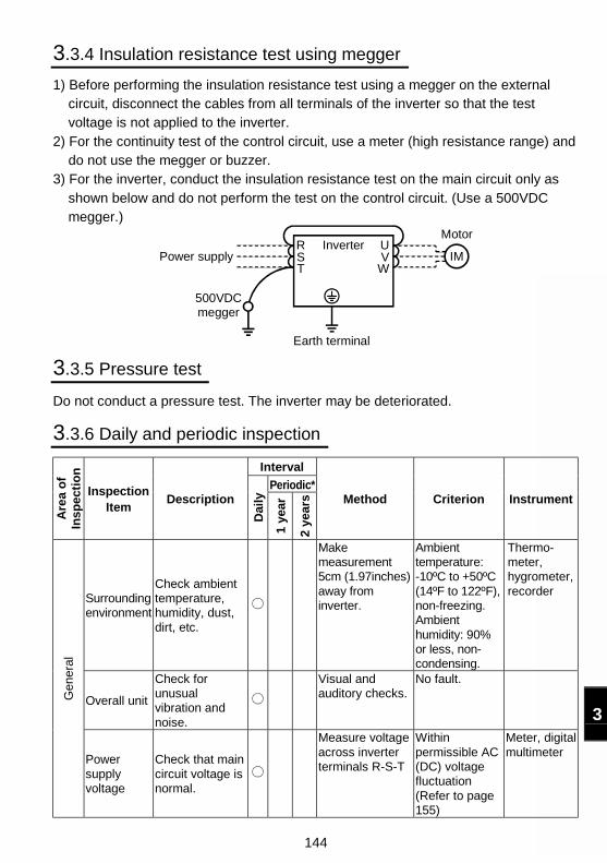
144
3
3.3.4 Insulation resistance test using megger
1) Before performing the insulation resistance test using a megger on the externalcircuit, disconnect the cables from all terminals of the inverter so that the testvoltage is not applied to the inverter.
2) For the continuity test of the control circuit, use a meter (high resistance range) anddo not use the megger or buzzer.
3) For the inverter, conduct the insulation resistance test on the main circuit only asshown below and do not perform the test on the control circuit. (Use a 500VDCmegger.)
RST
UV
W
Inverter
Earth terminal
500VDC megger
Power supply IM
Motor
3.3.5 Pressure test
Do not conduct a pressure test. The inverter may be deteriorated.
3.3.6 Daily and periodic inspection
Interval
Periodic*
Are
a o
fIn
spec
tio
n
InspectionItem
Description
Dai
ly
1 ye
ar
2 ye
ars Method Criterion Instrument
Surroundingenvironment
Check ambienttemperature,humidity, dust,dirt, etc.
Makemeasurement5cm (1.97inches)away frominverter.
Ambienttemperature:-10ºC to +50ºC(14ºF to 122ºF),non-freezing.Ambienthumidity: 90%or less, non-condensing.
Thermo-meter,hygrometer,recorder
Overall unit
Check forunusualvibration andnoise.
Visual andauditory checks.
No fault.
Gen
eral
Powersupplyvoltage
Check that maincircuit voltage isnormal.
Measure voltageacross inverterterminals R-S-T
Withinpermissible AC(DC) voltagefluctuation(Refer to page155)
Meter, digitalmultimeter

145
Interval
Periodic*
Are
a o
fIn
spec
tio
n
InspectionItem
Description
Dai
ly
1 ye
ar
2 ye
ars Method Criterion Instrument
Gen
eral
General
(1) Check withmegger(acrossmain circuitterminalsand groundterminal).
(2) Check forloose screwsand bolts.
(3) Check foroverheat oneach part.
(4) Clean.
(1) Disconnectall cablesfrom inverterand measureacrossterminals R,S, T, U, V, Wand groundterminal withmegger.
(2) Retighten.(3) Visual check.
(1) 5MΩ ormore.
(2), (3) Nofault.
500VDCclassmegger
Conductors,cables
(1) Checkconductorsfor distortion.
(2) Check cablesheaths forbreakage.
(1), (2) Visualcheck.
(1), (2) No fault.
Terminalblock
Check fordamage. Visual check No fault
InvertermoduleConvertermodule
Checkresistanceacrossterminals.
Disconnectcables frominverter andmeasureacrossterminals R, S,T↔P, N, andacross U, V,W↔P, N witha meter with a100Ω range.
Refer to page147.
Analogmeter
Mai
n ci
rcui
t
Smoothingcapacitor
(1) Check forliquidleakage.
(2) Check forsafety valveprojectionand bulge.
(3) Measureelectrostaticcapacity.
(1), (2) Visualcheck.
(3) Measure withcapacitymeter.
(1), (2) No fault.(3) 85% or
more ofratedcapacity.
Capacitymeter
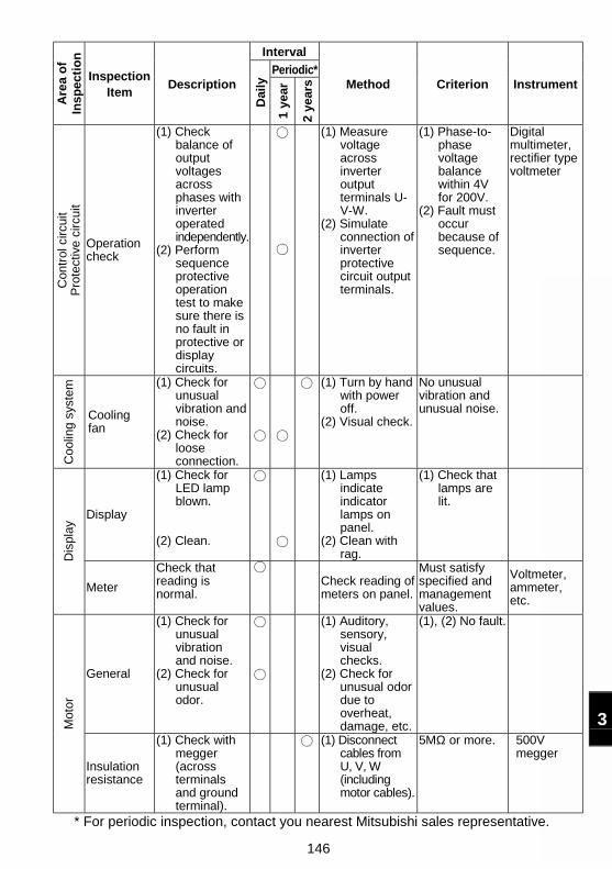
146
3
Interval
Periodic*A
rea
of
Insp
ecti
on
InspectionItem
Description
Dai
ly
1 ye
ar
2 ye
ars Method Criterion Instrument
Con
trol
circ
uit
Pro
tect
ive
circ
uit
Operationcheck
(1) Checkbalance ofoutputvoltagesacrossphases withinverteroperatedindependently.
(2) Performsequenceprotectiveoperationtest to makesure there isno fault inprotective ordisplaycircuits.
(1) Measurevoltageacrossinverteroutputterminals U-V-W.
(2) Simulateconnection ofinverterprotectivecircuit outputterminals.
(1) Phase-to-phasevoltagebalancewithin 4Vfor 200V.
(2) Fault mustoccurbecause ofsequence.
Digitalmultimeter,rectifier typevoltmeter
Coo
ling
syst
em
Coolingfan
(1) Check forunusualvibration andnoise.
(2) Check forlooseconnection.
(1) Turn by handwith poweroff.
(2) Visual check.
No unusualvibration andunusual noise.
Display
(1) Check forLED lampblown.
(2) Clean.
(1) Lampsindicateindicatorlamps onpanel.
(2) Clean withrag.
(1) Check thatlamps arelit.
Dis
play
Meter
Check thatreading isnormal.
Check reading ofmeters on panel.
Must satisfyspecified andmanagementvalues.
Voltmeter,ammeter,etc.
General
(1) Check forunusualvibrationand noise.
(2) Check forunusualodor.
(1) Auditory,sensory,visualchecks.
(2) Check forunusual odordue tooverheat,damage, etc.
(1), (2) No fault.
Mot
or
Insulationresistance
(1) Check withmegger(acrossterminalsand groundterminal).
(1) Disconnectcables fromU, V, W(includingmotor cables).
5MΩ or more. 500Vmegger
* For periodic inspection, contact you nearest Mitsubishi sales representative.
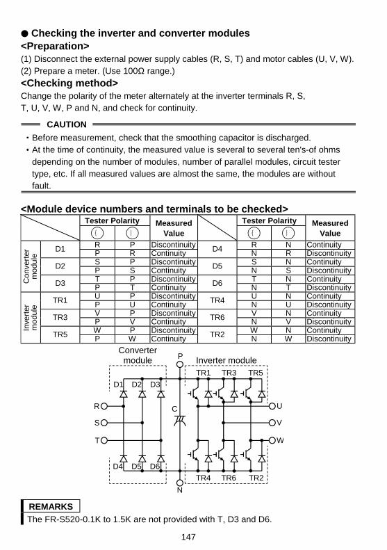
147
Checking the inverter and converter modules<Preparation>(1) Disconnect the external power supply cables (R, S, T) and motor cables (U, V, W).(2) Prepare a meter. (Use 100Ω range.)
<Checking method>Change the polarity of the meter alternately at the inverter terminals R, S,T, U, V, W, P and N, and check for continuity.
CAUTION
Before measurement, check that the smoothing capacitor is discharged.At the time of continuity, the measured value is several to several ten's-of ohmsdepending on the number of modules, number of parallel modules, circuit testertype, etc. If all measured values are almost the same, the modules are withoutfault.
<Module device numbers and terminals to be checked>Tester Polarity Tester Polarity
|Measured
Value |Measured
Value
R P Discontinuity R N ContinuityD1 P R Continuity D4 N R DiscontinuityS P Discontinuity S N ContinuityD2 P S Continuity D5 N S DiscontinuityT P Discontinuity T N ContinuityC
onve
rter
mod
ule
D3 P T Continuity D6 N T DiscontinuityU P Discontinuity U N ContinuityTR1 P U Continuity TR4 N U DiscontinuityV P Discontinuity V N ContinuityTR3 P V Continuity TR6 N V DiscontinuityW P Discontinuity W N ContinuityIn
vert
erm
odul
e
TR5 P W Continuity TR2 N W Discontinuity
Convertermodule Inverter module
D1 D2 D3
D4 D5 D6
TR1 TR3 TR5
TR4 TR6 TR2
U
V
W
R
S
T
C
P
N
REMARKS
The FR-S520-0.1K to 1.5K are not provided with T, D3 and D6.
148
3
3.3.7 Replacement of parts
The inverter consists of many electronic parts such as semiconductor devices.The following parts may deteriorate with age because of their structural or physicalcharacteristics, leading to reduced performance or failure of the inverter. Forpreventive maintenance, the parts must be changed periodically.
Part NameStandard Replacement
IntervalDescription
Cooling fan 2 to 3 years Change (as required)
Smoothing capacitor in main circuit 5 years Change (as required)
Smoothing capacitor on control board 5 years Change the board (as required).
CAUTION
For parts replacement, consult the nearest Mitsubishi FA Center.
(1) Cooling fan (FR-S520-1.5K to 3.7K, FR-S520S-1.5K)The cooling fan used to cool heat-generating parts such as the main circuitsemiconductors has a bearing whose life is said to be 10,000 to 35,000 hours. Hence,the cooling fan must be changed every 2 to 3 years if the inverter is run continuously.When unusual noise and/or vibration is noticed during inspection, the cooling fan mustbe changed immediately.
Fan Type
MMF-06D24DS BKO-C2416H07
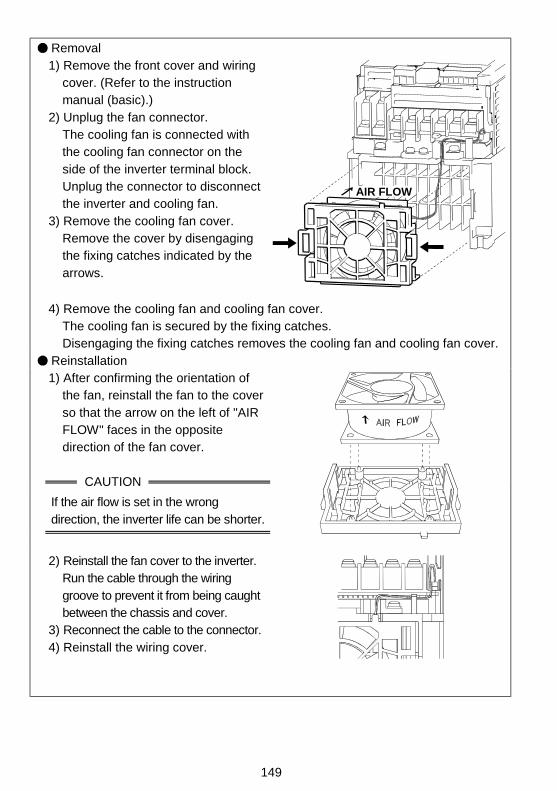
149
Removal1) Remove the front cover and wiring
cover. (Refer to the instructionmanual (basic).)
2) Unplug the fan connector.The cooling fan is connected withthe cooling fan connector on theside of the inverter terminal block.Unplug the connector to disconnectthe inverter and cooling fan.
3) Remove the cooling fan cover.Remove the cover by disengagingthe fixing catches indicated by thearrows.
AIR FLOW
4) Remove the cooling fan and cooling fan cover.The cooling fan is secured by the fixing catches.Disengaging the fixing catches removes the cooling fan and cooling fan cover.
Reinstallation1) After confirming the orientation of
the fan, reinstall the fan to the coverso that the arrow on the left of "AIRFLOW" faces in the oppositedirection of the fan cover.
CAUTION
If the air flow is set in the wrongdirection, the inverter life can be shorter.
2) Reinstall the fan cover to the inverter.Run the cable through the wiringgroove to prevent it from being caughtbetween the chassis and cover.
3) Reconnect the cable to the connector.4) Reinstall the wiring cover.
150
3
(2) Smoothing capacitorsA large-capacity aluminum electrolytic capacitor is used for smoothing the DC in themain circuit, and an aluminum electrolytic capacitor is also used for stabilizing thecontrol power in the control circuit.Their characteristics are adversely affected by ripple current, etc. When the inverter isoperated in an ordinary, air-conditioned environment, change the capacitors aboutevery 5 years. When 5 years have elapsed, the capacitors will deteriorate morerapidly. Check the capacitors at least every year (less than six months if the life will beexpired soon). Check the following:1) Case (side faces and bottom face for expansion)2) Sealing plate (for remarkable warp and extreme crack)3) Appearance, external cracks, discoloration, leakage.
When the measured capacitance of the capacitor has reduced below 85% of therating, change the capacitor.For measurement of the capacity of the capacitor, it is recommended to use simpleequipment recently available on the market.
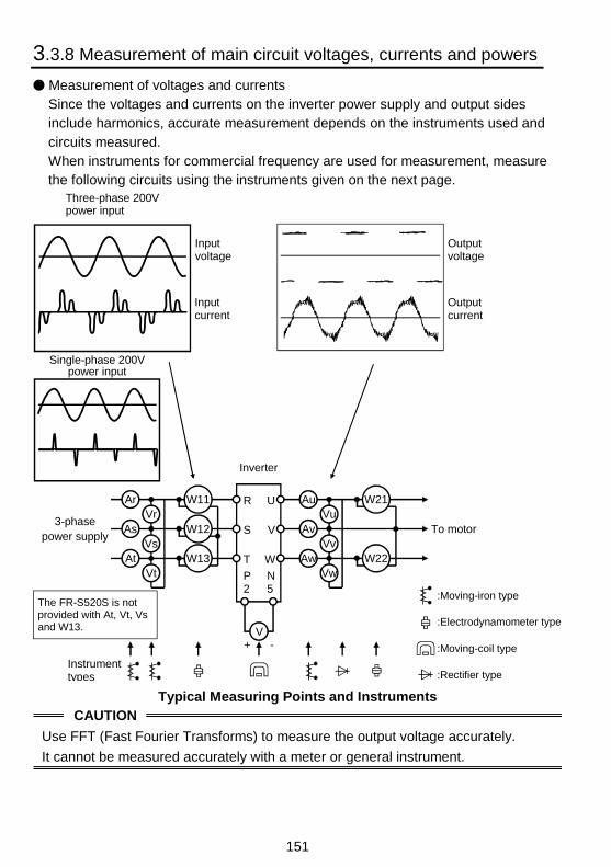
151
3.3.8 Measurement of main circuit voltages, currents and powers
Measurement of voltages and currentsSince the voltages and currents on the inverter power supply and output sidesinclude harmonics, accurate measurement depends on the instruments used andcircuits measured.When instruments for commercial frequency are used for measurement, measurethe following circuits using the instruments given on the next page.
:Moving-iron type
:Electrodynamometer type
:Moving-coil type
:Rectifier type
+ -
Ar
As
At
Vr
Vs
Vt
W11
W12
W13
Au
Av
Aw
Vu
Vv
Vw
W21
W22
V
R
S
T
P2
U
V
W
N5
Instrument types
Three-phase 200Vpower input
Inputvoltage
Inputcurrent
Outputvoltage
Outputcurrent
Inverter
3-phasepower supply
To motor
Single-phase 200Vpower input
The FR-S520S is not provided with At, Vt, Vs and W13.
Typical Measuring Points and InstrumentsCAUTION
Use FFT (Fast Fourier Transforms) to measure the output voltage accurately.
It cannot be measured accurately with a meter or general instrument.
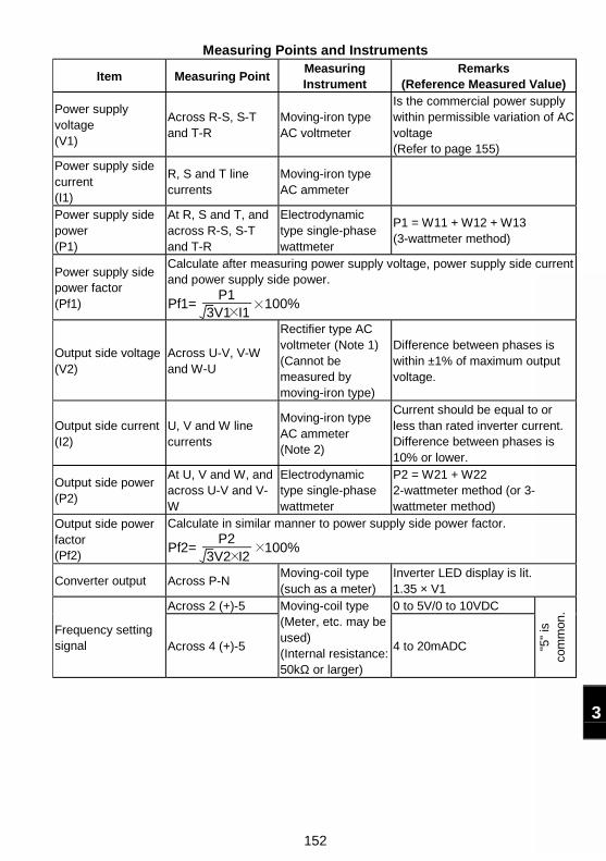
152
3
Measuring Points and Instruments
Item Measuring PointMeasuringInstrument
Remarks(Reference Measured Value)
Power supplyvoltage(V1)
Across R-S, S-Tand T-R
Moving-iron typeAC voltmeter
Is the commercial power supplywithin permissible variation of ACvoltage(Refer to page 155)
Power supply sidecurrent(I1)
R, S and T linecurrents
Moving-iron typeAC ammeter
Power supply sidepower(P1)
At R, S and T, andacross R-S, S-Tand T-R
Electrodynamictype single-phasewattmeter
P1 = W11 + W12 + W13(3-wattmeter method)
Power supply sidepower factor(Pf1)
Calculate after measuring power supply voltage, power supply side currentand power supply side power.
Pf1=P1
3V1 I1 100%
Output side voltage(V2)
Across U-V, V-Wand W-U
Rectifier type ACvoltmeter (Note 1)(Cannot bemeasured bymoving-iron type)
Difference between phases iswithin ±1% of maximum outputvoltage.
Output side current(I2)
U, V and W linecurrents
Moving-iron typeAC ammeter(Note 2)
Current should be equal to orless than rated inverter current.Difference between phases is10% or lower.
Output side power(P2)
At U, V and W, andacross U-V and V-W
Electrodynamictype single-phasewattmeter
P2 = W21 + W222-wattmeter method (or 3-wattmeter method)
Output side powerfactor(Pf2)
Calculate in similar manner to power supply side power factor.
Pf2=P2
3V2 I2 100%
Converter output Across P-NMoving-coil type(such as a meter)
Inverter LED display is lit.1.35 × V1
Across 2 (+)-5 0 to 5V/0 to 10VDC
Frequency settingsignal Across 4 (+)-5
Moving-coil type(Meter, etc. may beused)(Internal resistance:50kΩ or larger)
4 to 20mADC "5"
isco
mm
on.
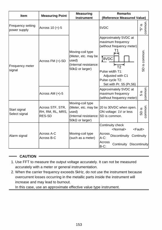
153
Item Measuring PointMeasuringInstrument
Remarks(Reference Measured Value)
Frequency settingpower supply
Across 10 (+)-5 5VDC
"5"
isco
mm
on.
Across FM (+)-SD
Approximately 5VDC atmaximum frequency(without frequency meter)
8VDC
T1
T2Pulse width T1:
Adjusted with C1Pulse cycle T2:
Set with Pr. 55 (Pr,56)
SD
is c
omm
on.
Frequency metersignal
Across AM (+)-5
Moving-coil type(Meter, etc. may beused)(Internal resistance:50kΩ or larger)
Approximately 5VDC atmaximum frequency(without frequency meter)
5 is
com
mon
.
Start signalSelect signal
Across STF, STR,RH, RM, RL, MRS,RES-SD
Moving-coil type(Meter, etc. may beused)(Internal resistance:50kΩ or larger)
20 to 30VDC when open.ON voltage: 1V or lessSD is common. S
D is
com
mon
.
Continuity check<Normal> <Fault>
AcrossA-C:
Discontinuity ContinuityAlarm signalAcross A-CAcross B-C
Moving-coil type(such as a meter)
AcrossB-C:
Continuity Discontinuity
CAUTION
1. Use FFT to measure the output voltage accurately. It can not be measuredaccurately with a meter or general instrumentation.
2. When the carrier frequency exceeds 5kHz, do not use the instrument becauseovercurrent losses occurring in the metallic parts inside the instrument willincrease and may lead to burnout.In this case, use an approximate effective value type instrument.
154
4
This chapter provides the "specifications" of this product.Always read the instructions before using the equipment
4.1 Specification List...................................................1554.2 Outline drawings ...................................................159
4. SPECIFI-CATIONS
Chapter 1
Chapter 2
Chapter 3
Chapter 4
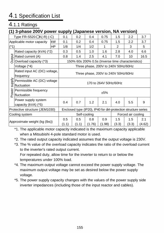
155
4.1 Specification List
4.1.1 Ratings
(1) 3-phase 200V power supply (Japanese version, NA version)Type FR-S520- K(-R) (-C) 0.1 0.2 0.4 0.75 1.5 2.2 3.7
kW 0.1 0.2 0.4 0.75 1.5 2.2 3.7Applicable motor capacity
(*1) HP 1/8 1/4 1/2 1 2 3 5
Rated capacity (kVA) (*2) 0.3 0.5 1.0 1.6 2.8 4.0 6.6
Rated current (A) 0.8 1.4 2.5 4.1 7.0 10 16.5
Overload capacity (*3) 150% 60s 200% 0.5s (Inverse time characteristics)Out
put
Voltage (*4) Three phase, 200V to 240V 50Hz/60Hz
Rated input AC (DC) voltage,
frequencyThree phase, 200V to 240V 50Hz/60Hz
Permissible AC (DC) voltage
fluctuation170 to 264V 50Hz/60Hz
Permissible frequency
fluctuation±5%
Pow
er s
uppl
y
Power supply system
capacity (kVA) (*5)0.4 0.7 1.2 2.1 4.0 5.5 9
Protective structure (JEM1030) Enclosed type (IP20), IP40 for dirt-protection structure series
Cooling system Self-cooling Forced air cooling
Approximate weight (kg (lbs))0.5
(1.1)
0.5
(1.1)
0.8
(1.76)
0.9
(1.98)
1.5
(3.3)
1.5
(3.3)
2.1
(4.62)
*1. The applicable motor capacity indicated is the maximum capacity applicablewhen a Mitsubishi 4-pole standard motor is used.
*2. The rated output capacity indicated assumes that the output voltage is 230V.*3. The % value of the overload capacity indicates the ratio of the overload current
to the inverter's rated output current.For repeated duty, allow time for the inverter to return to or below thetemperatures under 100% load.
*4. The maximum output voltage cannot exceed the power supply voltage. Themaximum output voltage may be set as desired below the power supplyvoltage.
*5. The power supply capacity changes with the values of the power supply sideinverter impedances (including those of the input reactor and cables).
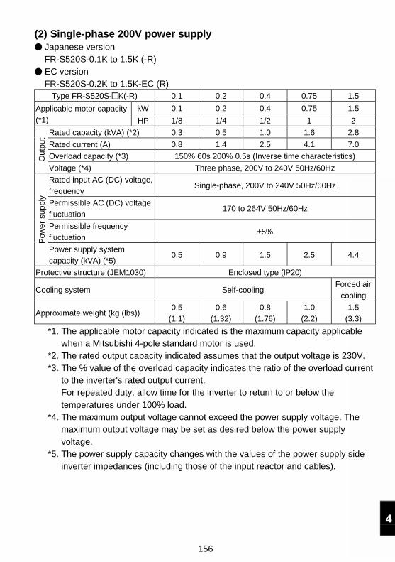
156
4
(2) Single-phase 200V power supply Japanese versionFR-S520S-0.1K to 1.5K (-R) EC versionFR-S520S-0.2K to 1.5K-EC (R)
Type FR-S520S- K(-R) 0.1 0.2 0.4 0.75 1.5
kW 0.1 0.2 0.4 0.75 1.5Applicable motor capacity
(*1) HP 1/8 1/4 1/2 1 2
Rated capacity (kVA) (*2) 0.3 0.5 1.0 1.6 2.8
Rated current (A) 0.8 1.4 2.5 4.1 7.0
Overload capacity (*3) 150% 60s 200% 0.5s (Inverse time characteristics)Out
put
Voltage (*4) Three phase, 200V to 240V 50Hz/60Hz
Rated input AC (DC) voltage,
frequencySingle-phase, 200V to 240V 50Hz/60Hz
Permissible AC (DC) voltage
fluctuation170 to 264V 50Hz/60Hz
Permissible frequency
fluctuation±5%
Pow
er s
uppl
y
Power supply system
capacity (kVA) (*5)0.5 0.9 1.5 2.5 4.4
Protective structure (JEM1030) Enclosed type (IP20)
Cooling system Self-coolingForced air
cooling
Approximate weight (kg (lbs))0.5
(1.1)
0.6
(1.32)
0.8
(1.76)
1.0
(2.2)
1.5
(3.3)
*1. The applicable motor capacity indicated is the maximum capacity applicablewhen a Mitsubishi 4-pole standard motor is used.
*2. The rated output capacity indicated assumes that the output voltage is 230V.*3. The % value of the overload capacity indicates the ratio of the overload current
to the inverter's rated output current.For repeated duty, allow time for the inverter to return to or below thetemperatures under 100% load.
*4. The maximum output voltage cannot exceed the power supply voltage. Themaximum output voltage may be set as desired below the power supplyvoltage.
*5. The power supply capacity changes with the values of the power supply sideinverter impedances (including those of the input reactor and cables).
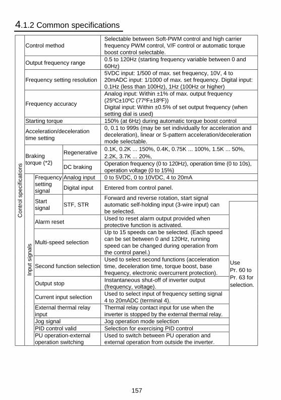
157
4.1.2 Common specifications
Control methodSelectable between Soft-PWM control and high carrierfrequency PWM control, V/F control or automatic torqueboost control selectable.
Output frequency range0.5 to 120Hz (starting frequency variable between 0 and60Hz)
Frequency setting resolution5VDC input: 1/500 of max. set frequency, 10V, 4 to20mADC input: 1/1000 of max. set frequency. Digital input:0.1Hz (less than 100Hz), 1Hz (100Hz or higher)
Frequency accuracy
Analog input: Within ±1% of max. output frequency(25ºC±10ºC (77ºF±18ºF))Digital input: Within ±0.5% of set output frequency (whensetting dial is used)
Starting torque 150% (at 6Hz) during automatic torque boost control
Acceleration/decelerationtime setting
0, 0.1 to 999s (may be set individually for acceleration anddeceleration), linear or S-pattern acceleration/decelerationmode selectable.
Regenerative0.1K, 0.2K ... 150%, 0.4K, 0.75K ... 100%, 1.5K ... 50%,2.2K, 3.7K ... 20%,Braking
torque (*2)DC braking
Operation frequency (0 to 120Hz), operation time (0 to 10s),operation voltage (0 to 15%)
Analog input 0 to 5VDC, 0 to 10VDC, 4 to 20mAFrequencysettingsignal Digital input Entered from control panel.
Startsignal
STF, STRForward and reverse rotation, start signalautomatic self-holding input (3-wire input) canbe selected.
Alarm resetUsed to reset alarm output provided whenprotective function is activated.
Multi-speed selection
Up to 15 speeds can be selected. (Each speedcan be set between 0 and 120Hz, runningspeed can be changed during operation fromthe control panel.)
Second function selectionUsed to select second functions (accelerationtime, deceleration time, torque boost, basefrequency, electronic overcurrent protection).
Output stopInstantaneous shut-off of inverter output(frequency, voltage).
Current input selectionUsed to select input of frequency setting signal4 to 20mADC (terminal 4).
External thermal relayinput
Thermal relay contact input for use when theinverter is stopped by the external thermal relay.
Jog signal Jog operation mode selectionPID control valid Selection for exercising PID control
Con
trol
spe
cific
atio
ns
Inpu
t si
gnal
s
PU operation-externaloperation switching
Used to switch between PU operation andexternal operation from outside the inverter.
UsePr. 60 toPr. 63 forselection.
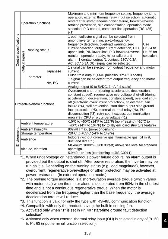
158
4
Operation functions
Maximum and minimum frequency setting, frequency jumpoperation, external thermal relay input selection, automaticrestart after instantaneous power failure, forward/reverserotation prevention, slip compensation, operation modeselection, PID control, computer link operation (RS-485)(*3)
Running status
1 open collector signal can be selected fromamong inverter running, up-to-frequency,frequency detection, overload warning, zerocurrent detection, output current detection, PIDupper limit, PID lower limit, PID forward/reverserotation, operation ready, minor failure andalarm. 1 contact output (1 contact, 230V 0.3AAC, 30V 0.3A DC) signal can be selected.
UsePr. 64 toPr. 65 forselection.
Japanese1 signal can be selected from output frequency and motorcurrent.Pulse train output (1440 pulses/s, 1mA full scale)
Con
trol
spe
cific
atio
ns
Out
put
sign
als
For meter
NA, EC1 signal can be selected from output frequency and motorcurrent.Analog output (0 to 5VDC, 1mA full scale)
Protective/alarm functions
Overcurrent shut-off (during acceleration, deceleration,constant speed), regenerative overvoltage shut-off (duringacceleration, deceleration, constant speed), overload shut-off (electronic overcurrent protection), fin overheat, fanfailure (*4), stall prevention, start-time output side groundfault protection (*5), external thermal relay (*6), PUdisconnection (*3), retry count excess, communicationerror (*3), CPU error, undervoltage (*1)
Ambient temperature-10ºC to +50ºC (14°F to 122°F) (non-freezing) (-10°C to+40°C (14°F to 104°F) for totally enclosed structure feature)
Ambient humidity 90%RH max. (non-condensing)Storage temperature -20ºC to +65ºC (-4°F to 149°F)
AmbienceIndoors (without corrosive gas, flammable gas, oil mist,dust and dirt etc.)
Env
iron
men
t
Altitude, vibrationMaximum 1000m (3280.80feet) above sea level for standardoperation.5.9m/s2 or less (conforming to JIS C0911)
*1. When undervoltage or instantaneous power failure occurs, no alarm output isprovided but the output is shut off. After power restoration, the inverter may berun as it is. Depending on the running status (e.g. load magnitude), however,overcurrent, regenerative overvoltage or other protection may be activated atpower restoration. (In external operation mode.)
*2. The braking torque indicated is a short-duration average torque (which varieswith motor loss) when the motor alone is decelerated from 60Hz in the shortesttime and is not a continuous regenerative torque. When the motor isdecelerated from the frequency higher than the base frequency, the averagedeceleration torque will reduce.
*3. This function is valid for only the type with RS-485 communication function.*4. Compatible with only the product having the built-in cooling fan.*5. Activated only when "1" is set in Pr. 40 "start-time ground fault detection
selection".*6. Activated only when external thermal relay input (OH) is selected in any of Pr. 60
to Pr. 63 (input terminal function selection).
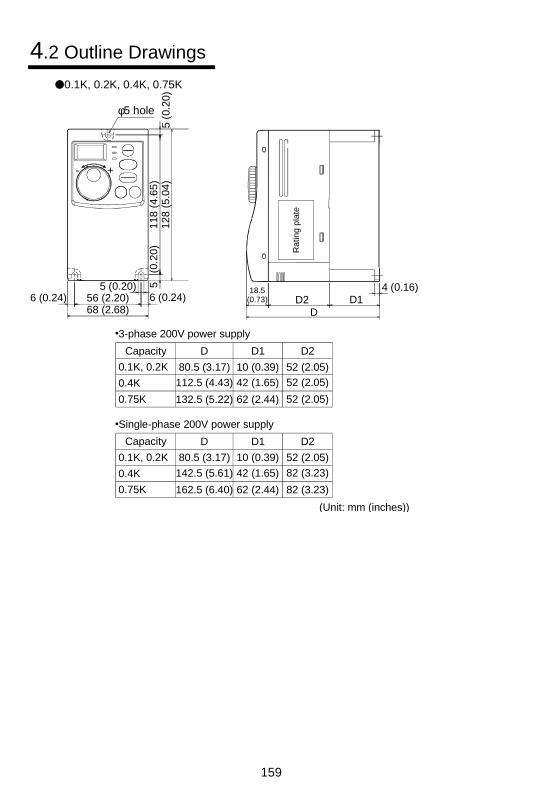
159
4.2 Outline Drawings
0.1K, 0.2K, 0.4K, 0.75K
φ5 hole
68 (2.68)6 (0.24) 56 (2.20) 6 (0.24)
5 (0.20)
128
(5.0
4)5
(0
.20)
118
(4.6
5)
- +5
(0.2
0)
18.5(0.73) D1
4 (0.16)D2
D
Capacity
0.1K, 0.2K
0.4K
0.75K 132.5 (5.22)
112.5 (4.43)
80.5 (3.17)
D
62 (2.44)
42 (1.65)
10 (0.39)
D1
52 (2.05)
52 (2.05)
52 (2.05)
D2
Capacity
0.1K, 0.2K
0.4K
0.75K 162.5 (6.40)
142.5 (5.61)
80.5 (3.17)
D
62 (2.44)
42 (1.65)
10 (0.39)
D1
82 (3.23)
82 (3.23)
52 (2.05)
D2
(Unit: mm (inches))
Ratin
g p
late
3-phase 200V power supply
Single-phase 200V power supply
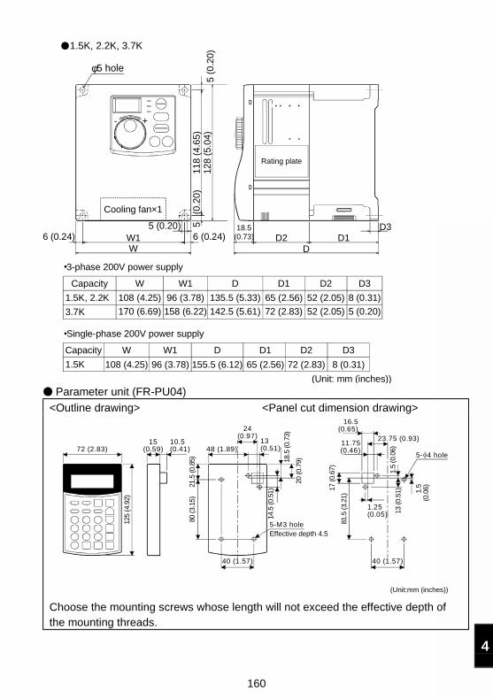
160
4
Capacity
1.5K, 2.2K
3.7K 170 (6.69)
108 (4.25)
W
158 (6.22)
96 (3.78)
W1
142.5 (5.61)
135.5 (5.33)
D
72 (2.83)
65 (2.56)
D1
52 (2.05)
52 (2.05)
D2
5 (0.20)
8 (0.31)
D3
18.5(0.73)
DD2 D1
D35 (
0.20
)11
8 (4
.65)
5 (0.20)
WW1
128
(5.0
4)5
(0.2
0)
- +
6 (0.24) 6 (0.24)
Cooling fan×1
φ5 hole
1.5K, 2.2K, 3.7K
Capacity
1.5K 108 (4.25)
W
96 (3.78)
W1
155.5 (6.12)
D
65 (2.56)
D1
72 (2.83)
D2
8 (0.31)
D3
(Unit: mm (inches))
Rating plate
3-phase 200V power supply
Single-phase 200V power supply
Parameter unit (FR-PU04)
<Outline drawing> <Panel cut dimension drawing>
40 (1.57)
23.75 (0.93)11.75(0.46)
81.5
(3.
21)
1.25(0.05)
1.5
(0.0
6)
17 (
0.67
)
16.5(0.65)
1.5
(0.0
6)
125
(4.9
2)
72 (2.83)15
(0.59)10.5(0.41)
18.5
(0.
73)
40 (1.57)
80 (
3.15
)
48 (1.89)
5-M3 hole
24(0.97)
13(0.51)
20 (
0.79
)
21.5
(0.
85)
14.5
(0.
51)
5- 4 hole
Effective depth 4.5
13 (
0.51
)
(Unit:mm (inches))
Choose the mounting screws whose length will not exceed the effective depth ofthe mounting threads.
161
5.1 Selecting Instructions............................................1625.2 Peripheral Selecting Instructions...........................1625.3 Operating Instructions...........................................164
5.INSTRUCTIONS
162
5.1 Selecting Instructions
(1) Inverter capacity selectionWhen a special motor is run or multiple motors are run in parallel by one inverter,choose the inverter capacity so that the sum of the rated motor currents (at 50Hz)will be not more than the rated output current of the inverter.
(2) Motor starting torqueThe starting and acceleration characteristics of an inverter-driven motor arerestricted by the overload capacity of the inverter used. The torque characteristicis generally smaller than at a start made by the commercial power supply. Whenlarge starting torque is necessary, choose automatic torque boost control (set themotor capacity in Pr. 98) or adjust the torque boost value. If these selection andadjustment cannot develop enough torque, choose a one rank higher invertercapacity or increase both the motor and inverter capacities.
(3) Acceleration/deceleration time The acceleration/deceleration time of the motor is determined by the motor-generated torque, load torque and load's inertia moment (J). If the current limit or stall prevention function is activated duringacceleration/deceleration, the time may increase, so change theacceleration/deceleration time setting to a little longer value. When you want to shorten the acceleration/deceleration time, increase thetorque boost value (if you set a too large value, the stall prevention function willbe activated at a start, resulting in increased acceleration/deceleration time),use automatic torque boost control, or increase the inverter and motorcapacities.
5.2 Peripheral Selecting Instructions
(1) Installation and selection of no-fuse breakerTo protect the inverter's primary side wiring, install a no-fuse breaker (NFB) on thepower receiving side. For selection of the NFB, refer to page 12 as it depends onthe power supply side power factor (which changes with the power supply voltage,output frequency and load) of the inverter. Especially, a little larger capacity mustbe chosen for a completely electromagnetic type NFB because its operationcharacteristic changes with harmonic currents. Also, use the earth leakage circuitbreaker of our harmonic/surge suppression product. (Refer to page 13)
163
(2) Handling of primary side magnetic contactor When the external terminal is used (terminal STF or STR is used) for operation,provide a primary side MC to prevent accidents due to an automatic restart atpower restoration after a power failure, such as an instantaneous power failure,and to ensure safety in maintenance work. Do not use this MC to make frequentstarts and stops. (The switching life of the inverter input circuit is about 100,000times.) For parameter unit operation, an automatic restart after power failure is notmade and the MC cannot be used to make a start. Note that the primary sideMC may be used to make a stop but the motor will coast to a stop.
(3) Handling of secondary side magnetic contactorIn principle, do not provide a magnetic contactor between the inverter and motorand switch it from off to on during operation. If it is switched on during inverteroperation, a large inrush current may flow, stopping the inverter due to overcurrentshut-off. When an MC is provided for switching to the commercial power supply,for example, switch it on/off after the inverter and motor have stopped.
(4) Installation of thermal relayTo protect the motor from overheat, the inverter has the protective functions usingelectronic overcurrent protection. However, when multiple motors are run by asingle inverter or a multi-pole motor is run (for example), provide a thermal relay(OCR) between the inverter and motor. In this case, set the electronic overcurrentprotection of the inverter to 0A, and set the thermal relay by adding a line-to-lineleakage current (refer to page 14) to 1.0 times the current value at 50Hz given onthe motor rating plate or 1.1 times the current value at 60Hz
(5) Disuse of power factor improving capacitor (power capacitor)The power factor improving capacitor and surge suppressor on the inverter outputside may be overheated or damaged by the harmonic contents of the inverteroutput. In addition, do not provide a capacitor and surge suppressor sinceexcessive currents will flow in the inverter to active overcurrent protection. Toimprove the power factor, use a power factor improving reactor.
(6) Secondary side measuring instrumentsIf inverter-to-motor wiring is long, the measuring instruments and CT maygenerate heat under the influence of line-to-line leakage currents. To prevent this,choose the instruments which have allowances for current ratings.
(7) About electromagnetic wave interferenceThe inputs/outputs of the inverter's main circuit include harmonic content and mayinterfere with communications apparatus (AM radios) and sensors used near theinverter. In this case, installing the FR-BIF radio noise filter (for use on input sideonly) or FR-BSF01 or FR-BLF line noise filter reduces interference.
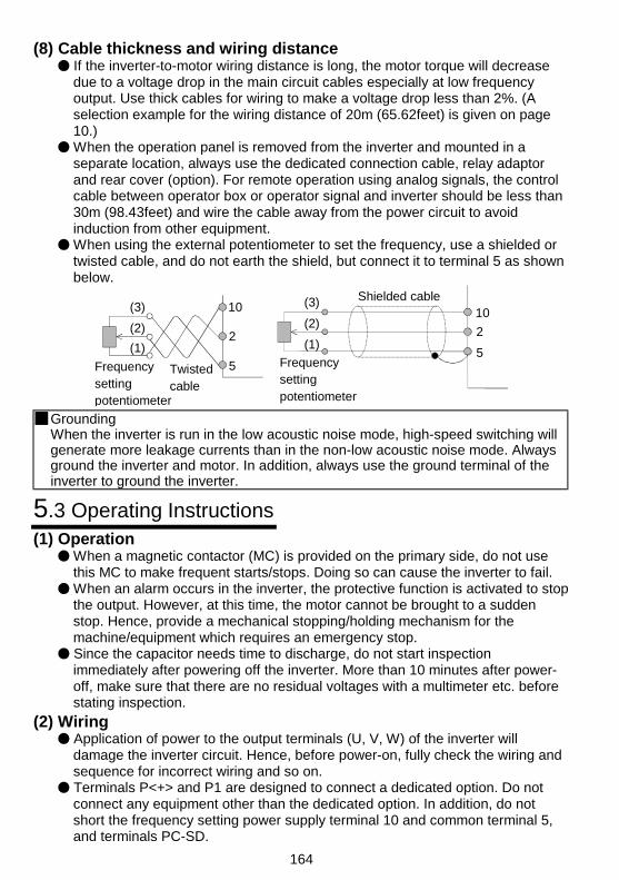
164
(8) Cable thickness and wiring distance If the inverter-to-motor wiring distance is long, the motor torque will decreasedue to a voltage drop in the main circuit cables especially at low frequencyoutput. Use thick cables for wiring to make a voltage drop less than 2%. (Aselection example for the wiring distance of 20m (65.62feet) is given on page10.) When the operation panel is removed from the inverter and mounted in aseparate location, always use the dedicated connection cable, relay adaptorand rear cover (option). For remote operation using analog signals, the controlcable between operator box or operator signal and inverter should be less than30m (98.43feet) and wire the cable away from the power circuit to avoidinduction from other equipment. When using the external potentiometer to set the frequency, use a shielded ortwisted cable, and do not earth the shield, but connect it to terminal 5 as shownbelow.
Twisted cable
Frequency setting potentiometer
(3)
(1)
(2)
10
2
5
Frequency setting potentiometer
Shielded cable(3)
(2)
(1)
10
2
5
GroundingWhen the inverter is run in the low acoustic noise mode, high-speed switching willgenerate more leakage currents than in the non-low acoustic noise mode. Alwaysground the inverter and motor. In addition, always use the ground terminal of theinverter to ground the inverter.
5.3 Operating Instructions(1) Operation
When a magnetic contactor (MC) is provided on the primary side, do not usethis MC to make frequent starts/stops. Doing so can cause the inverter to fail. When an alarm occurs in the inverter, the protective function is activated to stopthe output. However, at this time, the motor cannot be brought to a suddenstop. Hence, provide a mechanical stopping/holding mechanism for themachine/equipment which requires an emergency stop. Since the capacitor needs time to discharge, do not start inspectionimmediately after powering off the inverter. More than 10 minutes after power-off, make sure that there are no residual voltages with a multimeter etc. beforestating inspection.
(2) Wiring Application of power to the output terminals (U, V, W) of the inverter willdamage the inverter circuit. Hence, before power-on, fully check the wiring andsequence for incorrect wiring and so on. Terminals P<+> and P1 are designed to connect a dedicated option. Do notconnect any equipment other than the dedicated option. In addition, do notshort the frequency setting power supply terminal 10 and common terminal 5,and terminals PC-SD.
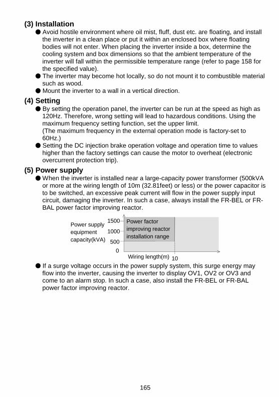
165
(3) Installation Avoid hostile environment where oil mist, fluff, dust etc. are floating, and installthe inverter in a clean place or put it within an enclosed box where floatingbodies will not enter. When placing the inverter inside a box, determine thecooling system and box dimensions so that the ambient temperature of theinverter will fall within the permissible temperature range (refer to page 158 forthe specified value). The inverter may become hot locally, so do not mount it to combustible materialsuch as wood. Mount the inverter to a wall in a vertical direction.
(4) Setting By setting the operation panel, the inverter can be run at the speed as high as120Hz. Therefore, wrong setting will lead to hazardous conditions. Using themaximum frequency setting function, set the upper limit.(The maximum frequency in the external operation mode is factory-set to60Hz.) Setting the DC injection brake operation voltage and operation time to valueshigher than the factory settings can cause the motor to overheat (electronicovercurrent protection trip).
(5) Power supply When the inverter is installed near a large-capacity power transformer (500kVAor more at the wiring length of 10m (32.81feet) or less) or the power capacitor isto be switched, an excessive peak current will flow in the power supply inputcircuit, damaging the inverter. In such a case, always install the FR-BEL or FR-BAL power factor improving reactor.
1500
1000
500
0
Wiring length(m) 10
Power supply equipment capacity(kVA)
Power factor improving reactor installation range
If a surge voltage occurs in the power supply system, this surge energy mayflow into the inverter, causing the inverter to display OV1, OV2 or OV3 andcome to an alarm stop. In such a case, also install the FR-BEL or FR-BALpower factor improving reactor.

166
APPENDIX 1 PARAMETER DATA CODE LIST......167
APPENDIX
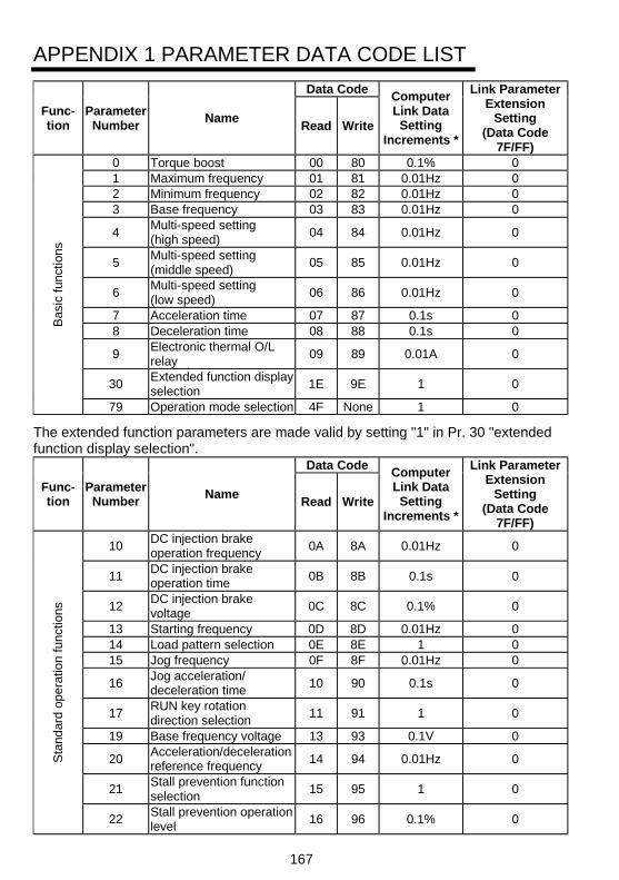
167
APPENDIX 1 PARAMETER DATA CODE LIST
Data Code
Func-tion
ParameterNumber
NameRead Write
ComputerLink DataSetting
Increments *
Link ParameterExtension
Setting(Data Code
7F/FF)0 Torque boost 00 80 0.1% 01 Maximum frequency 01 81 0.01Hz 02 Minimum frequency 02 82 0.01Hz 03 Base frequency 03 83 0.01Hz 0
4Multi-speed setting(high speed)
04 84 0.01Hz 0
5Multi-speed setting(middle speed)
05 85 0.01Hz 0
6Multi-speed setting(low speed)
06 86 0.01Hz 0
7 Acceleration time 07 87 0.1s 08 Deceleration time 08 88 0.1s 0
9Electronic thermal O/Lrelay
09 89 0.01A 0
30Extended function displayselection
1E 9E 1 0
Bas
ic f
unct
ions
79 Operation mode selection 4F None 1 0
The extended function parameters are made valid by setting "1" in Pr. 30 "extendedfunction display selection".
Data Code
Func-tion
ParameterNumber
NameRead Write
ComputerLink DataSetting
Increments *
Link ParameterExtension
Setting(Data Code
7F/FF)
10DC injection brakeoperation frequency
0A 8A 0.01Hz 0
11DC injection brakeoperation time
0B 8B 0.1s 0
12DC injection brakevoltage
0C 8C 0.1% 0
13 Starting frequency 0D 8D 0.01Hz 014 Load pattern selection 0E 8E 1 015 Jog frequency 0F 8F 0.01Hz 0
16Jog acceleration/deceleration time
10 90 0.1s 0
17RUN key rotationdirection selection
11 91 1 0
19 Base frequency voltage 13 93 0.1V 0
20Acceleration/decelerationreference frequency
14 94 0.01Hz 0
21Stall prevention functionselection
15 95 1 0
Sta
ndar
d op
erat
ion
func
tions
22Stall prevention operationlevel
16 96 0.1% 0
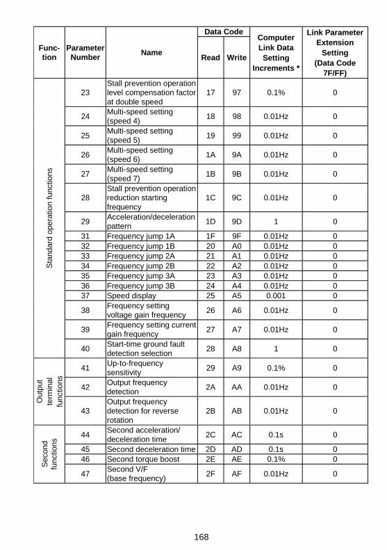
168
Data Code
Func-tion
ParameterNumber
NameRead Write
ComputerLink DataSetting
Increments *
Link ParameterExtension
Setting(Data Code
7F/FF)
23Stall prevention operationlevel compensation factorat double speed
17 97 0.1% 0
24Multi-speed setting(speed 4)
18 98 0.01Hz 0
25Multi-speed setting(speed 5)
19 99 0.01Hz 0
26Multi-speed setting(speed 6)
1A 9A 0.01Hz 0
27Multi-speed setting(speed 7)
1B 9B 0.01Hz 0
28Stall prevention operationreduction startingfrequency
1C 9C 0.01Hz 0
29Acceleration/decelerationpattern
1D 9D 1 0
31 Frequency jump 1A 1F 9F 0.01Hz 032 Frequency jump 1B 20 A0 0.01Hz 033 Frequency jump 2A 21 A1 0.01Hz 034 Frequency jump 2B 22 A2 0.01Hz 035 Frequency jump 3A 23 A3 0.01Hz 036 Frequency jump 3B 24 A4 0.01Hz 037 Speed display 25 A5 0.001 0
38Frequency settingvoltage gain frequency
26 A6 0.01Hz 0
39Frequency setting currentgain frequency
27 A7 0.01Hz 0
Sta
ndar
d op
erat
ion
func
tions
40Start-time ground faultdetection selection
28 A8 1 0
41Up-to-frequencysensitivity
29 A9 0.1% 0
42Output frequencydetection
2A AA 0.01Hz 0
Out
put
term
inal
func
tions
43Output frequencydetection for reverserotation
2B AB 0.01Hz 0
44Second acceleration/deceleration time
2C AC 0.1s 0
45 Second deceleration time 2D AD 0.1s 046 Second torque boost 2E AE 0.1% 0
Sec
ond
func
tions
47Second V/F(base frequency)
2F AF 0.01Hz 0
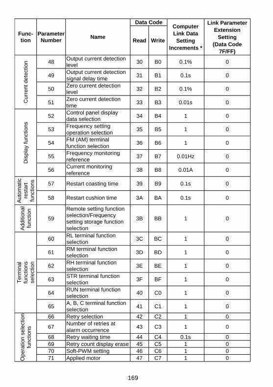
169
Data Code
Func-tion
ParameterNumber
NameRead Write
ComputerLink DataSetting
Increments *
Link ParameterExtension
Setting(Data Code
7F/FF)
48Output current detectionlevel
30 B0 0.1% 0
49Output current detectionsignal delay time
31 B1 0.1s 0
50Zero current detectionlevel
32 B2 0.1% 0
Cur
rent
det
ectio
n
51Zero current detectiontime
33 B3 0.01s 0
52Control panel displaydata selection
34 B4 1 0
53Frequency settingoperation selection
35 B5 1 0
54FM (AM) terminalfunction selection
36 B6 1 0
55Frequency monitoringreference
37 B7 0.01Hz 0
Dis
play
fun
ctio
ns
56Current monitoringreference
38 B8 0.01A 0
57 Restart coasting time 39 B9 0.1s 0
Aut
omat
icre
star
tfu
nctio
ns
58 Restart cushion time 3A BA 0.1s 0
Add
ition
alfu
nctio
n
59
Remote setting functionselection/Frequencysetting storage functionselection
3B BB 1 0
60RL terminal functionselection
3C BC 1 0
61RM terminal functionselection
3D BD 1 0
62RH terminal functionselection
3E BE 1 0
63STR terminal functionselection
3F BF 1 0
64RUN terminal functionselection
40 C0 1 0
Ter
min
alfu
nctio
nsse
lect
ion
65A, B, C terminal functionselection
41 C1 1 0
66 Retry selection 42 C2 1 0
67Number of retries atalarm occurrence
43 C3 1 0
68 Retry waiting time 44 C4 0.1s 069 Retry count display erase 45 C5 1 070 Soft-PWM setting 46 C6 1 0
Ope
ratio
n se
lect
ion
func
tions
71 Applied motor 47 C7 1 0
170
Data Code
Func-tion
ParameterNumber
NameRead Write
ComputerLink DataSetting
Increments *
Link ParameterExtension
Setting(Data Code
7F/FF)72 PWM frequency selection 48 C8 1 073 0-5V/0-10V selection 49 C9 1 074 Input filter time constant 4A CA 1 0
75Reset selection/PU stopselection
4B CB 1 0
76Cooling fan operationselection
4C CC 1 0
77Parameter write disableselection
4D None 1 0
Ope
ratio
n se
lect
ion
func
tions
78Reverse rotationprevention selection
4E CE 1 0
80Multi-speed setting(speed 8)
50 D0 0.01Hz 0
81Multi-speed setting(speed 9)
51 D1 0.01Hz 0
82Multi-speed setting(speed 10)
52 D2 0.01Hz 0
83Multi-speed setting(speed 11)
53 D3 0.01Hz 0
84Multi-speed setting(speed 12)
54 D4 0.01Hz 0
85Multi-speed setting(speed 13)
55 D5 0.01Hz 0
86Multi-speed setting(speed 14)
56 D6 0.01Hz 0
Mul
ti-sp
eed
oper
atio
n
87Multi-speed setting(speed 15)
57 D7 0.01Hz 0
88 PID action selection 58 D8 1 089 PID proportional band 59 D9 0.1% 090 PID integral time 5A DA 0.1s 091 PID upper limit 5B DB 0.1% 092 PID lower limit 5C DC 0.1% 0
93PID action set point forPU operation
5D DD 0.01% 0PID
con
trol
94 PID differential time 5E DE 0.01s 095 Rated motor slip 5F DF 0.01% 0
96Slip compensation timeconstant
60 E0 0.01s 0
97Constant-output regionslip compensationselection
61 E1 1 0
98Automatic torque boostselection(Motor capacity)
62 E2 0.01kW 0Sub
fun
ctio
ns
99 Motor primary resistance 63 E3 0.001Ω 0
171
Data Code
Func-tion
ParameterNumber
NameRead Write
ComputerLink DataSetting
Increments *
Link ParameterExtension
Setting(Data Code
7F/FF)C1 (900(901))
FM (AM) terminalcalibration 5C DC 1
C2 (902)Frequency settingvoltage bias frequency 5E DE 0.01Hz
1(6C/EC=0)
C3 (902)Frequency settingvoltage bias
5E DE 0.1%1
(6C/EC=1)
C4 (903)Frequency settingvoltage gain 5F DF 0.1%
1(6C/EC=1)
C5 (904)Frequency setting currentbias frequency 60 E0 0.01Hz
1(6C/EC=0)
C6 (904)Frequency setting currentbias 60 E0 0.1%
1(6C/EC=1)
C7 (905)Frequency setting currentgain 61 E1 0.1%
1(6C/EC=1)
Cal
ibra
tion
para
met
ers
C8 (269) Parameter set by manufacturer. Do not set.
CLr Parameter clear FC 1
Cle
arpa
ram
eter
s
ECL Alarm history clear F4 1
n1 (331)Communication stationnumber 1F 9F 1 3
n2 (332) Communication speed 20 A0 1 3n3 (333) Stop bit length 21 A1 1 3
n4 (334)Parity checkpresence/absence 22 A2 1 3
n5 (335)Number ofcommunication retries 23 A3 1 3
n6 (336)Communication checktime interval 24 A4 0.1s 3
n7 (337) Wait time setting 25 A5 1 3n8 (338) Operation command write 26 A6 1 3n9 (339) Speed command write 27 A7 1 3
n10 (340) Link start mode selection 28 A8 1 3n11 (341) CR/LF selection 29 A9 1 3
n12 (342) E2PROM write selection 2A AA 1 3
n13 (145) PU display language 2D AD 1 1n14 (990) PU buzzer sound control 5A DA 1 9n15 (991) PU contrast adjustment 5B DB 1 9
n16 (992)PU main display screendata selection 5C DC 1 9
Com
mun
icat
ion
par
amet
ers
n17 (993)PU disconnectiondetection/PU setting lock
5D DD 1 9
The parameter numbers within parentheses are those for use of the parameter unit(FR-PU04).* Though parameter setting by RS-485 communication can be made in the setting
increments indicated in the table, note that the valid setting increments are asindicated in the parameter list (page 41).

REVISIONS*The manual number is given on the bottom left of the back cover.
Print Date *Manual Number Revision
Mar, 2000 IB(NA)-0600027-A First edition