FORD KUGA - Carpratik
7
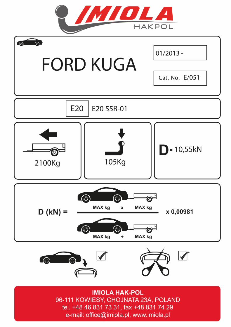
Cat. No. 2100Kg 105Kg 01/2013 - E/051 10,55kN E20 55R-01 D (kN) = MAX kg MAX kg MAX kg MAX kg x + x 0,00981 D = FORD KUGA E20
Transcript of FORD KUGA - Carpratik
Cat. No.
2100Kg 105Kg
01/2013 -
E/051
10,55kN
E20 55R-01
D (kN) = MAX kg MAX kg
MAX kg MAX kg
x
+
x 0,00981
D =
FORD KUGA
E20
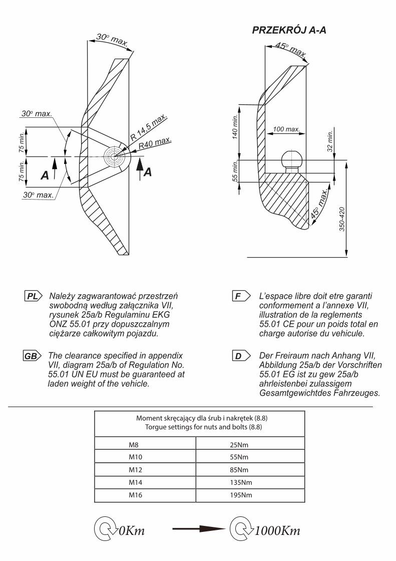
0Km 1000Km
Moment skręcający dla śrub i nakrętek (8.8) Torgue settings for nuts and bolts (8.8)
M8
M10
M12
M14
M16
25Nm
55Nm
85Nm
135Nm
195Nm
R 14,5 max.
30o max.
30o max.
R40 max.
75 m
in.
75 m
in.
AA
100 max.
140
min
.
PRZEKRÓJ A-A
55 m
in.
32 m
in.
350-
420
PL Należy zagwarantować przestrzeńswobodną według załącznika VII,rysunek 25a/b Regulaminu EKGONZ 55.01 przy dopuszczalnym ciężarze całkowitym pojazdu.
L’espace libre doit etre garanticonformement a l’annexe VII,illustration de la reglements 55.01 CE pour un poids total en charge autorise du vehicule.
The clearance specified in appendix VII, diagram 25a/b of Regulation No.55.01 UN EU must be guaranteed atladen weight of the vehicle.
Der Freiraum nach Anhang VII, Abbildung 25a/b der Vorschriften 55.01 EG ist zu gew 25a/b ahrleistenbei zulassigem Gesamtgewichtdes Fahrzeuges.
GB
F
D
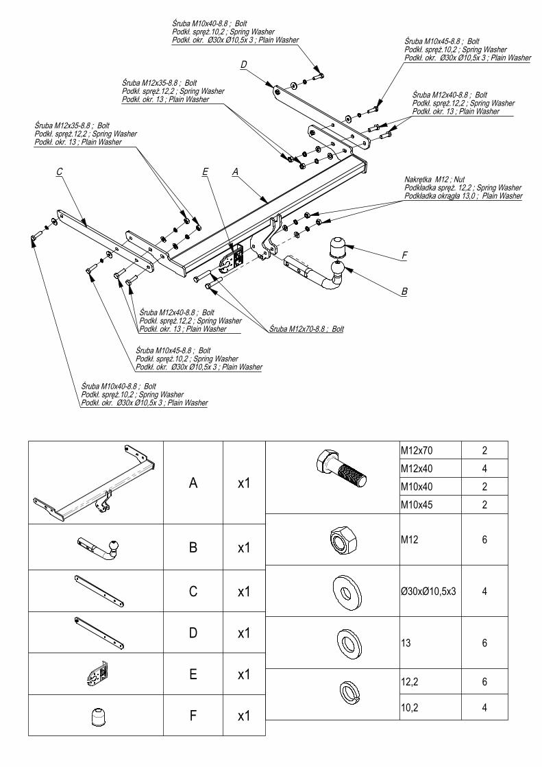
x1
x1
x1
x1
x1
x1
M12x70 2M12x40 4M10x40 2M10x45 2
M12
Ø30xØ10,5x3 4
13
12,2
10,2 4
A
B
C
D
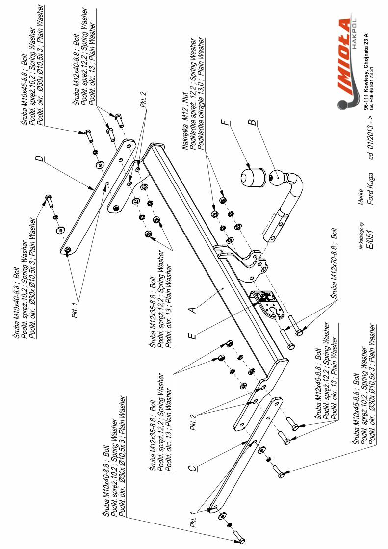
Pkt. 1
Pkt. 1
Pkt. 2
Pkt. 2
E
F
E/05
1Ma
rkaod
01/2
013 -
>Fo
rd K
uga
96-1
11 K
owie
sy, C
hojn
ata
23 A
tel.
+48
46 8
31 7
3 31
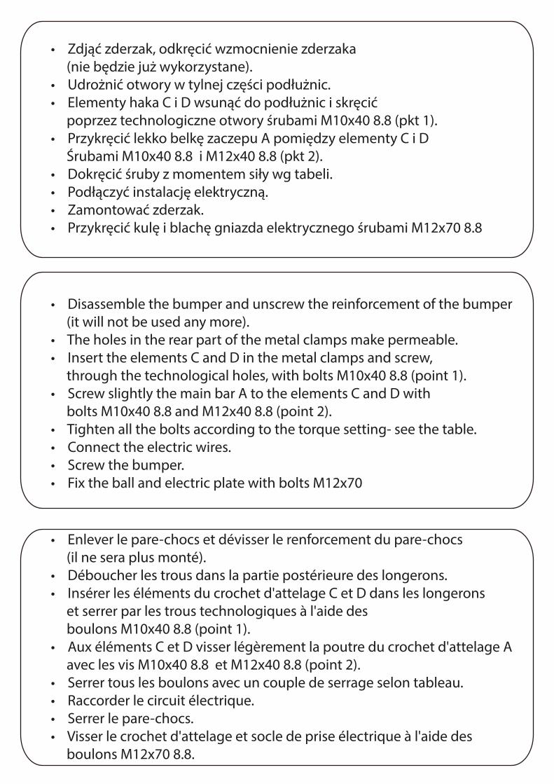
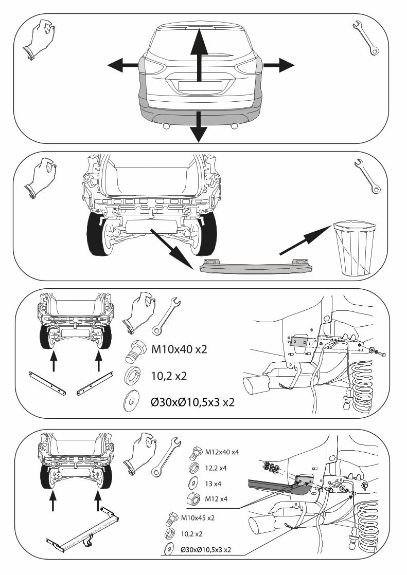
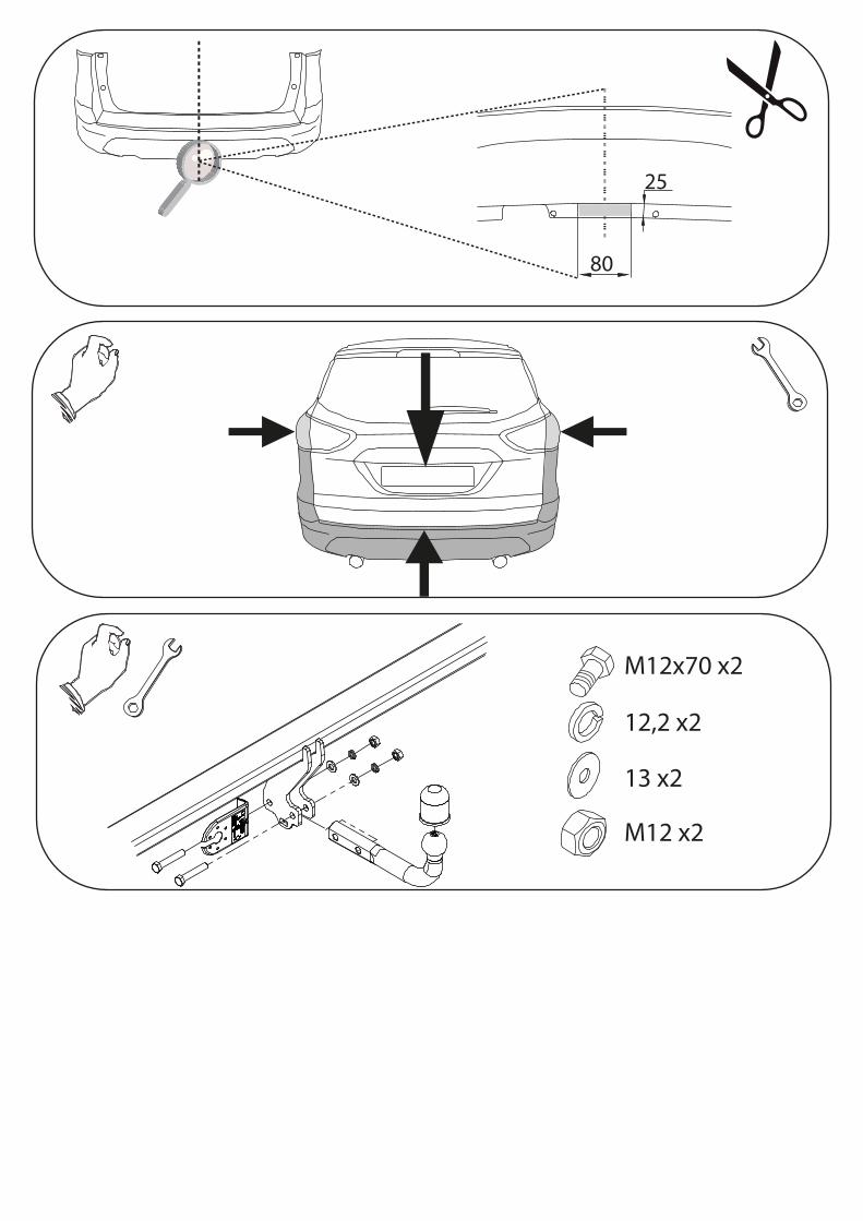
• Zdjąć zderzak, odkręcić wzmocnienie zderzaka (nie będzie już wykorzystane).• Udrożnić otwory w tylnej części podłużnic.• Elementy haka C i D wsunąć do podłużnic i skręcić poprzez technologiczne otwory śrubami M10x40 8.8 (pkt 1).• Przykręcić lekko belkę zaczepu A pomiędzy elementy C i D Śrubami M10x40 8.8 i M12x40 8.8 (pkt 2).• Dokręcić śruby z momentem siły wg tabeli.• Podłączyć instalację elektryczną.• Zamontować zderzak.• Przykręcić kulę i blachę gniazda elektrycznego śrubami M12x70 8.8
• Disassemble the bumper and unscrew the reinforcement of the bumper (it will not be used any more).• The holes in the rear part of the metal clamps make permeable.• Insert the elements C and D in the metal clamps and screw, through the technological holes, with bolts M10x40 8.8 (point 1).• Screw slightly the main bar A to the elements C and D with bolts M10x40 8.8 and M12x40 8.8 (point 2).• Tighten all the bolts according to the torque setting- see the table.• Connect the electric wires.• Screw the bumper.• Fix the ball and electric plate with bolts M12x70
• Enlever le pare-chocs et dévisser le renforcement du pare-chocs (il ne sera plus monté).• Déboucher les trous dans la partie postérieure des longerons.• Insérer les éléments du crochet d'attelage C et D dans les longerons et serrer par les trous technologiques à l'aide des boulons M10x40 8.8 (point 1).• Aux éléments C et D visser légèrement la poutre du crochet d'attelage A avec les vis M10x40 8.8 et M12x40 8.8 (point 2).• Serrer tous les boulons avec un couple de serrage selon tableau.• Raccorder le circuit électrique.• Serrer le pare-chocs.• Visser le crochet d'attelage et socle de prise électrique à l'aide des boulons M12x70 8.8.
M10x40 x2
10,2 x2
Ø30xØ10,5x3 x2
M10x45 x2
10,2 x2
Ø30xØ10,5x3 x2
M12x40 x4
12,2 x4
13 x4
M12 x4
M12x70 x2
12,2 x2
13 x2
M12 x2
80
25