European Technical Approval ETA-11/0507 - Diager · in masonry , ETAG 029. ... (use category c)...
16
Europejska Organizacja ds. Aprobat Technicznych European Organisation for Technical Approvals INSTYTUT TECHNIKI BUDOWLANEJ PL 00-611 WARSZAWA ul. FILTROWA 1 tel.: (48 22) 825-04-71; (48 22) 825-76-55; fax: (48 22) 825-52-86; www.itb.pl European Technical Approval ETA-11/0507 English language translation - the original version is in Polish language Nazwa handlowa Polyester V300 & V410 / Polyester P165 Trade name Polyester V300 & V410 / Polyester P165 Wlaściciel aprobaty Holder of approval DIAGER Rue Henri Moissan, BP90149 F-39802 Poligny France Rodzaj i przeznaczenie wyrobu Kotwy wklejane do wykonywania zamocowań w podloŜu murowym Generic type and use of construction products Injection anchor for use in masonry Termin waŜności od Valid from do to 09. 12. 2011 31. 03. 2016 Zaklad produkcyjny Manufacturing plant FRANCE 1 Niniejsza Europejska Aprobata Techniczna zawiera 16 stron, w tym 8 Zalączników This European Technical Approval contains 16 pages including 8 Annexes Czlonek EOTA
Transcript of European Technical Approval ETA-11/0507 - Diager · in masonry , ETAG 029. ... (use category c)...
Europejska Organizacja ds. Aprobat Technicznych
European Organisation for Technical Approvals
INSTYTUT TECHNIKI BUDOWLANEJ PL 00-611 WARSZAWA ul. FILTROWA 1 tel.: (48 22) 825-04-71; (48 22) 825-76-55; fax: (48 22) 825-52-86; www.itb.pl
European Technical Approval ETA-11/0507 English language translation - the original version is in Polish language
Nazwa handlowa Polyester V300 & V410 / Polyester P165 Trade name Polyester V300 & V410 / Polyester P165
Właściciel aprobaty Holder of approval
DIAGER Rue Henri Moissan, BP90149 F-39802 Poligny France
Rodzaj i przeznaczenie wyrobu Kotwy wklejane do wyk onywania zamocowa ń w podło Ŝu murowym
Generic type and use of construction products
Injection anchor for use in masonry
Termin wa Ŝności od Valid from do to
09. 12. 2011
31. 03. 2016
Zakład produkcyjny Manufacturing plant
FRANCE 1
Niniejsza Europejska Aprobata Techniczna zawiera 16 stron, w tym 8 Zał ączników
This European Technical Approval contains
16 pages including 8 Annexes
Członek EOTA
Page 2 of European Technical Approval ETA-11/0507, issued on 09.12.2011 English translation prepared by Instytut Techniki Budowlanej
I LEGAL BASES AND GENERAL CONDITIONS
1. This European Technical Approval is issued by Instytut Techniki Budowlanej in accordance with:
– Council Directive 89/106/EEC of 21 December 1988 on the approximation of laws, regulations and administrative provisions of Member States relating to construction products1, amended by the Council Directive 93/68/EEC of 22 July 19932;
– ustawa z dnia 16 kwietnia 2004 r. o wyrobach budowlanych (law on construction products from 16th April 2004)3;
– rozporządzenie Ministra Infrastruktury z dnia 14 października 2004 r. w sprawie europejskich aprobat technicznych oraz polskich jednostek organizacyjnych upowaŜnionych do ich wydawania (regulation of Ministry of Infrastructure of 14th October 2004 on the European Technical Approvals and Polish bodies entitled to issue them)4;
– Common Procedural Rules for Requesting, Preparing and the Granting of European Technical Approvals set out in the Annex of Commission Decision 94/23/EC5;
– Guideline for European Technical Approval of „Metal injection anchors for use in masonry, ETAG 029.
2. Instytut Techniki Budowlanej is authorized to check whether the provisions of this European Technical Approval are met. Checking may take place in the manufacturing plant. Nevertheless, the responsibility for the conformity of the products to the European Technical Approval and for their fitness for the intended use remains with the holder of the European Technical Approval.
3. This European Technical Approval is not to be transferred to manufacturers or agents of manufacturers other than those indicated on page 1, or manufacturing plants other than those indicated on page 1 of this European Technical Approval.
4. This European Technical Approval may be withdrawn by Instytut Techniki Budowlanej, in particular after information by the Commission on the basis of Article 5 (1) of Council Directive 89/106/EEC.
5. Reproduction of this European Technical Approval including transmission by electronic means shall be in full. However, partial reproduction can be made with the written consent of Instytut Techniki Budowlanej. In this case partial reproduction has to be designated as such. Texts and drawings of advertising brochures shall not contradict or misuse the European Technical Approval.
6. The European Technical Approval is issued by the approval body in its official language. This version corresponds to the version circulated within EOTA. Translations into other languages have to be designated as such.
1 Official Journal of the European Communities № L 40, 11.02.1989, p. 12 2 Official Journal of the European Communities № L 220, 30.08.1993, p. 1 3 Official Journal of Polish Republic № 92/2004, pos. 881 4 Official Journal of Polish Republic № 237/2004, pos. 2375 5 Official Journal of the European Communities № L 17, 20.01.1994, p. 34
Page 3 of European Technical Approval ETA-11/0507, issued on 09.12.2011 English translation prepared by Instytut Techniki Budowlanej
II SPECIFIC CONDITIONS OF THE EUROPEAN TECHNICAL APPROVAL
1 Definition of the product and intended use
1.1 Definition of the construction product
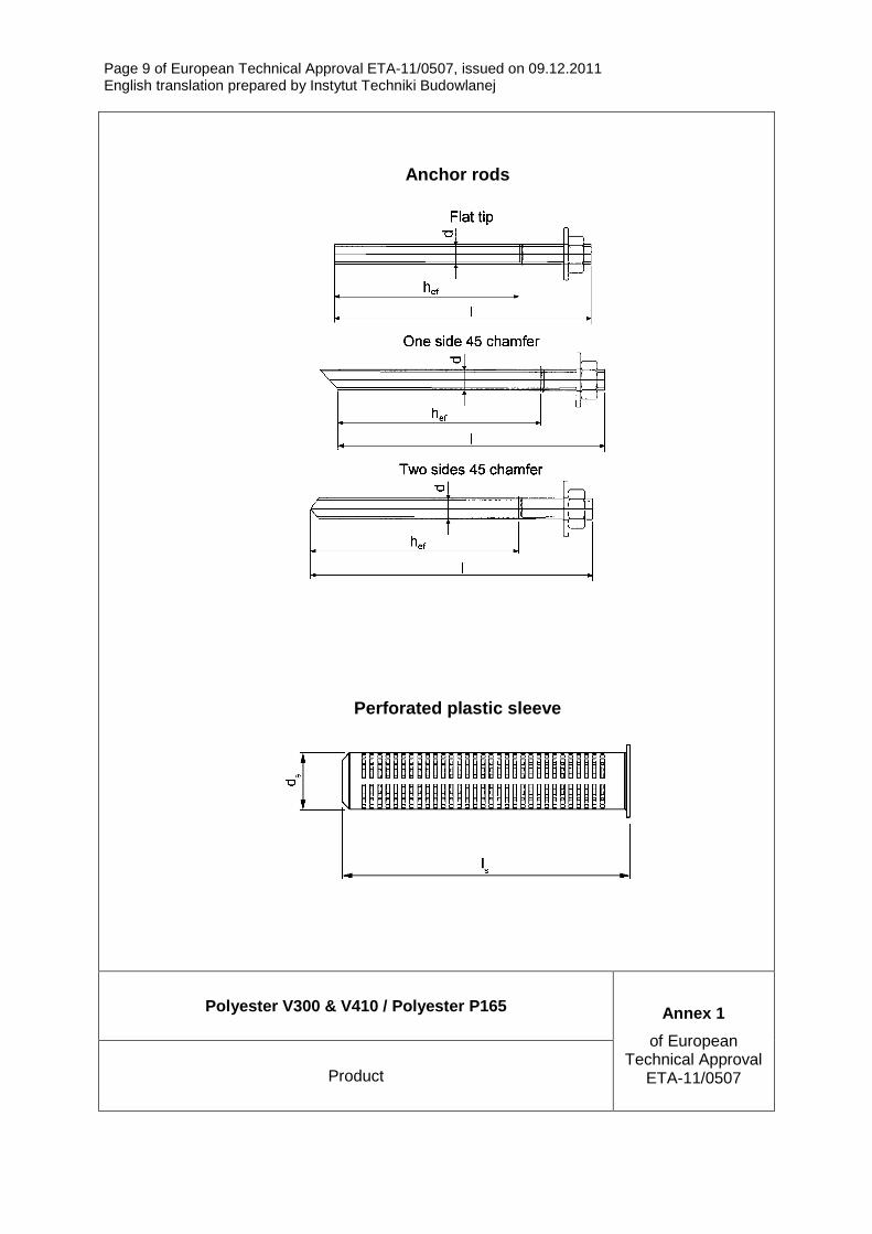
The injection anchor Polyester V300 & V410 / Polyester P165 is a bonded anchor (injection type) consisting of a cartridge with Polyester V300 & V410 / Polyester P165 injection mortar, a perforated sleeve φ16 x 85 and an anchor rod with hexagon nut and washer size M10. The steel elements are made of zinc coated carbon steel.
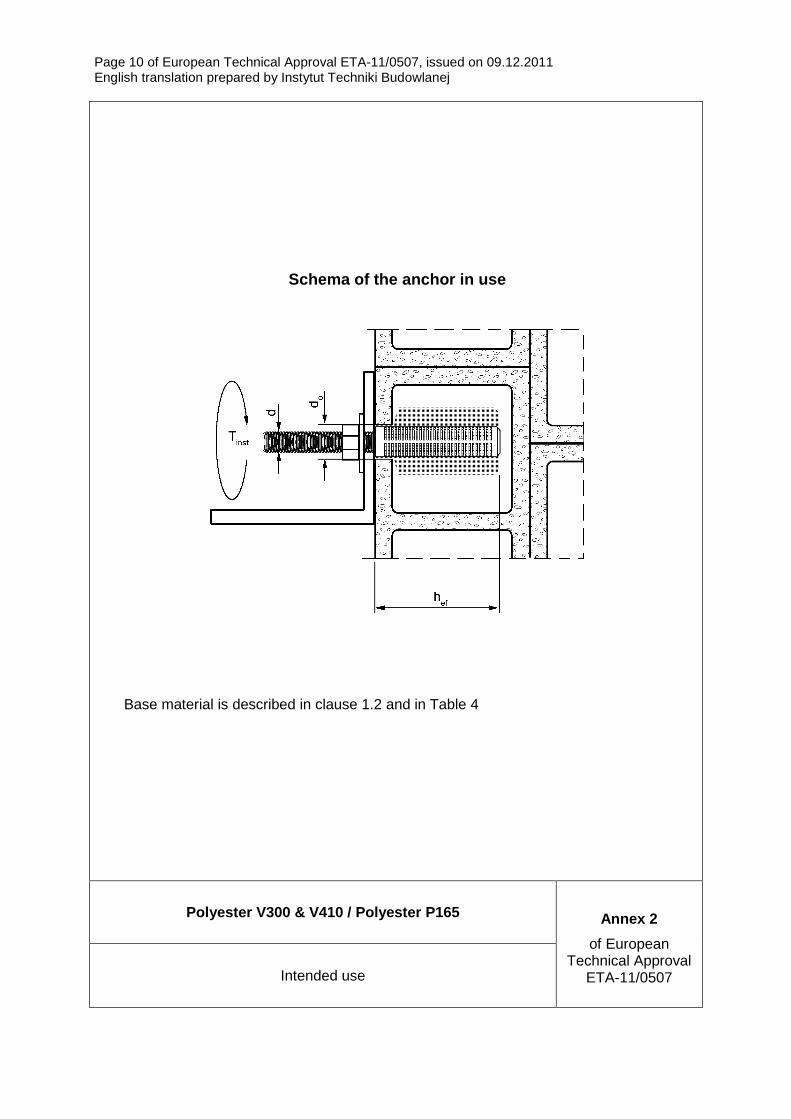
The anchor rod is placed into a drilled hole filled with injection mortar and is anchored via the bond between steel element, injection mortar and masonry.
An illustration of the product and intended use is given in Annexes 1 and 2.
1.2 Intended use
The anchor is intended to be used for anchorages for which requirements for mechanical resistance and stability and safety in use in the sense of the Essential Requirements 1 and 4 of Council Directive 89/106/EEC shall be fulfilled and failure of anchorages made with these products would cause risk to human life and/or lead to considerable economic consequences.
The anchor is to be used only for anchorages subject to static or quasi-static loading in perforated masonry (use category c) according to Annex 6. The mortar strength class of the masonry has to be M 2,5 according to EN 998-2 at minimum. The anchor may be installed in wet substrate and use in structures subject to dry, internal conditions (category w/d).
The anchor may be used in the following service temperature range: -40oC to +80oC (max long term temperature +50oC and max short term temperature +80oC).
The element made of electroplated or hot-dipped galvanised steel may only be used in structures subject to dry internal conditions.
The provisions made in this European Technical Approval are based on an assumed working life of the anchor of 50 years. The indications given on the working life cannot be interpreted as a guarantee given by the producer, or by the Approval Body, but are to be regarded only as a means for choosing the right products in relation to the expected economically reasonable working life of the works.
2 Characteristics of the product and methods of ver ification
2.1 Characteristics of the product
The anchors corresponds to the drawings and provisions given in Annexes 1 to 6. The characteristic material values, dimensions and tolerances of the anchor not
Page 4 of European Technical Approval ETA-11/0507, issued on 09.12.2011 English translation prepared by Instytut Techniki Budowlanej
indicated in Annexes shall correspond to the respective values laid down in the technical documentation6 of this European Technical Approval.
The characteristic anchor values for the design of the anchorages are given in Annexes 7 and 8.
The metal parts of the injection anchor are assumed to satisfy the requirements for class A1 of the characteristic reaction to fire in accordance with the provisions of EC decision 96/603/EC, amended by 2000/605/EC. In the end use application the bonding material in connection with the injection anchor does not make any contribution to fire growth or to the fully developed fire and they have no influence to the smoke hazard. Regarding resistance to fire no performance is determined.
2.2 Methods of verification
The assessment of fitness of the anchor for the intended use in relation to the requirements for mechanical resistance and stability and safety in use in the sense of the Essential Requirement 1 and 4 has been made in accordance with the “Guideline for European Technical Approval of “Metal injection anchors for use in masonry”, ETAG 029, based on the use category c in respect of the base material and category w/d in respect of installation and use.
In addition to the specific clauses relating to dangerous substances contained in this ETA, there may be other requirements applicable to the products falling within its scope (e.g. transposed European legislation and national laws, regulations and administrative provisions). In order to meet the provisions of the Construction Products Directive, these requirements need also to be complied with, when and where they apply.
3 Evaluation of Conformity and CE-marking
3.1 Attestation of Conformity System
According to the Decision 97/177/EC of the European Commission7 system 1 of attestation of conformity applies.
This system of attestation of conformity is defined as follows:
System 1: Certification of conformity of the product by an approved certification body on the basis of:
(a) Tasks for the manufacturer:
(1) factory production control,
(2) further testing of samples taken at the factory by the manufacturer in accordance with a prescribed test plan,
(b) Tasks for the approved body:
(3) initial type-testing of the product,
(4) initial inspection of factory and of factory production control,
(5) continuous surveillance, assessment and approval of factory production control.
6 The technical documentation of this European Technical Approval is deposited at Instytut Techniki Budowlanej
and, as far as relevant for the tasks of the approved bodies involved in the attestation of conformity procedure, is handed over to the approved body involved.
7 Official Journal of the European Communities L 073 of 14.03.1997
Page 5 of European Technical Approval ETA-11/0507, issued on 09.12.2011 English translation prepared by Instytut Techniki Budowlanej
3.2 Responsibilities
3.2.1 Tasks for the manufacturer
3.2.1.1 Factory production control
The manufacturer shall exercise permanent internal control of production. All the elements, requirements and provisions adopted by the manufacturer shall be documented in a systematic manner in the form of written policies and procedures, including records of results performed. This production control system shall insure that the product is in conformity with this European Technical Approval.
The manufacturer may only use raw materials stated in the technical documentation of this European Technical Approval.
The factory production control shall be in accordance with the control plan8 which is part of the technical documentation of this European Technical Approval. The control plan is laid down in the context of the factory production control system operated by the manufacturer and deposited at Instytut Techniki Budowlanej.
The results of factory production control shall be recorded and evaluated in accordance with the provisions of the control plan.
3.2.1.2 Other tasks for the manufacturer
The manufacturer shall, on the basis of a contract, involve a body which is approved for the tasks referred to in section 3.1 in the field of anchors in order to undertake the actions laid down in section 3.2.2. For this purpose, the control plan referred to in section 3.2.1.1 and 3.2.2 shall be handed over by the manufacturer to the approved body involved.
The manufacturer shall make a declaration of conformity, stating that the construction product is in conformity with the provisions of this European Technical Approval.
3.2.2 Tasks for the approved body
3.2.2.1 Initial type-testing of the product
For initial type-testing the results of the tests performed as part of the assessment for the European Technical Approval shall be used unless there are changes in the production line or plant. In such cases the necessary initial type-testing has to be agreed between the Instytut Techniki Budowlanej and the approved body involved.
3.2.2.2 Initial inspection of factory and of factory production control
The approved body shall ascertain that, in accordance with the control plan, the factory, in particular the staff and equipment, and the factory production control are suitable to ensure continuous and orderly manufacturing of the anchor according to the specifications mentioned in clause 2.1 as well as to the Annexes to this European Technical Approval.
3.2.2.3 Continuous surveillance
Continuous surveillance and assessment of factory production control have to be performed according to the control plan.
8 The control plan has been deposited at Instytut Techniki Budowlanej and may be handed over only to the
approved body involved in the conformity attestation procedure.
Page 6 of European Technical Approval ETA-11/0507, issued on 09.12.2011 English translation prepared by Instytut Techniki Budowlanej
The approved body shall visit the factory at least once a year for surveillance. It has to be verified that the system of factory production control and the specified automated manufacturing process are maintained taking account of the control plan.
The results of continuous surveillance shall be made available on demand by the approved body to Instytut Techniki Budowlanej. In cases where the provisions of the European Technical Approval and the control plan are no longer fulfilled the conformity certificate shall be withdrawn.
3.3 CE-marking
The CE-marking shall be affixed on each packaging of the anchor. The letters „CE” shall be accompanied by the following additional information:
– the identification number of the approved certification body,
– the name and address of the producer (legal entity responsible for the manufacture),
– the last two digits of the year in which the CE-marking was affixed,
– the number of the EC certificate of conformity for the product,
– the number of the European Technical Approval,
– the number of the Guideline for European Technical Approval,
– use category (c and w/d),
– size.
4 Assumptions under which the fitness of the produc t for the intended use was favorably assessed
4.1 Manufacturing
The ETA is issued on the basis of agreed data/information, deposited with Instytut Techniki Budowlanej, which identifies the product that has been assessed and judged. Changes to the product or production process, which could result in this deposited data/information being incorrect, should be notified to Instytut Techniki Budowlanej before the changes are introduced. Instytut Techniki Budowlanej will decide whether or not such changes affect the ETA and consequently the validity of the CE marking on the basis of the ETA and if so whether further assessment or alterations to the ETA shall be necessary.
4.2 Design of anchorages
The fitness of the anchor for the intended use is given under the following conditions:
– the anchorages are designed in accordance with the ETAG 029 „Metal Injection Anchors for Use in Masonry, Annex C: Design methods for anchorages, Design method A” under the responsibility of an engineer experienced in anchorages and masonry work,
– verifiable calculation notes and drawings are prepared taking account the relevant masonry in the region of the anchorage (nature and strength of the base materials), the loads to be transmitted and their transmission to the supports, of the structure.
Page 7 of European Technical Approval ETA-11/0507, issued on 09.12.2011 English translation prepared by Instytut Techniki Budowlanej
– the position of the anchor is indicated on the design drawings (e.g. position of the anchor relative to supports etc.),
– the characteristic resistances for use in perforated masonry are only valid for the blocks according to Annex 6 regarding base material, size of the units, compressive strength and configuration of the voids,
– for smaller block sizes or smaller compressive strength or different blocks in perforated masonry on the construction site, the characteristic resistance of the anchor may be determined by job site tests according to ETAG 029 ”Metal Injection Anchors for Use in Masonry, Annex B: Recommendations for tests to be carried out on construction works”.
4.3 Installation
The fitness for use of the anchor can only be assumed if the anchor is installed as follows:
– anchor installation carried out by appropriately qualified personnel and under the supervision of the person responsible for technical matters of the site,
– use of the anchor only as supplied by the manufacturer without exchanging the component of the anchor,
– commercial standard threaded rods, washers and hexagon nuts made of zinc coated steel may also be used if the following requirements are fulfilled:
� material, dimensions and mechanical properties of the metal parts according to the specifications given in Annex 5, Tables 1 and 2.
� confirmation of material and mechanical properties of the metal parts by inspection certificate according to EN 10204, the documents should be stored,
� marking of the threaded rod with the envisage embedment depth. This may be done by the manufacturer of the rod or the person on jobsite,
– anchor installation in accordance with the manufacturer's specifications and drawings using the tools indicated in the technical documentation of this European Technical Approval,
– checks before placing the anchor to ensure that the use category applies and the strength class, density etc. of the base material is not lower than that to which the characteristic loads apply,
– holes to be drilled perpendicular to the surface by using a hard-metal tipped hammer drill bit, with a rotary machine,
– in case of aborted drill hole: the drill hole shall be filled with mortar,
– anchor installation in accordance with manufacturer’s installation instruction (Annex 4),
– keeping the installation parameters (Annex 5),
– keeping edge distance and spacing according to Annex 8 without minus tolerances,
– observing the curing time according to Annex 6, Table 3 until the anchor may be loaded.
Page 8 of European Technical Approval ETA-11/0507, issued on 09.12.2011 English translation prepared by Instytut Techniki Budowlanej
5 Indications to the manufacturer
5.1 Manufacturer’s responsibility
It is in the responsibility of the manufacturer to ensure that the information on the specific conditions according to 1, 2, 4 and 5.2 is given to those who are concerned. This information may be made by reproduction of the respective parts of the European Technical Approval. In addition all installation data shall be shown clearly on the package and/or on an enclosed instruction sheet, preferably using illustration(s).
The minimum data required are:
– installation parameters according to Annex 5,
– material and property class of metal parts according to Annex 5,
– information on the installation procedure, preferably by means of an illustration,
– exact volume of injection mortar depend on the relevant installation,
– cartridge temperature, ambient temperature of the masonry, processing time (working time) of a cartridge and curing time until the anchor may be loaded according to Annex 6,
– identification of the manufacturing batch.
All data shall be presented in a clear and explicit form.
5.2 Recommendations regarding packaging, transport and storage
The injection cartridges shall be protected against sun radiation and shall be stored according to the manufacture’s instruction in dry condition at temperatures of at least +5oC to not more than +25oC.
Mortar cartridges with expired shelf life must no longer be used.
Page 9 of European Technical Approval ETA-11/0507, issued on 09.12.2011 English translation prepared by Instytut Techniki Budowlanej
Polyester V300 & V410 / Polyester P165 Annex 1
of European Technical Approval
ETA-11/0507 Product
Anchor rods
Perforated plastic sleeve
Page 10 of European Technical Approval ETA-11/0507, issued on 09.12.2011 English translation prepared by Instytut Techniki Budowlanej
Polyester V300 & V410 / Polyester P165 Annex 2
of European Technical Approval
ETA-11/0507 Intended use
Schema of the anchor in use
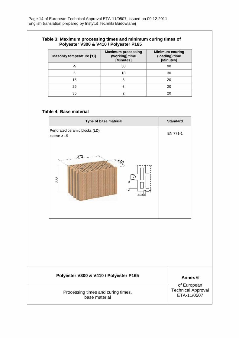
Base material is described in clause 1.2 and in Table 4
Page 11 of European Technical Approval ETA-11/0507, issued on 09.12.2011 English translation prepared by Instytut Techniki Budowlanej
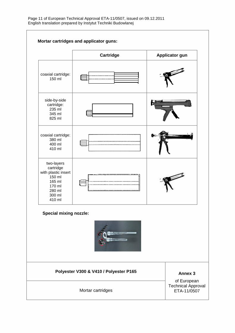
Polyester V300 & V410 / Polyester P165 Annex 3
of European Technical Approval
ETA-11/0507 Mortar cartridges
Mortar cartridges and applicator guns:
Cartridge Applicator gun
coaxial cartridge: 150 ml
side-by-side cartridge:
235 ml 345 ml 825 ml
coaxial cartridge: 380 ml 400 ml 410 ml
two-layers cartridge
with plastic insert 150 ml 165 ml 170 ml 280 ml 300 ml 410 ml
Special mixing nozzle:
Page 12 of European Technical Approval ETA-11/0507, issued on 09.12.2011 English translation prepared by Instytut Techniki Budowlanej
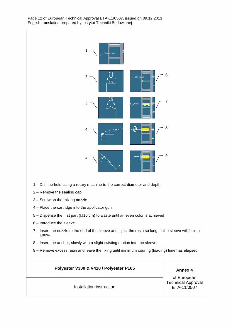
1 – Drill the hole using a rotary machine to the correct diameter and depth
2 – Remove the sealing cap
3 – Screw on the mixing nozzle
4 – Place the cartridge into the applicator gun
5 – Dispense the first part (∼ 10 cm) to waste until an even color is achieved
6 – Introduce the sleeve
7 – Insert the nozzle to the end of the sleeve and inject the resin so long till the sleeve will fill into 100%
8 – Insert the anchor, slowly with a slight twisting motion into the sleeve
9 – Remove excess resin and leave the fixing until minimum couring (loading) time has elapsed
Polyester V300 & V410 / Polyester P165 Annex 4
of European Technical Approval
ETA-11/0507 Installation instruction
1
2
3
4
5
6
7
8
9

Page 13 of European Technical Approval ETA-11/0507, issued on 09.12.2011 English translation prepared by Instytut Techniki Budowlanej
Polyester V300 & V410 / Polyester P165 Annex 5
of European Technical Approval
ETA-11/0507 Installation parameters of anchor rods with perforated sleeves, materials
Table 1: Installation parameters of anchor rods wit h perforated sleeves
Size M10
Size of rod dnom [mm] 10
Size of sleeve ds x ls [mm] 16 x 85
Drill hole diameter do [mm] 16
Depth of drilled hole to deepest point h1 [mm] 90
Effective anchorage depth hef [mm] 85
Torque moment Tinst [Nm] 4
Table 2: Materials
Part Designation Material
1 Chemical mortar Polyester, styrene free resine mortar, hardener, additive
2 Anchor rod Carbon steel class 5.8, EN ISO 898-1, zinc plated ≥ 5 µm, EN ISO 4042
3 Washer Carbon steel, zinc plated ≥ 5 µm, EN ISO 4042
4 Hexagonal nut Carbon steel class 5, EN 20898-2, zinc plated ≥ 5 µm, EN ISO 4042
5 Perforated sleeve Polyethylene
Page 14 of European Technical Approval ETA-11/0507, issued on 09.12.2011 English translation prepared by Instytut Techniki Budowlanej
Polyester V300 & V410 / Polyester P165 Annex 6
of European Technical Approval
ETA-11/0507 Processing times and curing times,
base material
Table 3: Maximum processing times and minimum curin g times of Polyester V300 & V410 / Polyester P16 5
Masonry temperature [°C] Maximum processing
(working) time [Minutes]
Minimum couring (loading) time
[Minutes]
-5 50 90
5 18 30
15 8 20
25 3 20
35 2 20
Table 4: Base material
Type of base material Standard
Perforated ceramic blocks (LD)
classe ≥ 15
EN 771-1
Page 15 of European Technical Approval ETA-11/0507, issued on 09.12.2011 English translation prepared by Instytut Techniki Budowlanej
Polyester V300 & V410 / Polyester P165 Annex 7
of European Technical Approval
ETA-11/0507 Characteristic tension load and shear load values,
characteristic bending moment, displacements
Table 5: Characteristic tension load and shear load values
Brick parameters:
Density q [kg/m 3]
Compressive strength
fb [N/mm 2]
Sleeve Anchor size
Effective anchorage
depth hef [mm]
Characteristic resistance NRk [kN] 1)
Characteristic resistance VRk [kN] 2)
q ≥ 900 16 x 85 M10 85 3,0 3,0
fb ≥ 12
Partial safety factor ϒM = 2,5 3)
1) For design according to ETAG 029, Annex C NRk = NRk,p = NRk,b = NR,pb = NRk,s
2) For design according to ETAG 029, Annex C VRk = VRk,b = VRk,c = VRk,s
3) In absence of other national regulations
Table 6: Characteristic bending moment
Characteristic bending moment MRk,s [Nm] 37,38
Partial safety factor γΜs 1,251)
1) if no other national regulations exist
Table 7: Displacements under tension and shear load
N [kN] δδδδNO [mm] δδδδN∞∞∞∞ [mm] V [kN] δδδδVO [mm] δδδδV∞∞∞∞ [mm]
1,3 0,09 0,15 2,5 0,8 2,5
Page 16 of European Technical Approval ETA-11/0507, issued on 09.12.2011 English translation prepared by Instytut Techniki Budowlanej
Polyester V300 & V410 / Polyester P165 Annex 8
of European Technical Approval
ETA-11/0507 β-factor, edge distances and spacings
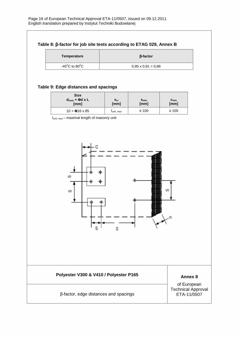
Table 8: ββββ-factor for job site tests according to ETAG 029, A nnex B
Temperature ββββ-factor
-40oC to 80oC 0,95 x 0,91 = 0,86
Table 9: Edge distances and spacings
Size dnom + ΦΦΦΦd x L
[mm]
scr
[mm]
smin
[mm]
cmin
[mm]
10 + ΦΦΦΦ16 x 85 lunit, max ≥ 100 ≥ 100
lunit, max – maximal length of masonry unit


![Edmond Hamilton - Internet Archive · 2010. 6. 11. · by Edmond Hamilton, published by Project Gutenberg, May 10, 2010 [EBook #32317] According to the included copyright notice:](https://static.fdocuments.pl/doc/165x107/60b32ec7a97cb07f186eb0e9/edmond-hamilton-internet-archive-2010-6-11-by-edmond-hamilton-published.jpg)