ETAokladka angielska - AmpeKo-Techampekotech.cz/wp-content/uploads/2014/01/eta-simpson-at-hp... ·...
24
ETA-11/0139 Post-installed rebar connections of the sizes 8 to 32 mm Wklejane zakotwienia prętów zbrojeniowych o średnicach od 8 do 32 mm European Technical Approval Member of EOTA AT-HP for rebar connections
Transcript of ETAokladka angielska - AmpeKo-Techampekotech.cz/wp-content/uploads/2014/01/eta-simpson-at-hp... ·...

ETA-11/0139
Post-installed rebar connectionsof the sizes 8 to 32 mm
Wklejane zakotwienia prętów zbrojeniowycho średnicach od 8 do 32 mm
European Technical Approval
Member of EOTA
AT-HPfor rebar connections
Europejska aprobata techniczna została opracowana w Zakładzie Aprobat Technicznych przez mgr inż. Annę KUKULSKĄ-GRABOWSKĄ Projekt okładki: Ewa Kossakowska GW I Kopiowanie aprobaty technicznej jest dozwolone jedynie w całości Wykonano z oryginałów bez opracowania wydawniczego Copyright by Instytut Techniki Budowlanej Warszawa 2011 ISBN 978-83-249-4652-5
Dział Wydawniczy, 02-656 Warszawa, ul. Ksawerów 21, tel.: 22 843 35 19 Format: pdf Wydano w maju 2011 r. Zam. 1370/2011
Europejska Organizacja ds. Aprobat Technicznych
European Organisation for Technical Approvals
INSTYTUT TECHNIKI BUDOWLANEJ PL 00-611 WARSZAWA ul. FILTROWA 1 tel.: (48 22) 825-04-71; (48 22) 825-76-55; fax: (48 22) 825-52-86; www.itb.pl
Cz łonek EOTA
Egzemplarz archiwalny
European Technical Approval ETA-11/0139
(English language translation – the original version is in Polish language)
Nazwa handlowa AT-HP do kotwienia prętów zbrojeniowych
Trade name AT-HP for rebar connections
Właściciel aprobaty Holder of approval
SIMPSON STRONGTIE ZI les 4 chemins 85400 Sainte Gemme la Plaine France
Rodzaj i przeznaczenie wyrobu Wklejane zakotwienia prętów zbrojeniowych o średnicach od 8 do 32 mm z zastosowaniem zaprawy iniekcyjnej AT-HP
Generic type and use of construction products
Post-installed rebar connections of the sizes 8 to 32 mmwith AT-HP injection mortar
Termin ważności od Valid from do to
10. 03. 2011
24. 09. 2015
Zakład produkcyjny Manufacturing plant Manufacturing plant no. 1
Niniejsza Europejska Aprobata Techniczna zawiera 21 stron, w tym 10 Załączników
This European Technical Approval contains
21 pages including 10 Annexes
® Autoryzowany
i notyfikowany zgodnie
z art.10 dyrektywy Rady z 21
grudnia 1988 r. w sprawie zbliżenia
ustaw i aktów wykonawczych państw
członkowskich dotyczących
wyrobów budowlanych
(89/106/EWG)
Page 2 of European Technical Approval ETA-11/0139, issued on 10.03.2011 English translation prepared by Instytut Techniki Budowlanej
I LEGAL BASES AND GENERAL CONDITIONS
1. This European Technical Approval is issued by Instytut Techniki Budowlanej in accordance with:
– Council Directive 89/106/EEC of 21 December 1988 on the approximation of laws, regulations and administrative provisions of Member States relating to construction products1, amended by the Council Directive 93/68/EEC of 22 July 19932;
– ustawa z dnia 16 kwietnia 2004 r. o wyrobach budowlanych (law on construction products from 16th April 2004)3;
– rozporządzenie Ministra Infrastruktury z dnia 14 października 2004 r. w sprawie europejskich aprobat technicznych oraz polskich jednostek organizacyjnych upoważnionych do ich wydawania (regulation of the Ministry of Infrastructure of 14th October 2004 on the European Technical Approvals and Polish bodies entitled to issue them)4;
– Common Procedural Rules for Requesting, Preparing and the Granting of European Technical Approvals set out in the Annex of Commission Decision 94/23/EC5;
– Guideline for European Technical Approval of “Metal anchors for use in concrete – Part 5: Bonded anchors”, ETAG 001-05;
2. Instytut Techniki Budowlanej is authorized to check whether the provisions of this European Technical Approval are met. Checking may take place in the manufacturing plant. Nevertheless, the responsibility for the conformity of the products to the European Technical Approval and for their fitness for the intended use remains with the holder of the European Technical Approval.
3. This European Technical Approval is not to be transferred to manufacturers or agents of manufacturers other than those indicated on page 1, or manufacturing plants other than those indicated on page 1 of this European Technical Approval.
4. This European Technical Approval may be withdrawn by Instytut Techniki Budowlanej, in particular after information by the Commission on the basis of Article 5(1) of Council Directive 89/106/EEC.
5. Reproduction of this European Technical Approval including transmission by electronic means shall be in full. However, partial reproduction can be made with the written consent of Instytut Techniki Budowlanej. In this case partial reproduction has to be designated as such. Texts and drawings of advertising brochures shall not contradict or misuse the European Technical Approval.
6. The European Technical Approval is issued by the approval body in its official language. This version corresponds to the version circulated within EOTA. Translations into other languages have to be designated as such.
1 Official Journal of the European Communities № L 40, 11.02.1989, p. 12 2 Official Journal of the European Communities № L 220, 30.08.1993, p. 1 3 Official Journal of Polish Republic № 92/2004, pos. 881 4 Official Journal of Polish Republic № 237/2004, pos. 2375 5 Official Journal of the European Communities № L 17, 20.01.1994, p. 34
Page 3 of European Technical Approval ETA-11/0139, issued on 10.03.2011 English translation prepared by Instytut Techniki Budowlanej
II SPECIFIC CONDITIONS OF THE EUROPEAN TECHNICAL APPROVAL
1 Definition of product and intended use
1.1 Definition of product
The subject of this approval are the post-installed rebar connections, by anchoring or overlap connection joint, consisting of steel reinforcing bars (rebars) in existing structures made of normal weight concrete, using injection mortar AT-HP in accordance with the regulations for reinforced concrete construction.
The design of the post-installed rebar connections shall be done in accordance with EN 1992-1-1 (Eurocode 2).
Reinforcing bars with diameters from 8 to 32 mm and AT-HP injection mortar according to Annex 1 are used for the post-installed rebar connections covered by this ETA. The steel element is placed into a drilled hole previously injected with a mortar and is anchored by the bond between embedded element, injection mortar and concrete.
1.2 Intended use
The post-installed rebar connections may be used in normal weight concrete of a minimum grade C12/15 and maximum grade C50/60 according to EN 206-1. They may be used in non-carbonated concrete with the allowable chloride content of 0,20% (Cl 0.20) related to the cement content according to EN 206-1.
The rebar connections may be used for predominantly static loads.
Fatigue, dynamic or seismic loading of post-installed rebar connections are not covered by this ETA.
The fire resistance of the post-installed rebar connections is not covered by this ETA.
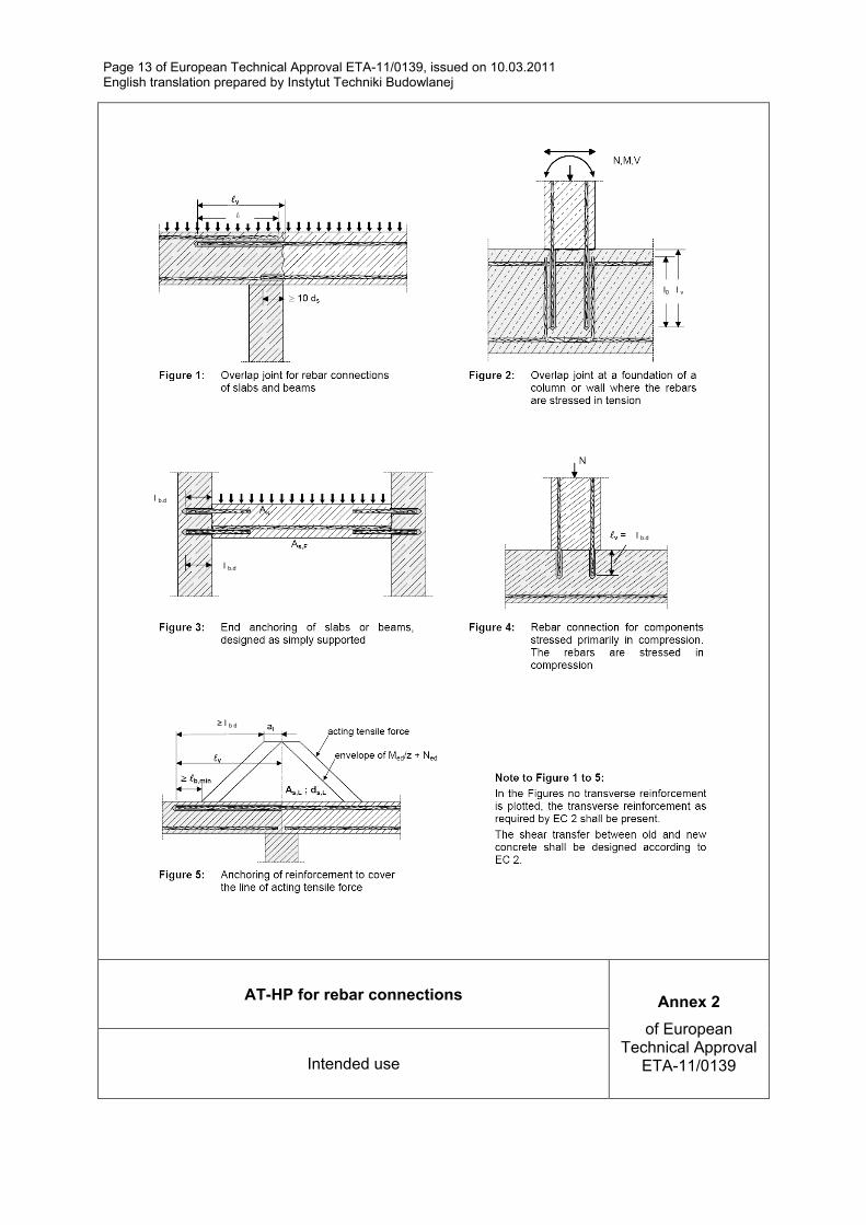
The rebar connections may only be carried out in the manner, which is also possible with reinforcing bars, e.g. those in the following applications:
– an overlapping joint with existing reinforcement in a building component (Figures 1 and 2, Annex 2),
– anchoring of the reinforcement at a slab or beam support (Figure 3, Annex 2; end support of a slab, designed as simply supported, as well as appropriate reinforcement for restraint forces),
– anchoring of reinforcement of building components stressed primarily in compression (Figure 4, Annex 2),
– anchoring of reinforcement to cover the line of acting tensile force (Figure 5, Annex 2).
The post-installed rebar connections may be installed in dry or wet concrete and it must not be installed in flooded holes.
The post-installed rebar connections may be used in the temperature range -40°C to +40°C (max. short term temperature +40°C and max. long term temperature +24°C).

Page 4 of European Technical Approval ETA-11/0139, issued on 10.03.2011 English translation prepared by Instytut Techniki Budowlanej
This ETA covers anchoring in bore holes made with hammer drilling.
The provisions made in this European Technical Approval are based on an assumed intended working life of the product of 50 years. The indications given on the working life cannot be interpreted as a guarantee given by the producer or Approval Body, but are to be regarded only as a means for choosing the right products in relation to the expected economically reasonable working life of the works.
2 Characteristics of product and methods of verification
2.1 Characteristics of product
The post-installed rebar connections correspond to the drawings and provisions given in Annexes 1 to 10. The characteristic material values, dimensions and tolerances not indicated in Annexes shall correspond to the respective values laid down in the technical documentation6 of this European Technical Approval.
Each mortar cartridge is marked with the identifying mark of the producer and with the trade name. The rebars are either delivered with the mortar cartridges or commercial standard rebars purchased separately.
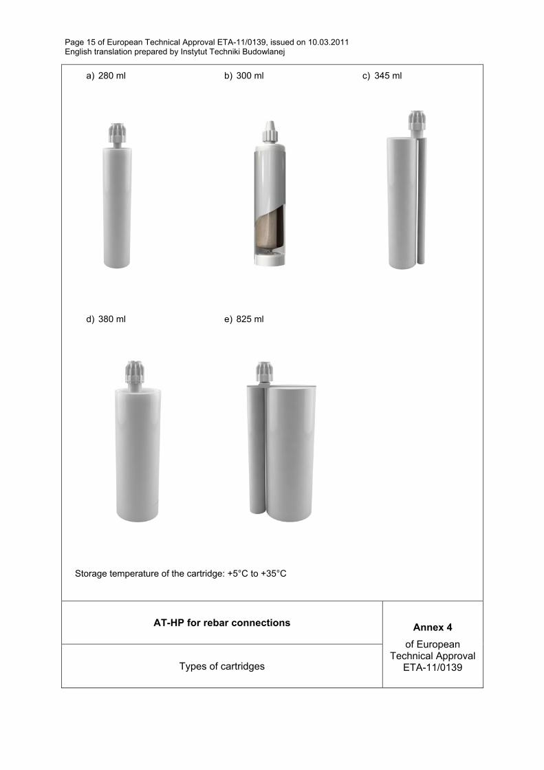
The two components of the AT-HP injection mortar are delivered in unmixed condition in cartridges of different sizes and types: 280 ml and 380 ml (coaxial), 345 ml and 825 ml (side by side), 300 ml (two part foil capsule in the cartridge) in accordance with Annex 1 and 4.
2.2 Methods of verification
The assessment of fitness of the post-installed rebar connections for the intended use in relation to the requirements for mechanical resistance and stability and safety in use in the sense of the Essential Requirements 1 and 4 has been made in accordance with the ETAG 001 Guideline for European Technical Approval of “Metal anchors for use in concrete”, Part 1: “Anchors in general” and Part 5: “Bonded anchors” and EOTA Technical Report TR 023 “Assessment of post-installed rebar connections”.
In addition to the specific clauses relating to dangerous substances contained in this European Technical Approval, there may be other requirements applicable to the products falling within its scope (e.g. transposed European legislation and national laws, regulations and administrative provisions). In order to meet the provisions of the Construction Products Directive, these requirements need also to be complied with, when and where they apply.
3 Evaluation of Conformity and CE marking
3.1 System of attestation of conformity
The system of attestation of conformity 2 (i) (referred to as system 1) according to Council Directive 89/106/EEC Annex III laid down by the European Commission provides:
6 The technical documentation of this European Technical Approval is deposited at Instytut Techniki Budowlanej
and, as far as relevant for the tasks of the approved body involved in the attestation of conformity procedure, may be handed over only to the approved body involved.
Page 5 of European Technical Approval ETA-11/0139, issued on 10.03.2011 English translation prepared by Instytut Techniki Budowlanej
(a) Tasks of the manufacturer:
1) factory production control,
2) further testing of samples taken at the factory by the manufacturer in accordance with a prescribed test plan;
(b) Tasks of the approved body:
1) initial type-testing of the product,
2) initial inspection of factory and of factory production control,
3) continuous surveillance, assessment and approval of factory production control.
3.2 Responsibilities
3.2.1 Tasks of the manufacturer; factory production control
The manufacturer has a factory production control system in the plant and shall exercises permanent internal control of production. All the elements, requirements and provisions adopted by the manufacturer are documented in a systematic manner in the form of written policies and procedures. This production control system ensures that the product is in conformity with the European Technical Approval.
The manufacturer shall only use raw materials supplied with the relevant inspection documents as laid down in the control plan7. The incoming raw materials shall be subject to controls and tests by the manufacturer before acceptance. Check of incoming materials such as nuts, washers, threaded rods, resin, hardeners shall include control of the inspection documents presented by suppliers (comparison with nominal values) by verifying dimensions and determining material properties.
The frequency of controls and tests conducted during production is laid down in the control plan7 taking account of the automated manufacturing process.
The results of factory production control are recorded and evaluated. The records include at least the following information:
– designation of the product, basic material and components,
– type of control or testing,
– date of manufacture of the product and date of testing of the product or basic material or components,
– result of control and testing and, if appropriate, comparison with requirements,
– signature of person responsible for factory production control.
The records shall be presented to the approved body involved in continuous surveillance. On request, they shall be presented to Instytut Techniki Budowlanej.
Details of the extent, nature and frequency of testing and controls to be performed within the factory production control shall correspond to the control plan7 which is part of the technical documentation of this European Technical Approval.
7 The control plan has been deposited at Instytut Techniki Budowlanej and may be handed over only to the
approved body involved in the attestation of conformity procedure.
Page 6 of European Technical Approval ETA-11/0139, issued on 10.03.2011 English translation prepared by Instytut Techniki Budowlanej
3.2.2 Tasks of the approved body
3.2.2.1 Initial type-testing of the product
For initial type-testing the results of the tests performed as part of the assessment for the European Technical Approval shall be used unless there are changes in the production line or plant. In such cases the necessary initial type-testing has to be agreed between the Instytut Techniki Budowlanej and the approved body involved.
3.2.2.2 Initial inspection of factory and of factory production control
The approved body shall ascertain that, in accordance with the control plan7, the factory, in particular the staff and equipment, and the factory production control are suitable to ensure continuous and orderly manufacturing of the anchor according to the specifications mentioned in clause 2.1 as well as to the Annexes to this European Technical Approval.
3.2.2.3 Continuous surveillance
Continuous surveillance and assessment of factory production control have to be performed according to the control plan7.
The approved body shall visit the factory at least once a year for surveillance. It has to be verified that the system of factory production control and the specified automated manufacturing process are maintained taking account of the control plan7.
The results of continuous surveillance shall be made available on demand by the approved body to Instytut Techniki Budowlanej. In cases where the provisions of the European Technical Approval and the control plan7 are no longer fulfilled the conformity certificate shall be withdrawn.
3.3 CE–marking
The CE marking shall be affixed on each packaging of the injection mortar. The letters “CE” shall be accompanied by the following information:
– name and address of the holder of the approval,
– identification number of the approved body,
– last two digits of the year in which the CE marking was affixed,
– number of the EC certificate of conformity,
– number of the European Technical Approval,
– number of the guideline for the European Technical Approval.
4 Assumptions under which the fitness of the product for the intended use was favourably assessed
4.1 Manufacturing
The products are manufactured in accordance with the provisions of the European Technical Approval using the automated manufacturing process as identified during inspection of the manufacturing plant by Instytut Techniki Budowlanej and laid down in the technical documentation.
7 see page 5
Page 7 of European Technical Approval ETA-11/0139, issued on 10.03.2011 English translation prepared by Instytut Techniki Budowlanej
4.2 Drafting
Rebar connections must be designed in keeping with good engineering practice. Considering the loads to be anchored, design calculations and design drawings must be produced in a way they can be checked. At least the following items must be given in the design drawings:
– grade of concrete strength,
– diameter, drilling technique, concrete cover, spacing and embedment depth of the rebar,
– kind of preparation of the joint between building component being connected including the thickness of concrete layer that has to be removed.
4.3 Rebar connections design
4.3.1 General
The actual position of the reinforcement in the existing structure shall be determined on the basis of the construction documentation and taken into account when designing.
The design of the post-installed rebar connections according to Annex 2 and determination of the internal section forces to be transferred in the construction joint shall be verified in accordance with EN 1992-1-1.
The minimum clear spacing between two post-installed rebars shall be: a = 40 mm ≥ 4 · Ø (according to Annex 8).
4.3.2 Determination of the basic anchorage length
The required basic anchorage length lb,rqd shall be determined in accordance with EN 1992-1-1, clause 8.4.3:
lb,rqd = (Ø / 4) · (σsd / fbd)
where:
Ø = diameter of the rebar
σsd = calculated design stress of the rebar
fbd = design value of bond strength according to Annex 8, Table 7
in consideration of the coefficient related to the quality of bond conditions and of the coefficient related to the rebar diameter.
4.3.3 Determination of the design anchorage length
The required design anchorage length lbd shall be determined in accordance with EN 1992-1-1, clause 8.4.4:
lbd = α1 · α2 · α3 · α4 · α5 · lb,rqd ≥ lb,min
where: α1, α2, α3, α4, α5 determined acc. to EN 1992-1-1, Table 8.2:
α1 = 1,0 for straight rebars
α2 = 0,7 ≤ α2 ≤ 1,0 calculated acc. to EN 1992-1-1, Table 8.2
Page 8 of European Technical Approval ETA-11/0139, issued on 10.03.2011 English translation prepared by Instytut Techniki Budowlanej
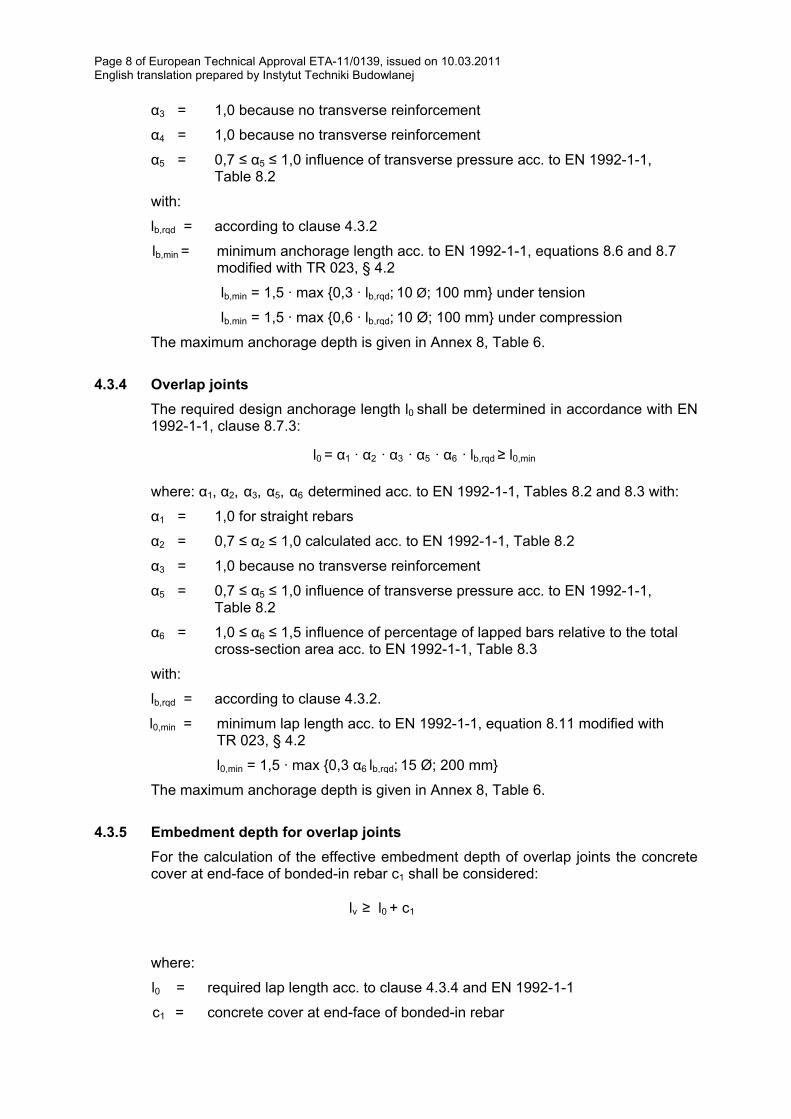
α3 = 1,0 because no transverse reinforcement
α4 = 1,0 because no transverse reinforcement
α5 = 0,7 ≤ α5 ≤ 1,0 influence of transverse pressure acc. to EN 1992-1-1, Table 8.2
with:
lb,rqd = according to clause 4.3.2
lb,min = minimum anchorage length acc. to EN 1992-1-1, equations 8.6 and 8.7 modified with TR 023, § 4.2
lb,min = 1,5 · max {0,3 · lb,rqd; 10 Ø; 100 mm} under tension
lb,min = 1,5 · max {0,6 · lb,rqd; 10 Ø; 100 mm} under compression
The maximum anchorage depth is given in Annex 8, Table 6.
4.3.4 Overlap joints
The required design anchorage length l0 shall be determined in accordance with EN 1992-1-1, clause 8.7.3:
l0 = α1 · α2 · α3 · α5 · α6 · lb,rqd ≥ l0,min
where: α1, α2, α3, α5, α6 determined acc. to EN 1992-1-1, Tables 8.2 and 8.3 with:
α1 = 1,0 for straight rebars
α2 = 0,7 ≤ α2 ≤ 1,0 calculated acc. to EN 1992-1-1, Table 8.2
α3 = 1,0 because no transverse reinforcement
α5 = 0,7 ≤ α5 ≤ 1,0 influence of transverse pressure acc. to EN 1992-1-1, Table 8.2
α6 = 1,0 ≤ α6 ≤ 1,5 influence of percentage of lapped bars relative to the total cross-section area acc. to EN 1992-1-1, Table 8.3
with:
lb,rqd = according to clause 4.3.2.
l0,min = minimum lap length acc. to EN 1992-1-1, equation 8.11 modified with TR 023, § 4.2
l0,min = 1,5 · max {0,3 α6 lb,rqd; 15 Ø; 200 mm}
The maximum anchorage depth is given in Annex 8, Table 6.
4.3.5 Embedment depth for overlap joints
For the calculation of the effective embedment depth of overlap joints the concrete cover at end-face of bonded-in rebar c1 shall be considered:
lv ≥ l0 + c1
where:
l0 = required lap length acc. to clause 4.3.4 and EN 1992-1-1
c1 = concrete cover at end-face of bonded-in rebar

Page 9 of European Technical Approval ETA-11/0139, issued on 10.03.2011 English translation prepared by Instytut Techniki Budowlanej
If the clear distance between overlapping rebars is greater than 4 Ø the overlap length shall be enlarged by the difference between the clear distance and 4 Ø.
4.3.6 Concrete cover
The concrete cover required for bonded-in rebars is shown in Annex 8.
Furthermore the minimum concrete cover given in EN 1992-1-1, clause 4.4.1.2 shall be observed.
4.3.7 Transverse reinforcement
The requirements of transverse reinforcement in the area of the post-installed rebar connection shall comply with EN 1992-1-1, clause 8.7.4.
4.3.8 Connection joint
The transfer of shear forces between new concrete and existing structure shall be designed according to EN 1992-1-1. The joints for concreting shall be roughened to at least such an extent that aggregate protrude.
In the case of carbonated surface of the existing concrete structure the carbonated layer shall be removed in the area of the post-installed rebar connection with a diameter of Ø + 60 mm prior to the installation of the new rebar.
The depth of concrete to be removed shall correspond to at least the minimum concrete cover for the respective environmental conditions in accordance with EN 1992-1-1.
The foregoing may be neglected if building components are new and not carbonated and if building components are in dry conditions.
4.4 Installation
The fitness for use of the post-installed rebars can only be assumed if the rebar is installed as follows:
– installation of the post-installed rebars shall be done only by suitable trained installer and under supervision on the site; the condition under which an installer may be considered as suitable trained and the condition for supervision on site are up to the Member States in which the installation is done,
– use of the injection system only as supplied by the manufacturer without changing the components,
– installation in accordance with the manufacturer’s specifications and drawings using the tools indicated in the technical documentation of this European Technical Approval,
– check before rebar installation to ensure that the strength class of the concrete in which the post-installed rebar connection is to be placed is in the range given and is not lower than that of the concrete to which the characteristics loads apply,
– check of concrete being well compacted, e.g. without significant voids,
– check the position of the existing rebars,
– keeping the anchorage depth as specified in the design drawings,
– keeping the concrete cover and spacing as specified in the design drawings,
– positioning of the drill holes without damaging the reinforcement,
Page 10 of European Technical Approval ETA-11/0139, issued on 10.03.2011 English translation prepared by Instytut Techniki Budowlanej
– in case of aborted drill hole: the drill hole shall be filled with mortar,
– rebar installation ensuring the specified embedment depth, that is the appropriate depth marking of the rebar not exceeding the concrete surface,
– clearing the hole of drilling dust: the hole shall be cleaned by at least two blowing operations, by at least two brushing operations followed again by at least two blowing operations, before brushing cleaning the brush and checking whether the brush diameter according to Annex 5 is sufficient,
– mortar injection by using the equipment including the special mixing nozzle (mixer) shown in Annex 4; discarding the first swings of mortar of each new cartridge until an homogeneous color is achieved; taking from the manufacturer instruction the admissible processing time (open time) of a cartridge as a function of the ambient temperature of the concrete; filling the drill hole uniformly from the drill hole bottom, in order to avoid entrapment of air; removing the special mixing nozzle slowly bit by bit during pressing-out; filling the drill hole with a quantity of the injection mortar corresponding to 2/3 of the drill hole depth; inserting immediately the rebar, slowly and with a slight twisting motion, removing excess of injection mortar around the rod; observing the loading (curing) time according to Annex 3, Table 5 until the rebar may be loaded;
– mortar installation temperature shall be at least +5°C,
– during installation and curing of the injection mortar the temperature of the building component must not be less than -5°C and no more than +35°C, observing the curing time given in Annex 3.
4.4.1 Responsibility of the manufacturer
It is the manufacturer's responsibility to ensure that the information on the specific conditions according to clause 1 and 2 including Annexes referred to clause 4 is given to those who are concerned. This information may be made by reproduction of the respective parts of the European Technical Approval. In addition all installation data shall be shown clearly on the package and/or on an enclosed instruction sheet, preferably using illustration(s).
The minimum data required are:
– drill bit diameter,
– diameter of rebar,
– admissible service temperature range,
– curing time of the injection mortar depending on the installation temperature,
– information on the installation procedure, including cleaning of the drill hole, preferably by means of an illustration,
– reference to any special installation equipment needed,
– identification of the manufacturing batch.
All the data shall be presented in a clear and explicit form.
Page 11 of European Technical Approval ETA-11/0139, issued on 10.03.2011 English translation prepared by Instytut Techniki Budowlanej
5 Recommendations on packaging, transport and storage
The mortar cartridges shall be protected against sun radiation and shall be stored according to the manufacturer's instructions in dry conditions at temperatures of at least +5°C to not more than +35°C.
Mortar cartridges with expired shelf life must no longer be used.
On behalf of Instytut Techniki Budowlanej
Marek Kaproń Director of ITB
Page 12 of European Technical Approval ETA-11/0139, issued on 10.03.2011 English translation prepared by Instytut Techniki Budowlanej
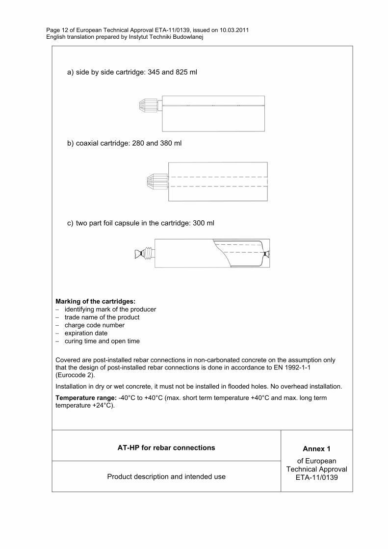
a) side by side cartridge: 345 and 825 ml
b) coaxial cartridge: 280 and 380 ml
c) two part foil capsule in the cartridge: 300 ml
Marking of the cartridges: identifying mark of the producer trade name of the product charge code number expiration date curing time and open time
Covered are post-installed rebar connections in non-carbonated concrete on the assumption only that the design of post-installed rebar connections is done in accordance to EN 1992-1-1 (Eurocode 2).
Installation in dry or wet concrete, it must not be installed in flooded holes. No overhead installation.
Temperature range: -40°C to +40°C (max. short term temperature +40°C and max. long term temperature +24°C).
AT-HP for rebar connections Annex 1
of European Technical Approval
ETA-11/0139 Product description and intended use
Page 13 of European Technical Approval ETA-11/0139, issued on 10.03.2011 English translation prepared by Instytut Techniki Budowlanej
AT-HP for rebar connections Annex 2
of European Technical Approval
ETA-11/0139 Intended use
≥ l b,d
l b,d
l b,d
l b,d
l b,d
l0
l0 l v
Page 14 of European Technical Approval ETA-11/0139, issued on 10.03.2011 English translation prepared by Instytut Techniki Budowlanej
AT-HP for rebar connections Annex 3
of European Technical Approval
ETA-11/0139 Materials and curing time
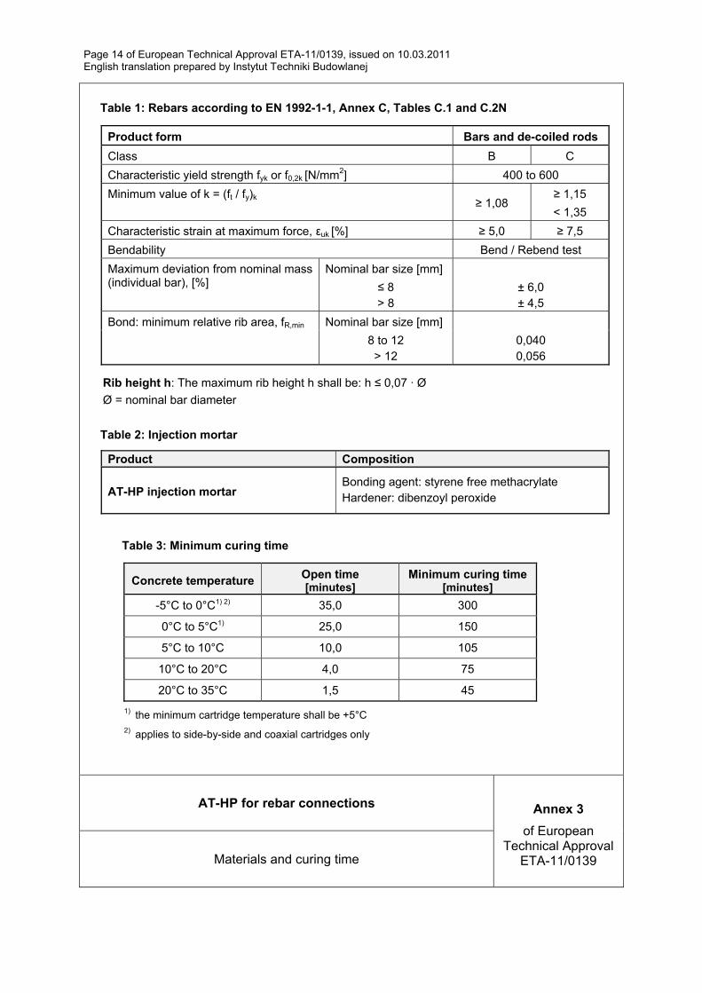
Table 1: Rebars according to EN 1992-1-1, Annex C, Tables C.1 and C.2N
Product form Bars and de-coiled rods
Class B C
Characteristic yield strength fyk or f0,2k [N/mm2] 400 to 600
Minimum value of k = (ft / fy)k ≥ 1,08
≥ 1,15
< 1,35
Characteristic strain at maximum force, εuk [%] ≥ 5,0 ≥ 7,5
Bendability Bend / Rebend test
Maximum deviation from nominal mass (individual bar), [%]
Nominal bar size [mm]
≤ 8 > 8
± 6,0 ± 4,5
Bond: minimum relative rib area, fR,min Nominal bar size [mm]
8 to 12 > 12
0,040 0,056
Rib height h: The maximum rib height h shall be: h ≤ 0,07 · Ø
Ø = nominal bar diameter
Table 2: Injection mortar
Product Composition
AT-HP injection mortar Bonding agent: styrene free methacrylate Hardener: dibenzoyl peroxide
Table 3: Minimum curing time
Concrete temperature Open time [minutes]
Minimum curing time [minutes]
-5°C to 0°C1) 2) 35,0 300
0°C to 5°C1) 25,0 150
5°C to 10°C 10,0 105
10°C to 20°C 4,0 75
20°C to 35°C 1,5 45
1) the minimum cartridge temperature shall be +5°C 2) applies to side-by-side and coaxial cartridges only
Page 15 of European Technical Approval ETA-11/0139, issued on 10.03.2011 English translation prepared by Instytut Techniki Budowlanej
a) 280 ml
b) 300 ml c) 345 ml
d) 380 ml
e) 825 ml
Storage temperature of the cartridge: +5°C to +35°C
AT-HP for rebar connections Annex 4
of European Technical Approval
ETA-11/0139 Types of cartridges
Page 16 of European Technical Approval ETA-11/0139, issued on 10.03.2011 English translation prepared by Instytut Techniki Budowlanej
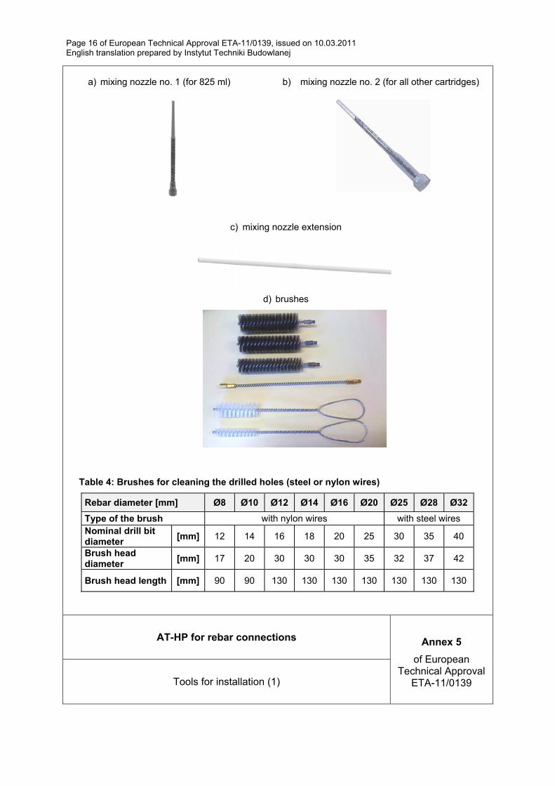
a) mixing nozzle no. 1 (for 825 ml)
b) mixing nozzle no. 2 (for all other cartridges)
c) mixing nozzle extension
d) brushes
Table 4: Brushes for cleaning the drilled holes (steel or nylon wires)
Rebar diameter [mm] Ø8 Ø10 Ø12 Ø14 Ø16 Ø20 Ø25 Ø28 Ø32
Type of the brush with nylon wires with steel wires Nominal drill bit diameter
[mm] 12 14 16 18 20 25 30 35 40
Brush head diameter
[mm] 17 20 30 30 30 35 32 37 42
Brush head length [mm] 90 90 130 130 130 130 130 130 130
AT-HP for rebar connections Annex 5
of European Technical Approval
ETA-11/0139 Tools for installation (1)
Page 17 of European Technical Approval ETA-11/0139, issued on 10.03.2011 English translation prepared by Instytut Techniki Budowlanej
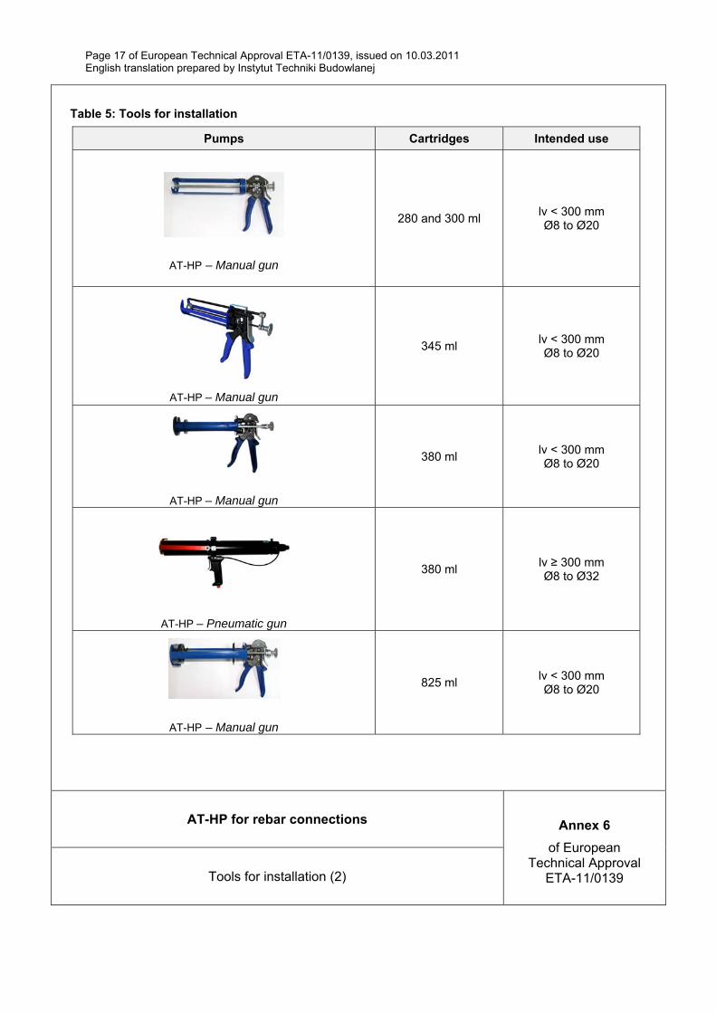
Table 5: Tools for installation
Pumps Cartridges Intended use
AT-HP – Manual gun
280 and 300 ml lv < 300 mm Ø8 to Ø20
AT-HP – Manual gun
345 ml lv < 300 mm Ø8 to Ø20
AT-HP – Manual gun
380 ml lv < 300 mm Ø8 to Ø20
AT-HP – Pneumatic gun
380 ml lv ≥ 300 mm Ø8 to Ø32
AT-HP – Manual gun
825 ml lv < 300 mm Ø8 to Ø20
AT-HP for rebar connections Annex 6
of European Technical Approval
ETA-11/0139 Tools for installation (2)

Page 18 of European Technical Approval ETA-11/0139, issued on 10.03.2011 English translation prepared by Instytut Techniki Budowlanej
AT-HP for rebar connections Annex 7
of European Technical Approval
ETA-11/0139 Installation procedure
1 Drill the hole with the correct diameter and depth (Annex 8, Table 6) using a rotary hammer drilling tool. Check the perpendicularity of the hole during the drilling operation.
2 Clean the hole from drilling dust: the hole shall be cleaned by at least 2 blowing operations (with the compressed air – min. 6 bar)) and following by at least 2 brushing operations and following again by at least 2 blowing operations. Before brushing check if the brush diameter is sufficient (according to Annex 5, Table 4)
3 Insert the cartridge with mixing nozzle into the appropriate pump. Before starting to use the cartridge, eject a first part of the product, being sure that the two components are completely mixed. The complete mixing is reached only after that the product, obtained by mixing the two component, comes out from the mixer with an uniform color.
4 Fill the drilled hole uniformly starting from the drilled hole bottom, filling the drill hole with a quantity of the injection mortar corresponding to 2/3 of the drill hole depth. Insert immediately the rebar (rebar should be marked with the embedment depth mark) slowly, with a slight twisting motion and remove excess of injection mortar around the rebar.
5
The curing time according to Annex 3, Table 3 shall be taken into account.
6
Start with the loading phase.
Page 19 of European Technical Approval ETA-11/0139, issued on 10.03.2011 English translation prepared by Instytut Techniki Budowlanej
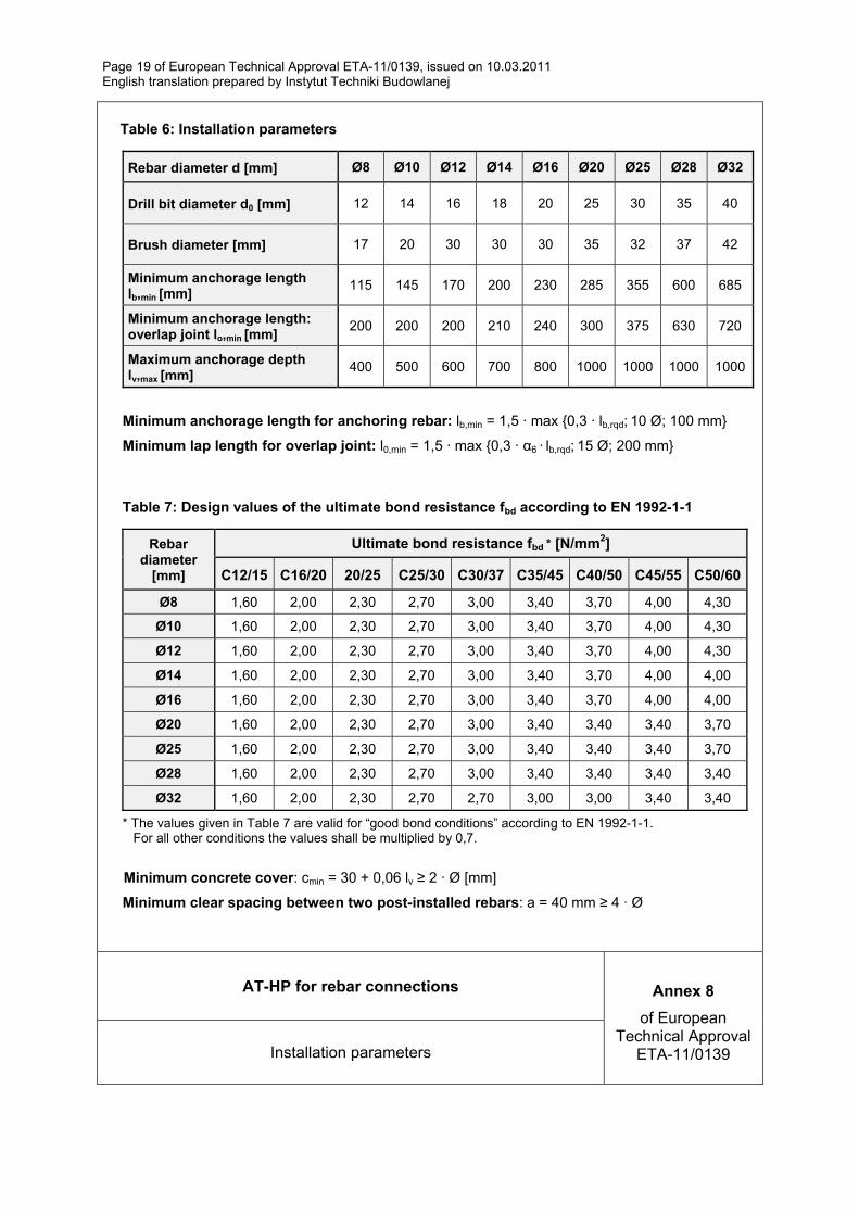
Table 6: Installation parameters
Rebar diameter d [mm] Ø8 Ø10 Ø12 Ø14 Ø16 Ø20 Ø25 Ø28 Ø32
Drill bit diameter d0 [mm] 12 14 16 18 20 25 30 35 40
Brush diameter [mm] 17 20 30 30 30 35 32 37 42
Minimum anchorage length lb,min [mm]
115 145 170 200 230 285 355 600 685
Minimum anchorage length: overlap joint lo,min [mm]
200 200 200 210 240 300 375 630 720
Maximum anchorage depth lv,max [mm]
400 500 600 700 800 1000 1000 1000 1000
Minimum anchorage length for anchoring rebar: lb,min = 1,5 · max {0,3 · lb,rqd; 10 Ø; 100 mm}
Minimum lap length for overlap joint: l0,min = 1,5 · max {0,3 · α6 · lb,rqd; 15 Ø; 200 mm}
Table 7: Design values of the ultimate bond resistance fbd according to EN 1992-1-1
Rebar diameter
[mm]
Ultimate bond resistance fbd * [N/mm2]
C12/15 C16/20 20/25 C25/30 C30/37 C35/45 C40/50 C45/55 C50/60
Ø8 1,60 2,00 2,30 2,70 3,00 3,40 3,70 4,00 4,30
Ø10 1,60 2,00 2,30 2,70 3,00 3,40 3,70 4,00 4,30
Ø12 1,60 2,00 2,30 2,70 3,00 3,40 3,70 4,00 4,30
Ø14 1,60 2,00 2,30 2,70 3,00 3,40 3,70 4,00 4,00
Ø16 1,60 2,00 2,30 2,70 3,00 3,40 3,70 4,00 4,00
Ø20 1,60 2,00 2,30 2,70 3,00 3,40 3,40 3,40 3,70
Ø25 1,60 2,00 2,30 2,70 3,00 3,40 3,40 3,40 3,70
Ø28 1,60 2,00 2,30 2,70 3,00 3,40 3,40 3,40 3,40
Ø32 1,60 2,00 2,30 2,70 2,70 3,00 3,00 3,40 3,40
* The values given in Table 7 are valid for “good bond conditions” according to EN 1992-1-1. For all other conditions the values shall be multiplied by 0,7.
Minimum concrete cover: cmin = 30 + 0,06 lv ≥ 2 · Ø [mm]
Minimum clear spacing between two post-installed rebars: a = 40 mm ≥ 4 · Ø
AT-HP for rebar connections Annex 8
of European Technical Approval
ETA-11/0139 Installation parameters
Page 20 of European Technical Approval ETA-11/0139, issued on 10.03.2011 English translation prepared by Instytut Techniki Budowlanej
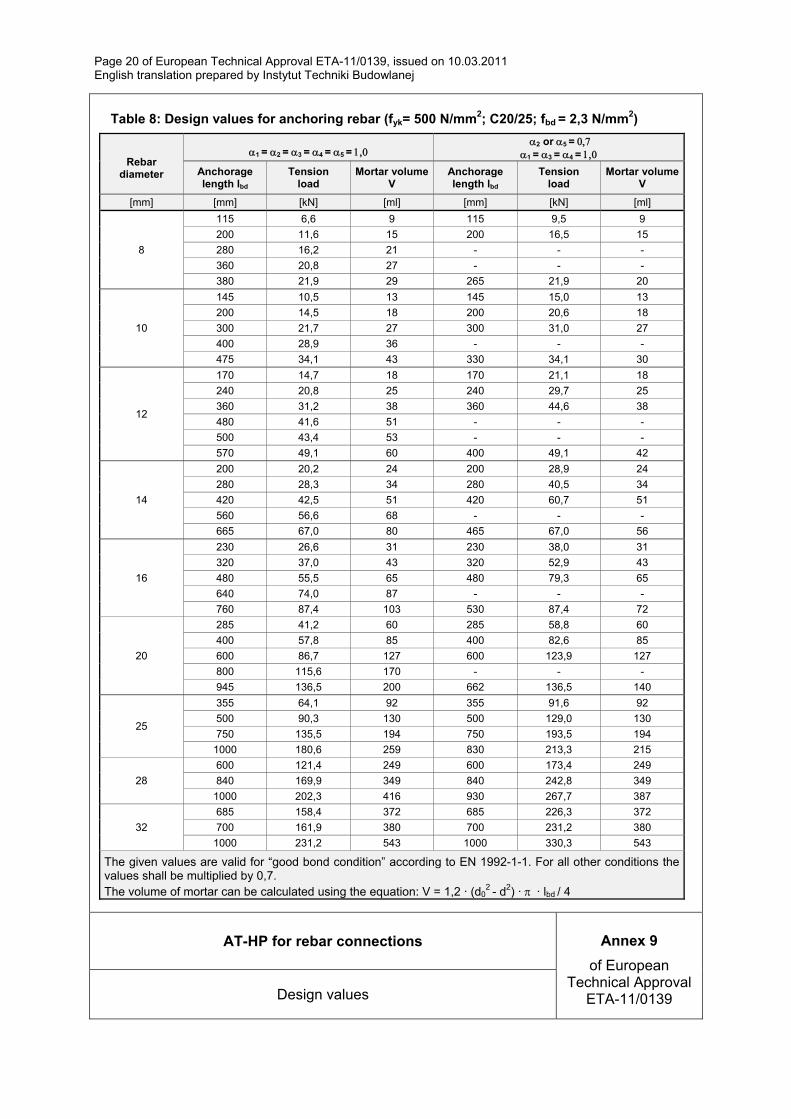
Table 8: Design values for anchoring rebar (fyk= 500 N/mm2; C20/25; fbd = 2,3 N/mm2)
Rebar diameter
1 =2 =3 =4 =5 = 2 or5 =
1 =3 =4 =
Anchorage length lbd
Tension load
Mortar volume V
Anchorage length lbd
Tension load
Mortar volume V
[mm] [mm] [kN] [ml] [mm] [kN] [ml]
8
115 6,6 9 115 9,5 9
200 11,6 15 200 16,5 15
280 16,2 21 - - -
360 20,8 27 - - -
380 21,9 29 265 21,9 20
10
145 10,5 13 145 15,0 13
200 14,5 18 200 20,6 18
300 21,7 27 300 31,0 27
400 28,9 36 - - -
475 34,1 43 330 34,1 30
12
170 14,7 18 170 21,1 18
240 20,8 25 240 29,7 25
360 31,2 38 360 44,6 38
480 41,6 51 - - -
500 43,4 53 - - -
570 49,1 60 400 49,1 42
14
200 20,2 24 200 28,9 24
280 28,3 34 280 40,5 34
420 42,5 51 420 60,7 51
560 56,6 68 - - -
665 67,0 80 465 67,0 56
16
230 26,6 31 230 38,0 31
320 37,0 43 320 52,9 43
480 55,5 65 480 79,3 65
640 74,0 87 - - -
760 87,4 103 530 87,4 72
20
285 41,2 60 285 58,8 60
400 57,8 85 400 82,6 85
600 86,7 127 600 123,9 127
800 115,6 170 - - -
945 136,5 200 662 136,5 140
25
355 64,1 92 355 91,6 92
500 90,3 130 500 129,0 130
750 135,5 194 750 193,5 194
1000 180,6 259 830 213,3 215
28
600 121,4 249 600 173,4 249
840 169,9 349 840 242,8 349
1000 202,3 416 930 267,7 387
32
685 158,4 372 685 226,3 372
700 161,9 380 700 231,2 380
1000 231,2 543 1000 330,3 543
The given values are valid for “good bond condition” according to EN 1992-1-1. For all other conditions the values shall be multiplied by 0,7. The volume of mortar can be calculated using the equation: V = 1,2 · (d0
2 - d2) ·· lbd / 4
AT-HP for rebar connections Annex 9
of European Technical Approval
ETA-11/0139 Design values
Page 21 of European Technical Approval ETA-11/0139, issued on 10.03.2011 English translation prepared by Instytut Techniki Budowlanej
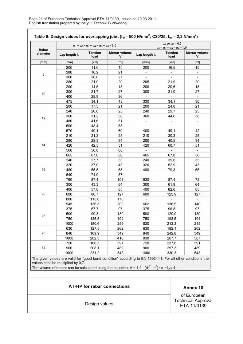
Table 9: Design values for overlapping joint (fyk= 500 N/mm2; C20/25; fbd = 2,3 N/mm2)
Rebar diameter
1 =2 =3 =4 =5 =6 = 2 or5 =
1 =3 =4 =6 =
Lap length l0 Tension
load Mortar volume
V Lap length l0
Tension load
Mortar volume V
[mm] [mm] [kN] [ml] [mm] [kN] [ml]
8
200 11,6 15 200 16,5 15 280 16,2 21 - - - 360 20,8 27 - - - 380 21,9 29 265 21,9 20
10
200 14,5 18 200 20,6 18 300 21,7 27 300 31,0 27 400 28,9 36 - - - 475 34,1 43 330 34,1 30
12
200 17,3 21 200 24,8 21 240 20,8 25 240 29,7 25 360 31,2 38 360 44,6 38 480 41,6 51 - - - 500 43,4 53 - - - 570 49,1 60 400 49,1 42
14
210 21,2 25 210 30,3 25 280 28,3 34 280 40,5 34 420 42,5 51 420 60,7 51 560 56,6 68 - - - 665 67,0 80 465 67,0 56
16
240 27,7 33 240 39,6 33 320 37,0 43 320 52,9 43 480 55,5 65 480 79,3 65 640 74,0 87 - - - 760 87,4 103 530 87,4 72
20
300 43,3 64 300 61,9 64 400 57,8 85 400 82,6 85 600 86,7 127 600 123,9 127 800 115,6 170 - - - 945 136,5 200 662 136,5 140
25
375 67,7 97 375 96,8 97 500 90,3 130 500 129,0 130 750 135,5 194 750 193,5 194
1000 180,6 259 830 213,3 215
28 630 127,5 262 630 182,1 262 840 169,9 349 840 242,8 349
1000 202,3 416 930 267,7 387
32 720 166,5 391 720 237,8 391 900 208,1 489 900 297,3 489
1000 231,2 543 1000 330,3 543
The given values are valid for “good bond condition” according to EN 1992-1-1. For all other conditions the values shall be multiplied by 0,7. The volume of mortar can be calculated using the equation: V = 1,2 · (d0
2 - d2) ·· lbd / 4
AT-HP for rebar connections Annex 10
of European Technical Approval
ETA-11/0139 Design values

ISBN 978-83-249-4652-5